EP0453196A2 - Transformer differential relay - Google Patents
Transformer differential relay Download PDFInfo
- Publication number
- EP0453196A2 EP0453196A2 EP91303273A EP91303273A EP0453196A2 EP 0453196 A2 EP0453196 A2 EP 0453196A2 EP 91303273 A EP91303273 A EP 91303273A EP 91303273 A EP91303273 A EP 91303273A EP 0453196 A2 EP0453196 A2 EP 0453196A2
- Authority
- EP
- European Patent Office
- Prior art keywords
- signal
- generating
- operate
- output
- magnitude
- Prior art date
- Legal status (The legal status is an assumption and is not a legal conclusion. Google has not performed a legal analysis and makes no representation as to the accuracy of the status listed.)
- Granted
Links
Images


Classifications
-
- G—PHYSICS
- G06—COMPUTING; CALCULATING OR COUNTING
- G06F—ELECTRIC DIGITAL DATA PROCESSING
- G06F11/00—Error detection; Error correction; Monitoring
- G06F11/07—Responding to the occurrence of a fault, e.g. fault tolerance
- G06F11/14—Error detection or correction of the data by redundancy in operation
- G06F11/1402—Saving, restoring, recovering or retrying
- G06F11/1415—Saving, restoring, recovering or retrying at system level
- G06F11/1435—Saving, restoring, recovering or retrying at system level using file system or storage system metadata
-
- H—ELECTRICITY
- H02—GENERATION; CONVERSION OR DISTRIBUTION OF ELECTRIC POWER
- H02H—EMERGENCY PROTECTIVE CIRCUIT ARRANGEMENTS
- H02H7/00—Emergency protective circuit arrangements specially adapted for specific types of electric machines or apparatus or for sectionalised protection of cable or line systems, and effecting automatic switching in the event of an undesired change from normal working conditions
- H02H7/04—Emergency protective circuit arrangements specially adapted for specific types of electric machines or apparatus or for sectionalised protection of cable or line systems, and effecting automatic switching in the event of an undesired change from normal working conditions for transformers
- H02H7/045—Differential protection of transformers
- H02H7/0455—Differential protection of transformers taking into account saturation of current transformers
Landscapes
- Engineering & Computer Science (AREA)
- Power Engineering (AREA)
- Theoretical Computer Science (AREA)
- Library & Information Science (AREA)
- Quality & Reliability (AREA)
- Physics & Mathematics (AREA)
- General Engineering & Computer Science (AREA)
- General Physics & Mathematics (AREA)
- Protection Of Transformers (AREA)
- Emergency Protection Circuit Devices (AREA)
Abstract
Description
- This invention relates to protective relay circuits for use in AC power distribution systems and more particularly to transformer differential relays.
- As part of the protection scheme for AC power distribution systems, it is desirable to detect faults occurring within the transformers used in the system. Upon detection of a fault within the transformer, circuit breakers are operated to disconnect the input and/or the output of the transformer thereby protecting the transformer as well as those portions of the power distribution system connected to the transformer.
- Transformer differential relays have been used in the past to detect faults within a transformer. Such relays operate upon the theory that, in an unfaulted transformer, the current Ip in the input windings is equal to the current Is in the output windings multiplied by the output to input winding turns ratio Rt; that is, Ip = Rt Is. Upon occurrence of an internal fault, the quantities Ip and Rt Is are no longer equal. Accordingly, a transformer differential relay continuously compares the magnitude of the quantities Ip and Rt Is and will generate a trip signal when the difference between the quantities Ip and Rt Is exceeds a predetermined maximum. The trip signal is used to operate one or more circuit breakers in order to disconnect the input and/or the output of the faulted transformer from the power distribution system.
- Although transformer differential relays work well to detect the occurrence of internal faults, they have been known to erroneously generate a trip signal as a result of transformer inrush current. Transformer inrush current occurs as a result of the application of voltage to the input windings. Voltage is applied to the transformer input windings when, for example, the system is initially powered or following the clearance of a fault in the system. The presence of inrush current causes a difference to occur in the quantities Ip and Rt Is. When the difference exceeds the predetermined maximum, occasionally the relay will generate a trip signal even thought the difference was caused by inrush current and not by an internal fault. As a result, the reliability of the relay and consequently the reliability of the entire AC power distribution system incorporating such a relay is diminished.
- Illustrative embodiments of the present invention seek to provide:
a method and apparatus for enhancing the reliability of transformer differential relays;
a method and apparatus which enable transformer differential relays to provide better discrimination between transformer current differentials due to transformer inrush current and current differentials due to the occurrence of a fault;
a method and apparatus which enable transformer differential relays to prevent the occurrence of a trip signal based solely on inrush current having a magnitude less than a predetermined value;
a method and apparatus for generating additional trip signal restraint in a transformer differential relay upon occurrence of an external fault;
a method and apparatus for increasing the reliability of the transformer differential relay in the presence of current transformer saturation on either internal or external faults; and/or
a method and apparatus for generating an additional trip signal operate quantity in a transformer differential relay when transformer differential current exceeds a predetermined maximum value. - An embodiment of the present invention comprises a transformer differential relay which includes means for inhibiting generation of a circuit breaker trip signal based solely upon transformer inrush current having a magnitude which is less than a predetermined maximum value. The trip signal inhibiting means comprises means for generating a vector sum of signals related to currents in the input and output windings of the transformer; means for measuring the magnitude of the positive portions of the vector sum and the negative portions of the vector sum; means for producing a restraint signal that is proportional to the absolute value of each of the input and output signals related to the currents in the input and output windings of the transformer; and means for providing a trip signal when the magnitude of the positive portions of the vector sum exceed a first predetermined maximum value plus the value of the restraint signal and the magnitude of the negative portions of the vector sum exceed a second predetermined maximum value, plus the value of the restraint signal.
- In the preferred embodiment, the vector sum of quantities relating to currents flowing in the windings of the transformer is generated as an operate signal. This vector sum operate signal is applied to the input of a positive half wave rectifier and the input of a negative half wave rectifier. The output of the positive half wave rectifier is applied to an operate input of a summing and integrating amplifier. The output of the negative half wave rectifier is applied to the input of an inverter, the output of which is applied to an operate input of a second summing and integrating amplifier. The output of the first and second summing and integrating amplifiers are applied to the inputs of a first and second level detector respectively. The first and second level detectors each generate an output signal when the magnitude of the net input signal applied thereto exceeds a predetermined value.
- The outputs of the first and second level detectors are applied to the inputs of a two input and gate. Upon coincidence of signals on the inputs of the and gate, an output trip signal is generated. Consequently, a trip signal is generated when the output of the first summing and integrating amplifier, which is related to the magnitude of the positive half wave rectified vector sum operate signal less the restraint signal, exceeds the predetermined threshold of the first level detector; and the output of the second summing and integrating amplifier, which is related to the magnitude of the negative half wave rectified vector sum operate signal less the restraint signal, exceeds the threshold of the second level detector.
- A better understanding of this invention can be more readily ascertained from the following description of a preferred embodiment when read in conjunction with the accompanying drawings in which:
- FIGURE 1 is a schematic diagram of a step down transformer having a star connected side and a delta connected side.
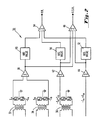
- FIGURE 2 is a schematic block diagram of a preferred embodiment of an input portion of a transformer differential relay in accordance with the present invention.
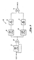
- FIGURE 3 is a schematic block diagram of a preferred embodiment of a harmonic restraint portion of the transformer differential relay in accordance with the present invention.
- FIGURE 4 is a schematic block diagram of a preferred embodiment of the remaining portion of the transformer differential relay in accordance with the present invention.
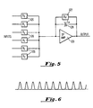
- FIGURE 5 is a schematic block diagram of a preferred embodiment of a summing and integrating amplifier.
- FIGURE 6 is a depiction of an exemplary waveform characteristic of transformer inrush current.
- The preferred embodiment of the transformer differential relay of the present invention is preferably used to protect transformers which are utilized in three phase alternating current electrical power distribution systems. The three phases are typically referred to as phase A, phase B and phase C. The type of transformers typically protected by transformer differential relays include three phase step up and step down power transformers. Such power transformers typically have a star connected winding and a delta connected winding but may have two star connected windings, a tapped star connected winding and a delta connected winding (autotransformer), two delta connected windings, or other combinations of star and delta connected windings. Figure 1 schematically depicts an exemplary step down transformer, generally designated 10, which transforms a higher voltage applied to its input windings, generally designated 12, to a lower voltage produced at its output windings, generally designated 14. It should be noted that the transformer depicted in Figure 1 is merely exemplary for purposes of this detailed description. Other types of transformers known by those skilled in the art to be usable in electrical power distribution systems are also protectable by the transformer differential relay of the present invention.
- As shown in Figure 1, the
input windings 12 are connected in a star configuration and theoutput windings 14 are connected in a delta configuration as is known to those skilled in the art. Theinput windings 12 are connected to phases A, B and C of, for example, a high voltage transmission line; and theoutput windings 14 are connected to phases A, B and C of, for example, a low voltage distribution line.Current transformer current transformer 22 is coupled to the phase A and phase B output windings; and produces and output signal which is representative of the vector sum of the current -IA flowing in the A phase output winding minus the current -IB flowing in the B phase output winding. Similarly,current transformer 24 produces an output signal which is representative of the vector sum of the current -IB minus the current -IC flowing in the C phase output winding; andcurrent transformer 26 produces and output signal which is representative of the vector sum of the current -IC minus the current -IA. The use of such current transformers to produce the signals indicated is well known to those of ordinary skill in the art. - As previously mentioned, transformer differential relays operate on the principal that, in an unfaulted transformer, the input current Ip is equal to the output current Is multiplied by the output to input turns ratio Rt. In a three phase system, the difference between the Ip and Rt Is quantities is usually measured for each phase current. For protected transformers having delta connected windings, the individual phase currents IA, IB and IC are beneficially resolvable into three vector sum currents -IA +IB, -IB +IC and -IC +IA since such are relatively easy to monitor using three current transformers coupled to the delta windings as depicted in Figure 1 and described above.
- Since it is necessary to monitor corresponding currents on both the input and output sides of the protected transformer in order that the difference between the Ip and Rt Is quantities have the proper significance in determining transformer faults, the individual phase currents monitored by the current transformers on the star connected side of the transformer will also be resolved into vector sum currents IA -IB, IB -IC and IC -IA as will be subsequently described. In this regard, it should be noted that the following detailed description is set forth with reference to one (IA -IB) of the three vector sum currents. Accordingly, the preferred embodiment described herein is one of three units, the other two units being associated with the IB -IC and IC -IA vector sum currents in this example.
- It has been found in that transformer inrush current is characterized by a substantially unipolar waveform which is essentially a portion of a sinusoid. See, for example, the waveform depicted in Figure 6. This is to be contrasted with a fault current which generally has a bipolar sinusoidal waveform. The transformer differential relay of the present invention operates on the principal that a circuit breaker trip output signal will be generated upon sensing a current having a bipolar waveform, the magnitude of which exceeds a first predetermined maximum value; and inhibiting the generation of a circuit breaker trip signal when the transformer current is substantially unipolar with a magnitude less than a second predetermined maximum value.
- Referring now to Figure 2, there is shown a schematic block diagram of the preferred embodiment of an input portion of a transformer differential relay in accordance with the present invention. The input portion, generally designated 30, comprises a first
current transformer 32; a secondcurrent transformer 34; and a thirdcurrent transformer 36. In the preferred embodiment described herein, these current transformers provide isolation and internal phase shift. The most economical method of providing the ratio balancing taps should be determined in accordance with the standard relay design practices as is known in the art. Each current transformer has an input winding and an output winding. A first resistor R₁, is connected between a first terminal of the output winding of each current transformer and reference; and a second resistor R₂ is connected between a second terminal of the output winding and reference such that the signal present at the second terminal has an inverted polarity with respect to the signal present at the first terminal. - The input winding of the first
current transformer 32 is connected to a current transformer (not shown) coupled to the phase A winding of the star connected side of the transformer protected by the transformer differential relay. Accordingly, the signal present at the first terminal of the output winding of the firstcurrent transformer 32 is related to the current IA flowing in the phase A winding of the star connected side of the protected transformer; and the signal present at the second terminal is a signal -IA having an inverted polarity with respect to the signal IA. The input winding of the secondcurrent transformer 34 is connected to a current transformer (not shown) coupled to the phase B winding of the star connected side of the transformer. Consequently, the signal present at the first terminal of the output winding of the secondcurrent transformer 34 is related to the current IB flowing in the phase B winding of the star connected side of the protected transformer; and the signal present at the second terminal is related to -IB. - The signal IA from the first
current transformer 32 is coupled to one input of a first summingamplifier 38. The signal -IB from the secondcurrent transformer 34 is coupled to a second input of the first summingamplifier 38. Although the embodiment described employs resistors connected between the terminals of the output windings and reference to obtain signals of inverted polarity, a second winding on the current transformer (or a tapped winding) could be beneficially employed instead. Alternatively, an invertor might be used to obtain a signal of inverted polarity although such might have a possible detrimental effect of clipping on high currents. - The input winding of the third
current transformer 36 is connected to a current transformer (not shown) which is coupled to the phase A and phase B windings of the delta connected side of the protected transformer. The output of the current transformer coupled to the phase A and phase B delta windings is a signal related to the phase A current IA flowing in the phase A delta winding minus the phase B current IB flowing in the phase B delta winding. Accordingly, the output of the thirdcurrent transformer 36 is related to the -IA +IB current flowing in the delta connected side of the associated transformer. The output of the thirdcurrent transformer 36 is coupled to the input of a second summingamplifier 42. The connection to the primary current transformer (not shown) is such that on external fault currents, or on load currents, the output of the summingamplifier 38 will be equal (or almost equal) and approximately 180° out of phase with the output of summingamplifier 42. - In those cases where the protected transformer includes more than two windings, or in those cases where there is more than one current transformer associated with each winding of the protected transformer, it is preferred that additional signals relating to the -IA +IB current be generated and coupled to the input of additional summing amplifiers, a representative one being shown as summing
amplifier 44 in Figure 2. - The output of the summing
amplifiers amplifier 46. The output of the fourth summingamplifier 46 is a signal related to the vector sum of the inputs and is utilized as a vector sum operate (VSO) signal as will be subsequently described. The outputs of the summingamplifiers absolute value circuits absolute value circuits absolute value circuits amplifier 54. - The gain of the fifth summing
amplifier 54 is selected to have a magnitude of less than one such that the output signal has a magnitude which is less than, or as will hereinafter be referred to as a percentage of the total sum of the full wave rectified outputs of the summingamplifiers amplifiers - Referring now to Figure 3, there is shown a schematic block diagram of a preferred embodiment of a harmonic restraint portion of the transformer differential relay. The harmonic restraint portion, generally designated 60, comprises a first
band pass filter 62 having a Q on the order 1 to 2, a gain of minus 1 and a band pass center frequency tuned to the fundamental power frequency, typically 60 Hz or 50 Hz. The vector sum operate (VSO) signal from the fourth summingamplifier 46 of the input portion 30 (previously described with respect to Figure 2) is coupled to the input of the firstband pass filter 62 and one input of a sixth summingamplifier 64. The output of the firstband pass filter 62, which is the inverted fundamental frequency of the VSO signal, is coupled to the other input of the sixth summingamplifier 64. The sixth summingamplifier 64 sums the algebraic values of the input signals; consequently, the output of the sixth summingamplifier 64 is the VSO signal with the fundamental frequency removed. Accordingly, the output signal from the sixth summingamplifier 64 includes the second and higher order harmonics of the VSO signal. - The output of the sixth summing
amplifier 64 is coupled to the input of a secondband pass filter 66 and the input of a third band pass filter, 68. The secondband pass filter 66 has a Q approximately equal to 2; and a band pass center frequency tuned to the second harmonic of the VSO signal. Consequently, the output signal of the secondband pass filter 66 is substantially equal to the second harmonic of the VSO signal. This output is coupled to the input of a fourthabsolute value circuit 70. The thirdband pass filter 68 has a Q approximately equal to 2 and a band pass center frequency tuned to the fifth harmonic of the VSO signal. Consequently, the output signal of the thirdband pass filter 68 is substantially equal to the fifth harmonic of VSO signal. This output is coupled to the input of a fifthabsolute value circuit 72. - The fourth 70 and fifth 72 absolute value circuits are essentially full wave rectifiers whose output is substantially equal to the full wave rectified input. The output of the fourth
absolute value circuit 70 is coupled to one input of a seventh summingamplifier 74 and the output of the fifthabsolute value circuit 72 is coupled to the other input of the seventh summingamplifier 74. The output of the seventh summingamplifier 74 is a signal which comprises the algebraic sum of the input signals. Consequently, the output of the seventh summingamplifier 74 comprises the algebraic sum of the full wave rectified values of the second and fifth harmonic components of the VSO signal. The output of the seventh summingamplifier 74 will be hereinafter referred to as the harmonic restraint (HR) signal. - Referring now to Figure 4, there is shown a schematic block diagram of a preferred embodiment of the remaining portion of the transformer differential relay. The remaining portion, generally designated 80, comprises a
first level detector 82, afirst analog switch 84, a first summing and integratingamplifier 86 and a second summing and integratingamplifier 88. The first 86 and second 88 summing and integrating amplifiers each preferably comprises anoperational amplifier 120 having a feed-back circuit connected between its output and input as shown in Figure 5. The feedback circuit comprises aresistor 122 and acapacitor 124 connected in parallel. Each of the inputs to the summing and integrating amplifier is connected to one side of aresistor 126. The other side of eachresistor 126 is connected to the input of theoperational amplifier 120 as depicted in Figure 5. The values of theresistor 122 andcapacitor 124 are selected such that the summing and integrating amplifiers have a fairly long time constant in order that the restraint built up in one half cycle does not decay substantially to the next half cycle. A time constant of approximately 1.5 cycles is preferred. The output of theoperational amplifier 120 is the output of the summing and integrating amplifier. - The summing and integrating
amplifiers - The percentage restraint (PR) signal from the fifth summing
amplifier 54 of the input portion 30 (previously described with respect to Figure 2) is coupled to the input of thefirst level detector 82, thefirst analog switch 84, a negative (or restraint) input of the first summing and integratingamplifier 86 and a negative (or restraint) input of the second summing and integratingamplifier 88. In this detailed description, the terminology of a negative input implies a restraint signal into the summing and integrating amplifier and a positive input implies an operate signal. The magnitude of the sum of the restraint signals applied to the negative inputs must be exceeded by the magnitude of the sum of the operate signals applied to the positive inputs of the summing and integrating amplifier in order to generate a signal corresponding to net operate energy output from the summing and integrating amplifier. - The
first level detector 82 produces and output signal when the input signal exceeds a predetermined maximum value. The output of thefirst level detector 82 is coupled to the input of atime delay circuit 90. Thetime delay circuit 90 produces an output after the input signal has been applied for a predetermined minimum period of time. In the preferred embodiment, this predetermined period of time is approximately 110 degrees of the 360 degree period of the fundamental frequency; or, in the case of a 60 Hz fundamental, thetime delay circuit 90 will produce an output after the input has remained applied for approximately 5.3 msec. The output of thetime delay circuit 90 is applied to the switch control input of theanalog switch 84. Analog switch 84 couples the signal present at its input to its output upon receipt of a signal at its switch control input. The output ofanalog switch 84 is coupled to a restraint input of the first summing and integratingamplifier 86 and a restraint input of the second summing and integratingamplifier 88. - The output of the
time delay circuit 90 is also coupled to an inverted input of a first ANDgate 92. The vector sum operate (VSO) signal from the fourth summingamplifier 48 of the input portion 30 (previously described with respect to Figure 2) is coupled to the input of a firsthalf wave rectifier 94 and a secondhalf wave rectifier 96. The output of the firsthalf wave rectifier 94 is the positive portion of the half wave rectified input VSO signal. The output of the secondhalf wave rectifier 96 is the negative portions of the half wave rectified input VSO signal. The positive half cycles of the VSO signal are used as an operate quantity of the first summing and integratingamplifier 86; and the negative half cycles of the VSO signal are used as an operate quantity of the second summing and integratingamplifier 88 as will subsequently be described. The output of thehalf wave rectifier 94 is coupled to the input of acomparator 98 and asecond analog switch 100 through afirst diode 102. The output of the firsthalf wave rectifier 94 is also coupled to an operate input of the first summing and integratingamplifier 86. - The output of the second
half wave rectifier 96 is coupled to the input of aninverter 104. The output of theinverter 104, which is the inverse of the negative portions of the half wave rectified VSO signal coupled to the input, is coupled to the input of thecomparator 98 and thesecond analog switch 100 through asecond diode 106. The output of theinverter 104 is also coupled to an operate input of the second summing and integratingamplifier 88. A signal from aninrush set circuit 108, which is representative of the maximum magnitude of transformer inrush current expected for the protected transformer, is coupled to the comparator input of thecomparator 98. The inrush set signal is also coupled to the other two phase units. The output of thecomparator 98, which occurs when the input exceeds the signal level applied at the comparator input, is coupled to the second input of the ANDgate 92. - The output of the AND
gate 92, which is produced when there is a coincidence of a signal output from thecomparator 98 and no signal output from thetime delay circuit 90, is coupled to the control signal input of thesecond analog switch 100. Thesecond analog switch 100 switches the signal at its input to its output upon receipt of a signal at its control input. The output of thesecond analog switch 100 is coupled to an operate input of the first summing and integratingamplifier 86 and an operate input of the second summing and integratingamplifier 88. - A bias voltage is coupled to a restraint input of the first summing and integrating
amplifier 86 and a restraint input of the second summing and integratingamplifier 88. The magnitude of the bias voltage is selected to establish a minimum sensitivity and to establish a restraint level in the summing and integration stage in the quiescent state. The harmonic restraint (HR) signal is coupled to a restraint input of the first summing and integratingamplifier 86 and a restraint input of the second summing and integratingamplifier 88. Although use of harmonic restraint in the context of the present invention may not be necessary, it is expected that CT saturation or transformer inrush might require it. Consequently inclusion of harmonic restraint is preferred. The weighting of harmonic restraint will preferably be established by test and may require field selection. - The output of the first summing and integrating
amplifier 86, which is a signal having a magnitude equal to the integrated algebraic sum of the magnitudes of the input signals, is coupled to the input of asecond level detector 110. The output of the second summing and integratingamplifier 88, which is a signal having a magnitude which is substantially equal to the integrated, algebraic sum of the magnitudes of the input signals, is coupled to the input of athird level detector 112. The second 110 and third 112 level detectors each produce an output when the input signal exceeds a predetermined value. The output of thesecond level detector 110 is coupled to one input of a second ANDgate 114. The output of thethird level detector 112 is coupled to the other input of the second ANDgate 114. - The output of the AND
gate 114, which is produced upon coincidence of a signal from thesecond level detector 110 and thethird level detector 112, is hereinafter referred to as a circuit breaker trip signal and is coupled to the circuit breakers which are associated with the protected transformer. The second 110 and third 112 level detectors each preferably include a reset timer with an estimated setting of approximately one cycle so as to provide an overlap between the outputs when the inputs occur during alternate half cycles; resulting in a nominal one cycle operating time. - The transformer differential relay of the present invention operates as follows. On external fault currents, or heavy load currents, the transformer differential relay should not operate. As previously stated, the connections to the relay are such that, for example, on a two winding transformer, the output of summing
amplifiers 38 and 42 (see Figure 2) will be approximately equal and 180 degrees out of phase. Thus, there will be a percentage restraint signal into the summing and integratingamplifiers 86 and 88 (see Figure 4); however, there will be essentially no operate signal since the VSO signal will be essentially zero. - Assuming that there is a fault current in the protected transformer, the VSO signal will be a bipolar sinusoid as previously described. Consequently, there will be a positive output signal from the first
half wave rectifier 94 and a positive output signal from theinverter 104 which signals are applied to positive inputs of the first 86 and second 88 summing and integrating amplifiers respectively. Accordingly, there will be an output signal from both the first 86 and second 88 summing and integrating amplifiers if the magnitude of the signals applied to the positive inputs (operate signals) of the summing and integrating amplifiers exceeds the magnitude of the signals applied to the negative inputs (restraint signals). Assuming that the magnitude of the output signals from the first 86 and second 88 summing and integrating amplifiers exceeds the levels set in the third 110 and fourth 112 level detectors, the second ANDgate 114 will produce a circuit breaker trip signal. Thus, it can be seen that the transformer differential relay of the present invention will produce a circuit breaker trip signal upon detection of an internal fault current. - As previously stated, the transformer inrush current is characterized by a signal having a waveform which is substantially a portion of a sinusoid having a single polarity. Assuming the presence of a transformer inrush current, the VSO signal, which is representative of the vector sum of the currents IA -IB in the transformer windings, will be in the form of a unipolar signal of a portion of a sinusoid. Similarly, PR signal, which is related to the vector sum of the absolute values of the IA -IB currents in the transformer windings, will also be in the form of a unipolar signal of a portion of a sinusoid. Assuming that the half wave rectified VSO signal is unipolar in the positive direction an output will appear from the first
half wave rectifier 94 which is applied to a positive input of the first summing and integratingamplifier 86. However, no output will appear from the secondhalf wave rectifier 96 and consequently no output will appear from theinverter 104 which is applied to the positive input of the second summing and integratingamplifier 88. - Assuming the magnitude of the inrush current did not exceed the maximum value set by the inrush
current set circuit 108, there will be no output from the first ANDgate 92. Consequently, there will be no output from thesecond analog switch 100 which is applied to the positive inputs of the first 86 and second 88 summing and integrating amplifiers. Since no positive input signals have been applied to the second summing and integratingamplifier 88, the output signal therefrom will not exceed the predetermined level set in thethird level detector 112. Consequently, there will be no output from thethird level detector 112 and therefore no trip signal generated from the second ANDgate 114. - Assumming that the magnitude of the transformer internal fault current is substantially larger than the expected maximum value set by the inrush
current set network 108, thecomparator 98 will generate an output signal which is coupled to one input of the first ANDgate 92. The magnitude of PR signal will exceed the level set in thefirst level detector 82. However, until the PR signal exceeds that level for more than 110 degrees, there will be no output from thetime delay circuit 90. Accordingly, since there is no output initially from thetime delay circuit 90 and there is a coincident output from thecomparator 98, there will be an output from the first ANDgate 92 which will cause thesecond analog switch 100 to couple the output signals from the first half wave rectifier 94 (or the inverter 104) to positive inputs of both the first 86 and second 88 summing and integrating amplifiers. Such will cause the outputs of the first 86 and second 88 summing and integrating amplifiers to exceed the levels set in the second 110 and third 112 level detectors respectively beforetime delay circuit 90 operates. Consequently, coincident outputs will appear at the inputs of the second ANDgate 114 causing the second ANDgate 114 to produce a trip signal. Thus, as can be seen from the above description, the transformer differential relay of the present invention will produce a very fast output as a result of very large fault currents in the protected transformer. - There is a possibility, albeit relatively remote, that there will be an inrush to all three windings of a transformer bank which will result in a dual polarity inrush current in one of the three relays. For this reason, the harmonic restraint utilized in prior art transformer differential relays, has been retained in the relay of the present invention. However, it is much lower in magnitude than in prior art relays because dual polarity inrush currents have a much higher percentage of harmonic currents. See for example the paper entitled "A Dissertation on Power Transformer Excitation and Inrush Characteristics", by J. Berdy et al, presented to the Western Systems Coordinating Council Relaying Committee, San Francisco, California, March 17, 1976, which paper is incorporated by reference in this detailed description as if fully set forth herein.
- In applications where one winding of the transformer is connected to more than one set of current transformers, there is a distinct possibility that one set of current transformers may saturate on an external fault due to a difference in residual flux level in the current transformers. The current transformer with a residual flux in the same direction as that produced by the first half cycle of fault current will most likely be the one to saturate. To insure that the transformer differential relay of the present invention does not produce a false trip output, a variable restraint circuit is provided by
level detector 82,time delay circuit 90, and analog switch 84 (see Figure 4). In the first part of the first half cycle of a fault current, before any current transformer saturates, a restraint signal will build up in the summing and integratingamplifiers amplifiers time delay circuit 90 operates to remove the additional operate signal viaanalog switch 100 and increase the restraint signal viaanalog switch 84. - By contrast, on an internal fault the effect of current transformer saturation is to permit a large relaying current in the first part of the first half cycle of fault current; and, after the current transformer saturates, to substantially reduce both the PR and VSO signals. Thus, on very large internal fault currents, where current transformer saturation is probable, the relay can operate in the first part of the first half cycle of fault current, as previously described.
- In view of the above, it can be seen that the present invention enhances the reliability of transformer differential relays by providing a method and apparatus for enabling the transformer differential relays to discriminate between transformer current differentials due to transformer inrush current and current differentials due to the occurrence of a fault.
- While the present invention has been described with reference to a specific embodiment thereof, it will be obvious to those skilled in the art that various changes and modifications may be made without departing from the invention.
Claims (42)
- A transformer differential relay comprising:(a) means for generating a first signal representative of currents flowing in at least two windings of a transformer;(b) means for generating a second signal representative of a positive portion of said first signal and a third signal representative of a negative portion of said first signal;(c) means for generating a first output signal when the magnitude of said second signal exceeds a first predetermined value, and a second output signal when the magnitude of the third signal exceeds a second predetermined value; and(d) means for providing a trip signal upon coincidence of said first and second output signals.
- A transformer differential relay in accordance with Claim 1 wherein said means for generating said first signal comprises:(a) means for generating one signal representative of said currents flowing in said transformer;(b) means for generating at least another signal representative of said currents, each of said at least another signals substantially equal to and 180 degrees out of phase with respect to said one signal for external fault currents and load currents; and(c) means for generating a signal representative of the vector sum of said one signal and each of a said at least another signals.
- A transformer differential relay in accordance with Claim 2 wherein said means for generating said second signal comprises a first half-wave rectifier and said means for generating said third signal comprises a second half-wave rectifier.
- A transformer differential relay in accordance with Claim 3 wherein:(a) said means for generating a first output signal comprises a first summing and integrating amplifier having an output coupled to an input of a first level detector; and(b) said means for generating a second output signal comprises a second summing and integrating amplifier having an output which is coupled to a second level detector.
- A transformer differential relay in accordance with Claim 4 wherein said first summing and integrating amplifier and said second summing and integrating amplifier each comprise an operational amplifier having a parallel resistive/capacitive circuit coupled between an output and an input of said operational amplifier.
- A transformer differential relay in accordance with Claim 5 wherein said means for generating a trip signal comprises an AND gate having a first input coupled to an output of said first level detector, a second input coupled to an output of said second level detector, and an output for generating said trip signal upon coincidence at signals received at said first and second inputs.
- A transformer differential relay in accordance with Claim 6 additionally comprising means for generating a harmonic restraint signal coupled to a restraint input of each of said first and second summing and integrating amplifiers.
- A transformer differential relay in accordance with Claim 7 wherein said harmonic restraint signal is a signal representative of the absolute value of the second harmonic of said first signal.
- A transformer differential relay in accordance with Claim 7 wherein said harmonic restraint signal is a signal representative of the sum of the absolute value of the second harmonic of said first signal and the absolute value of the fifth harmonic of said first signal.
- In a transformer differential relay of the type employing at least one operate signal and at least one restraint signal to generate a trip signal when the magnitude of the sum of said at least one operate signal exceeds the magnitude of the sum of said at least one restraint signal by a predetermined amount, means for enhancing reliability of operation of said relay in the presence of current transformer saturation, said means comprising:(a) means for generating a vector sum operate signal representative of the vector sum of currents flowing in at least two windings of a transformer;(b) means for generating a signal representative of the absolute value of said vector sum operate signal; and(c) means for generating an additional operate signal when the magnitude of the absolute value of said vector sum operate signal exceeds a first predetermined magnitude.
- A transformer differential relay in accordance with Claim 10 additionally comprising:(a) means for generating a percentage restraint signal representative of the absolute values of currents flowing in at least two windings of a transformer; and(b) means for terminating said additional operate signal and generating an additional restraint signal when the magnitude of the percentage restraint signal exceeds a second predetermined magnitude for a predetermined period of time.
- A transformer differential relay in accordance with Claim 11 wherein said means for generating said signal representative of the absolute value of said vector sum operate signal comprises:(a) means for generating a first signal representative of a positive portion of said vector sum operate signal;(b) means for generating a second signal representative of a negative portion of said vector sum operate signal;(c) means for inverting the polarity of said second signal; and(d) means for combining said first signal and said inverted second signal to form the absolute value of said vector sum operate signal.
- A transformer differential relay in accordance with Claim 12 wherein said means for generating said vector sum operate signal comprises:(a) means for generating one signal representative of said currents flowing in said transformer;(b) means for generating at least another signal representative of said currents, each of said at least another signals substantially equal to and 180 degrees out of phase with respect to said one signal for external fault currents and load currents; and(c) means for generating a signal representative of the vector sum of said one signal and each of said at least another signals.
- A transformer differential relay in accordance with Claim 13 wherein said means for generating said percentage restraint signal comprises:(a) means for generating the absolute value of said one signal;(b) means for generating the absolute value of each of said at least another signals; and(c) means for generating a signal which is substantially equal to a percentage of the sum of the absolute values of said one signal and each of said at least another signals.
- A transformer differential relay in accordance with Claim 14 wherein said means for generating an additional operate signal comprises:(a) first level detector means for generating an output signal when the magnitude of the absolute value of said vector sum operate signal exceeds said first predetermined magnitude; and(b) first switch means, responsive to the output signal from said first level detector means, for switching the absolute value of said vector sum operate signal to an output thereof upon receipt of said output signal from said first level detector means.
- A transformer differential relay in accordance with Claim 15 wherein said means for terminating said additional operate signal and generating an additional restraint signal comprises:(a) second level detector means for generating an output signal when the magnitude of said percentage restraint signal exceeds said second predetermined magnitude;(b) time delay circuit means connected to receive the output from said second level detector means, said time delay circuit means generating an output signal whenever the duration of the output signal from said second level detector means exceeds said predetermined period of time;(c) said first switch means, additionally responsive to the output from said time delay circuit means, for removing the absolute value of said vector sum operate signal from the output thereof upon receipt of said output signal from said time delay circuit means; and(d) second switch means, responsive to the output from said time delay circuit means, for switching said percentage restraint signal to an output thereof as said additional restraint signal upon receipt of said output signal from said time delay circuit means.
- A transformer differential relay in accordance with Claim 16 wherein said means for generating said first signal comprises a first half-wave rectifier and said means for generating said second signal comprises a second half-wave rectifier.
- A transformer differential relay in accordance with Claim 12 additionally comprising:(a) means for generating a first output signal when the magnitude of said first signal exceeds a third predetermined magnitude;(b) means for generating a second output signal when the magnitude of said second signal exceeds a fourth predetermined magnitude; and(c) means for producing a trip signal upon coincidence of said first and second output signals.
- In a transformer differential relay of the type employing operate energy and restraint energy to generate a trip signal when the operate energy exceeds the restraint energy by a predetermined amount, means for enhancing reliability of operation in the presence of current transformer saturation, said means comprising:(a) means for generating a vector sum operate signal representative of the vector sum of currents flowing in at least two windings of a transformer;(b) means for generating a signal representative of the absolute value of said vector sum operate signal; and(c) means for generating additional operate energy when the magnitude of the absolute value of said vector sum operate signal exceeds a first predetermined magnitude.
- A transformer differential relay in accordance with Claim 19 additionally comprising:(a) means for generating a percentage restraint signal representative of the absolute value of currents flowing in at least two windings of a transformer; and(b) means for terminating said additional operate energy and generating additional restraint energy when the magnitude of the percentage restraint signal exceeds a second predetermined magnitude for a predetermined period of time.
- A transformer differential relay in accordance with Claim 20 wherein said means for generating said signal representative of the absolute value of said vector sum operate signal comprises:(a) means for generating a first signal representative of a positive portion of said vector sum operate signal;(b) means for generating a second signal representative of a negative portion of said vector sum operate signal;(c) means for inverting the polarity of said second signal; and(d) means for combining said first signal and said inverted second signal to form the absolute value of said vector sum operate signal.
- A transformer differential relay in accordance with Claim 21 wherein said means for generating said vector sum operate signal comprises:(a) means for generating one signal representative of said currents flowing in said transformer;(b) means for generating at least another signal representative of said currents, each of said at least another signals substantially equal to and 180 degrees out of phase with respect to said one signal for external fault currents and load currents; and(c) means for generating a signal representative of the vector sum of said one signal and each of said at least another signals.
- A transformer differential relay in accordance with Claim 22 wherein said means for generating said percentage restraint signal comprises:(a) means for generating the absolute value of said one signal;(b) means for generating the absolute value of each of said at least another signals; and(c) means for generating a signal which is substantially equal to a percentage of the sum of the absolute values of said one signal and each of said at least another signals.
- A transformer differential relay in accordance with Claim 23 wherein said means for generating additional operate energy comprises:(a) first level detector means for generating an output signal when the magnitude of the absolute value of said vector sum operate signal exceeds said first predetermined magnitude; and(b) first switch means, responsive to the output signal from said first level detector means, for applying the absolute value of said vector sum operate signal to an operate input of at least one summing and integrating amplifier.
- A transformer differential relay in accordance with Claim 24 wherein said means for terminating said additional operate energy and generating additional restraint energy comprises:(a) second level detector means for generating an output signal when the magnitude of said percentage restraint signal exceeds said second predetermined magnitude;(b) time delay circuit means connected to receive the output from said second level detector means, said time delay circuit means generating an output signal whenever the duration of the output signal from said second level detector means exceeds said predetermined period of time;(c) said first switch means, additionally responsive to the output of said time delay circuit means, for removing the absolute value of said vector sum operate signal from the operate input of said at least one summing and integrating amplifier upon receipt of said output signal from said time delay circuit means; and(d) second switch means, responsive to the output from said time delay circuit means, for applying said percentage restraint signal as said additional restraint signal to a restraint input of said at least one summing and integrating amplifier upon receipt of said output signal from said time delay circuit means.
- A transformer differential relay in accordance with Claim 25 wherein said means for generating said first signal comprises a first half-wave rectifier and said means for generating said second signal comprises a second half-wave rectifier.
- A transformer differential relay in accordance with Claim 26 additionally comprising:(a) means for applying said first signal to an operate input of a first summing and integrating amplifier;(b) means for applying said second signal to an operate input of a second summing and integrating amplifier;(c) means for generating a first output signal when the magnitude of the output signal from said first summing and integrating amplifier exceeds a third predetermined magnitude;(d) means for generating a second output signal when the magnitude of the output signal from said second summing and integrating amplifier exceeds a fourth predetermined magnitude; and(e) means for producing a trip signal upon coincidence of said first and second output signals.
- A transformer differential relay in accordance with Claim 27 wherein said percentage restraint signal is coupled to a restraint input of each of said first and second summing and integrating amplifiers.
- A transformer differential relay in accordance with Claim 28 additionally comprising means for generating a harmonic restraint signal coupled to a restraint input of each of said first and second summing and integrating amplifiers.
- A transformer differential relay in accordance with Claim 29 wherein said harmonic restraint signal is a signal representative of the absolute value of the second harmonic of said first signal.
- A transformer differential relay in accordance with Claim 29 wherein said harmonic restraint signal is a signal representative of the sum of the absolute value of the second harmonic of said first signal and the absolute value of the fifth harmonic of said first signal.
- A transformer differential relay in accordance with Claim 27 wherein said summing and integrating amplifiers each comprise an operational amplifier having a parallel resistance/capacitive circuit coupled between an output and an input of said operational amplifier.
- A method for enhancing reliability of operation of a transformer differential relay comprising the steps of:(a) generating a first signal representative of currents flowing in at least two windings of a transformer;(b) generating a second signal representative of a positive portion of said first signal and a third signal representative of a negative portion of said first signal;(c) generating a first output signal when the magnitude of said second signal exceeds a first predetermined value, and a second output signal when the magnitude of the third signal exceeds a second predetermined value; and(d) providing a trip signal upon coincidence of said first and second output signals.
- In a transformer differential relay of the type employing at least one operate signal and at least one restraint signal to generate a trip signal when the magnitude of the sum of said at least one operate signal exceeds the magnitude of the sum of said at least one restraint signal by a predetermined amount, a method for enhancing reliability of operation of said relay in the presence of current transformer saturation, said method comprising the steps of:(a) generating a vector sum operate signal representative of the vector sum of currents flowing in at least two windings of a transformer;(b) generating a signal representative of the absolute value of said vector sum operate signal; and(c) generating an additional operate signal when the magnitude of the absolute value of said vector sum operate signal exceeds a first predetermined magnitude.
- The method in accordance with claim 34 additionally comprising the steps of:(a) generating a percentage restraint signal representative of the absolute values of currents flowing in at least two windings of a transformer; and(b) terminating said additional operate signal and generating an additional restraint signal when the magnitude of the percentage restraint exceeds a second predetermined magnitude for a predetermined period of time.
- The method in accordance with claim 35 wherein the step of generating said signal representative of the absolute value of said vector sum operate signal comprises the steps of:(a) generating a first signal representative of a positive portion of said vector sum operate signal;(b) generating a second signal representative of a negative portion of said vector sum operate signal;(c) inverting the polarity of said second signal; and(d) combining said first signal and said inverted second signal to form the absolute value of said vector sum operate signal.
- The method in accordance with claim 36 additionally comprising the steps of:(a) generating a first output signal when the magnitude of said first signal exceeds a third predetermined magnitude;(b) generating a second output signal when the magnitude of said second signal exceeds a fourth predetermined magnitude; and(c) producing a trip signal upon coincidence of said first and second output signals.
- In a transformer differential relay of the type employing operate energy and restraint energy to generate a trip signal when the operate energy exceeds the restraint energy by a predetermined amount, a method for enhancing reliability of operation in the presence of current transformer saturation, said method comprising the steps of:(a) generating a vector sum operate signal representative of the vector sum of the currants flowing in at least two windings of a transformer;(b) generating a signal representative of the absolute value of said vector sum operate signal; and(c) means for generating additional operate energy when the magnitude of the absolute value of said vector sum operate signal exceeds a first predetermined magnitude.
- The method in accordance with claim 38 additionally comprising the steps of:(a) generating a percentage restraint signal representative of the absolute value of currents flowing in at least two windings of a transformer; and(b) terminating said additional operate energy and generating additional restraint energy when the magnitude of the percentage restraint signal exceeds a second predetermined magnitude for a predetermined period of time.
- The method in accordance with claim 39 wherein the step of generating said signal representative of the absolute value of said vector sum operate signal comprises the steps of:(a) generating a first signal representative of a positive portion of said vector sum operate signal;(b) generating a second signal representative of a negative portion of said vector sum operate signal;(c) inverting the polarity of said second signal; and(d) combining said first signal ant said inverted second signal to form the absolute value of said vector sum operate signal.
- The method in accordance with claim 40 additionally comprising the steps of:(a) applying said first signal to an operate input of a first summing and integrating amplifier;(b) applying said second signal to an operate input of a second summing and integrating amplifier;(c) generating a first output signal when the magnitude of the output signal from said first summing and integrating amplifier exceeds a third predetermined magnitude;(d) generating a second output signal when the magnitude of the output signal from said second summing and integrating amplifier exceeds a fourth predetermined magnitude; and(e) producing a trip signal upon coincidence of said first and second output signals.
- A transformer differential relay, susceptible to operation on an inrush current and an internal fault current, said relay comprising:(a) means for generating a trip signal; and(b) first and second summing, integrating and comparing means for discriminating between said inrush current and said internal fault current, said trip signal generating means responsive to said discrimination to generate said trip signal.
Priority Applications (1)
| Application Number | Priority Date | Filing Date | Title |
|---|---|---|---|
| EP94115566A EP0637865B1 (en) | 1990-04-19 | 1991-04-12 | Transformer differential relay |
Applications Claiming Priority (2)
| Application Number | Priority Date | Filing Date | Title |
|---|---|---|---|
| US511248 | 1990-04-19 | ||
| US07/511,248 US5627712A (en) | 1990-04-19 | 1990-04-19 | Transformer differential relay |
Related Child Applications (2)
| Application Number | Title | Priority Date | Filing Date |
|---|---|---|---|
| EP94115566A Division EP0637865B1 (en) | 1990-04-19 | 1991-04-12 | Transformer differential relay |
| EP94115566.5 Division-Into | 1991-04-12 |
Publications (3)
| Publication Number | Publication Date |
|---|---|
| EP0453196A2 true EP0453196A2 (en) | 1991-10-23 |
| EP0453196A3 EP0453196A3 (en) | 1993-03-03 |
| EP0453196B1 EP0453196B1 (en) | 1996-07-17 |
Family
ID=24034084
Family Applications (2)
| Application Number | Title | Priority Date | Filing Date |
|---|---|---|---|
| EP94115566A Expired - Lifetime EP0637865B1 (en) | 1990-04-19 | 1991-04-12 | Transformer differential relay |
| EP91303273A Expired - Lifetime EP0453196B1 (en) | 1990-04-19 | 1991-04-12 | Transformer differential relay |
Family Applications Before (1)
| Application Number | Title | Priority Date | Filing Date |
|---|---|---|---|
| EP94115566A Expired - Lifetime EP0637865B1 (en) | 1990-04-19 | 1991-04-12 | Transformer differential relay |
Country Status (5)
| Country | Link |
|---|---|
| US (1) | US5627712A (en) |
| EP (2) | EP0637865B1 (en) |
| JP (1) | JPH04229015A (en) |
| CA (1) | CA2038213C (en) |
| DE (2) | DE69120851T2 (en) |
Cited By (1)
| Publication number | Priority date | Publication date | Assignee | Title |
|---|---|---|---|---|
| CN110299692A (en) * | 2019-07-10 | 2019-10-01 | 许昌许继软件技术有限公司 | A kind of converter power transformer differential protecting method and device |
Families Citing this family (13)
| Publication number | Priority date | Publication date | Assignee | Title |
|---|---|---|---|---|
| FR2714771B1 (en) * | 1994-01-06 | 1996-02-02 | Merlin Gerin | Differential protection device for a power transformer. |
| DE4416048C1 (en) * | 1994-05-03 | 1995-12-14 | Siemens Ag | Current differential protection arrangement for a transformer |
| US6393265B1 (en) * | 1998-11-09 | 2002-05-21 | Smith Technology Development Llc. | Method and apparatus for two dimensional filtering in a communications system using a transformer system |
| US6483680B1 (en) | 1999-10-13 | 2002-11-19 | General Electric Co. | Magnetizing inrush restraint method and relay for protection of power transformers |
| JP3688221B2 (en) * | 2001-04-27 | 2005-08-24 | ジェルパワー カンパニー リミテッド | Relaying method for transformer protection |
| CN100336275C (en) * | 2004-05-14 | 2007-09-05 | 清华大学 | Transformer differential protection method based on virtual magnetic flux-differential current characteristics |
| CA2496365C (en) * | 2005-02-04 | 2010-06-22 | Always "On" Ups Systems Inc. | Panel and breaker for distributing ups power |
| EP3367409A1 (en) * | 2006-11-29 | 2018-08-29 | Kabushiki Kaisha Toshiba | Apparatus and method for compressing exciting inrush current of transformer |
| US8513951B2 (en) * | 2008-07-30 | 2013-08-20 | Northrop Grumman Systems Corporation | Method and apparatus for fast fault detection |
| CN102055173B (en) * | 2010-12-08 | 2013-02-06 | 河南省电力公司许昌供电公司 | Method for preventing differential protection false operation caused by exciting inrush current of no-load transformer |
| US8941961B2 (en) * | 2013-03-14 | 2015-01-27 | Boulder Wind Power, Inc. | Methods and apparatus for protection in a multi-phase machine |
| US20160341773A1 (en) * | 2015-05-18 | 2016-11-24 | Powertree Services, Inc. | Method for clear delineation of wholesale and retail energy usage and activity involving energy storage devices |
| CN105467264B (en) * | 2016-01-04 | 2018-04-17 | 许继集团有限公司 | CT broken string method for quickly identifying based on 3/2nds mode of connection bus protections |
Citations (6)
| Publication number | Priority date | Publication date | Assignee | Title |
|---|---|---|---|---|
| GB1078104A (en) * | 1963-11-20 | 1967-08-02 | Asea Ab | Transformer differential protection means |
| DE2905195A1 (en) * | 1979-02-12 | 1980-08-21 | Licentia Gmbh | DIFFERENTIAL PROTECTIVE DEVICE |
| EP0045105A1 (en) * | 1980-07-28 | 1982-02-03 | BBC Aktiengesellschaft Brown, Boveri & Cie. | Method and apparatus for the differential protection of electrical installations |
| EP0133128A1 (en) * | 1983-07-25 | 1985-02-13 | Electricite De France | Overcurrent protection device |
| US4623949A (en) * | 1985-09-06 | 1986-11-18 | Westinghouse Electric Corp. | Bus differential relay |
| FR2601524A1 (en) * | 1986-07-08 | 1988-01-15 | Equip Elect Cie Continen | Method of monitoring internal faults in electrical equipment and device for the implementation of this method |
Family Cites Families (7)
| Publication number | Priority date | Publication date | Assignee | Title |
|---|---|---|---|---|
| US3657605A (en) * | 1969-07-02 | 1972-04-18 | Ass Elect Ind | Overcurrent transient non-responsive trip device |
| US4204237A (en) * | 1978-11-30 | 1980-05-20 | Gould Inc. | Solid state transformer differential relay |
| US4704653A (en) * | 1985-12-10 | 1987-11-03 | Westinghouse Electric Corp. | Transformer differential relay with speed-up apparatus |
| JP2565870B2 (en) * | 1986-06-11 | 1996-12-18 | 株式会社東芝 | Differential relay |
| US4819119A (en) * | 1987-11-12 | 1989-04-04 | General Electric Company | Faulted phase selector for single pole tripping and reclosing schemes |
| US4825327A (en) * | 1987-11-12 | 1989-04-25 | General Electric Company | Negative and zero sequence directional overcurrent unit for AC power transmission line protection |
| US5014153A (en) * | 1989-02-01 | 1991-05-07 | Basler Electric Company | Transformer differential relay |
-
1990
- 1990-04-19 US US07/511,248 patent/US5627712A/en not_active Expired - Lifetime
-
1991
- 1991-03-14 CA CA002038213A patent/CA2038213C/en not_active Expired - Lifetime
- 1991-04-12 EP EP94115566A patent/EP0637865B1/en not_active Expired - Lifetime
- 1991-04-12 EP EP91303273A patent/EP0453196B1/en not_active Expired - Lifetime
- 1991-04-12 DE DE69120851T patent/DE69120851T2/en not_active Expired - Fee Related
- 1991-04-12 DE DE69129761T patent/DE69129761T2/en not_active Expired - Fee Related
- 1991-04-16 JP JP3109534A patent/JPH04229015A/en active Pending
Patent Citations (6)
| Publication number | Priority date | Publication date | Assignee | Title |
|---|---|---|---|---|
| GB1078104A (en) * | 1963-11-20 | 1967-08-02 | Asea Ab | Transformer differential protection means |
| DE2905195A1 (en) * | 1979-02-12 | 1980-08-21 | Licentia Gmbh | DIFFERENTIAL PROTECTIVE DEVICE |
| EP0045105A1 (en) * | 1980-07-28 | 1982-02-03 | BBC Aktiengesellschaft Brown, Boveri & Cie. | Method and apparatus for the differential protection of electrical installations |
| EP0133128A1 (en) * | 1983-07-25 | 1985-02-13 | Electricite De France | Overcurrent protection device |
| US4623949A (en) * | 1985-09-06 | 1986-11-18 | Westinghouse Electric Corp. | Bus differential relay |
| FR2601524A1 (en) * | 1986-07-08 | 1988-01-15 | Equip Elect Cie Continen | Method of monitoring internal faults in electrical equipment and device for the implementation of this method |
Non-Patent Citations (2)
| Title |
|---|
| INTERNATIONAL JOURNAL OF ELECTRONICS, vol. 61, no. 4, October 1986, pages 539-542, London, GB; M.S. JAMIL-ASGHAR: "A solid-state relay for transformer switching" * |
| SEMICONDUCTOR PRODUCTS AND SOLID STATE TECHNOLOGY, vol. 8, no. 9, September 1965, pages 27-30, Washington, DC, US; S.D.T. ROBERTSON: "Solid state transformer differential relay" * |
Cited By (1)
| Publication number | Priority date | Publication date | Assignee | Title |
|---|---|---|---|---|
| CN110299692A (en) * | 2019-07-10 | 2019-10-01 | 许昌许继软件技术有限公司 | A kind of converter power transformer differential protecting method and device |
Also Published As
| Publication number | Publication date |
|---|---|
| DE69120851D1 (en) | 1996-08-22 |
| DE69129761D1 (en) | 1998-08-13 |
| EP0453196B1 (en) | 1996-07-17 |
| JPH04229015A (en) | 1992-08-18 |
| EP0453196A3 (en) | 1993-03-03 |
| CA2038213C (en) | 2004-10-12 |
| EP0637865A2 (en) | 1995-02-08 |
| EP0637865B1 (en) | 1998-07-08 |
| EP0637865A3 (en) | 1995-03-22 |
| CA2038213A1 (en) | 1991-10-20 |
| DE69129761T2 (en) | 1999-03-25 |
| DE69120851T2 (en) | 1997-02-27 |
| US5627712A (en) | 1997-05-06 |
Similar Documents
| Publication | Publication Date | Title |
|---|---|---|
| EP0316203B1 (en) | Protective relay | |
| KR100206027B1 (en) | Field ground fault detector and field ground fault relay for detecting ground fault corresponding to dc component extracted from ground fault current | |
| JP3763852B2 (en) | Method and circuit for monitoring insulation and fault current in AC power supply | |
| JP5466302B2 (en) | System and method for a multiphase ground fault circuit breaker | |
| CA1262771A (en) | Ground-fault circuit interrupter | |
| US4821137A (en) | Positive sequence distance relay for AC power transmission line protection | |
| US5627712A (en) | Transformer differential relay | |
| JPS62144535A (en) | Differential relay for power transformer | |
| US4420788A (en) | Phase relay for AC power transmission line protection | |
| US3944846A (en) | Subsynchronous relay | |
| US4819119A (en) | Faulted phase selector for single pole tripping and reclosing schemes | |
| JPS6343520A (en) | Electronic overcurrent tripper | |
| US4873602A (en) | Ripple attenuator for AC power transmission line protective relays | |
| KR860006853A (en) | Abrupt pressure relay monitoring device | |
| JP3199940B2 (en) | Transformer protection relay device | |
| US3591831A (en) | Harmonic filter protection means | |
| JP3028093B2 (en) | System fault current detector | |
| CA1144272A (en) | Protective relaying apparatus | |
| CA1311828C (en) | Positive sequence distance relay for ac power transmission line protection | |
| Verma et al. | Microprocessor-based comprehensive relaying scheme for power transformer protection | |
| SU1621112A1 (en) | Device for interlocking differential protection of self-sustained power system generator from connection wire damage | |
| JPS6147048B2 (en) | ||
| JPS6242456B2 (en) | ||
| JPH04248316A (en) | Overcurrent protector for power converter | |
| JPS62293928A (en) | Ratio differential relay method |
Legal Events
| Date | Code | Title | Description |
|---|---|---|---|
| PUAI | Public reference made under article 153(3) epc to a published international application that has entered the european phase |
Free format text: ORIGINAL CODE: 0009012 |
|
| AK | Designated contracting states |
Kind code of ref document: A2 Designated state(s): CH DE FR GB LI SE |
|
| PUAL | Search report despatched |
Free format text: ORIGINAL CODE: 0009013 |
|
| AK | Designated contracting states |
Kind code of ref document: A3 Designated state(s): CH DE FR GB LI SE |
|
| 17P | Request for examination filed |
Effective date: 19930830 |
|
| 17Q | First examination report despatched |
Effective date: 19940325 |
|
| GRAH | Despatch of communication of intention to grant a patent |
Free format text: ORIGINAL CODE: EPIDOS IGRA |
|
| GRAA | (expected) grant |
Free format text: ORIGINAL CODE: 0009210 |
|
| AK | Designated contracting states |
Kind code of ref document: B1 Designated state(s): CH DE FR GB LI SE |
|
| XX | Miscellaneous (additional remarks) |
Free format text: TEILANMELDUNG 94115566.5 EINGEREICHT AM 12/04/91. |
|
| REG | Reference to a national code |
Ref country code: CH Ref legal event code: NV Representative=s name: RITSCHER & SEIFERT PATENTANWAELTE VSP |
|
| ET | Fr: translation filed | ||
| REF | Corresponds to: |
Ref document number: 69120851 Country of ref document: DE Date of ref document: 19960822 |
|
| PLBE | No opposition filed within time limit |
Free format text: ORIGINAL CODE: 0009261 |
|
| STAA | Information on the status of an ep patent application or granted ep patent |
Free format text: STATUS: NO OPPOSITION FILED WITHIN TIME LIMIT |
|
| 26N | No opposition filed | ||
| REG | Reference to a national code |
Ref country code: GB Ref legal event code: IF02 |
|
| PGFP | Annual fee paid to national office [announced via postgrant information from national office to epo] |
Ref country code: CH Payment date: 20080430 Year of fee payment: 18 Ref country code: DE Payment date: 20080602 Year of fee payment: 18 |
|
| PGFP | Annual fee paid to national office [announced via postgrant information from national office to epo] |
Ref country code: SE Payment date: 20080429 Year of fee payment: 18 |
|
| PGFP | Annual fee paid to national office [announced via postgrant information from national office to epo] |
Ref country code: FR Payment date: 20080417 Year of fee payment: 18 |
|
| PGFP | Annual fee paid to national office [announced via postgrant information from national office to epo] |
Ref country code: GB Payment date: 20080429 Year of fee payment: 18 |
|
| REG | Reference to a national code |
Ref country code: CH Ref legal event code: PL |
|
| EUG | Se: european patent has lapsed | ||
| GBPC | Gb: european patent ceased through non-payment of renewal fee |
Effective date: 20090412 |
|
| REG | Reference to a national code |
Ref country code: FR Ref legal event code: ST Effective date: 20091231 |
|
| PG25 | Lapsed in a contracting state [announced via postgrant information from national office to epo] |
Ref country code: CH Free format text: LAPSE BECAUSE OF NON-PAYMENT OF DUE FEES Effective date: 20090430 Ref country code: LI Free format text: LAPSE BECAUSE OF NON-PAYMENT OF DUE FEES Effective date: 20090430 Ref country code: DE Free format text: LAPSE BECAUSE OF NON-PAYMENT OF DUE FEES Effective date: 20091103 |
|
| PG25 | Lapsed in a contracting state [announced via postgrant information from national office to epo] |
Ref country code: GB Free format text: LAPSE BECAUSE OF NON-PAYMENT OF DUE FEES Effective date: 20090412 Ref country code: FR Free format text: LAPSE BECAUSE OF NON-PAYMENT OF DUE FEES Effective date: 20091222 |
|
| PG25 | Lapsed in a contracting state [announced via postgrant information from national office to epo] |
Ref country code: SE Free format text: LAPSE BECAUSE OF NON-PAYMENT OF DUE FEES Effective date: 20090413 |