EP0453393A1 - Implant, particularly intervertebral prosthesis - Google Patents
Implant, particularly intervertebral prosthesis Download PDFInfo
- Publication number
- EP0453393A1 EP0453393A1 EP19910810173 EP91810173A EP0453393A1 EP 0453393 A1 EP0453393 A1 EP 0453393A1 EP 19910810173 EP19910810173 EP 19910810173 EP 91810173 A EP91810173 A EP 91810173A EP 0453393 A1 EP0453393 A1 EP 0453393A1
- Authority
- EP
- European Patent Office
- Prior art keywords
- chamber
- valve
- implant
- implant according
- instrument
- Prior art date
- Legal status (The legal status is an assumption and is not a legal conclusion. Google has not performed a legal analysis and makes no representation as to the accuracy of the status listed.)
- Granted
Links
- 239000007943 implant Substances 0.000 title claims abstract description 31
- 238000004804 winding Methods 0.000 claims abstract description 19
- 239000004753 textile Substances 0.000 claims description 6
- 229920001971 elastomer Polymers 0.000 claims description 4
- 239000000806 elastomer Substances 0.000 claims description 4
- 230000009969 flowable effect Effects 0.000 claims description 2
- 238000003780 insertion Methods 0.000 abstract description 5
- 230000037431 insertion Effects 0.000 abstract description 5
- 238000001356 surgical procedure Methods 0.000 abstract 1
- 238000010276 construction Methods 0.000 description 5
- 238000002513 implantation Methods 0.000 description 4
- 229910052751 metal Inorganic materials 0.000 description 4
- 239000002184 metal Substances 0.000 description 4
- 239000004744 fabric Substances 0.000 description 3
- 239000000945 filler Substances 0.000 description 3
- 238000000034 method Methods 0.000 description 3
- 229920002635 polyurethane Polymers 0.000 description 2
- 239000004814 polyurethane Substances 0.000 description 2
- 238000009958 sewing Methods 0.000 description 2
- 238000003466 welding Methods 0.000 description 2
- WOBHKFSMXKNTIM-UHFFFAOYSA-N Hydroxyethyl methacrylate Chemical compound CC(=C)C(=O)OCCO WOBHKFSMXKNTIM-UHFFFAOYSA-N 0.000 description 1
- 244000089486 Phragmites australis subsp australis Species 0.000 description 1
- 229910001069 Ti alloy Inorganic materials 0.000 description 1
- RTAQQCXQSZGOHL-UHFFFAOYSA-N Titanium Chemical compound [Ti] RTAQQCXQSZGOHL-UHFFFAOYSA-N 0.000 description 1
- 238000005299 abrasion Methods 0.000 description 1
- 230000006978 adaptation Effects 0.000 description 1
- 210000000988 bone and bone Anatomy 0.000 description 1
- 239000011248 coating agent Substances 0.000 description 1
- 238000000576 coating method Methods 0.000 description 1
- 230000002950 deficient Effects 0.000 description 1
- 239000013013 elastic material Substances 0.000 description 1
- 239000011152 fibreglass Substances 0.000 description 1
- 238000007654 immersion Methods 0.000 description 1
- 239000004033 plastic Substances 0.000 description 1
- 229920003023 plastic Polymers 0.000 description 1
- -1 polyethylene terephthalate Polymers 0.000 description 1
- 229920000139 polyethylene terephthalate Polymers 0.000 description 1
- 239000005020 polyethylene terephthalate Substances 0.000 description 1
- 239000010935 stainless steel Substances 0.000 description 1
- 229910001220 stainless steel Inorganic materials 0.000 description 1
- 210000001519 tissue Anatomy 0.000 description 1
- 239000010936 titanium Substances 0.000 description 1
- 229910052719 titanium Inorganic materials 0.000 description 1
Images

Classifications
-
- A—HUMAN NECESSITIES
- A61—MEDICAL OR VETERINARY SCIENCE; HYGIENE
- A61F—FILTERS IMPLANTABLE INTO BLOOD VESSELS; PROSTHESES; DEVICES PROVIDING PATENCY TO, OR PREVENTING COLLAPSING OF, TUBULAR STRUCTURES OF THE BODY, e.g. STENTS; ORTHOPAEDIC, NURSING OR CONTRACEPTIVE DEVICES; FOMENTATION; TREATMENT OR PROTECTION OF EYES OR EARS; BANDAGES, DRESSINGS OR ABSORBENT PADS; FIRST-AID KITS
- A61F2/00—Filters implantable into blood vessels; Prostheses, i.e. artificial substitutes or replacements for parts of the body; Appliances for connecting them with the body; Devices providing patency to, or preventing collapsing of, tubular structures of the body, e.g. stents
- A61F2/02—Prostheses implantable into the body
- A61F2/30—Joints
- A61F2/44—Joints for the spine, e.g. vertebrae, spinal discs
- A61F2/441—Joints for the spine, e.g. vertebrae, spinal discs made of inflatable pockets or chambers filled with fluid, e.g. with hydrogel
-
- A—HUMAN NECESSITIES
- A61—MEDICAL OR VETERINARY SCIENCE; HYGIENE
- A61F—FILTERS IMPLANTABLE INTO BLOOD VESSELS; PROSTHESES; DEVICES PROVIDING PATENCY TO, OR PREVENTING COLLAPSING OF, TUBULAR STRUCTURES OF THE BODY, e.g. STENTS; ORTHOPAEDIC, NURSING OR CONTRACEPTIVE DEVICES; FOMENTATION; TREATMENT OR PROTECTION OF EYES OR EARS; BANDAGES, DRESSINGS OR ABSORBENT PADS; FIRST-AID KITS
- A61F2/00—Filters implantable into blood vessels; Prostheses, i.e. artificial substitutes or replacements for parts of the body; Appliances for connecting them with the body; Devices providing patency to, or preventing collapsing of, tubular structures of the body, e.g. stents
- A61F2/02—Prostheses implantable into the body
- A61F2/30—Joints
- A61F2/44—Joints for the spine, e.g. vertebrae, spinal discs
- A61F2/442—Intervertebral or spinal discs, e.g. resilient
-
- A—HUMAN NECESSITIES
- A61—MEDICAL OR VETERINARY SCIENCE; HYGIENE
- A61F—FILTERS IMPLANTABLE INTO BLOOD VESSELS; PROSTHESES; DEVICES PROVIDING PATENCY TO, OR PREVENTING COLLAPSING OF, TUBULAR STRUCTURES OF THE BODY, e.g. STENTS; ORTHOPAEDIC, NURSING OR CONTRACEPTIVE DEVICES; FOMENTATION; TREATMENT OR PROTECTION OF EYES OR EARS; BANDAGES, DRESSINGS OR ABSORBENT PADS; FIRST-AID KITS
- A61F2/00—Filters implantable into blood vessels; Prostheses, i.e. artificial substitutes or replacements for parts of the body; Appliances for connecting them with the body; Devices providing patency to, or preventing collapsing of, tubular structures of the body, e.g. stents
- A61F2/02—Prostheses implantable into the body
- A61F2/30—Joints
- A61F2/46—Special tools or methods for implanting or extracting artificial joints, accessories, bone grafts or substitutes, or particular adaptations therefor
- A61F2/4603—Special tools or methods for implanting or extracting artificial joints, accessories, bone grafts or substitutes, or particular adaptations therefor for insertion or extraction of endoprosthetic joints or of accessories thereof
- A61F2/4611—Special tools or methods for implanting or extracting artificial joints, accessories, bone grafts or substitutes, or particular adaptations therefor for insertion or extraction of endoprosthetic joints or of accessories thereof of spinal prostheses
-
- A—HUMAN NECESSITIES
- A61—MEDICAL OR VETERINARY SCIENCE; HYGIENE
- A61F—FILTERS IMPLANTABLE INTO BLOOD VESSELS; PROSTHESES; DEVICES PROVIDING PATENCY TO, OR PREVENTING COLLAPSING OF, TUBULAR STRUCTURES OF THE BODY, e.g. STENTS; ORTHOPAEDIC, NURSING OR CONTRACEPTIVE DEVICES; FOMENTATION; TREATMENT OR PROTECTION OF EYES OR EARS; BANDAGES, DRESSINGS OR ABSORBENT PADS; FIRST-AID KITS
- A61F2/00—Filters implantable into blood vessels; Prostheses, i.e. artificial substitutes or replacements for parts of the body; Appliances for connecting them with the body; Devices providing patency to, or preventing collapsing of, tubular structures of the body, e.g. stents
- A61F2/02—Prostheses implantable into the body
- A61F2/30—Joints
- A61F2/3094—Designing or manufacturing processes
- A61F2/30965—Reinforcing the prosthesis by embedding particles or fibres during moulding or dipping
-
- A—HUMAN NECESSITIES
- A61—MEDICAL OR VETERINARY SCIENCE; HYGIENE
- A61F—FILTERS IMPLANTABLE INTO BLOOD VESSELS; PROSTHESES; DEVICES PROVIDING PATENCY TO, OR PREVENTING COLLAPSING OF, TUBULAR STRUCTURES OF THE BODY, e.g. STENTS; ORTHOPAEDIC, NURSING OR CONTRACEPTIVE DEVICES; FOMENTATION; TREATMENT OR PROTECTION OF EYES OR EARS; BANDAGES, DRESSINGS OR ABSORBENT PADS; FIRST-AID KITS
- A61F2/00—Filters implantable into blood vessels; Prostheses, i.e. artificial substitutes or replacements for parts of the body; Appliances for connecting them with the body; Devices providing patency to, or preventing collapsing of, tubular structures of the body, e.g. stents
- A61F2/02—Prostheses implantable into the body
- A61F2/30—Joints
- A61F2002/30001—Additional features of subject-matter classified in A61F2/28, A61F2/30 and subgroups thereof
- A61F2002/30108—Shapes
- A61F2002/30199—Three-dimensional shapes
- A61F2002/30224—Three-dimensional shapes cylindrical
- A61F2002/30225—Flat cylinders, i.e. discs
-
- A—HUMAN NECESSITIES
- A61—MEDICAL OR VETERINARY SCIENCE; HYGIENE
- A61F—FILTERS IMPLANTABLE INTO BLOOD VESSELS; PROSTHESES; DEVICES PROVIDING PATENCY TO, OR PREVENTING COLLAPSING OF, TUBULAR STRUCTURES OF THE BODY, e.g. STENTS; ORTHOPAEDIC, NURSING OR CONTRACEPTIVE DEVICES; FOMENTATION; TREATMENT OR PROTECTION OF EYES OR EARS; BANDAGES, DRESSINGS OR ABSORBENT PADS; FIRST-AID KITS
- A61F2/00—Filters implantable into blood vessels; Prostheses, i.e. artificial substitutes or replacements for parts of the body; Appliances for connecting them with the body; Devices providing patency to, or preventing collapsing of, tubular structures of the body, e.g. stents
- A61F2/02—Prostheses implantable into the body
- A61F2/30—Joints
- A61F2002/30001—Additional features of subject-matter classified in A61F2/28, A61F2/30 and subgroups thereof
- A61F2002/30108—Shapes
- A61F2002/30199—Three-dimensional shapes
- A61F2002/30291—Three-dimensional shapes spirally-coiled, i.e. having a 2D spiral cross-section
- A61F2002/30293—Cylindrical body made by spirally rolling up a sheet or a strip around itself
-
- A—HUMAN NECESSITIES
- A61—MEDICAL OR VETERINARY SCIENCE; HYGIENE
- A61F—FILTERS IMPLANTABLE INTO BLOOD VESSELS; PROSTHESES; DEVICES PROVIDING PATENCY TO, OR PREVENTING COLLAPSING OF, TUBULAR STRUCTURES OF THE BODY, e.g. STENTS; ORTHOPAEDIC, NURSING OR CONTRACEPTIVE DEVICES; FOMENTATION; TREATMENT OR PROTECTION OF EYES OR EARS; BANDAGES, DRESSINGS OR ABSORBENT PADS; FIRST-AID KITS
- A61F2/00—Filters implantable into blood vessels; Prostheses, i.e. artificial substitutes or replacements for parts of the body; Appliances for connecting them with the body; Devices providing patency to, or preventing collapsing of, tubular structures of the body, e.g. stents
- A61F2/02—Prostheses implantable into the body
- A61F2/30—Joints
- A61F2/44—Joints for the spine, e.g. vertebrae, spinal discs
- A61F2002/4415—Joints for the spine, e.g. vertebrae, spinal discs elements of the prosthesis being arranged in a chain like manner
-
- A—HUMAN NECESSITIES
- A61—MEDICAL OR VETERINARY SCIENCE; HYGIENE
- A61F—FILTERS IMPLANTABLE INTO BLOOD VESSELS; PROSTHESES; DEVICES PROVIDING PATENCY TO, OR PREVENTING COLLAPSING OF, TUBULAR STRUCTURES OF THE BODY, e.g. STENTS; ORTHOPAEDIC, NURSING OR CONTRACEPTIVE DEVICES; FOMENTATION; TREATMENT OR PROTECTION OF EYES OR EARS; BANDAGES, DRESSINGS OR ABSORBENT PADS; FIRST-AID KITS
- A61F2/00—Filters implantable into blood vessels; Prostheses, i.e. artificial substitutes or replacements for parts of the body; Appliances for connecting them with the body; Devices providing patency to, or preventing collapsing of, tubular structures of the body, e.g. stents
- A61F2/02—Prostheses implantable into the body
- A61F2/30—Joints
- A61F2/44—Joints for the spine, e.g. vertebrae, spinal discs
- A61F2/442—Intervertebral or spinal discs, e.g. resilient
- A61F2002/444—Intervertebral or spinal discs, e.g. resilient for replacing the nucleus pulposus
-
- A—HUMAN NECESSITIES
- A61—MEDICAL OR VETERINARY SCIENCE; HYGIENE
- A61F—FILTERS IMPLANTABLE INTO BLOOD VESSELS; PROSTHESES; DEVICES PROVIDING PATENCY TO, OR PREVENTING COLLAPSING OF, TUBULAR STRUCTURES OF THE BODY, e.g. STENTS; ORTHOPAEDIC, NURSING OR CONTRACEPTIVE DEVICES; FOMENTATION; TREATMENT OR PROTECTION OF EYES OR EARS; BANDAGES, DRESSINGS OR ABSORBENT PADS; FIRST-AID KITS
- A61F2/00—Filters implantable into blood vessels; Prostheses, i.e. artificial substitutes or replacements for parts of the body; Appliances for connecting them with the body; Devices providing patency to, or preventing collapsing of, tubular structures of the body, e.g. stents
- A61F2/02—Prostheses implantable into the body
- A61F2/30—Joints
- A61F2/44—Joints for the spine, e.g. vertebrae, spinal discs
- A61F2002/4495—Joints for the spine, e.g. vertebrae, spinal discs having a fabric structure, e.g. made from wires or fibres
-
- A—HUMAN NECESSITIES
- A61—MEDICAL OR VETERINARY SCIENCE; HYGIENE
- A61F—FILTERS IMPLANTABLE INTO BLOOD VESSELS; PROSTHESES; DEVICES PROVIDING PATENCY TO, OR PREVENTING COLLAPSING OF, TUBULAR STRUCTURES OF THE BODY, e.g. STENTS; ORTHOPAEDIC, NURSING OR CONTRACEPTIVE DEVICES; FOMENTATION; TREATMENT OR PROTECTION OF EYES OR EARS; BANDAGES, DRESSINGS OR ABSORBENT PADS; FIRST-AID KITS
- A61F2230/00—Geometry of prostheses classified in groups A61F2/00 - A61F2/26 or A61F2/82 or A61F9/00 or A61F11/00 or subgroups thereof
- A61F2230/0063—Three-dimensional shapes
- A61F2230/0069—Three-dimensional shapes cylindrical
-
- A—HUMAN NECESSITIES
- A61—MEDICAL OR VETERINARY SCIENCE; HYGIENE
- A61F—FILTERS IMPLANTABLE INTO BLOOD VESSELS; PROSTHESES; DEVICES PROVIDING PATENCY TO, OR PREVENTING COLLAPSING OF, TUBULAR STRUCTURES OF THE BODY, e.g. STENTS; ORTHOPAEDIC, NURSING OR CONTRACEPTIVE DEVICES; FOMENTATION; TREATMENT OR PROTECTION OF EYES OR EARS; BANDAGES, DRESSINGS OR ABSORBENT PADS; FIRST-AID KITS
- A61F2230/00—Geometry of prostheses classified in groups A61F2/00 - A61F2/26 or A61F2/82 or A61F9/00 or A61F11/00 or subgroups thereof
- A61F2230/0063—Three-dimensional shapes
- A61F2230/0091—Three-dimensional shapes helically-coiled or spirally-coiled, i.e. having a 2-D spiral cross-section
Definitions
- the invention relates to an implant, in particular an intervertebral prosthesis, consisting of an elastic, liquid-tight hollow body which is filled with an incompressible, flowable medium, and an instrument for inserting, winding up and filling the implant.
- An intervertebral prosthesis of the type mentioned above is known, for example, from US Pat. No. 3,875,595.
- a damaged intervertebral disc core (nucleus pulposus) is replaced by a bubble-like cushion made of elastic material that can be filled with an incompressible medium.
- the outer ring (anulus fibrosus) of a natural intervertebral disc is largely preserved.
- a tubular instrument is provided, through which the inflatable implant is initially implanted in the unfilled state, "anchored" in the adjacent vertebrae and then filled. At this The annulus fibrosus must completely absorb the compressive forces generated when the nucleus is loaded as radial forces.
- EP-A-0 227 282 shows and describes an intervertebral prosthesis which also consists of a hollow cushion which is filled with a non-compressible medium. On its surfaces facing the vertebrae, this prosthesis is provided with a structure into which bone tissue grows in order to fix it. The entire intervertebral disc is replaced by them, for which purpose a relatively wide opening between the vertebrae must be exposed from the ventral side, since this prosthesis is implanted in the already filled state.
- EP-A-0 176 728 describes an intervertebral prosthesis which defines a fixed center of rotation with the sliding body, which has been proven not to correspond to the facts during movement processes in the spine. For this purpose, the cover plates are loaded to an increased extent, which can cause the implant to sink.
- the object of the invention is to provide an implant as a replacement for the nucleus of an intervertebral disc, in which the disadvantages of the constructions described above are avoided; the implant to be created should on the one hand absorb the radial forces which are exerted on its periphery via its incompressible filling, but on the other hand only require a relatively minor intervention in the intervertebral region with the smallest possible opening.
- the hollow body consists of an elongated, flexible chamber, at one end of which there is a valve which can be rotated about an axis, that the chamber can also be wound onto the valve, and that finally the other end of the chamber continues in a compact band.
- the new implant can therefore be implanted dorsally through a simple tube, for which purpose an instrument which can be inserted through this tube has been developed for inserting, winding up and filling the implant, which in turn is characterized in that it has a tubular guide piece with two axial channels, one of which is intended for the supply of the filling medium, the guide piece also has a device for a releasable connection to the valve, and finally the second channel contains the rotary drive for the rotatable valve part.
- the required ability to absorb the radial forces is achieved by the compact belt adjoining the chamber, which wraps around the chamber several times after implantation and is fixed at its end to these wraps.
- the new design also has no fixed turning centers. As with the natural nucleus pulposus, the cover plates are also loaded. Eventually the function of the annulus fibrosus is supported by the new construction.
- the chamber and the band consist of one piece and of a textile structure - i.e. for example a fabric, knitted fabric, knitted fabric or braid - which is partially covered by an elastomer in order to avoid abrasion of the textile structure.
- a textile structure i.e. for example a fabric, knitted fabric, knitted fabric or braid - which is partially covered by an elastomer in order to avoid abrasion of the textile structure.
- the height of the chamber running parallel to the axis of rotation of the valve is greater than its width, it being possible for the cross section to be at least almost rectangular, for example;
- a design has proven itself which has a fixed base with a first tube section, in which a valve seat and a valve body are present, and of which a second tube section, which acts as a fixed bearing journal for a rotatable winding body serves, leads into the chamber, one end of which is attached to the winding body; the winding body can additionally be provided with a ring gear for engaging the drive of the instrument.
- the device for the connection of the valve part consists of pins which engage in the fixed valve part and which protrude from the end face of the guide piece; continues to be the drive for the rotation of the valve part advantageously a closed belt with a corrugated surface, the corrugation of which engages in the toothed ring of the winding body.
- a cavity or a chamber 1 (FIG. 1) of a band-like hollow body 2 is connected at one end to a valve 3, only shown schematically in FIG. 1, the construction of which will be described later.
- the flexible hollow body (FIG. 2) consists of a textile mesh 4 made of plastic threads, for example polyethylene terephthalate, which has an elastomer layer on the outside 5, for example a polyurethane, is coated by means of an immersion process. The purpose of the polyurethane layer is to prevent the textile threads from rubbing against one another when the implant is inserted.
- the chamber continues in a compact textile band 6 (FIG.
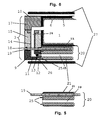
- the valve 3 shown in FIG. 6 is composed of a fixed valve part 9 and a rotatable winding body 10. Both parts consist, for example, of a body-friendly metal, such as titanium or a titanium alloy.
- the fixed valve part 9 contains a first pipe section 11, for example made of stainless steel, into which a metal valve seat 12 and, for example, a metal ball 13 are installed as a closure body.
- a second pipe section 14 connects to the pipe section 11 and leads into the chamber 1 of the hollow body 2. At the same time, it serves as a fixed bearing journal for the rotatable winding body 10. For reasons of assembly, this is divided into a lower part 15 surrounding the pipe section 14 and an upper part 17 intervenes, which consists for example of a glass fiber reinforced plastic.
- the drive belt 19 is part of an instrument 20 shown in FIG. 5 for inserting, winding up and filling the implant.
- the instrument 20 essentially consists of a metal guide piece 21 in which two longitudinal bores or channels 22 and 23 are provided. One 22 of these bores receives the drive belt 19, while the other 23, which can be connected to the pipe section 11 of the valve part 9, is provided for the supply of the incompressible filler, for example hydroxyl-ethyl methacrylate, into the chamber 1; the filler flows through the check valve consisting of the valve seat 12 and the closure body 13 via the flow path 24 in the pipe sections 11 and 14 and the upper part 17 of the chamber 1.
- the incompressible filler for example hydroxyl-ethyl methacrylate
- two pins 25 are provided in the end face of the guide piece 21, which pins can be inserted into corresponding recesses 26 in the valve part 9.
- the implant together with its guiding instrument 20 is accommodated in a tube 27 for the implantation.
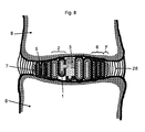
- the natural tissue of the annulus fibrosus, which surrounds the implant 1, is designated by 28 in FIG. 8.
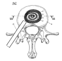
- the implant can be inserted between two vertebrae 8, for example, similarly to the implant mentioned above according to US Pat. No. 3,875,595, from the dorsal side through the tube 27, for the insertion of which between the vertebrae only a relatively minor intervention is necessary.
- the nucleus pulposus and possibly defective Parts of the annulus fibrosus are removed and then the implant, which has previously been rigidly connected to the instrument 20, is inserted through the tube 27 into the resulting cavity.
- the band-like part 2, 6, 7 of the implant is wound onto the valve by pulling on one side of the drive belt 19 designed as a closed ring.
- the free end 7 of the band is fixed on itself by welding or sewing and the belt 19 is cut and removed.
- the chamber 1 is now filled with the filling medium through the bore 23 in the guide piece 21. If the desired amount of filler is filled, the guide piece 21 is detached from the valve part 9 and removed through the tube 27. Finally, the tube 27 is removed from the body.
Abstract
Description
Die Erfindung betrifft ein Implantat, insbesondere eine Zwischenwirbelprothese, bestehend aus einem elastischen, flüssigkeitsdichten Hohlkörper, der mit einem inkompressiblen, fliessfähigen Medium gefüllt ist, sowie ein Instrument zum Einführen, Aufwickeln und Füllen des Implantates.The invention relates to an implant, in particular an intervertebral prosthesis, consisting of an elastic, liquid-tight hollow body which is filled with an incompressible, flowable medium, and an instrument for inserting, winding up and filling the implant.
Eine Zwischenwirbelprothese der vorstehend genannten Art ist beispielsweise aus der US-PS 3,875,595 bekannt. Bei dieser Konstruktion wird ein beschädigter Bandscheibenkern (nucleus pulposus) durch ein blasenartiges Kissen aus elastischem Material ersetzt, das mit einem inkompressiblen Medium gefüllt werden kann. Dabei bleibt der äussere Ring (anulus fibrosus) einer natürlichen Bandscheibe weitgehend erhalten. Darüberhinaus ist ein rohrförmiges Instrument vorgesehen, durch das hindurch das aufblasbare Implantat zunächst im nicht gefüllten Zustand implantiert, in den benachbarten Wirbeln "verankert" und anschliessend gefüllt wird. Bei dieser Konstruktion muss der anulus fibrosus die bei einer Belastung im Nucleus erzeugten Druckkräfte als radiale Kräfte vollständig aufnehmen.An intervertebral prosthesis of the type mentioned above is known, for example, from US Pat. No. 3,875,595. In this construction, a damaged intervertebral disc core (nucleus pulposus) is replaced by a bubble-like cushion made of elastic material that can be filled with an incompressible medium. The outer ring (anulus fibrosus) of a natural intervertebral disc is largely preserved. In addition, a tubular instrument is provided, through which the inflatable implant is initially implanted in the unfilled state, "anchored" in the adjacent vertebrae and then filled. At this The annulus fibrosus must completely absorb the compressive forces generated when the nucleus is loaded as radial forces.
In der EP-A-0 227 282 wird eine Zwischenwirbelprothese gezeigt und beschrieben, die ebenfalls aus einem hohlen Kissen besteht, das mit einem nicht kompressiblen Medium gefüllt ist. Diese Prothese ist auf ihren, den Wirbeln zugewandten Oberflächen mit einer Struktur versehen, in die zu ihrer Fixierung Knochengewebe einwächst. Durch sie wird die ganze Bandscheibe ersetzt, wofür eine relativ weite Oeffnung zwischen den Wirbeln von ventral her freigelegt werden muss, da diese Prothese im bereits gefüllten Zustand implantiert wird.EP-A-0 227 282 shows and describes an intervertebral prosthesis which also consists of a hollow cushion which is filled with a non-compressible medium. On its surfaces facing the vertebrae, this prosthesis is provided with a structure into which bone tissue grows in order to fix it. The entire intervertebral disc is replaced by them, for which purpose a relatively wide opening between the vertebrae must be exposed from the ventral side, since this prosthesis is implanted in the already filled state.
In der EP-A-0 176 728 wird eine Zwischenwirbelprothese beschrieben, die mit dem Gleitkörper ein fixes Drehzentrum definiert, was erwiesenermassen nicht den Tatsachen bei Bewegungsvorgängen in der Wirbelsäule entspricht. Dazu werden die Deckplatten in erhöhtem Masse belastet, was zu einem Einsinken des Implantates führen kann.EP-A-0 176 728 describes an intervertebral prosthesis which defines a fixed center of rotation with the sliding body, which has been proven not to correspond to the facts during movement processes in the spine. For this purpose, the cover plates are loaded to an increased extent, which can cause the implant to sink.
Aufgabe der Erfindung ist es, ein Implantat als Ersatz für den Nucleus einer Bandscheibe zu schaffen, bei dem die Nachteile der vorstehend geschilderten Konstruktionen vermieden sind; das zu schaffende Implantat soll dabei einerseits die radialen Kräfte, die über seine inkompressible Füllung auf seine Peripherie ausgeübt werden, aufnehmen, andererseits jedoch nur einen relativ geringfügigen Eingriff in den Zwischenwirbelbereich mit einer möglichst kleinen Oeffnung erfordern.The object of the invention is to provide an implant as a replacement for the nucleus of an intervertebral disc, in which the disadvantages of the constructions described above are avoided; the implant to be created should on the one hand absorb the radial forces which are exerted on its periphery via its incompressible filling, but on the other hand only require a relatively minor intervention in the intervertebral region with the smallest possible opening.
Diese Aufgabe wird mit der Erfindung dadurch gelöst, dass der Hohlkörper aus einer langgestreckten, flexiblen Kammer besteht, an deren einem Ende ein um eine Achse drehbares Ventil vorhanden ist, dass die Kammer ferner auf das Ventil aufwickelbar ist, und dass sich schliesslich das andere Ende der Kammer in einem kompakten Band fortsetzt.This object is achieved with the invention in that the hollow body consists of an elongated, flexible chamber, at one end of which there is a valve which can be rotated about an axis, that the chamber can also be wound onto the valve, and that finally the other end of the chamber continues in a compact band.
Mit dem Ventil voraus, über das eine Füllung nach dem Implantieren der Kammer erfolgt, wird die neue Konstruktion in den vom zuvor entfernten nucleus pulposus eingenommenen Raum eingeführt und durch Rotation des Ventils auf dieses aufgewickelt, ehe die Kammer gefüllt wird. Wie die Prothese nach dem US-Patent 3,875,595 kann das neue Implantat daher durch ein einfaches Rohr hindurch von dorsal implantiert werden, wofür ein durch dieses Rohr einführbares Instrument zum Einführen, Aufwickeln und Füllen des Implantes entwickelt worden ist, das seinerseits dadurch gekennzeichnet ist, dass es ein rohrartiges Führungsstück mit zwei axialen Kanälen aufweist, von denen einer für die Zufuhr des Füllmediums bestimmt ist, dass ferner das Führungsstück eine Einrichtung für einen lösbaren Anschluss an das Ventil aufweist, und dass schliesslich der zweite Kanal den Rotationsantrieb für den drehbaren Ventilteil enthält.With the valve ahead, which is used for filling after the chamber has been implanted, the new construction is introduced into the space occupied by the previously removed nucleus pulposus and wound onto it by rotating the valve before the chamber is filled. Like the prosthesis according to US Pat. No. 3,875,595, the new implant can therefore be implanted dorsally through a simple tube, for which purpose an instrument which can be inserted through this tube has been developed for inserting, winding up and filling the implant, which in turn is characterized in that it has a tubular guide piece with two axial channels, one of which is intended for the supply of the filling medium, the guide piece also has a device for a releasable connection to the valve, and finally the second channel contains the rotary drive for the rotatable valve part.
Die geforderte Fähigkeit, die radialen Kräfte aufzunehmen, wird durch das an die Kammer anschliessende kompakte Band erreicht, das die Kammer nach der Implantation mehrfach umschlingt und mit seinem Ende an diesen Umschlingungen fixiert ist.The required ability to absorb the radial forces is achieved by the compact belt adjoining the chamber, which wraps around the chamber several times after implantation and is fixed at its end to these wraps.
Die neue Konstruktion weist darüberhinaus keine fixierten Drehzentren auf. Weiterhin sind die Deckplatten wie beim natürlichen nucleus pulposus belastet. Schliesslich wird die Funktion des anulus fibrosus durch die neue Konstruktion unterstützt.The new design also has no fixed turning centers. As with the natural nucleus pulposus, the cover plates are also loaded. Eventually the function of the annulus fibrosus is supported by the new construction.
Mit Vorteil bestehen die Kammer und das Band aus einem Stück und aus einer textilen Struktur - d.h. beispielsweise einem Gewebe, Gewirk, Gestrick oder Geflecht -, die teilweise von einem Elastomer umhüllt ist, um Abrieb der Textilstruktur zu vermeiden. Weiterhin hat es sich als zweckmässig erwiesen, wenn die parallel zur Drehachse des Ventils verlaufende Höhe der Kammer grösser ist als ihre Breite, wobei der querschnitt beispielsweise mindestens nahezu rechteckig sein kann; durch diesen beiden Merkmale ergibt sich ein Wickelkörper, dessen Windungen mit relativ grossen glatten Auflageflächen aneinander liegen, wobei sich beim Aufwickeln einer Anzahl Windungen bildet, die ihrerseits eine Anpassung an die Form des Hohlraumes, in die Prothese eingelegt wird, erleichtern. Diese Anpassung kann noch weiter unterstützt werden, wenn die Höhe der Kammer variabel ist.Advantageously, the chamber and the band consist of one piece and of a textile structure - i.e. for example a fabric, knitted fabric, knitted fabric or braid - which is partially covered by an elastomer in order to avoid abrasion of the textile structure. Furthermore, it has proven to be expedient if the height of the chamber running parallel to the axis of rotation of the valve is greater than its width, it being possible for the cross section to be at least almost rectangular, for example; These two features result in a winding body, the turns of which lie against one another with relatively large smooth contact surfaces, with a number of turns being formed when winding, which in turn facilitates adaptation to the shape of the cavity into which the prosthesis is inserted. This adjustment can be further supported if the height of the chamber is variable.
Für das an einem Ende der Kammer angesetzte Ventil hat sich eine Konstruktion bewährt, die eine feststehende Basis mit einem ersten Rohrabschnitt aufweist, in dem ein Ventilsitz und ein Ventilkörper vorhanden sind, und von dem ein zweiter Rohrabschnitt, der als feststehender Lagerzapfen für einen drehbaren Aufwickelkörper dient, in die Kammer führt, deren eines Ende am Aufwickelkörper befestigt ist; der Aufwickelkörper kann dabei zusätzlich mit einem Zahnkranz für den Eingriff des Antriebs des Instrumentes versehen sein.For the valve attached to one end of the chamber, a design has proven itself which has a fixed base with a first tube section, in which a valve seat and a valve body are present, and of which a second tube section, which acts as a fixed bearing journal for a rotatable winding body serves, leads into the chamber, one end of which is attached to the winding body; the winding body can additionally be provided with a ring gear for engaging the drive of the instrument.
Bei diesem ist es zweckmässig, wenn die Einrichtung für den Anschluss des Ventilteils aus in den feststehenden Ventilteil eingreifenden Zapfen besteht, die aus der Stirnseite des Führungsstücks herausragen; weiterhin ist der Antrieb für die Rotation des Ventilsteils vorteilhafterweise ein geschlossener Riemen mit einer geriffelten Oberfläche, deren Riffelung in den Zahnkranz des Aufwickelkörpers eingreift.In this case it is expedient if the device for the connection of the valve part consists of pins which engage in the fixed valve part and which protrude from the end face of the guide piece; continues to be the drive for the rotation of the valve part advantageously a closed belt with a corrugated surface, the corrugation of which engages in the toothed ring of the winding body.
Im folgenden wird die Erfindung anhand eines Ausführungsbeispiels im Zusammenhang mit der Zeichnung näher erläutert.
- Fig. 1 zeigt schematisch den Hohlkörper des Implantates in abgewickelter Form;
- Fig. 2 - 4 sind Schnitt II-II bis IV-IV von Fig. 1;
- Fig. 5 gibt, ebenfalls in schematischer Darstellung, das Einführinstrument wieder;
- Fig. 6 zeigt schematisch das Einführinstrument mit daran angesetztem Ventil und Hohlkörper in dem Rohr, durch das hindurch die Implantation erfolgt;
- Fig. 7 stellt in einer Aufsicht auf einen Wirbelkörper das eingesetzte, aufgewickelte und gefüllte Implantat dar, während
- Fig. 8 ein Schnitt VIII-VIII von Fig. 7 ist.
- Fig. 1 shows schematically the hollow body of the implant in a developed form;
- Figs. 2-4 are sections II-II to IV-IV of Fig. 1;
- Fig. 5 shows, also in a schematic representation, the insertion instrument;
- Fig. 6 shows schematically the insertion instrument with attached valve and hollow body in the tube through which the implantation takes place;
- Fig. 7 shows a top view of a vertebral body, the inserted, wound and filled implant, while
- Figure 8 is a section VIII-VIII of Figure 7.
Ein Hohlraum oder eine Kammer 1 (Fig. 1) eines bandartigen Hohlkörpers 2 ist an einem Ende mit einem in Fig. 1 nur schematisch dargestellten Ventil 3 verbunden, dessen Aufbau später beschrieben wird. Der flexible Hohlkörper (Fig. 2) besteht aus einem, aus Kunststoff-Fäden, beispielsweise Polyethylen Terephthalat, gefertigten textilen Maschenwerk 4, das aussen mit einer Elastomerschicht 5, beispielsweise einem Polyurethan, mittels eines Tauchverfahrens beschichtet ist. Die Polyurethanschicht hat die Aufgabe, ein Reiben der Textilfäden aufeinander bei eingesetztem Implantat zu verhindern. Wie Fig. 1 zeigt, setzt sich die Kammer in einem kompakten textilen Band 6 fort (Fig. 3), das über eine gewisse Länge ebenfalls noch mit dem Elastomer 5 beschichtet ist, an seinem freien Ende 7 (Fig. 4) jedoch keine Beschichtung 5 mehr trägt. Das freie Ende 7 kann somit relativ einfach durch Vernähen oder Verschweissen bei einer zwischen zwei Wirbeln 8 (Fig. 7 und 8) implantierten Prothese auf sich selbst fixiert werden.A cavity or a chamber 1 (FIG. 1) of a band-like
Das in Fig. 6 gezeigte Ventil 3 setzt sich aus einem feststehenden Ventilteil 9 und einem drehbaren Aufwickelkörper 10 zusammen. Beide Teile bestehen beispielsweise aus einem körperfreundlichen Metall, wie Titan oder eine Titanlegierung. Der feststehende Ventilteil 9 enthält einen, beispielsweise aus rostfreiem Stahl bestehenden ersten Rohrabschnitt 11, in den ein metallener Ventilsitz 12 und als Verschlusskörper beispielsweise eine Metallkugel 13 eingebaut sind.The
An den Rohrabschnitt 11 schliesst sich ein zweiter Rohrabschnitt 14 an, der in die Kammer 1 des Hohlkörpers 2 führt. Er dient gleichzeitig als feststehender Lagerzapfen für den drehbaren Aufwickelkörper 10. Dieser ist aus Montagegründen unterteilt in einen den Rohrabschnitt 14 umgebenden Unterteil 15 und einen oberen Teil 17. An seinem Boden ist der Unterteil 15 als Zahnkranz 18 ausgebildet, in den als Rotationsantrieb ein Antriebsriemen 19 eingreift, der beispielsweise aus einem glasfaserverstärktem Kunststoff besteht.A
Der Antriebsriemen 19 ist ein Teil eines in Fig. 5 gezeigten Instrumentes 20 zum Einführen, Aufwickeln und Füllen des Implantates. Das Instrument 20 besteht in vorliegenden Beispiel im wesentlichen aus einem metallenen Führungsstück 21, in dem zwei Längsbohrungen oder Kanäle 22 und 23 vorgesehen sind. Die eine 22 dieser Bohrungen nimmt den Antriebsriemen 19 auf, während die andere 23, die an den Rohrabschnitt 11 des Ventilteils 9 anschliessbar ist, für die Zuführung des inkompressiblen Füllmittels, beispielsweise Hydroxin-Ethyl-Methacrylat, in die Kammer 1 vorgesehen ist; das Füllmittel fliesst dabei durch das aus Ventilsitz 12 und Verschlusskörper 13 bestehende Rückschlagventil über den Strömungsweg 24 in den Rohrabschnitten 11 und 14 und dem Oberteil 17 der Kammer 1 zu.The
Für eine starre, aber lösbare Verbindung des Führungsstücks 21 mit dem Ventilteil 9 sind in der Stirnsteite des Führungsstücks 21 zwei Zapfen 25 vorgesehen, die in entsprechende Ausnehmungen 26 im Ventilteil 9 einsteckbar sind.For a rigid but detachable connection of the
Das Implantat zusammen mit seinem Führungsinstrument 20 ist für die Implantation in einem Rohr 27 untergebracht.The implant together with its guiding
Mit 28 ist in Fig. 8 das natürliche Gewebe des anulus fibrosus bezeichnet, das das Implantat 1 umschliesst.The natural tissue of the annulus fibrosus, which surrounds the
Das Einsetzen des Implantates zwischen zwei Wirbel 8 kann beispielsweise ähnlich wie bei dem eingangs erwähnten Implantat nach dem US-Patent 3,875,595 von dorsal her durch das Rohr 27 hindurch erfolgen, für dessen Einführung zwischen die Wirbel nur ein relativ geringfügiger Eingriff notwendig ist. Nach dem "Setzen"'des Rohres 27 werden der nucleus pulposus und gegebenenfalls schadhafte Teile des anulus fibrosus entfernt und anschliessend das Implantat, das zuvor mit dem Instrument 20 starr verbunden worden ist, durch das Rohr 27 in den entstandenen Hohlraum eingeführt. Nachdem das Ventil 3 in die gewünschte Lage gebracht worden ist, wird der bandartige Teil 2, 6, 7 des Implantates durch Ziehen an einer Seite des als geschlossener Ring ausgebildeten Antriebsriemens 19 auf das Ventil aufgewickelt. Nach Beendigung des Wickelvorganges wird das freie Ende 7 des Bandes durch Schweissen oder Nähen auf sich selbst fixiert und der Riemen 19 aufgetrennt und entfernt. Nunmehr wird die Kammer 1 durch die Bohrung 23 im Führungstück 21 hindurch mit dem Füllmedium gefüllt. Ist die gewünschte Menge Füllmittel eingefüllt, so wird das Führungsstück 21 vom Ventilteil 9 gelöst und durch das Rohr 27 entfernt. Abschliessend entfernt man noch das Rohr 27 aus dem Körper.The implant can be inserted between two
Claims (10)
Priority Applications (1)
| Application Number | Priority Date | Filing Date | Title |
|---|---|---|---|
| AT91810173T ATE95409T1 (en) | 1990-04-20 | 1991-03-15 | IMPLANT, ESPECIALLY INTERVERBAL PROSTHESES. |
Applications Claiming Priority (2)
| Application Number | Priority Date | Filing Date | Title |
|---|---|---|---|
| CH1324/90 | 1990-04-20 | ||
| CH132490 | 1990-04-20 |
Publications (2)
| Publication Number | Publication Date |
|---|---|
| EP0453393A1 true EP0453393A1 (en) | 1991-10-23 |
| EP0453393B1 EP0453393B1 (en) | 1993-10-06 |
Family
ID=4207784
Family Applications (1)
| Application Number | Title | Priority Date | Filing Date |
|---|---|---|---|
| EP91810173A Expired - Lifetime EP0453393B1 (en) | 1990-04-20 | 1991-03-15 | Implant, particularly intervertebral prosthesis |
Country Status (4)
| Country | Link |
|---|---|
| US (1) | US5171280A (en) |
| EP (1) | EP0453393B1 (en) |
| AT (1) | ATE95409T1 (en) |
| DE (1) | DE59100448D1 (en) |
Cited By (12)
| Publication number | Priority date | Publication date | Assignee | Title |
|---|---|---|---|---|
| US5306307A (en) * | 1991-07-22 | 1994-04-26 | Calcitek, Inc. | Spinal disk implant |
| FR2712486A1 (en) * | 1993-11-19 | 1995-05-24 | Breslave Patrice | Intervertebral prosthesis |
| EP0700671A1 (en) * | 1994-09-08 | 1996-03-13 | Howmedica Inc. | Hydrogel intervertebral disc nucleus |
| DE19519101A1 (en) * | 1995-05-24 | 1996-11-28 | Harms Juergen | Height-adjustable vertebral body replacement |
| EP0773008A1 (en) | 1995-11-08 | 1997-05-14 | Sulzer Orthopädie AG | Intervertebral prosthesis |
| DE19710392C1 (en) * | 1997-03-13 | 1999-07-01 | Haehnel Michael | Slipped disc implant comprises an extensible, hinged or wound body |
| WO2005092247A1 (en) * | 2004-03-26 | 2005-10-06 | Nuvasive Inc. | Prosthetic spinal disc |
| FR2885032A1 (en) * | 2005-04-29 | 2006-11-03 | Sdgi Holdings Inc | Kit for executing spinal implantation procedure, comprises a tubular device, a conveyor with a netted transmitting rod, and a structured deformable prosthesis |
| US7942104B2 (en) | 2007-01-22 | 2011-05-17 | Nuvasive, Inc. | 3-dimensional embroidery structures via tension shaping |
| US7946236B2 (en) | 2007-01-31 | 2011-05-24 | Nuvasive, Inc. | Using zigzags to create three-dimensional embroidered structures |
| US8282681B2 (en) | 2007-08-13 | 2012-10-09 | Nuvasive, Inc. | Bioresorbable spinal implant and related methods |
| US8377135B1 (en) | 2008-03-31 | 2013-02-19 | Nuvasive, Inc. | Textile-based surgical implant and related methods |
Families Citing this family (342)
| Publication number | Priority date | Publication date | Assignee | Title |
|---|---|---|---|---|
| EP0621020A1 (en) * | 1993-04-21 | 1994-10-26 | SULZER Medizinaltechnik AG | Intervertebral prosthesis and method of implanting such a prosthesis |
| US5514180A (en) * | 1994-01-14 | 1996-05-07 | Heggeness; Michael H. | Prosthetic intervertebral devices |
| US5888220A (en) * | 1994-05-06 | 1999-03-30 | Advanced Bio Surfaces, Inc. | Articulating joint repair |
| US6248131B1 (en) | 1994-05-06 | 2001-06-19 | Advanced Bio Surfaces, Inc. | Articulating joint repair |
| US5571189A (en) * | 1994-05-20 | 1996-11-05 | Kuslich; Stephen D. | Expandable fabric implant for stabilizing the spinal motion segment |
| US5824093A (en) * | 1994-10-17 | 1998-10-20 | Raymedica, Inc. | Prosthetic spinal disc nucleus |
| DE69532856T2 (en) * | 1994-10-17 | 2005-04-21 | Raymedica Inc | Spinal disc-GRAFT |
| US5674296A (en) | 1994-11-14 | 1997-10-07 | Spinal Dynamics Corporation | Human spinal disc prosthesis |
| US5645597A (en) * | 1995-12-29 | 1997-07-08 | Krapiva; Pavel I. | Disc replacement method and apparatus |
| US5716416A (en) * | 1996-09-10 | 1998-02-10 | Lin; Chih-I | Artificial intervertebral disk and method for implanting the same |
| EP1230902A1 (en) | 1996-11-15 | 2002-08-14 | Advanced Bio Surfaces, Inc. | Biomaterial system for in situ tissue repair |
| US20080086212A1 (en) | 1997-01-02 | 2008-04-10 | St. Francis Medical Technologies, Inc. | Spine distraction implant |
| US6022376A (en) * | 1997-06-06 | 2000-02-08 | Raymedica, Inc. | Percutaneous prosthetic spinal disc nucleus and method of manufacture |
| GB9713330D0 (en) * | 1997-06-25 | 1997-08-27 | Bridport Gundry Plc | Surgical implant |
| GB9714580D0 (en) * | 1997-07-10 | 1997-09-17 | Wardlaw Douglas | Prosthetic intervertebral disc nucleus |
| US6132465A (en) * | 1998-06-04 | 2000-10-17 | Raymedica, Inc. | Tapered prosthetic spinal disc nucleus |
| US6296664B1 (en) | 1998-06-17 | 2001-10-02 | Surgical Dynamics, Inc. | Artificial intervertebral disc |
| ATE363877T1 (en) | 1998-07-22 | 2007-06-15 | Warsaw Orthopedic Inc | SCREWED CYLINDRICAL MULTIDISCOID SINGLE OR MULTIPLE NETWORK PLATE PROSTHESIS |
| US6506936B1 (en) * | 1999-02-25 | 2003-01-14 | Fibrogen, Inc. | N-substituted arylsulfonylamino hydroxamic acids useful as inhibitors of c-proteinase and for treating or preventing disorders related to unregulated collagen production |
| CA2363254C (en) | 1999-03-07 | 2009-05-05 | Discure Ltd. | Method and apparatus for computerized surgery |
| US6602291B1 (en) | 1999-04-05 | 2003-08-05 | Raymedica, Inc. | Prosthetic spinal disc nucleus having a shape change characteristic |
| US6110210A (en) * | 1999-04-08 | 2000-08-29 | Raymedica, Inc. | Prosthetic spinal disc nucleus having selectively coupled bodies |
| US6428576B1 (en) * | 1999-04-16 | 2002-08-06 | Endospine, Ltd. | System for repairing inter-vertebral discs |
| US6733505B2 (en) | 2000-04-26 | 2004-05-11 | Sdgi Holdings, Inc. | Apparatus and method for loading a prosthetic nucleus into a deployment cannula to replace the nucleus pulposus of an intervertebral disc |
| US6764514B1 (en) * | 1999-04-26 | 2004-07-20 | Sdgi Holdings, Inc. | Prosthetic apparatus and method |
| US7081120B2 (en) * | 1999-04-26 | 2006-07-25 | Sdgi Holdings, Inc. | Instrumentation and method for delivering an implant into a vertebral space |
| US6969404B2 (en) * | 1999-10-08 | 2005-11-29 | Ferree Bret A | Annulus fibrosis augmentation methods and apparatus |
| US7273497B2 (en) | 1999-05-28 | 2007-09-25 | Anova Corp. | Methods for treating a defect in the annulus fibrosis |
| US20060247665A1 (en) | 1999-05-28 | 2006-11-02 | Ferree Bret A | Methods and apparatus for treating disc herniation and preventing the extrusion of interbody bone graft |
| US6419704B1 (en) | 1999-10-08 | 2002-07-16 | Bret Ferree | Artificial intervertebral disc replacement methods and apparatus |
| US20070038231A1 (en) | 1999-05-28 | 2007-02-15 | Ferree Bret A | Methods and apparatus for treating disc herniation and preventing the extrusion of interbody bone graft |
| EP1185221B1 (en) | 1999-06-04 | 2005-03-23 | SDGI Holdings, Inc. | Artificial disc implant |
| US6936071B1 (en) | 1999-07-02 | 2005-08-30 | Spine Solutions, Inc. | Intervertebral implant |
| NL1012719C1 (en) | 1999-07-28 | 2001-01-30 | Veldhuizen Dr Ag | Spine prosthesis. |
| FR2797179B1 (en) * | 1999-08-03 | 2002-03-08 | Michel Gau | INTERVERTEBRAL NUCLEAR PROSTHESIS AND SURGICAL IMPLANTATION METHOD |
| US7435260B2 (en) | 1999-08-13 | 2008-10-14 | Ferree Bret A | Use of morphogenetic proteins to treat human disc disease |
| US6454804B1 (en) | 1999-10-08 | 2002-09-24 | Bret A. Ferree | Engineered tissue annulus fibrosis augmentation methods and apparatus |
| US6685695B2 (en) * | 1999-08-13 | 2004-02-03 | Bret A. Ferree | Method and apparatus for providing nutrition to intervertebral disc tissue |
| US7201776B2 (en) * | 1999-10-08 | 2007-04-10 | Ferree Bret A | Artificial intervertebral disc replacements with endplates |
| US6793677B2 (en) * | 1999-08-13 | 2004-09-21 | Bret A. Ferree | Method of providing cells and other biologic materials for transplantation |
| US6755863B2 (en) * | 1999-10-08 | 2004-06-29 | Bret A. Ferree | Rotator cuff repair using engineered tissues |
| US7717961B2 (en) | 1999-08-18 | 2010-05-18 | Intrinsic Therapeutics, Inc. | Apparatus delivery in an intervertebral disc |
| US7220281B2 (en) | 1999-08-18 | 2007-05-22 | Intrinsic Therapeutics, Inc. | Implant for reinforcing and annulus fibrosis |
| US6821276B2 (en) * | 1999-08-18 | 2004-11-23 | Intrinsic Therapeutics, Inc. | Intervertebral diagnostic and manipulation device |
| US7998213B2 (en) | 1999-08-18 | 2011-08-16 | Intrinsic Therapeutics, Inc. | Intervertebral disc herniation repair |
| EP1624832A4 (en) | 1999-08-18 | 2008-12-24 | Intrinsic Therapeutics Inc | Devices and method for augmenting a vertebral disc nucleus |
| EP1328221B1 (en) | 1999-08-18 | 2009-03-25 | Intrinsic Therapeutics, Inc. | Devices for nucleus pulposus augmentation and retention |
| US7553329B2 (en) | 1999-08-18 | 2009-06-30 | Intrinsic Therapeutics, Inc. | Stabilized intervertebral disc barrier |
| US6936072B2 (en) * | 1999-08-18 | 2005-08-30 | Intrinsic Therapeutics, Inc. | Encapsulated intervertebral disc prosthesis and methods of manufacture |
| US6425919B1 (en) * | 1999-08-18 | 2002-07-30 | Intrinsic Orthopedics, Inc. | Devices and methods of vertebral disc augmentation |
| US8323341B2 (en) | 2007-09-07 | 2012-12-04 | Intrinsic Therapeutics, Inc. | Impaction grafting for vertebral fusion |
| US7972337B2 (en) | 2005-12-28 | 2011-07-05 | Intrinsic Therapeutics, Inc. | Devices and methods for bone anchoring |
| US20040024465A1 (en) * | 1999-08-18 | 2004-02-05 | Gregory Lambrecht | Devices and method for augmenting a vertebral disc |
| EP1779815A3 (en) | 1999-09-14 | 2007-06-27 | Spine Solutions Inc. | Insert instrument for an implant between vertebrae |
| US6436119B1 (en) | 1999-09-30 | 2002-08-20 | Raymedica, Inc. | Adjustable surgical dilator |
| US6264695B1 (en) * | 1999-09-30 | 2001-07-24 | Replication Medical, Inc. | Spinal nucleus implant |
| US7060100B2 (en) * | 1999-10-08 | 2006-06-13 | Ferree Bret A | Artificial disc and joint replacements with modular cushioning components |
| US6645247B2 (en) * | 1999-10-08 | 2003-11-11 | Bret A. Ferree | Supplementing engineered annulus tissues with autograft of allograft tendons |
| US8679180B2 (en) * | 1999-10-08 | 2014-03-25 | Anova Corporation | Devices used to treat disc herniation and attachment mechanisms therefore |
| US7201774B2 (en) * | 1999-10-08 | 2007-04-10 | Ferree Bret A | Artificial intervertebral disc replacements incorporating reinforced wall sections |
| US20030026788A1 (en) * | 1999-10-08 | 2003-02-06 | Ferree Bret A. | Use of extracellular matrix tissue to preserve cultured cell phenotype |
| US20040172019A1 (en) * | 1999-10-08 | 2004-09-02 | Ferree Bret A. | Reinforcers for artificial disc replacement methods and apparatus |
| US6648920B2 (en) * | 1999-10-08 | 2003-11-18 | Bret A. Ferree | Natural and synthetic supplements to engineered annulus and disc tissues |
| US6648919B2 (en) * | 1999-10-14 | 2003-11-18 | Bret A. Ferree | Transplantation of engineered meniscus tissue to the intervertebral disc |
| US7004970B2 (en) | 1999-10-20 | 2006-02-28 | Anulex Technologies, Inc. | Methods and devices for spinal disc annulus reconstruction and repair |
| US8128698B2 (en) | 1999-10-20 | 2012-03-06 | Anulex Technologies, Inc. | Method and apparatus for the treatment of the intervertebral disc annulus |
| US7951201B2 (en) | 1999-10-20 | 2011-05-31 | Anulex Technologies, Inc. | Method and apparatus for the treatment of the intervertebral disc annulus |
| US7935147B2 (en) | 1999-10-20 | 2011-05-03 | Anulex Technologies, Inc. | Method and apparatus for enhanced delivery of treatment device to the intervertebral disc annulus |
| US6592625B2 (en) | 1999-10-20 | 2003-07-15 | Anulex Technologies, Inc. | Spinal disc annulus reconstruction method and spinal disc annulus stent |
| US7052516B2 (en) | 1999-10-20 | 2006-05-30 | Anulex Technologies, Inc. | Spinal disc annulus reconstruction method and deformable spinal disc annulus stent |
| US8632590B2 (en) | 1999-10-20 | 2014-01-21 | Anulex Technologies, Inc. | Apparatus and methods for the treatment of the intervertebral disc |
| US7615076B2 (en) | 1999-10-20 | 2009-11-10 | Anulex Technologies, Inc. | Method and apparatus for the treatment of the intervertebral disc annulus |
| US7691145B2 (en) | 1999-10-22 | 2010-04-06 | Facet Solutions, Inc. | Prostheses, systems and methods for replacement of natural facet joints with artificial facet joint surfaces |
| US8187303B2 (en) | 2004-04-22 | 2012-05-29 | Gmedelaware 2 Llc | Anti-rotation fixation element for spinal prostheses |
| US6974478B2 (en) * | 1999-10-22 | 2005-12-13 | Archus Orthopedics, Inc. | Prostheses, systems and methods for replacement of natural facet joints with artificial facet joint surfaces |
| US7674293B2 (en) | 2004-04-22 | 2010-03-09 | Facet Solutions, Inc. | Crossbar spinal prosthesis having a modular design and related implantation methods |
| EP1223872B2 (en) * | 1999-10-22 | 2007-09-26 | Archus Orthopedics Inc. | Facet arthroplasty devices |
| AU778410B2 (en) * | 1999-12-01 | 2004-12-02 | Henry Graf | Intervertebral stabilising device |
| US7744599B2 (en) | 2000-02-16 | 2010-06-29 | Trans1 Inc. | Articulating spinal implant |
| US6899716B2 (en) | 2000-02-16 | 2005-05-31 | Trans1, Inc. | Method and apparatus for spinal augmentation |
| US6740093B2 (en) | 2000-02-28 | 2004-05-25 | Stephen Hochschuler | Method and apparatus for treating a vertebral body |
| US6402750B1 (en) * | 2000-04-04 | 2002-06-11 | Spinlabs, Llc | Devices and methods for the treatment of spinal disorders |
| US6805695B2 (en) | 2000-04-04 | 2004-10-19 | Spinalabs, Llc | Devices and methods for annular repair of intervertebral discs |
| US6579291B1 (en) | 2000-10-10 | 2003-06-17 | Spinalabs, Llc | Devices and methods for the treatment of spinal disorders |
| US6689125B1 (en) | 2000-04-04 | 2004-02-10 | Spinalabs, Llc | Devices and methods for the treatment of spinal disorders |
| US20030040800A1 (en) * | 2000-04-26 | 2003-02-27 | Li Lehmann K. | Apparatus and method for replacing the nucleus pulposus of an intervertebral disc or for replacing an entire intervertebral disc |
| US6482234B1 (en) * | 2000-04-26 | 2002-11-19 | Pearl Technology Holdings, Llc | Prosthetic spinal disc |
| DE10024922C1 (en) * | 2000-05-19 | 2002-01-10 | Roland Minda | Artificial intervertebral disc |
| US20030135216A1 (en) * | 2000-05-25 | 2003-07-17 | Sevrain Lionel C. | Anchoring system for fixing objects to bones |
| US20030229348A1 (en) * | 2000-05-25 | 2003-12-11 | Sevrain Lionel C. | Auxiliary vertebrae connecting device |
| WO2001089428A2 (en) | 2000-05-25 | 2001-11-29 | Neurortho Implants Design, Llc | Inter-vertebral disc prosthesis for rachis for an anterior surgery thereof |
| US6533817B1 (en) | 2000-06-05 | 2003-03-18 | Raymedica, Inc. | Packaged, partially hydrated prosthetic disc nucleus |
| US6821277B2 (en) | 2000-06-23 | 2004-11-23 | University Of Southern California Patent And Copyright Administration | Percutaneous vertebral fusion system |
| US6749614B2 (en) | 2000-06-23 | 2004-06-15 | Vertelink Corporation | Formable orthopedic fixation system with cross linking |
| US6964667B2 (en) * | 2000-06-23 | 2005-11-15 | Sdgi Holdings, Inc. | Formed in place fixation system with thermal acceleration |
| US6899713B2 (en) | 2000-06-23 | 2005-05-31 | Vertelink Corporation | Formable orthopedic fixation system |
| US6875212B2 (en) | 2000-06-23 | 2005-04-05 | Vertelink Corporation | Curable media for implantable medical device |
| DE60141653D1 (en) * | 2000-07-21 | 2010-05-06 | Spineology Group Llc | A STRONG, POROUS NET BAG DEVICE AND ITS USE IN BONE SURGERY |
| US20080086133A1 (en) * | 2003-05-16 | 2008-04-10 | Spineology | Expandable porous mesh bag device and methods of use for reduction, filling, fixation and supporting of bone |
| US7601174B2 (en) | 2000-08-08 | 2009-10-13 | Warsaw Orthopedic, Inc. | Wear-resistant endoprosthetic devices |
| EP1363565A2 (en) | 2000-08-08 | 2003-11-26 | SDGI Holdings, Inc. | Implantable joint prosthesis |
| DE60140004D1 (en) | 2000-08-08 | 2009-11-05 | Warsaw Orthopedic Inc | DEVICE FOR STEREOTAKTIC IMPLANTATION |
| JP2004507318A (en) | 2000-08-30 | 2004-03-11 | エスディージーアイ・ホールディングス・インコーポレーテッド | Disc nucleus pulposus implant and method |
| US20020026244A1 (en) * | 2000-08-30 | 2002-02-28 | Trieu Hai H. | Intervertebral disc nucleus implants and methods |
| US20050154463A1 (en) * | 2000-08-30 | 2005-07-14 | Trieu Hal H. | Spinal nucleus replacement implants and methods |
| US7503936B2 (en) | 2000-08-30 | 2009-03-17 | Warsaw Orthopedic, Inc. | Methods for forming and retaining intervertebral disc implants |
| US6620196B1 (en) | 2000-08-30 | 2003-09-16 | Sdgi Holdings, Inc. | Intervertebral disc nucleus implants and methods |
| US7204851B2 (en) * | 2000-08-30 | 2007-04-17 | Sdgi Holdings, Inc. | Method and apparatus for delivering an intervertebral disc implant |
| AU2001293581A1 (en) * | 2000-09-26 | 2002-04-08 | Neurortho Implants Design, Llc | Inter-vertebral disc prosthesis for lumbar rachis through posterior surgery thereof |
| WO2002030338A1 (en) * | 2000-10-10 | 2002-04-18 | Vertx, Inc. | Method and appartus for treating a vertebral body |
| CA2323252C (en) * | 2000-10-12 | 2007-12-11 | Biorthex Inc. | Artificial disc |
| US20020045942A1 (en) * | 2000-10-16 | 2002-04-18 | Ham Michael J. | Procedure for repairing damaged discs |
| US6733531B1 (en) | 2000-10-20 | 2004-05-11 | Sdgi Holdings, Inc. | Anchoring devices and implants for intervertebral disc augmentation |
| ATE426376T1 (en) * | 2000-10-25 | 2009-04-15 | Intrinsic Therapeutics Inc | DEVICES FOR STRENGTHENING AND RETENTION OF THE NUCLEUS PULPOSUS |
| US6579319B2 (en) | 2000-11-29 | 2003-06-17 | Medicinelodge, Inc. | Facet joint replacement |
| US6565605B2 (en) | 2000-12-13 | 2003-05-20 | Medicinelodge, Inc. | Multiple facet joint replacement |
| US6419703B1 (en) | 2001-03-01 | 2002-07-16 | T. Wade Fallin | Prosthesis for the replacement of a posterior element of a vertebra |
| US6562045B2 (en) | 2001-02-13 | 2003-05-13 | Sdgi Holdings, Inc. | Machining apparatus |
| WO2002065954A1 (en) | 2001-02-16 | 2002-08-29 | Queen's University At Kingston | Method and device for treating scoliosis |
| US7090698B2 (en) | 2001-03-02 | 2006-08-15 | Facet Solutions | Method and apparatus for spine joint replacement |
| US6632235B2 (en) | 2001-04-19 | 2003-10-14 | Synthes (U.S.A.) | Inflatable device and method for reducing fractures in bone and in treating the spine |
| US7314467B2 (en) | 2002-04-24 | 2008-01-01 | Medical Device Advisory Development Group, Llc. | Multi selective axis spinal fixation system |
| US6770075B2 (en) | 2001-05-17 | 2004-08-03 | Robert S. Howland | Spinal fixation apparatus with enhanced axial support and methods for use |
| WO2003002040A1 (en) * | 2001-06-27 | 2003-01-09 | Mathys Medizinaltechnik Ag | Intervertebral disk prosthesis |
| US7156877B2 (en) * | 2001-06-29 | 2007-01-02 | The Regents Of The University Of California | Biodegradable/bioactive nucleus pulposus implant and method for treating degenerated intervertebral discs |
| US20090234457A1 (en) * | 2001-06-29 | 2009-09-17 | The Regents Of The University Of California | Systems, devices and methods for treatment of intervertebral disorders |
| US7819918B2 (en) * | 2001-07-16 | 2010-10-26 | Depuy Products, Inc. | Implantable tissue repair device |
| US6375682B1 (en) * | 2001-08-06 | 2002-04-23 | Lewis W. Fleischmann | Collapsible, rotatable and expandable spinal hydraulic prosthetic device |
| EP1437989A2 (en) * | 2001-08-27 | 2004-07-21 | James C. Thomas, Jr. | Expandable implant for partial disc replacement and reinforcement of a disc partially removed in a discectomy and for reduction and maintenance of alignment of cancellous bone fractures and methods and apparatuses for same. |
| US20040024463A1 (en) * | 2001-08-27 | 2004-02-05 | Thomas James C. | Expandable implant for partial disc replacement and reinforcement of a disc partially removed in a discectomy and for reduction and maintenance of alignment of cancellous bone fractures and methods and apparatuses for same |
| US7025787B2 (en) | 2001-11-26 | 2006-04-11 | Sdgi Holdings, Inc. | Implantable joint prosthesis and associated instrumentation |
| JP2005511207A (en) * | 2001-12-10 | 2005-04-28 | コルバー・ライフサイエンス・リミテッド | Intervertebral disc treatment methods, devices, and preparations |
| US20030171812A1 (en) * | 2001-12-31 | 2003-09-11 | Ilan Grunberg | Minimally invasive modular support implant device and method |
| ATE362354T1 (en) * | 2002-04-04 | 2007-06-15 | Synthes Gmbh | DISC PROSTHESIS OR NUCLEUS REPLACEMENT PROSTHESIS |
| US20040049283A1 (en) * | 2002-06-04 | 2004-03-11 | Tushar Patel | Medical implant and method of reducing back pain |
| US6793678B2 (en) | 2002-06-27 | 2004-09-21 | Depuy Acromed, Inc. | Prosthetic intervertebral motion disc having dampening |
| CA2495404C (en) | 2002-08-15 | 2011-05-03 | Justin K. Coppes | Intervertebral disc implant |
| JP4456481B2 (en) | 2002-08-15 | 2010-04-28 | ガーバー,デイヴィッド | Controlled artificial disc implant |
| EP1536743A2 (en) | 2002-08-27 | 2005-06-08 | SDGI Holdings, Inc. | Systems and methods for intravertebral reduction |
| GB0221527D0 (en) * | 2002-09-17 | 2002-10-23 | Depuy Int Ltd | Spinal implantation device |
| DE60331955D1 (en) | 2002-09-24 | 2010-05-12 | Bogomir Gorensek | STABILIZATION DEVICE FOR BELTS AND METHOD THEREFOR |
| US7083649B2 (en) | 2002-10-29 | 2006-08-01 | St. Francis Medical Technologies, Inc. | Artificial vertebral disk replacement implant with translating pivot point |
| US6966929B2 (en) | 2002-10-29 | 2005-11-22 | St. Francis Medical Technologies, Inc. | Artificial vertebral disk replacement implant with a spacer |
| US7497859B2 (en) | 2002-10-29 | 2009-03-03 | Kyphon Sarl | Tools for implanting an artificial vertebral disk |
| US7273496B2 (en) | 2002-10-29 | 2007-09-25 | St. Francis Medical Technologies, Inc. | Artificial vertebral disk replacement implant with crossbar spacer and method |
| JP2006505331A (en) | 2002-11-05 | 2006-02-16 | スパインオロジー,インク. | Semi-artificial intervertebral disc replacement system |
| US6974479B2 (en) * | 2002-12-10 | 2005-12-13 | Sdgi Holdings, Inc. | System and method for blocking and/or retaining a prosthetic spinal implant |
| US20040210310A1 (en) * | 2002-12-10 | 2004-10-21 | Trieu Hai H. | Implant system and method for intervertebral disc augmentation |
| US7204852B2 (en) | 2002-12-13 | 2007-04-17 | Spine Solutions, Inc. | Intervertebral implant, insertion tool and method of inserting same |
| CA2513680A1 (en) * | 2003-01-17 | 2004-08-05 | Psinergi Corporation | Artificial nucleus pulposus and method of injecting same |
| AU2004212942A1 (en) | 2003-02-14 | 2004-09-02 | Depuy Spine, Inc. | In-situ formed intervertebral fusion device |
| IL155146A0 (en) * | 2003-03-30 | 2003-10-31 | Expandis Ltd | Minimally invasive distraction device and method |
| US6981989B1 (en) | 2003-04-22 | 2006-01-03 | X-Pantu-Flex Drd Limited Liability Company | Rotatable and reversibly expandable spinal hydraulic prosthetic device |
| US7419505B2 (en) * | 2003-04-22 | 2008-09-02 | Fleischmann Lewis W | Collapsible, rotatable, and tiltable hydraulic spinal disc prosthesis system with selectable modular components |
| US7491204B2 (en) | 2003-04-28 | 2009-02-17 | Spine Solutions, Inc. | Instruments and method for preparing an intervertebral space for receiving an artificial disc implant |
| US7608104B2 (en) | 2003-05-14 | 2009-10-27 | Archus Orthopedics, Inc. | Prostheses, tools and methods for replacement of natural facet joints with artifical facet joint surfaces |
| US20040230304A1 (en) | 2003-05-14 | 2004-11-18 | Archus Orthopedics Inc. | Prostheses, tools and methods for replacement of natural facet joints with artifical facet joint surfaces |
| CA2527964A1 (en) * | 2003-06-02 | 2004-12-16 | Sdgi Holdings, Inc. | Intervertebral disc implants and methods for manufacturing and using same |
| US20040249459A1 (en) * | 2003-06-02 | 2004-12-09 | Ferree Bret A. | Nucleus replacements with asymmetrical stiffness |
| US20040260300A1 (en) | 2003-06-20 | 2004-12-23 | Bogomir Gorensek | Method of delivering an implant through an annular defect in an intervertebral disc |
| AU2004249291B2 (en) | 2003-06-20 | 2009-07-23 | Intrinsic Therapeutics, Inc. | Device and method for delivering an implant through an annular defect in an intervertebral disc |
| US7074238B2 (en) | 2003-07-08 | 2006-07-11 | Archus Orthopedics, Inc. | Prostheses, tools and methods for replacement of natural facet joints with artificial facet joint surfaces |
| US7803162B2 (en) | 2003-07-21 | 2010-09-28 | Spine Solutions, Inc. | Instruments and method for inserting an intervertebral implant |
| AU2004283727A1 (en) | 2003-10-23 | 2005-05-06 | Trans1 Inc. | Tools and tool kits for performing minimally invasive procedures on the spine |
| US7520899B2 (en) | 2003-11-05 | 2009-04-21 | Kyphon Sarl | Laterally insertable artificial vertebral disk replacement implant with crossbar spacer |
| US7670377B2 (en) | 2003-11-21 | 2010-03-02 | Kyphon Sarl | Laterally insertable artifical vertebral disk replacement implant with curved spacer |
| US20050209603A1 (en) | 2003-12-02 | 2005-09-22 | St. Francis Medical Technologies, Inc. | Method for remediation of intervertebral disks |
| US20050154462A1 (en) | 2003-12-02 | 2005-07-14 | St. Francis Medical Technologies, Inc. | Laterally insertable artificial vertebral disk replacement implant with translating pivot point |
| US7217291B2 (en) | 2003-12-08 | 2007-05-15 | St. Francis Medical Technologies, Inc. | System and method for replacing degenerated spinal disks |
| US7588590B2 (en) | 2003-12-10 | 2009-09-15 | Facet Solutions, Inc | Spinal facet implant with spherical implant apposition surface and bone bed and methods of use |
| US20050131406A1 (en) | 2003-12-15 | 2005-06-16 | Archus Orthopedics, Inc. | Polyaxial adjustment of facet joint prostheses |
| US7846183B2 (en) | 2004-02-06 | 2010-12-07 | Spinal Elements, Inc. | Vertebral facet joint prosthesis and method of fixation |
| US7993373B2 (en) | 2005-02-22 | 2011-08-09 | Hoy Robert W | Polyaxial orthopedic fastening apparatus |
| US8562649B2 (en) | 2004-02-17 | 2013-10-22 | Gmedelaware 2 Llc | System and method for multiple level facet joint arthroplasty and fusion |
| US8353933B2 (en) | 2007-04-17 | 2013-01-15 | Gmedelaware 2 Llc | Facet joint replacement |
| US8523904B2 (en) | 2004-03-09 | 2013-09-03 | The Board Of Trustees Of The Leland Stanford Junior University | Methods and systems for constraint of spinous processes with attachment |
| US7458981B2 (en) | 2004-03-09 | 2008-12-02 | The Board Of Trustees Of The Leland Stanford Junior University | Spinal implant and method for restricting spinal flexion |
| WO2005092248A1 (en) * | 2004-03-26 | 2005-10-06 | Nuvasive Inc. | Porous implant for spinal disc nucleus replacement |
| US7051451B2 (en) | 2004-04-22 | 2006-05-30 | Archus Orthopedics, Inc. | Facet joint prosthesis measurement and implant tools |
| US7406775B2 (en) | 2004-04-22 | 2008-08-05 | Archus Orthopedics, Inc. | Implantable orthopedic device component selection instrument and methods |
| US20080269900A1 (en) * | 2004-05-20 | 2008-10-30 | Christopher Reah | Surgical Implants |
| US7588578B2 (en) | 2004-06-02 | 2009-09-15 | Facet Solutions, Inc | Surgical measurement systems and methods |
| US8764801B2 (en) | 2005-03-28 | 2014-07-01 | Gmedelaware 2 Llc | Facet joint implant crosslinking apparatus and method |
| US20050278023A1 (en) * | 2004-06-10 | 2005-12-15 | Zwirkoski Paul A | Method and apparatus for filling a cavity |
| US9504583B2 (en) | 2004-06-10 | 2016-11-29 | Spinal Elements, Inc. | Implant and method for facet immobilization |
| JP2008510518A (en) | 2004-08-18 | 2008-04-10 | アーカス・オーソペディクス・インコーポレーテッド | Adjoint level articulating device, spinal stabilization system and method |
| US20060052870A1 (en) * | 2004-09-09 | 2006-03-09 | Ferree Bret A | Methods and apparatus to prevent movement through artificial disc replacements |
| US7303074B2 (en) * | 2004-09-22 | 2007-12-04 | Dombrowski Trudy M | Foldable organizer device |
| US7481840B2 (en) | 2004-09-29 | 2009-01-27 | Kyphon Sarl | Multi-piece artificial spinal disk replacement device with selectably positioning articulating element |
| US7575600B2 (en) | 2004-09-29 | 2009-08-18 | Kyphon Sarl | Artificial vertebral disk replacement implant with translating articulation contact surface and method |
| US20060089719A1 (en) * | 2004-10-21 | 2006-04-27 | Trieu Hai H | In situ formation of intervertebral disc implants |
| EP1809214B1 (en) | 2004-10-25 | 2017-07-12 | Gmedelaware 2 LLC | Spinal prothesis having a modular design |
| US8029540B2 (en) | 2005-05-10 | 2011-10-04 | Kyphon Sarl | Inter-cervical facet implant with implantation tool |
| US8100944B2 (en) * | 2004-12-13 | 2012-01-24 | Kyphon Sarl | Inter-cervical facet implant and method for preserving the tissues surrounding the facet joint |
| US20060247633A1 (en) | 2004-12-13 | 2006-11-02 | St. Francis Medical Technologies, Inc. | Inter-cervical facet implant with surface enhancements |
| US20060247650A1 (en) | 2004-12-13 | 2006-11-02 | St. Francis Medical Technologies, Inc. | Inter-cervical facet joint fusion implant |
| US8066749B2 (en) | 2004-12-13 | 2011-11-29 | Warsaw Orthopedic, Inc. | Implant for stabilizing a bone graft during spinal fusion |
| US7601170B2 (en) | 2004-12-13 | 2009-10-13 | Kyphon Sarl | Inter-cervical facet implant and method |
| US8118838B2 (en) | 2004-12-13 | 2012-02-21 | Kyphon Sarl | Inter-cervical facet implant with multiple direction articulation joint and method for implanting |
| US8057513B2 (en) | 2005-02-17 | 2011-11-15 | Kyphon Sarl | Percutaneous spinal implants and methods |
| US7722647B1 (en) | 2005-03-14 | 2010-05-25 | Facet Solutions, Inc. | Apparatus and method for posterior vertebral stabilization |
| US8496686B2 (en) | 2005-03-22 | 2013-07-30 | Gmedelaware 2 Llc | Minimally invasive spine restoration systems, devices, methods and kits |
| KR20080002824A (en) | 2005-03-29 | 2008-01-04 | 신세스 게엠바하 | Method and apparatus for implanting a hydrogel prosthesis for a nucleus pulposus |
| WO2006113586A2 (en) | 2005-04-15 | 2006-10-26 | Musculoskeletal Transplant Foundation | Vertebral disc repair |
| US7674296B2 (en) | 2005-04-21 | 2010-03-09 | Globus Medical, Inc. | Expandable vertebral prosthesis |
| US20070049849A1 (en) * | 2005-05-24 | 2007-03-01 | Schwardt Jeffrey D | Bone probe apparatus and method of use |
| WO2006133130A2 (en) * | 2005-06-03 | 2006-12-14 | Nuvasive, Inc. | Fibrous spinal implant and method of implantation |
| US7628800B2 (en) | 2005-06-03 | 2009-12-08 | Warsaw Orthopedic, Inc. | Formed in place corpectomy device |
| US20060276899A1 (en) * | 2005-06-03 | 2006-12-07 | Zipnick Richard I | Minimally invasive apparatus to manipulate and revitalize spinal column disc |
| GB0514891D0 (en) * | 2005-07-20 | 2005-08-24 | Pearsalls Ltd | Improvements in and relating to implants |
| US7988735B2 (en) * | 2005-06-15 | 2011-08-02 | Matthew Yurek | Mechanical apparatus and method for delivering materials into the inter-vertebral body space for nucleus replacement |
| US20070010889A1 (en) * | 2005-07-06 | 2007-01-11 | Sdgi Holdings, Inc. | Foldable nucleus replacement device |
| US8366773B2 (en) | 2005-08-16 | 2013-02-05 | Benvenue Medical, Inc. | Apparatus and method for treating bone |
| US7670375B2 (en) | 2005-08-16 | 2010-03-02 | Benvenue Medical, Inc. | Methods for limiting the movement of material introduced between layers of spinal tissue |
| US8197545B2 (en) | 2005-10-27 | 2012-06-12 | Depuy Spine, Inc. | Nucleus augmentation delivery device and technique |
| WO2007126428A2 (en) | 2005-12-20 | 2007-11-08 | Archus Orthopedics, Inc. | Arthroplasty revision system and method |
| US7918889B2 (en) * | 2006-02-27 | 2011-04-05 | Warsaw Orthopedic, Inc. | Expandable spinal prosthetic devices and associated methods |
| US20070233245A1 (en) * | 2006-03-31 | 2007-10-04 | Sdgi Holdings, Inc. | Methods and instruments for delivering intervertebral devices |
| US8118844B2 (en) | 2006-04-24 | 2012-02-21 | Warsaw Orthopedic, Inc. | Expandable device for insertion between anatomical structures and a procedure utilizing same |
| US20070255286A1 (en) * | 2006-04-27 | 2007-11-01 | Sdgi Holdings, Inc. | Devices, apparatus, and methods for improved disc augmentation |
| US20070255406A1 (en) * | 2006-04-27 | 2007-11-01 | Sdgi Holdings, Inc. | Devices, apparatus, and methods for bilateral approach to disc augmentation |
| US8133279B2 (en) * | 2006-04-27 | 2012-03-13 | Warsaw Orthopedic, Inc. | Methods for treating an annulus defect of an intervertebral disc |
| US20070270823A1 (en) | 2006-04-28 | 2007-11-22 | Sdgi Holdings, Inc. | Multi-chamber expandable interspinous process brace |
| US8048118B2 (en) | 2006-04-28 | 2011-11-01 | Warsaw Orthopedic, Inc. | Adjustable interspinous process brace |
| US8348978B2 (en) | 2006-04-28 | 2013-01-08 | Warsaw Orthopedic, Inc. | Interosteotic implant |
| US8252031B2 (en) | 2006-04-28 | 2012-08-28 | Warsaw Orthopedic, Inc. | Molding device for an expandable interspinous process implant |
| US7846185B2 (en) | 2006-04-28 | 2010-12-07 | Warsaw Orthopedic, Inc. | Expandable interspinous process implant and method of installing same |
| US8062337B2 (en) | 2006-05-04 | 2011-11-22 | Warsaw Orthopedic, Inc. | Expandable device for insertion between anatomical structures and a procedure utilizing same |
| US8147517B2 (en) | 2006-05-23 | 2012-04-03 | Warsaw Orthopedic, Inc. | Systems and methods for adjusting properties of a spinal implant |
| US20070276496A1 (en) | 2006-05-23 | 2007-11-29 | Sdgi Holdings, Inc. | Surgical spacer with shape control |
| US8834496B2 (en) | 2006-06-13 | 2014-09-16 | Bret A. Ferree | Soft tissue repair methods and apparatus |
| US8764835B2 (en) | 2006-06-13 | 2014-07-01 | Bret A. Ferree | Intervertebral disc treatment methods and apparatus |
| US8821549B2 (en) | 2006-06-13 | 2014-09-02 | Anova Corporation | Methods and apparatus for anulus repair |
| US9232938B2 (en) | 2006-06-13 | 2016-01-12 | Anova Corp. | Method and apparatus for closing fissures in the annulus fibrosus |
| US8048119B2 (en) | 2006-07-20 | 2011-11-01 | Warsaw Orthopedic, Inc. | Apparatus for insertion between anatomical structures and a procedure utilizing same |
| US8998990B2 (en) | 2006-07-24 | 2015-04-07 | DePuy Synthes Products, LLC | Intervertebral implant with keel |
| EP2076220A2 (en) | 2006-07-25 | 2009-07-08 | Musculoskeletal Transplant Foundation | Packed demineralized cancellous tissue forms for disc nucleus augmentation, restoration, or replacement and methods of implantation |
| US20080026032A1 (en) * | 2006-07-27 | 2008-01-31 | Zubery Yuval | Composite implants for promoting bone regeneration and augmentation and methods for their preparation and use |
| WO2008016872A2 (en) | 2006-07-31 | 2008-02-07 | Synthes (U.S.A.) | Drilling/milling guide and keel cut preparation system |
| WO2008019397A2 (en) | 2006-08-11 | 2008-02-14 | Archus Orthopedics, Inc. | Angled washer polyaxial connection for dynamic spine prosthesis |
| US20080086115A1 (en) | 2006-09-07 | 2008-04-10 | Warsaw Orthopedic, Inc. | Intercostal spacer device and method for use in correcting a spinal deformity |
| US8162982B2 (en) | 2006-10-19 | 2012-04-24 | Simpirica Spine, Inc. | Methods and systems for constraint of multiple spine segments |
| US8029541B2 (en) | 2006-10-19 | 2011-10-04 | Simpirica Spine, Inc. | Methods and systems for laterally stabilized constraint of spinous processes |
| US8187307B2 (en) | 2006-10-19 | 2012-05-29 | Simpirica Spine, Inc. | Structures and methods for constraining spinal processes with single connector |
| US11395626B2 (en) | 2006-12-07 | 2022-07-26 | DePuy Synthes Products, Inc. | Sensor for intervertebral fusion indicia |
| US8105382B2 (en) | 2006-12-07 | 2012-01-31 | Interventional Spine, Inc. | Intervertebral implant |
| US7871440B2 (en) | 2006-12-11 | 2011-01-18 | Depuy Products, Inc. | Unitary surgical device and method |
| US8663328B2 (en) | 2006-12-21 | 2014-03-04 | Warsaw Orthopedic, Inc. | Methods for positioning a load-bearing component of an orthopedic implant device by inserting a malleable device that hardens in vivo |
| US8480718B2 (en) | 2006-12-21 | 2013-07-09 | Warsaw Orthopedic, Inc. | Curable orthopedic implant devices configured to be hardened after placement in vivo |
| US7771476B2 (en) | 2006-12-21 | 2010-08-10 | Warsaw Orthopedic Inc. | Curable orthopedic implant devices configured to harden after placement in vivo by application of a cure-initiating energy before insertion |
| US8758407B2 (en) | 2006-12-21 | 2014-06-24 | Warsaw Orthopedic, Inc. | Methods for positioning a load-bearing orthopedic implant device in vivo |
| EP2114273B1 (en) | 2007-01-10 | 2013-11-06 | Facet Solutions, Inc. | Taper-locking fixation system |
| WO2008098125A2 (en) * | 2007-02-08 | 2008-08-14 | Nuvasive, Inc. | Medical implants with pre-settled cores and related methods |
| EP2124778B1 (en) | 2007-02-21 | 2019-09-25 | Benvenue Medical, Inc. | Devices for treating the spine |
| EP2124777A4 (en) | 2007-02-21 | 2013-06-05 | Benvenue Medical Inc | Devices for treating the spine |
| US8992533B2 (en) | 2007-02-22 | 2015-03-31 | Spinal Elements, Inc. | Vertebral facet joint drill and method of use |
| US8652137B2 (en) | 2007-02-22 | 2014-02-18 | Spinal Elements, Inc. | Vertebral facet joint drill and method of use |
| US20080255664A1 (en) * | 2007-04-10 | 2008-10-16 | Mdesign International | Percutaneously deliverable orthopedic joint device |
| US20090012612A1 (en) * | 2007-04-10 | 2009-01-08 | David White | Devices and methods for push-delivery of implants |
| US20080255501A1 (en) * | 2007-04-10 | 2008-10-16 | Michael Hogendijk | Percutaneous delivery and retrieval systems for shape-changing orthopedic joint devices |
| FR2917287B1 (en) * | 2007-06-15 | 2010-09-03 | Ldr Medical | INTERVERTEBRAL PROSTHESIS |
| US20100036424A1 (en) | 2007-06-22 | 2010-02-11 | Simpirica Spine, Inc. | Methods and systems for increasing the bending stiffness and constraining the spreading of a spinal segment |
| CN101715323A (en) * | 2007-06-22 | 2010-05-26 | 西普瑞卡-斯宾尼公司 | Methods and devices for controlled flexion restriction of spinal segments |
| US8900307B2 (en) | 2007-06-26 | 2014-12-02 | DePuy Synthes Products, LLC | Highly lordosed fusion cage |
| US7922767B2 (en) * | 2007-07-07 | 2011-04-12 | Jmea Corporation | Disk fusion implant |
| US20110196492A1 (en) | 2007-09-07 | 2011-08-11 | Intrinsic Therapeutics, Inc. | Bone anchoring systems |
| US8556949B2 (en) | 2007-11-14 | 2013-10-15 | DePuy Synthes Products, LLC | Hybrid bone fixation element and methods of using the same |
| US20090177206A1 (en) * | 2008-01-08 | 2009-07-09 | Zimmer Spine, Inc. | Instruments, implants, and methods for fixation of vertebral compression fractures |
| EP2237748B1 (en) | 2008-01-17 | 2012-09-05 | Synthes GmbH | An expandable intervertebral implant |
| US20090222096A1 (en) * | 2008-02-28 | 2009-09-03 | Warsaw Orthopedic, Inc. | Multi-compartment expandable devices and methods for intervertebral disc expansion and augmentation |
| EP2273953A4 (en) * | 2008-03-28 | 2012-12-19 | Spineology Inc | Method and device for interspinous process fusion |
| FR2929502B1 (en) * | 2008-04-04 | 2011-04-08 | Clariance | NUCLEIC IMPLANT. |
| CA2720580A1 (en) | 2008-04-05 | 2009-10-08 | Synthes Usa, Llc | Expandable intervertebral implant |
| US20110125158A1 (en) | 2008-05-01 | 2011-05-26 | Ashish Dhar Diwan | Systems, methods and apparatuses for formation and insertion of tissue prostheses |
| ES2361099B1 (en) * | 2008-05-26 | 2012-05-08 | Rudolf Morgenstern Lopez | "INTERVERTEBRAL PROSTHESIS" |
| EP2296566A4 (en) * | 2008-06-06 | 2013-01-02 | Simpirica Spine Inc | Methods and apparatus for deploying spinous process constraints |
| US8308771B2 (en) | 2008-06-06 | 2012-11-13 | Simpirica Spine, Inc. | Methods and apparatus for locking a band |
| US9364338B2 (en) | 2008-07-23 | 2016-06-14 | Resspond Spinal Systems | Modular nucleus pulposus prosthesis |
| JP5462874B2 (en) | 2008-07-23 | 2014-04-02 | マック アイ マルバーグ | Modular nucleus pulposus prosthesis |
| EP2339985A4 (en) * | 2008-09-12 | 2013-07-03 | Articulinx Inc | Tether-based orthopedic joint device delivery methods |
| US8163022B2 (en) | 2008-10-14 | 2012-04-24 | Anulex Technologies, Inc. | Method and apparatus for the treatment of the intervertebral disc annulus |
| JP5681639B2 (en) | 2008-12-22 | 2015-03-11 | ジンテス ゲゼルシャフト ミット ベシュレンクテル ハフツング | Orthopedic implant with flexible keel |
| US8721723B2 (en) | 2009-01-12 | 2014-05-13 | Globus Medical, Inc. | Expandable vertebral prosthesis |
| WO2010104935A1 (en) | 2009-03-10 | 2010-09-16 | Simpirica Spine, Inc. | Surgical tether apparatus and methods of use |
| EP2405840B1 (en) | 2009-03-10 | 2024-02-21 | Empirical Spine, Inc. | Surgical tether apparatus |
| WO2010104975A1 (en) | 2009-03-10 | 2010-09-16 | Simpirica Spine, Inc. | Surgical tether apparatus and methods of use |
| US8535327B2 (en) | 2009-03-17 | 2013-09-17 | Benvenue Medical, Inc. | Delivery apparatus for use with implantable medical devices |
| US8668719B2 (en) * | 2009-03-30 | 2014-03-11 | Simpirica Spine, Inc. | Methods and apparatus for improving shear loading capacity of a spinal segment |
| US9526620B2 (en) | 2009-03-30 | 2016-12-27 | DePuy Synthes Products, Inc. | Zero profile spinal fusion cage |
| JP2013504389A (en) * | 2009-09-11 | 2013-02-07 | アーティキュリンクス, インコーポレイテッド | Disc-shaped orthopedic device |
| US9393129B2 (en) | 2009-12-10 | 2016-07-19 | DePuy Synthes Products, Inc. | Bellows-like expandable interbody fusion cage |
| US8652153B2 (en) | 2010-01-11 | 2014-02-18 | Anulex Technologies, Inc. | Intervertebral disc annulus repair system and bone anchor delivery tool |
| US8317831B2 (en) | 2010-01-13 | 2012-11-27 | Kyphon Sarl | Interspinous process spacer diagnostic balloon catheter and methods of use |
| US8147526B2 (en) | 2010-02-26 | 2012-04-03 | Kyphon Sarl | Interspinous process spacer diagnostic parallel balloon catheter and methods of use |
| US8870880B2 (en) | 2010-04-12 | 2014-10-28 | Globus Medical, Inc. | Angling inserter tool for expandable vertebral implant |
| US8591585B2 (en) | 2010-04-12 | 2013-11-26 | Globus Medical, Inc. | Expandable vertebral implant |
| US8282683B2 (en) | 2010-04-12 | 2012-10-09 | Globus Medical, Inc. | Expandable vertebral implant |
| US9301850B2 (en) | 2010-04-12 | 2016-04-05 | Globus Medical, Inc. | Expandable vertebral implant |
| US9907560B2 (en) | 2010-06-24 | 2018-03-06 | DePuy Synthes Products, Inc. | Flexible vertebral body shavers |
| US8979860B2 (en) | 2010-06-24 | 2015-03-17 | DePuy Synthes Products. LLC | Enhanced cage insertion device |
| AU2011271465B2 (en) | 2010-06-29 | 2015-03-19 | Synthes Gmbh | Distractible intervertebral implant |
| US8814908B2 (en) | 2010-07-26 | 2014-08-26 | Warsaw Orthopedic, Inc. | Injectable flexible interspinous process device system |
| US9402732B2 (en) | 2010-10-11 | 2016-08-02 | DePuy Synthes Products, Inc. | Expandable interspinous process spacer implant |
| US9271765B2 (en) | 2011-02-24 | 2016-03-01 | Spinal Elements, Inc. | Vertebral facet joint fusion implant and method for fusion |
| US8740949B2 (en) | 2011-02-24 | 2014-06-03 | Spinal Elements, Inc. | Methods and apparatus for stabilizing bone |
| USD724733S1 (en) | 2011-02-24 | 2015-03-17 | Spinal Elements, Inc. | Interbody bone implant |
| WO2012178018A2 (en) | 2011-06-24 | 2012-12-27 | Benvenue Medical, Inc. | Devices and methods for treating bone tissue |
| USD739935S1 (en) | 2011-10-26 | 2015-09-29 | Spinal Elements, Inc. | Interbody bone implant |
| US9155578B2 (en) | 2012-02-28 | 2015-10-13 | DePuy Synthes Products, Inc. | Expandable fastener |
| US8940052B2 (en) | 2012-07-26 | 2015-01-27 | DePuy Synthes Products, LLC | Expandable implant |
| US20140067069A1 (en) | 2012-08-30 | 2014-03-06 | Interventional Spine, Inc. | Artificial disc |
| EP2948068A4 (en) | 2013-01-28 | 2016-09-28 | Cartiva Inc | Systems and methods for orthopedic repair |
| US9737294B2 (en) | 2013-01-28 | 2017-08-22 | Cartiva, Inc. | Method and system for orthopedic repair |
| US9522070B2 (en) | 2013-03-07 | 2016-12-20 | Interventional Spine, Inc. | Intervertebral implant |
| USD765853S1 (en) | 2013-03-14 | 2016-09-06 | Spinal Elements, Inc. | Flexible elongate member with a portion configured to receive a bone anchor |
| US9421044B2 (en) | 2013-03-14 | 2016-08-23 | Spinal Elements, Inc. | Apparatus for bone stabilization and distraction and methods of use |
| US9820784B2 (en) | 2013-03-14 | 2017-11-21 | Spinal Elements, Inc. | Apparatus for spinal fixation and methods of use |
| WO2014159225A2 (en) | 2013-03-14 | 2014-10-02 | Baxano Surgical, Inc. | Spinal implants and implantation system |
| US10085783B2 (en) | 2013-03-14 | 2018-10-02 | Izi Medical Products, Llc | Devices and methods for treating bone tissue |
| US9456855B2 (en) | 2013-09-27 | 2016-10-04 | Spinal Elements, Inc. | Method of placing an implant between bone portions |
| US9839450B2 (en) | 2013-09-27 | 2017-12-12 | Spinal Elements, Inc. | Device and method for reinforcement of a facet |
| US11478275B2 (en) | 2014-09-17 | 2022-10-25 | Spinal Elements, Inc. | Flexible fastening band connector |
| US9901457B2 (en) | 2014-10-16 | 2018-02-27 | Jmea Corporation | Coiling implantable prostheses |
| WO2016112175A1 (en) | 2015-01-09 | 2016-07-14 | Formae., Inc. | Rigid segmented flexible anchors |
| JP2018502693A (en) | 2015-01-27 | 2018-02-01 | スパイナル・エレメンツ・インコーポレーテッド | Facet joint implant |
| US11426290B2 (en) | 2015-03-06 | 2022-08-30 | DePuy Synthes Products, Inc. | Expandable intervertebral implant, system, kit and method |
| US9913727B2 (en) | 2015-07-02 | 2018-03-13 | Medos International Sarl | Expandable implant |
| US9943414B2 (en) * | 2015-12-30 | 2018-04-17 | Wasas, Llc. | System and method for non-binding allograft subtalar joint implant |
| EP3474783B1 (en) | 2016-06-28 | 2023-05-03 | Eit Emerging Implant Technologies GmbH | Expandable, angularly adjustable intervertebral cages |
| US11596523B2 (en) | 2016-06-28 | 2023-03-07 | Eit Emerging Implant Technologies Gmbh | Expandable and angularly adjustable articulating intervertebral cages |
| US10537436B2 (en) | 2016-11-01 | 2020-01-21 | DePuy Synthes Products, Inc. | Curved expandable cage |
| US10888433B2 (en) | 2016-12-14 | 2021-01-12 | DePuy Synthes Products, Inc. | Intervertebral implant inserter and related methods |
| US10398563B2 (en) | 2017-05-08 | 2019-09-03 | Medos International Sarl | Expandable cage |
| US11344424B2 (en) | 2017-06-14 | 2022-05-31 | Medos International Sarl | Expandable intervertebral implant and related methods |
| US10940016B2 (en) | 2017-07-05 | 2021-03-09 | Medos International Sarl | Expandable intervertebral fusion cage |
| US11446156B2 (en) | 2018-10-25 | 2022-09-20 | Medos International Sarl | Expandable intervertebral implant, inserter instrument, and related methods |
| US11457959B2 (en) | 2019-05-22 | 2022-10-04 | Spinal Elements, Inc. | Bone tie and bone tie inserter |
| JP2022535698A (en) | 2019-05-22 | 2022-08-10 | スパイナル・エレメンツ・インコーポレーテッド | Bone ties and bone tie inserters |
| WO2021163313A1 (en) | 2020-02-14 | 2021-08-19 | Spinal Elements, Inc. | Bone tie methods |
| US11426286B2 (en) | 2020-03-06 | 2022-08-30 | Eit Emerging Implant Technologies Gmbh | Expandable intervertebral implant |
| US11850160B2 (en) | 2021-03-26 | 2023-12-26 | Medos International Sarl | Expandable lordotic intervertebral fusion cage |
| US11752009B2 (en) | 2021-04-06 | 2023-09-12 | Medos International Sarl | Expandable intervertebral fusion cage |
Citations (4)
| Publication number | Priority date | Publication date | Assignee | Title |
|---|---|---|---|---|
| US3875595A (en) * | 1974-04-15 | 1975-04-08 | Edward C Froning | Intervertebral disc prosthesis and instruments for locating same |
| US3883902A (en) * | 1972-08-16 | 1975-05-20 | Medical Eng Corp | Variable volume prosthetic assembly |
| EP0260080A2 (en) * | 1986-09-12 | 1988-03-16 | Dow Corning Wright Corporation | Instrument for subcutaneous insertion of an injection reservoir |
| EP0277282A1 (en) * | 1987-01-08 | 1988-08-10 | GebràDer Sulzer Aktiengesellschaft | Joint endoprosthesis |
Family Cites Families (2)
| Publication number | Priority date | Publication date | Assignee | Title |
|---|---|---|---|---|
| SE391122B (en) * | 1971-01-25 | 1977-02-07 | Cutter Lab | PROTESTS IN THE FORM OF A SPINE BONIC DISC AND PROCEDURES FOR MANUFACTURE THEREOF |
| EP0176728B1 (en) * | 1984-09-04 | 1989-07-26 | Humboldt-Universität zu Berlin | Intervertebral-disc prosthesis |
-
1991
- 1991-03-15 EP EP91810173A patent/EP0453393B1/en not_active Expired - Lifetime
- 1991-03-15 AT AT91810173T patent/ATE95409T1/en not_active IP Right Cessation
- 1991-03-15 DE DE91810173T patent/DE59100448D1/en not_active Expired - Fee Related
- 1991-03-21 US US07/673,276 patent/US5171280A/en not_active Expired - Lifetime
Patent Citations (4)
| Publication number | Priority date | Publication date | Assignee | Title |
|---|---|---|---|---|
| US3883902A (en) * | 1972-08-16 | 1975-05-20 | Medical Eng Corp | Variable volume prosthetic assembly |
| US3875595A (en) * | 1974-04-15 | 1975-04-08 | Edward C Froning | Intervertebral disc prosthesis and instruments for locating same |
| EP0260080A2 (en) * | 1986-09-12 | 1988-03-16 | Dow Corning Wright Corporation | Instrument for subcutaneous insertion of an injection reservoir |
| EP0277282A1 (en) * | 1987-01-08 | 1988-08-10 | GebràDer Sulzer Aktiengesellschaft | Joint endoprosthesis |
Cited By (17)
| Publication number | Priority date | Publication date | Assignee | Title |
|---|---|---|---|---|
| US5306307A (en) * | 1991-07-22 | 1994-04-26 | Calcitek, Inc. | Spinal disk implant |
| FR2712486A1 (en) * | 1993-11-19 | 1995-05-24 | Breslave Patrice | Intervertebral prosthesis |
| US5976186A (en) * | 1994-09-08 | 1999-11-02 | Stryker Technologies Corporation | Hydrogel intervertebral disc nucleus |
| EP0700671A1 (en) * | 1994-09-08 | 1996-03-13 | Howmedica Inc. | Hydrogel intervertebral disc nucleus |
| US6280475B1 (en) | 1994-09-08 | 2001-08-28 | Stryker Technologies Corporation | Hydrogel intervertebral disc nucleus implantation method |
| DE19519101B4 (en) * | 1995-05-24 | 2009-04-23 | Harms, Jürgen, Prof. Dr. | Height adjustable vertebral body replacement |
| DE19519101A1 (en) * | 1995-05-24 | 1996-11-28 | Harms Juergen | Height-adjustable vertebral body replacement |
| US5919235A (en) * | 1995-11-08 | 1999-07-06 | Sulzer Orthopaedie Ag | Intervertebral prosthesis |
| EP0773008A1 (en) | 1995-11-08 | 1997-05-14 | Sulzer Orthopädie AG | Intervertebral prosthesis |
| EP1350490A2 (en) | 1995-11-08 | 2003-10-08 | Centerpulse Orthopedics Ltd. | Device for inserting an implant, in particular an intervertebral prosthesis |
| DE19710392C1 (en) * | 1997-03-13 | 1999-07-01 | Haehnel Michael | Slipped disc implant comprises an extensible, hinged or wound body |
| WO2005092247A1 (en) * | 2004-03-26 | 2005-10-06 | Nuvasive Inc. | Prosthetic spinal disc |
| FR2885032A1 (en) * | 2005-04-29 | 2006-11-03 | Sdgi Holdings Inc | Kit for executing spinal implantation procedure, comprises a tubular device, a conveyor with a netted transmitting rod, and a structured deformable prosthesis |
| US7942104B2 (en) | 2007-01-22 | 2011-05-17 | Nuvasive, Inc. | 3-dimensional embroidery structures via tension shaping |
| US7946236B2 (en) | 2007-01-31 | 2011-05-24 | Nuvasive, Inc. | Using zigzags to create three-dimensional embroidered structures |
| US8282681B2 (en) | 2007-08-13 | 2012-10-09 | Nuvasive, Inc. | Bioresorbable spinal implant and related methods |
| US8377135B1 (en) | 2008-03-31 | 2013-02-19 | Nuvasive, Inc. | Textile-based surgical implant and related methods |
Also Published As
| Publication number | Publication date |
|---|---|
| US5171280A (en) | 1992-12-15 |
| DE59100448D1 (en) | 1993-11-11 |
| ATE95409T1 (en) | 1993-10-15 |
| EP0453393B1 (en) | 1993-10-06 |
Similar Documents
| Publication | Publication Date | Title |
|---|---|---|
| EP0453393B1 (en) | Implant, particularly intervertebral prosthesis | |
| DE60302032T2 (en) | Artificial disc | |
| DE2933124A1 (en) | ENDOPROTHESIS FOR A KNEE JOINT | |
| EP1481654B1 (en) | Intervertebral fusion implant and instrument for placement and distraction of said implant | |
| DE69814390T2 (en) | Spinal disc-GRAFT | |
| DE60129994T2 (en) | DEVICE FOR INFLUENCING A PROSTHETIC SHELL | |
| DE3507109C2 (en) | ||
| EP0773008B1 (en) | Intervertebral prosthesis | |
| DE60015955T2 (en) | INTERMEDIATE DISCUSPULPOSUS PROSTHESIS WITH OPTIONAL COUPLABLE BODIES | |
| EP1212992B1 (en) | Implant | |
| CH671691A5 (en) | ||
| EP0621020A1 (en) | Intervertebral prosthesis and method of implanting such a prosthesis | |
| EP0047465A1 (en) | Percutaneous balloon catheter | |
| DE3048591A1 (en) | PENIS PROSTHESIS | |
| WO2004089257A1 (en) | Intervertebral implant | |
| DE2903366B2 (en) | Joint endoprosthesis | |
| WO1991000713A1 (en) | Nucleus prosthesis with an introductory device and probe to determine the size of nucleus prosthesis required | |
| DE3406469A1 (en) | ADJUSTABLE RING PROSTHESIS | |
| DE3522758A1 (en) | DEVICE FOR PENIS REACTION | |
| WO2003002040A1 (en) | Intervertebral disk prosthesis | |
| DE3028512T1 (en) | CATHETER | |
| EP1490000A1 (en) | Intervertebral prosthesis or nucleus replacement prosthesis | |
| EP1965736A2 (en) | Implant | |
| EP0016480A1 (en) | Hose-like lining for the anchoring shank of an endoprosthesis | |
| EP0688546B1 (en) | Artificial acetabular cup |
Legal Events
| Date | Code | Title | Description |
|---|---|---|---|
| PUAI | Public reference made under article 153(3) epc to a published international application that has entered the european phase |
Free format text: ORIGINAL CODE: 0009012 |
|
| AK | Designated contracting states |
Kind code of ref document: A1 Designated state(s): AT CH DE FR GB IT LI |
|
| 17P | Request for examination filed |
Effective date: 19911107 |
|
| 17Q | First examination report despatched |
Effective date: 19930317 |
|
| GRAA | (expected) grant |
Free format text: ORIGINAL CODE: 0009210 |
|
| AK | Designated contracting states |
Kind code of ref document: B1 Designated state(s): AT CH DE FR GB IT LI |
|
| ITF | It: translation for a ep patent filed |
Owner name: ING. ZINI MARANESI & C. |
|
| REF | Corresponds to: |
Ref document number: 95409 Country of ref document: AT Date of ref document: 19931015 Kind code of ref document: T |
|
| RIN1 | Information on inventor provided before grant (corrected) |
Inventor name: BAUMGARTNER, WALTER |
|
| RAP2 | Party data changed (patent owner data changed or rights of a patent transferred) |
Owner name: SULZER MEDIZINALTECHNIK AG |
|
| REF | Corresponds to: |
Ref document number: 59100448 Country of ref document: DE Date of ref document: 19931111 |
|
| GBT | Gb: translation of ep patent filed (gb section 77(6)(a)/1977) |
Effective date: 19931019 |
|
| ET | Fr: translation filed | ||
| PLBE | No opposition filed within time limit |
Free format text: ORIGINAL CODE: 0009261 |
|
| STAA | Information on the status of an ep patent application or granted ep patent |
Free format text: STATUS: NO OPPOSITION FILED WITHIN TIME LIMIT |
|
| 26N | No opposition filed | ||
| REG | Reference to a national code |
Ref country code: GB Ref legal event code: IF02 |
|
| REG | Reference to a national code |
Ref country code: GB Ref legal event code: 732E |
|
| REG | Reference to a national code |
Ref country code: CH Ref legal event code: PUE Owner name: ZIMMER GMBH Free format text: SULZER MEDIZINALTECHNIK AG#FROESCHENWEIDSTRASSE 10#8404 WINTERTHUR (CH) -TRANSFER TO- ZIMMER GMBH#SULZER ALLEE 8#8404 WINTERTHUR (CH) |
|
| REG | Reference to a national code |
Ref country code: FR Ref legal event code: CD Ref country code: FR Ref legal event code: CA Ref country code: FR Ref legal event code: TP |
|
| PGFP | Annual fee paid to national office [announced via postgrant information from national office to epo] |
Ref country code: CH Payment date: 20080314 Year of fee payment: 18 |
|
| PGFP | Annual fee paid to national office [announced via postgrant information from national office to epo] |
Ref country code: GB Payment date: 20080320 Year of fee payment: 18 Ref country code: IT Payment date: 20080321 Year of fee payment: 18 |
|
| PGFP | Annual fee paid to national office [announced via postgrant information from national office to epo] |
Ref country code: AT Payment date: 20080314 Year of fee payment: 18 |
|
| PGFP | Annual fee paid to national office [announced via postgrant information from national office to epo] |
Ref country code: FR Payment date: 20080314 Year of fee payment: 18 Ref country code: DE Payment date: 20080321 Year of fee payment: 18 |
|
| PG25 | Lapsed in a contracting state [announced via postgrant information from national office to epo] |
Ref country code: AT Free format text: LAPSE BECAUSE OF NON-PAYMENT OF DUE FEES Effective date: 20090315 |
|
| REG | Reference to a national code |
Ref country code: CH Ref legal event code: PL |
|
| GBPC | Gb: european patent ceased through non-payment of renewal fee |
Effective date: 20090315 |
|
| REG | Reference to a national code |
Ref country code: FR Ref legal event code: ST Effective date: 20091130 |
|
| PG25 | Lapsed in a contracting state [announced via postgrant information from national office to epo] |
Ref country code: CH Free format text: LAPSE BECAUSE OF NON-PAYMENT OF DUE FEES Effective date: 20090331 Ref country code: DE Free format text: LAPSE BECAUSE OF NON-PAYMENT OF DUE FEES Effective date: 20091001 Ref country code: LI Free format text: LAPSE BECAUSE OF NON-PAYMENT OF DUE FEES Effective date: 20090331 |
|
| PG25 | Lapsed in a contracting state [announced via postgrant information from national office to epo] |
Ref country code: FR Free format text: LAPSE BECAUSE OF NON-PAYMENT OF DUE FEES Effective date: 20091123 Ref country code: GB Free format text: LAPSE BECAUSE OF NON-PAYMENT OF DUE FEES Effective date: 20090315 |
|
| PG25 | Lapsed in a contracting state [announced via postgrant information from national office to epo] |
Ref country code: IT Free format text: LAPSE BECAUSE OF NON-PAYMENT OF DUE FEES Effective date: 20090315 |