EP0454448B1 - Method and system for enhancing the quality of both color and black and white images produced by electrophotographic printers - Google Patents
Method and system for enhancing the quality of both color and black and white images produced by electrophotographic printers Download PDFInfo
- Publication number
- EP0454448B1 EP0454448B1 EP91303711A EP91303711A EP0454448B1 EP 0454448 B1 EP0454448 B1 EP 0454448B1 EP 91303711 A EP91303711 A EP 91303711A EP 91303711 A EP91303711 A EP 91303711A EP 0454448 B1 EP0454448 B1 EP 0454448B1
- Authority
- EP
- European Patent Office
- Prior art keywords
- dot
- color
- pixels
- pixel
- super
- Prior art date
- Legal status (The legal status is an assumption and is not a legal conclusion. Google has not performed a legal analysis and makes no representation as to the accuracy of the status listed.)
- Expired - Lifetime
Links
Images


Classifications
-
- H—ELECTRICITY
- H04—ELECTRIC COMMUNICATION TECHNIQUE
- H04N—PICTORIAL COMMUNICATION, e.g. TELEVISION
- H04N1/00—Scanning, transmission or reproduction of documents or the like, e.g. facsimile transmission; Details thereof
- H04N1/40—Picture signal circuits
- H04N1/40087—Multi-toning, i.e. converting a continuous-tone signal for reproduction with more than two discrete brightnesses or optical densities, e.g. dots of grey and black inks on white paper
-
- H—ELECTRICITY
- H04—ELECTRIC COMMUNICATION TECHNIQUE
- H04N—PICTORIAL COMMUNICATION, e.g. TELEVISION
- H04N1/00—Scanning, transmission or reproduction of documents or the like, e.g. facsimile transmission; Details thereof
- H04N1/40—Picture signal circuits
- H04N1/405—Halftoning, i.e. converting the picture signal of a continuous-tone original into a corresponding signal showing only two levels
- H04N1/4055—Halftoning, i.e. converting the picture signal of a continuous-tone original into a corresponding signal showing only two levels producing a clustered dots or a size modulated halftone pattern
- H04N1/4057—Halftoning, i.e. converting the picture signal of a continuous-tone original into a corresponding signal showing only two levels producing a clustered dots or a size modulated halftone pattern the pattern being a mixture of differently sized sub-patterns, e.g. spots having only a few different diameters
-
- H—ELECTRICITY
- H04—ELECTRIC COMMUNICATION TECHNIQUE
- H04N—PICTORIAL COMMUNICATION, e.g. TELEVISION
- H04N1/00—Scanning, transmission or reproduction of documents or the like, e.g. facsimile transmission; Details thereof
- H04N1/46—Colour picture communication systems
- H04N1/52—Circuits or arrangements for halftone screening
-
- B—PERFORMING OPERATIONS; TRANSPORTING
- B41—PRINTING; LINING MACHINES; TYPEWRITERS; STAMPS
- B41J—TYPEWRITERS; SELECTIVE PRINTING MECHANISMS, i.e. MECHANISMS PRINTING OTHERWISE THAN FROM A FORME; CORRECTION OF TYPOGRAPHICAL ERRORS
- B41J2/00—Typewriters or selective printing mechanisms characterised by the printing or marking process for which they are designed
- B41J2/005—Typewriters or selective printing mechanisms characterised by the printing or marking process for which they are designed characterised by bringing liquid or particles selectively into contact with a printing material
- B41J2/01—Ink jet
- B41J2/21—Ink jet for multi-colour printing
- B41J2/2121—Ink jet for multi-colour printing characterised by dot size, e.g. combinations of printed dots of different diameter
- B41J2/2128—Ink jet for multi-colour printing characterised by dot size, e.g. combinations of printed dots of different diameter by means of energy modulation
Definitions
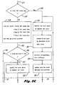
- Figs. 3A and 3B are respectively the upper and lower portions of a schematic flow chart depicting the data processing methodology and structure used for controlling the operation of the error diffusion and pixel assignment gray scaling stage in Fig. 1.
- Figs. 3C and 3D are enlargements of Fig. 3B which have been made in order to enlarge the size of legend used in Figure 3B.
- Fig. 5A is a schematic view of a print engine of a color laser printer which may be used in practicing the invention.
- FIG. 3A through 3D the data processing system shown in these figures provides a detailed explanation of the operation of the error diffusion and pixel assignment stage 16 in Fig. 1.
- This data processing system is comprised of a number of functional blocks which include therein descriptive legend to aid in the reader's understanding of the invention. These functional blocks are actually individual stages of a computer, and as such are sometimes alternatively referred to as “stages” or “test stages” in the case of performing a yes-no test on a particular piece of data.
- the test stages in this system are indicated by the diamond shaped functional blocks, whereas the other operational stages which perform a specific functional operation on the incoming data are rectangular in shape.
- each of the functional blocks or stages therein will be referred to hereinafter as "steps" in order to generically indicate the functional steps performed on the data being operated on in each of the electronic stages.
- a total drop count is calculated for the black, cyan, magenta and yellow minimum available drop count numbers within the 16 level gray table of Fig. 2, and this drop count minimum is compared at step 28 in Fig. 3B (also shown in Figs. 3C and 3D) to a predetermined maximum allowable drop count, V max , as previously defined.
- FIG. 5B there are shown five super pixels 156, 158, 160, 162, and 164 which correspond to the first five levels of gray scale, or the 0-4 gray scale levels for both monochromatic and color laser printing and using dot-next-to-dot-always (DNDA) formatting.
- This Figure 5B represents the most generic case of the novel method combination claimed herein of dot-next-to-dot (DND) formatting used to produce a variable gray scale image in the field of electrophotography.
- DND dot-next-to-dot
- the maximum dot loading or maximum number of dots allowed per super pixel which is equivalent herein to V max of the previously described ink jet examples, is always equal to the number of subdivided pixels within a super pixel.
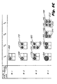
- Figure 5D there is shown an example of variable dot loading in the field of color electrophotography which is equivalent to the variation in ink dye loading in color ink jet technology as previously described.
- Figure 5D includes three rows and four columns of black, cyan, magenta, and yellow super pixels, with the pixel rows indicating large, medium, and small dot sizes for the array of super pixels to be printed in accordance with the example of color dot loadings indicated in the lower portion of Figure 5D.
- the sum of the C, M, Y, and K primary colors is equal to, but does not exceed, the number 4, or the number of subdivided or individual pixels within each of the 2 x 2 super pixels.
Description


Claims (5)
- A method of gray scale electrophotographic printing of dots of one or more colors into a plurality of super pixels in a controlled ordered sequence, wherein a super pixel is a predetermined number of individual pixels greater than one, each pixel being arranged to contain no more than one dot, said method including the steps of using one or more levels of dot loading in each of said superpixels or pixels to achieve one or more values of gray level of a multiple level gray table, and using dot-next-to-dot always (DNDA) formatting, wherein successively printed dots are not printed on top of another in a given pixel area, so that a number of dots printed in each super pixel never exceeds a number of individual or subdivided pixels therein and that there is no planned dot-on-dot color mixing within said super pixels.
- A method according to claim 1 wherein an electrophotographic dot size in each of said pixels is printed for each primary color cyan, magenta, yellow, and black.
- A method according to claim 2 wherein selected large, medium, and small diameter dot sizes controllable by a laser beam of a color electrophotographic printer are used to in turn control the gray level number for each of said primary colors.
- A method according to claim 1 which includes printing a plurality of colors in a single plane within a plurality of super pixels to produce a color image.
- A method according to claim 4 which further includes varying an area of each printed color dot within each super pixel in order to control a gray scale of printed color image.
Applications Claiming Priority (2)
| Application Number | Priority Date | Filing Date | Title |
|---|---|---|---|
| US07/515,946 US5111302A (en) | 1988-12-02 | 1990-04-27 | Method and system for enhancing the quality of both color and black and white images produced by ink jet and electrophotographic printers |
| US515946 | 1990-04-27 |
Publications (3)
| Publication Number | Publication Date |
|---|---|
| EP0454448A2 EP0454448A2 (en) | 1991-10-30 |
| EP0454448A3 EP0454448A3 (en) | 1993-02-24 |
| EP0454448B1 true EP0454448B1 (en) | 1998-09-16 |
Family
ID=24053458
Family Applications (1)
| Application Number | Title | Priority Date | Filing Date |
|---|---|---|---|
| EP91303711A Expired - Lifetime EP0454448B1 (en) | 1990-04-27 | 1991-04-24 | Method and system for enhancing the quality of both color and black and white images produced by electrophotographic printers |
Country Status (5)
| Country | Link |
|---|---|
| US (1) | US5111302A (en) |
| EP (1) | EP0454448B1 (en) |
| JP (1) | JPH05114997A (en) |
| CA (1) | CA2038486C (en) |
| DE (1) | DE69130188T2 (en) |
Families Citing this family (85)
| Publication number | Priority date | Publication date | Assignee | Title |
|---|---|---|---|---|
| EP0499738B1 (en) * | 1991-02-08 | 1996-12-27 | Adobe Systems Inc. | Methods of controlling dot size in digital halftoning with multi-cell threshold arrays |
| US5337167A (en) * | 1991-04-03 | 1994-08-09 | Matsushita Electric Industrial Co., Ltd. | Halftone image forming apparatus including density based dot enlargement |
| US5508727A (en) * | 1991-05-08 | 1996-04-16 | Imagine, Ltd. | Apparatus and method for pattern generation on a dielectric substrate |
| US6043830A (en) * | 1991-05-08 | 2000-03-28 | Cubital, Ltd. | Apparatus for pattern generation on a dielectric substrate |
| US5430469A (en) | 1991-06-05 | 1995-07-04 | Canon Kabushiki Kaisha | Tone recording method using ink recording head |
| US6406114B1 (en) | 1991-06-05 | 2002-06-18 | Canon Kabushiki Kaisha | Tonal product recorded by ink and having a plurality of pixels with plural tonal levels |
| US6036300A (en) | 1992-02-26 | 2000-03-14 | Canon Kabushiki Kaisha | Method for recording image and apparatus therefor and recorded matter by such an apparatus |
| US5314774A (en) * | 1992-05-22 | 1994-05-24 | Hewlett-Packard Company | Method and apparatus for developing color images using dry toners and an intermediate transfer member |
| US5515479A (en) * | 1992-07-23 | 1996-05-07 | Xerox Corporation | Image processing method to reduce marking material coverage in printing processes |
| DE69322914T2 (en) * | 1992-08-17 | 1999-07-29 | Bayer Ag | Raster filter and generating device and method therefor |
| JP3161094B2 (en) * | 1992-10-08 | 2001-04-25 | 富士ゼロックス株式会社 | Recording method in ink jet recording apparatus |
| US5416612A (en) * | 1992-11-06 | 1995-05-16 | Iris Graphics Inc. | Apparatus and method for producing color half-tone images |
| KR960005016B1 (en) * | 1992-11-26 | 1996-04-18 | 삼성전자주식회사 | Printing color control method and circuit in cvp |
| US5434672A (en) * | 1993-06-23 | 1995-07-18 | Hewlett-Packard Company | Pixel error diffusion method |
| US5485183A (en) * | 1993-06-30 | 1996-01-16 | Dataproducts Corporation | Interlaced dot-on-dot printing |
| ATE177996T1 (en) * | 1993-07-30 | 1999-04-15 | Canon Kk | INKJET PRINTING APPARATUS AND INKJET PRINTING METHOD |
| US5914731A (en) * | 1993-09-30 | 1999-06-22 | Canon Kabushiki Kaisha | Data recording using randomized variations to prevent visual artifacts due to non-uniformities in a printing apparatus |
| CA2151093C (en) * | 1994-06-15 | 1998-11-03 | David B. Wallace | Method for producing gradient tonal representations and a printhead for producing the same |
| US5557709A (en) * | 1994-07-01 | 1996-09-17 | Seiko Epson Corporation | Method and apparatus for dither array generation to reduce artifacts in halftoned images |
| US5519787A (en) * | 1994-07-25 | 1996-05-21 | Canon Kabushiki Kaisha | Method of compressing image data having a uniform background tint |
| EP0706891A3 (en) | 1994-10-13 | 1998-05-06 | Imagine Ltd. | Apparatus and methods for non impact imaging and digital printing |
| US5625397A (en) * | 1994-11-23 | 1997-04-29 | Iris Graphics, Inc. | Dot on dot ink jet printing using inks of differing densities |
| US5648801A (en) * | 1994-12-16 | 1997-07-15 | International Business Machines Corporation | Grayscale printing system |
| US5534945A (en) * | 1994-12-16 | 1996-07-09 | International Business Machines Corporation | System and method for providing black diffusion in video image processing |
| US5982990A (en) * | 1995-07-20 | 1999-11-09 | Hewlett-Packard Company | Method and apparatus for converting color space |
| US5739917A (en) * | 1996-07-12 | 1998-04-14 | Seiko Epson Corporation | Error-diffusion-type half-toning employing adaptive thresholding for enhanced smoothness |
| US5838885A (en) * | 1996-09-09 | 1998-11-17 | Seiko Epson Corporation | Salt-and-pepper-noise reduction |
| US5997132A (en) * | 1996-10-22 | 1999-12-07 | Hewlett-Packard Company | Method and apparatus for improving image quality |
| JPH10228365A (en) * | 1997-02-14 | 1998-08-25 | Canon Inc | Printer, print system, and printing method |
| JP3526385B2 (en) * | 1997-03-11 | 2004-05-10 | 株式会社東芝 | Pattern forming equipment |
| US6081340A (en) * | 1997-03-31 | 2000-06-27 | Xerox Corporation | Image processing method to reduce marking material coverage with non-linear specifications |
| JP3530717B2 (en) * | 1997-06-19 | 2004-05-24 | キヤノン株式会社 | Ink jet recording method and apparatus |
| US6089692A (en) * | 1997-08-08 | 2000-07-18 | Eastman Kodak Company | Ink jet printing with multiple drops at pixel locations for gray scale |
| US5966507A (en) * | 1997-08-25 | 1999-10-12 | Hewlett-Packard Company | Image resolution enhancement technology (IRET) for dual dye-load inkjet printer |
| US5912683A (en) * | 1997-08-25 | 1999-06-15 | Lexmark International, Inc. | Method of printing with an ink jet printer using an enhanced horizontal resolution |
| US6135655A (en) * | 1997-10-14 | 2000-10-24 | Hewlett-Packard Company | Multipixel dots in monochrome drop-on-demand printing |
| US6068361A (en) * | 1997-10-30 | 2000-05-30 | Mantell; David A. | Method and apparatus for multiple drop error diffusion in a liquid ink printer |
| JP4018286B2 (en) * | 1998-03-11 | 2007-12-05 | キヤノン株式会社 | Inkjet recording method and apparatus and recording system |
| US6213586B1 (en) * | 1998-04-20 | 2001-04-10 | Hewlett-Packard Company | Method and apparatus for controlling a multicolor inkjet printhead to produce temporally or spatially shingled images |
| US6014227A (en) * | 1998-04-30 | 2000-01-11 | Hewlett-Packard Co. | Printer with progressive column error diffusion system and method of using same for improved printer throughput |
| US6567186B1 (en) * | 1998-10-27 | 2003-05-20 | Hewlett-Packard Company | Method for determining gray values in a printer |
| US6356291B1 (en) * | 1998-11-06 | 2002-03-12 | International Business Machines Corp. | Method and apparatus for providing print quality enhancement |
| US6179407B1 (en) | 1998-11-20 | 2001-01-30 | Hewlett-Packard Company | Multi-pass inkjet printer system and method of using same |
| US6244687B1 (en) | 1999-03-22 | 2001-06-12 | Hewlett-Packard Company | Mixing overprinting and underprinting of inks in an inkjet printer to speed up the dry time of black ink without undesirable hue shifts |
| US6266080B1 (en) * | 1999-04-30 | 2001-07-24 | Creo Srl | Thermal recording with variable power density |
| US20040008381A1 (en) * | 1999-07-16 | 2004-01-15 | Jacob Steve A. | System and method for converting color data to gray data |
| US6604806B1 (en) * | 1999-10-20 | 2003-08-12 | Canon Kabushiki Kaisha | High resolution printing |
| TW452233U (en) * | 2000-04-20 | 2001-08-21 | Cheng Tsung Kan | Housing structure of memory card |
| JP2002029072A (en) * | 2000-07-14 | 2002-01-29 | Canon Inc | Ink jet recording apparatus, its method, and computer readable memory |
| US6982814B1 (en) | 2000-08-23 | 2006-01-03 | Hewlett-Packard Development Company, L.P. | Image printing devices with AM/FM half-toning with self-determination of dot size and method of implementing same |
| JP3969981B2 (en) * | 2000-09-22 | 2007-09-05 | キヤノン株式会社 | Electron source driving method, driving circuit, electron source, and image forming apparatus |
| US6870645B1 (en) | 2000-10-03 | 2005-03-22 | Hewlett-Packard Development Company, L.P. | Plane dependent matrix based halftoning |
| JP3969985B2 (en) | 2000-10-04 | 2007-09-05 | キヤノン株式会社 | Electron source, image forming apparatus driving method, and image forming apparatus |
| US7292369B2 (en) * | 2000-12-28 | 2007-11-06 | Seiko Epson Corporation | Logo data generating method and system |
| US6847377B2 (en) * | 2001-01-05 | 2005-01-25 | Seiko Epson Corporation | System, method and computer program converting pixels to luminance levels and assigning colors associated with luminance levels in printer or display output devices |
| EP1257113A3 (en) * | 2001-05-11 | 2006-04-12 | Seiko Epson Corporation | Printing with multiple pixels as a unit of gradation reproduction |
| US6967753B2 (en) * | 2001-07-31 | 2005-11-22 | Hewlett-Packard Development Company, L.P. | Plane dependent compression |
| US7355747B2 (en) * | 2002-01-18 | 2008-04-08 | Hewlett-Packard Development Company, L.P. | System for improving the speed of data processing |
| US20030179410A1 (en) * | 2002-03-21 | 2003-09-25 | Velde Koen Van De | Multilevel colour error-diffusion providing reduced sensitivity to printing process variability errors |
| US20040085590A1 (en) * | 2002-10-31 | 2004-05-06 | Kurt Thiessen | Modifying an image based on image quality |
| US20040130753A1 (en) * | 2003-01-06 | 2004-07-08 | Crounse Kenneth R. | Halftone method and system using hybrid AM/FM screening for highlight/shadow tonal regions |
| US7450270B2 (en) * | 2004-01-16 | 2008-11-11 | Hewlett-Packard Development Company, L.P. | Image data processing methods, hard imaging devices, and articles of manufacture |
| JP2006007520A (en) * | 2004-06-24 | 2006-01-12 | Rohm Co Ltd | Organic el printer |
| GB0711341D0 (en) * | 2007-06-12 | 2007-07-25 | Ffei Ltd | Multilevel screening |
| US8401416B2 (en) | 2010-11-09 | 2013-03-19 | Eastman Kodak Company | Electrophotographically printing job having job type |
| US8639053B2 (en) * | 2011-01-18 | 2014-01-28 | Dimension, Inc. | Methods and systems for up-scaling a standard definition (SD) video to high definition (HD) quality |
| JP5310754B2 (en) * | 2011-01-31 | 2013-10-09 | ブラザー工業株式会社 | Droplet discharge apparatus and program thereof |
| JP6036632B2 (en) * | 2013-10-04 | 2016-11-30 | カシオ計算機株式会社 | Printing plate manufacturing method, printing plate manufacturing apparatus, data generation method, and program |
| US11007791B2 (en) * | 2014-11-19 | 2021-05-18 | Electronics For Imaging, Ing. | Multi-layered textured printing |
| US11169463B2 (en) | 2017-08-25 | 2021-11-09 | Hp Indigo B.V. | Adjusting power levels to compensate for print spot size variation |
| US10723133B2 (en) | 2018-10-04 | 2020-07-28 | Ricoh Company, Ltd. | Ink estimation mechanism |
| US10643115B1 (en) | 2019-06-28 | 2020-05-05 | Ricoh Company, Ltd. | Ink estimation adjustment mechanism |
| US10990863B1 (en) | 2020-02-28 | 2021-04-27 | Ricoh Company, Ltd. | Direct deposit ink estimation mechanism |
| US11155099B2 (en) | 2020-02-28 | 2021-10-26 | Ricoh Company, Ltd. | Printer density control mechanism |
| US11247454B2 (en) | 2020-02-28 | 2022-02-15 | Ricoh Company, Ltd. | Uncalibrated ink deposition generation mechanism |
| US10902304B1 (en) | 2020-02-28 | 2021-01-26 | Ricoh Company, Ltd. | Optical density monitoring mechanism |
| US11182113B2 (en) | 2020-02-28 | 2021-11-23 | Ricoh Company, Ltd. | Ink deposition monitoring mechanism |
| US11283936B1 (en) | 2020-12-18 | 2022-03-22 | Ricoh Company, Ltd. | Ink usage estimation for each drop size based on histogram and calibrated drop fraction |
| US11738552B2 (en) | 2021-02-02 | 2023-08-29 | Ricoh Company, Ltd. | Ink model generation mechanism |
| US11475260B2 (en) | 2021-02-02 | 2022-10-18 | Ricoh Company, Ltd. | Ink model generation mechanism |
| US11570332B2 (en) | 2021-02-25 | 2023-01-31 | Ricoh Company, Ltd. | Color space ink model generation mechanism |
| US11745501B1 (en) | 2022-02-11 | 2023-09-05 | Ricoh Company, Ltd. | Drop size monitoring mechanism |
| US11755865B1 (en) | 2022-03-01 | 2023-09-12 | Ricoh Company, Ltd. | Drop size monitoring mechanism |
| US11675991B1 (en) | 2022-03-04 | 2023-06-13 | Ricoh Company, Ltd. | Color space ink model generation mechanism |
| US11731420B1 (en) | 2022-03-14 | 2023-08-22 | Ricoh Company, Ltd. | Drop size monitoring mechanism |
Family Cites Families (10)
| Publication number | Priority date | Publication date | Assignee | Title |
|---|---|---|---|---|
| FR2497043B1 (en) * | 1980-12-19 | 1985-09-13 | Cit Alcatel | IMAGE PRINTING DEVICE |
| JPS5968245A (en) * | 1982-10-13 | 1984-04-18 | Ricoh Co Ltd | Multi-color ink jet recording method |
| US4672432A (en) * | 1983-04-28 | 1987-06-09 | Canon Kabushiki Kaisha | Method for recording a color image using dots of colorants of different densities |
| JPS6085675A (en) * | 1983-10-17 | 1985-05-15 | Fuji Xerox Co Ltd | Color copying machine |
| US4746935A (en) * | 1985-11-22 | 1988-05-24 | Hewlett-Packard Company | Multitone ink jet printer and method of operation |
| JP2621856B2 (en) * | 1986-06-06 | 1997-06-18 | 株式会社リコー | Digital color image reproduction processing method and apparatus |
| US4680645A (en) * | 1986-08-25 | 1987-07-14 | Hewlett-Packard Company | Method for rendering gray scale images with variable dot sizes |
| US4965672A (en) * | 1987-05-11 | 1990-10-23 | The Mead Corporation | Method and apparatus for halftone imaging |
| US4930018A (en) * | 1988-12-02 | 1990-05-29 | Hewlett-Packard Company | Method and system for enhancing the quality of both color and black and white images produced by ink jet printers |
| US5012257A (en) * | 1990-03-16 | 1991-04-30 | Hewlett-Packard Company | Ink jet color graphics printing |
-
1990
- 1990-04-27 US US07/515,946 patent/US5111302A/en not_active Expired - Lifetime
-
1991
- 1991-03-18 CA CA002038486A patent/CA2038486C/en not_active Expired - Fee Related
- 1991-04-24 EP EP91303711A patent/EP0454448B1/en not_active Expired - Lifetime
- 1991-04-24 DE DE69130188T patent/DE69130188T2/en not_active Expired - Fee Related
- 1991-04-30 JP JP3126670A patent/JPH05114997A/en active Pending
Also Published As
| Publication number | Publication date |
|---|---|
| DE69130188T2 (en) | 1999-02-25 |
| US5111302A (en) | 1992-05-05 |
| EP0454448A2 (en) | 1991-10-30 |
| JPH05114997A (en) | 1993-05-07 |
| EP0454448A3 (en) | 1993-02-24 |
| CA2038486C (en) | 1995-02-07 |
| DE69130188D1 (en) | 1998-10-22 |
Similar Documents
| Publication | Publication Date | Title |
|---|---|---|
| EP0454448B1 (en) | Method and system for enhancing the quality of both color and black and white images produced by electrophotographic printers | |
| JP2980331B2 (en) | Method and system for improving color and black and white images by ink jet printer | |
| EP1743477B1 (en) | Multi-color printing using a halftone screen | |
| US4595948A (en) | Multicolor ink jet recording apparatus having means for preventing blurring of ink | |
| US4974067A (en) | Multi-step-digital color image reproducing method and apparatus | |
| EP0444290B1 (en) | Method and system for reproducing monochromatic and color images using ordered dither and error diffusion | |
| EP0633688B1 (en) | Image forming apparatus and method | |
| US5642439A (en) | Digital image processing method suitable for halftone representation based on dither process | |
| WO2005112431A1 (en) | Hybrid dot-line halftone composite screens | |
| US7355747B2 (en) | System for improving the speed of data processing | |
| EP1033257B1 (en) | Compensation for print-direction induced hue shift using depletion of pixels | |
| US6344870B1 (en) | Methods of providing lower resolution format data into higher resolution format | |
| GB2139449A (en) | Colour Image Processor | |
| US7158262B2 (en) | Multi-level error diffusion apparatus and method of using same | |
| EP0954164B1 (en) | Printer with progressive column error diffusion system and method of using the same for improved printer throughput | |
| US5633990A (en) | Method of non-overlapping color printing | |
| EP1241868B1 (en) | Image processing apparatus | |
| US5899604A (en) | Extending the dynamic range of single-bit, electrographic printers through multi-pass printing | |
| JP3733983B2 (en) | Image forming apparatus | |
| EP0369779B1 (en) | Image memory apparatus | |
| JP3431687B2 (en) | Image forming apparatus and image forming system | |
| JPS60106270A (en) | Color ink jet printer | |
| JPH06106734A (en) | Method and device for printing | |
| JPH0818782A (en) | Method and device for recording polychromatic information | |
| JPH05221031A (en) | Image forming apparatus |
Legal Events
| Date | Code | Title | Description |
|---|---|---|---|
| PUAI | Public reference made under article 153(3) epc to a published international application that has entered the european phase |
Free format text: ORIGINAL CODE: 0009012 |
|
| AK | Designated contracting states |
Kind code of ref document: A2 Designated state(s): DE FR GB IT |
|
| PUAL | Search report despatched |
Free format text: ORIGINAL CODE: 0009013 |
|
| AK | Designated contracting states |
Kind code of ref document: A3 Designated state(s): DE FR GB IT |
|
| 17P | Request for examination filed |
Effective date: 19930802 |
|
| 17Q | First examination report despatched |
Effective date: 19950530 |
|
| GRAG | Despatch of communication of intention to grant |
Free format text: ORIGINAL CODE: EPIDOS AGRA |
|
| GRAG | Despatch of communication of intention to grant |
Free format text: ORIGINAL CODE: EPIDOS AGRA |
|
| GRAH | Despatch of communication of intention to grant a patent |
Free format text: ORIGINAL CODE: EPIDOS IGRA |
|
| GRAH | Despatch of communication of intention to grant a patent |
Free format text: ORIGINAL CODE: EPIDOS IGRA |
|
| GRAA | (expected) grant |
Free format text: ORIGINAL CODE: 0009210 |
|
| AK | Designated contracting states |
Kind code of ref document: B1 Designated state(s): DE FR GB IT |
|
| REF | Corresponds to: |
Ref document number: 69130188 Country of ref document: DE Date of ref document: 19981022 |
|
| ET | Fr: translation filed | ||
| PLBE | No opposition filed within time limit |
Free format text: ORIGINAL CODE: 0009261 |
|
| STAA | Information on the status of an ep patent application or granted ep patent |
Free format text: STATUS: NO OPPOSITION FILED WITHIN TIME LIMIT |
|
| 26N | No opposition filed | ||
| REG | Reference to a national code |
Ref country code: GB Ref legal event code: 732E |
|
| REG | Reference to a national code |
Ref country code: FR Ref legal event code: TP |
|
| REG | Reference to a national code |
Ref country code: GB Ref legal event code: IF02 |
|
| PGFP | Annual fee paid to national office [announced via postgrant information from national office to epo] |
Ref country code: IT Payment date: 20060430 Year of fee payment: 16 |
|
| PGFP | Annual fee paid to national office [announced via postgrant information from national office to epo] |
Ref country code: DE Payment date: 20070531 Year of fee payment: 17 |
|
| PGFP | Annual fee paid to national office [announced via postgrant information from national office to epo] |
Ref country code: GB Payment date: 20070425 Year of fee payment: 17 |
|
| PGFP | Annual fee paid to national office [announced via postgrant information from national office to epo] |
Ref country code: FR Payment date: 20070417 Year of fee payment: 17 |
|
| GBPC | Gb: european patent ceased through non-payment of renewal fee |
Effective date: 20080424 |
|
| PG25 | Lapsed in a contracting state [announced via postgrant information from national office to epo] |
Ref country code: DE Free format text: LAPSE BECAUSE OF NON-PAYMENT OF DUE FEES Effective date: 20081101 |
|
| REG | Reference to a national code |
Ref country code: FR Ref legal event code: ST Effective date: 20081231 |
|
| PG25 | Lapsed in a contracting state [announced via postgrant information from national office to epo] |
Ref country code: FR Free format text: LAPSE BECAUSE OF NON-PAYMENT OF DUE FEES Effective date: 20080430 |
|
| PG25 | Lapsed in a contracting state [announced via postgrant information from national office to epo] |
Ref country code: GB Free format text: LAPSE BECAUSE OF NON-PAYMENT OF DUE FEES Effective date: 20080424 |
|
| PG25 | Lapsed in a contracting state [announced via postgrant information from national office to epo] |
Ref country code: IT Free format text: LAPSE BECAUSE OF NON-PAYMENT OF DUE FEES Effective date: 20070424 |