EP0454645A1 - Artificial joint mechanism - Google Patents
Artificial joint mechanism Download PDFInfo
- Publication number
- EP0454645A1 EP0454645A1 EP91850102A EP91850102A EP0454645A1 EP 0454645 A1 EP0454645 A1 EP 0454645A1 EP 91850102 A EP91850102 A EP 91850102A EP 91850102 A EP91850102 A EP 91850102A EP 0454645 A1 EP0454645 A1 EP 0454645A1
- Authority
- EP
- European Patent Office
- Prior art keywords
- section
- joint mechanism
- mid
- artificial joint
- reinforcement
- Prior art date
- Legal status (The legal status is an assumption and is not a legal conclusion. Google has not performed a legal analysis and makes no representation as to the accuracy of the status listed.)
- Granted
Links
Images


Classifications
-
- A—HUMAN NECESSITIES
- A61—MEDICAL OR VETERINARY SCIENCE; HYGIENE
- A61L—METHODS OR APPARATUS FOR STERILISING MATERIALS OR OBJECTS IN GENERAL; DISINFECTION, STERILISATION OR DEODORISATION OF AIR; CHEMICAL ASPECTS OF BANDAGES, DRESSINGS, ABSORBENT PADS OR SURGICAL ARTICLES; MATERIALS FOR BANDAGES, DRESSINGS, ABSORBENT PADS OR SURGICAL ARTICLES
- A61L27/00—Materials for grafts or prostheses or for coating grafts or prostheses
- A61L27/02—Inorganic materials
- A61L27/04—Metals or alloys
- A61L27/06—Titanium or titanium alloys
-
- A—HUMAN NECESSITIES
- A61—MEDICAL OR VETERINARY SCIENCE; HYGIENE
- A61F—FILTERS IMPLANTABLE INTO BLOOD VESSELS; PROSTHESES; DEVICES PROVIDING PATENCY TO, OR PREVENTING COLLAPSING OF, TUBULAR STRUCTURES OF THE BODY, e.g. STENTS; ORTHOPAEDIC, NURSING OR CONTRACEPTIVE DEVICES; FOMENTATION; TREATMENT OR PROTECTION OF EYES OR EARS; BANDAGES, DRESSINGS OR ABSORBENT PADS; FIRST-AID KITS
- A61F2/00—Filters implantable into blood vessels; Prostheses, i.e. artificial substitutes or replacements for parts of the body; Appliances for connecting them with the body; Devices providing patency to, or preventing collapsing of, tubular structures of the body, e.g. stents
- A61F2/02—Prostheses implantable into the body
- A61F2/30—Joints
- A61F2/3094—Designing or manufacturing processes
- A61F2/30965—Reinforcing the prosthesis by embedding particles or fibres during moulding or dipping
-
- A—HUMAN NECESSITIES
- A61—MEDICAL OR VETERINARY SCIENCE; HYGIENE
- A61F—FILTERS IMPLANTABLE INTO BLOOD VESSELS; PROSTHESES; DEVICES PROVIDING PATENCY TO, OR PREVENTING COLLAPSING OF, TUBULAR STRUCTURES OF THE BODY, e.g. STENTS; ORTHOPAEDIC, NURSING OR CONTRACEPTIVE DEVICES; FOMENTATION; TREATMENT OR PROTECTION OF EYES OR EARS; BANDAGES, DRESSINGS OR ABSORBENT PADS; FIRST-AID KITS
- A61F2/00—Filters implantable into blood vessels; Prostheses, i.e. artificial substitutes or replacements for parts of the body; Appliances for connecting them with the body; Devices providing patency to, or preventing collapsing of, tubular structures of the body, e.g. stents
- A61F2/02—Prostheses implantable into the body
- A61F2/30—Joints
- A61F2/42—Joints for wrists or ankles; for hands, e.g. fingers; for feet, e.g. toes
-
- A—HUMAN NECESSITIES
- A61—MEDICAL OR VETERINARY SCIENCE; HYGIENE
- A61L—METHODS OR APPARATUS FOR STERILISING MATERIALS OR OBJECTS IN GENERAL; DISINFECTION, STERILISATION OR DEODORISATION OF AIR; CHEMICAL ASPECTS OF BANDAGES, DRESSINGS, ABSORBENT PADS OR SURGICAL ARTICLES; MATERIALS FOR BANDAGES, DRESSINGS, ABSORBENT PADS OR SURGICAL ARTICLES
- A61L27/00—Materials for grafts or prostheses or for coating grafts or prostheses
- A61L27/14—Macromolecular materials
- A61L27/18—Macromolecular materials obtained otherwise than by reactions only involving carbon-to-carbon unsaturated bonds
-
- A—HUMAN NECESSITIES
- A61—MEDICAL OR VETERINARY SCIENCE; HYGIENE
- A61F—FILTERS IMPLANTABLE INTO BLOOD VESSELS; PROSTHESES; DEVICES PROVIDING PATENCY TO, OR PREVENTING COLLAPSING OF, TUBULAR STRUCTURES OF THE BODY, e.g. STENTS; ORTHOPAEDIC, NURSING OR CONTRACEPTIVE DEVICES; FOMENTATION; TREATMENT OR PROTECTION OF EYES OR EARS; BANDAGES, DRESSINGS OR ABSORBENT PADS; FIRST-AID KITS
- A61F2/00—Filters implantable into blood vessels; Prostheses, i.e. artificial substitutes or replacements for parts of the body; Appliances for connecting them with the body; Devices providing patency to, or preventing collapsing of, tubular structures of the body, e.g. stents
- A61F2/02—Prostheses implantable into the body
- A61F2/30—Joints
- A61F2/32—Joints for the hip
-
- A—HUMAN NECESSITIES
- A61—MEDICAL OR VETERINARY SCIENCE; HYGIENE
- A61F—FILTERS IMPLANTABLE INTO BLOOD VESSELS; PROSTHESES; DEVICES PROVIDING PATENCY TO, OR PREVENTING COLLAPSING OF, TUBULAR STRUCTURES OF THE BODY, e.g. STENTS; ORTHOPAEDIC, NURSING OR CONTRACEPTIVE DEVICES; FOMENTATION; TREATMENT OR PROTECTION OF EYES OR EARS; BANDAGES, DRESSINGS OR ABSORBENT PADS; FIRST-AID KITS
- A61F2/00—Filters implantable into blood vessels; Prostheses, i.e. artificial substitutes or replacements for parts of the body; Appliances for connecting them with the body; Devices providing patency to, or preventing collapsing of, tubular structures of the body, e.g. stents
- A61F2/02—Prostheses implantable into the body
- A61F2/30—Joints
- A61F2/38—Joints for elbows or knees
- A61F2/3804—Joints for elbows or knees for elbows
-
- A—HUMAN NECESSITIES
- A61—MEDICAL OR VETERINARY SCIENCE; HYGIENE
- A61F—FILTERS IMPLANTABLE INTO BLOOD VESSELS; PROSTHESES; DEVICES PROVIDING PATENCY TO, OR PREVENTING COLLAPSING OF, TUBULAR STRUCTURES OF THE BODY, e.g. STENTS; ORTHOPAEDIC, NURSING OR CONTRACEPTIVE DEVICES; FOMENTATION; TREATMENT OR PROTECTION OF EYES OR EARS; BANDAGES, DRESSINGS OR ABSORBENT PADS; FIRST-AID KITS
- A61F2/00—Filters implantable into blood vessels; Prostheses, i.e. artificial substitutes or replacements for parts of the body; Appliances for connecting them with the body; Devices providing patency to, or preventing collapsing of, tubular structures of the body, e.g. stents
- A61F2/02—Prostheses implantable into the body
- A61F2/30—Joints
- A61F2/42—Joints for wrists or ankles; for hands, e.g. fingers; for feet, e.g. toes
- A61F2/4202—Joints for wrists or ankles; for hands, e.g. fingers; for feet, e.g. toes for ankles
-
- A—HUMAN NECESSITIES
- A61—MEDICAL OR VETERINARY SCIENCE; HYGIENE
- A61F—FILTERS IMPLANTABLE INTO BLOOD VESSELS; PROSTHESES; DEVICES PROVIDING PATENCY TO, OR PREVENTING COLLAPSING OF, TUBULAR STRUCTURES OF THE BODY, e.g. STENTS; ORTHOPAEDIC, NURSING OR CONTRACEPTIVE DEVICES; FOMENTATION; TREATMENT OR PROTECTION OF EYES OR EARS; BANDAGES, DRESSINGS OR ABSORBENT PADS; FIRST-AID KITS
- A61F2/00—Filters implantable into blood vessels; Prostheses, i.e. artificial substitutes or replacements for parts of the body; Appliances for connecting them with the body; Devices providing patency to, or preventing collapsing of, tubular structures of the body, e.g. stents
- A61F2/02—Prostheses implantable into the body
- A61F2/30—Joints
- A61F2/42—Joints for wrists or ankles; for hands, e.g. fingers; for feet, e.g. toes
- A61F2/4225—Joints for wrists or ankles; for hands, e.g. fingers; for feet, e.g. toes for feet, e.g. toes
-
- A—HUMAN NECESSITIES
- A61—MEDICAL OR VETERINARY SCIENCE; HYGIENE
- A61F—FILTERS IMPLANTABLE INTO BLOOD VESSELS; PROSTHESES; DEVICES PROVIDING PATENCY TO, OR PREVENTING COLLAPSING OF, TUBULAR STRUCTURES OF THE BODY, e.g. STENTS; ORTHOPAEDIC, NURSING OR CONTRACEPTIVE DEVICES; FOMENTATION; TREATMENT OR PROTECTION OF EYES OR EARS; BANDAGES, DRESSINGS OR ABSORBENT PADS; FIRST-AID KITS
- A61F2/00—Filters implantable into blood vessels; Prostheses, i.e. artificial substitutes or replacements for parts of the body; Appliances for connecting them with the body; Devices providing patency to, or preventing collapsing of, tubular structures of the body, e.g. stents
- A61F2/02—Prostheses implantable into the body
- A61F2/30—Joints
- A61F2/42—Joints for wrists or ankles; for hands, e.g. fingers; for feet, e.g. toes
- A61F2/4241—Joints for wrists or ankles; for hands, e.g. fingers; for feet, e.g. toes for hands, e.g. fingers
-
- A—HUMAN NECESSITIES
- A61—MEDICAL OR VETERINARY SCIENCE; HYGIENE
- A61F—FILTERS IMPLANTABLE INTO BLOOD VESSELS; PROSTHESES; DEVICES PROVIDING PATENCY TO, OR PREVENTING COLLAPSING OF, TUBULAR STRUCTURES OF THE BODY, e.g. STENTS; ORTHOPAEDIC, NURSING OR CONTRACEPTIVE DEVICES; FOMENTATION; TREATMENT OR PROTECTION OF EYES OR EARS; BANDAGES, DRESSINGS OR ABSORBENT PADS; FIRST-AID KITS
- A61F2/00—Filters implantable into blood vessels; Prostheses, i.e. artificial substitutes or replacements for parts of the body; Appliances for connecting them with the body; Devices providing patency to, or preventing collapsing of, tubular structures of the body, e.g. stents
- A61F2/02—Prostheses implantable into the body
- A61F2/30—Joints
- A61F2/42—Joints for wrists or ankles; for hands, e.g. fingers; for feet, e.g. toes
- A61F2/4261—Joints for wrists or ankles; for hands, e.g. fingers; for feet, e.g. toes for wrists
-
- A—HUMAN NECESSITIES
- A61—MEDICAL OR VETERINARY SCIENCE; HYGIENE
- A61F—FILTERS IMPLANTABLE INTO BLOOD VESSELS; PROSTHESES; DEVICES PROVIDING PATENCY TO, OR PREVENTING COLLAPSING OF, TUBULAR STRUCTURES OF THE BODY, e.g. STENTS; ORTHOPAEDIC, NURSING OR CONTRACEPTIVE DEVICES; FOMENTATION; TREATMENT OR PROTECTION OF EYES OR EARS; BANDAGES, DRESSINGS OR ABSORBENT PADS; FIRST-AID KITS
- A61F2/00—Filters implantable into blood vessels; Prostheses, i.e. artificial substitutes or replacements for parts of the body; Appliances for connecting them with the body; Devices providing patency to, or preventing collapsing of, tubular structures of the body, e.g. stents
- A61F2/02—Prostheses implantable into the body
- A61F2/30—Joints
- A61F2002/30001—Additional features of subject-matter classified in A61F2/28, A61F2/30 and subgroups thereof
- A61F2002/30108—Shapes
- A61F2002/30199—Three-dimensional shapes
- A61F2002/30289—Three-dimensional shapes helically-coiled
-
- A—HUMAN NECESSITIES
- A61—MEDICAL OR VETERINARY SCIENCE; HYGIENE
- A61F—FILTERS IMPLANTABLE INTO BLOOD VESSELS; PROSTHESES; DEVICES PROVIDING PATENCY TO, OR PREVENTING COLLAPSING OF, TUBULAR STRUCTURES OF THE BODY, e.g. STENTS; ORTHOPAEDIC, NURSING OR CONTRACEPTIVE DEVICES; FOMENTATION; TREATMENT OR PROTECTION OF EYES OR EARS; BANDAGES, DRESSINGS OR ABSORBENT PADS; FIRST-AID KITS
- A61F2/00—Filters implantable into blood vessels; Prostheses, i.e. artificial substitutes or replacements for parts of the body; Appliances for connecting them with the body; Devices providing patency to, or preventing collapsing of, tubular structures of the body, e.g. stents
- A61F2/02—Prostheses implantable into the body
- A61F2/30—Joints
- A61F2002/30001—Additional features of subject-matter classified in A61F2/28, A61F2/30 and subgroups thereof
- A61F2002/30108—Shapes
- A61F2002/30199—Three-dimensional shapes
- A61F2002/30291—Three-dimensional shapes spirally-coiled, i.e. having a 2D spiral cross-section
-
- A—HUMAN NECESSITIES
- A61—MEDICAL OR VETERINARY SCIENCE; HYGIENE
- A61F—FILTERS IMPLANTABLE INTO BLOOD VESSELS; PROSTHESES; DEVICES PROVIDING PATENCY TO, OR PREVENTING COLLAPSING OF, TUBULAR STRUCTURES OF THE BODY, e.g. STENTS; ORTHOPAEDIC, NURSING OR CONTRACEPTIVE DEVICES; FOMENTATION; TREATMENT OR PROTECTION OF EYES OR EARS; BANDAGES, DRESSINGS OR ABSORBENT PADS; FIRST-AID KITS
- A61F2/00—Filters implantable into blood vessels; Prostheses, i.e. artificial substitutes or replacements for parts of the body; Appliances for connecting them with the body; Devices providing patency to, or preventing collapsing of, tubular structures of the body, e.g. stents
- A61F2/02—Prostheses implantable into the body
- A61F2/30—Joints
- A61F2002/30001—Additional features of subject-matter classified in A61F2/28, A61F2/30 and subgroups thereof
- A61F2002/30316—The prosthesis having different structural features at different locations within the same prosthesis; Connections between prosthetic parts; Special structural features of bone or joint prostheses not otherwise provided for
- A61F2002/30535—Special structural features of bone or joint prostheses not otherwise provided for
- A61F2002/30563—Special structural features of bone or joint prostheses not otherwise provided for having elastic means or damping means, different from springs, e.g. including an elastomeric core or shock absorbers
-
- A—HUMAN NECESSITIES
- A61—MEDICAL OR VETERINARY SCIENCE; HYGIENE
- A61F—FILTERS IMPLANTABLE INTO BLOOD VESSELS; PROSTHESES; DEVICES PROVIDING PATENCY TO, OR PREVENTING COLLAPSING OF, TUBULAR STRUCTURES OF THE BODY, e.g. STENTS; ORTHOPAEDIC, NURSING OR CONTRACEPTIVE DEVICES; FOMENTATION; TREATMENT OR PROTECTION OF EYES OR EARS; BANDAGES, DRESSINGS OR ABSORBENT PADS; FIRST-AID KITS
- A61F2/00—Filters implantable into blood vessels; Prostheses, i.e. artificial substitutes or replacements for parts of the body; Appliances for connecting them with the body; Devices providing patency to, or preventing collapsing of, tubular structures of the body, e.g. stents
- A61F2/02—Prostheses implantable into the body
- A61F2/30—Joints
- A61F2002/30001—Additional features of subject-matter classified in A61F2/28, A61F2/30 and subgroups thereof
- A61F2002/30316—The prosthesis having different structural features at different locations within the same prosthesis; Connections between prosthetic parts; Special structural features of bone or joint prostheses not otherwise provided for
- A61F2002/30535—Special structural features of bone or joint prostheses not otherwise provided for
- A61F2002/30565—Special structural features of bone or joint prostheses not otherwise provided for having spring elements
- A61F2002/30566—Helical springs
-
- A—HUMAN NECESSITIES
- A61—MEDICAL OR VETERINARY SCIENCE; HYGIENE
- A61F—FILTERS IMPLANTABLE INTO BLOOD VESSELS; PROSTHESES; DEVICES PROVIDING PATENCY TO, OR PREVENTING COLLAPSING OF, TUBULAR STRUCTURES OF THE BODY, e.g. STENTS; ORTHOPAEDIC, NURSING OR CONTRACEPTIVE DEVICES; FOMENTATION; TREATMENT OR PROTECTION OF EYES OR EARS; BANDAGES, DRESSINGS OR ABSORBENT PADS; FIRST-AID KITS
- A61F2/00—Filters implantable into blood vessels; Prostheses, i.e. artificial substitutes or replacements for parts of the body; Appliances for connecting them with the body; Devices providing patency to, or preventing collapsing of, tubular structures of the body, e.g. stents
- A61F2/02—Prostheses implantable into the body
- A61F2/30—Joints
- A61F2002/30001—Additional features of subject-matter classified in A61F2/28, A61F2/30 and subgroups thereof
- A61F2002/30316—The prosthesis having different structural features at different locations within the same prosthesis; Connections between prosthetic parts; Special structural features of bone or joint prostheses not otherwise provided for
- A61F2002/30535—Special structural features of bone or joint prostheses not otherwise provided for
- A61F2002/30565—Special structural features of bone or joint prostheses not otherwise provided for having spring elements
- A61F2002/30573—2-D spiral springs
-
- A—HUMAN NECESSITIES
- A61—MEDICAL OR VETERINARY SCIENCE; HYGIENE
- A61F—FILTERS IMPLANTABLE INTO BLOOD VESSELS; PROSTHESES; DEVICES PROVIDING PATENCY TO, OR PREVENTING COLLAPSING OF, TUBULAR STRUCTURES OF THE BODY, e.g. STENTS; ORTHOPAEDIC, NURSING OR CONTRACEPTIVE DEVICES; FOMENTATION; TREATMENT OR PROTECTION OF EYES OR EARS; BANDAGES, DRESSINGS OR ABSORBENT PADS; FIRST-AID KITS
- A61F2/00—Filters implantable into blood vessels; Prostheses, i.e. artificial substitutes or replacements for parts of the body; Appliances for connecting them with the body; Devices providing patency to, or preventing collapsing of, tubular structures of the body, e.g. stents
- A61F2/02—Prostheses implantable into the body
- A61F2/30—Joints
- A61F2/30767—Special external or bone-contacting surface, e.g. coating for improving bone ingrowth
- A61F2/30771—Special external or bone-contacting surface, e.g. coating for improving bone ingrowth applied in original prostheses, e.g. holes or grooves
- A61F2002/30878—Special external or bone-contacting surface, e.g. coating for improving bone ingrowth applied in original prostheses, e.g. holes or grooves with non-sharp protrusions, for instance contacting the bone for anchoring, e.g. keels, pegs, pins, posts, shanks, stems, struts
-
- A—HUMAN NECESSITIES
- A61—MEDICAL OR VETERINARY SCIENCE; HYGIENE
- A61F—FILTERS IMPLANTABLE INTO BLOOD VESSELS; PROSTHESES; DEVICES PROVIDING PATENCY TO, OR PREVENTING COLLAPSING OF, TUBULAR STRUCTURES OF THE BODY, e.g. STENTS; ORTHOPAEDIC, NURSING OR CONTRACEPTIVE DEVICES; FOMENTATION; TREATMENT OR PROTECTION OF EYES OR EARS; BANDAGES, DRESSINGS OR ABSORBENT PADS; FIRST-AID KITS
- A61F2/00—Filters implantable into blood vessels; Prostheses, i.e. artificial substitutes or replacements for parts of the body; Appliances for connecting them with the body; Devices providing patency to, or preventing collapsing of, tubular structures of the body, e.g. stents
- A61F2/02—Prostheses implantable into the body
- A61F2/30—Joints
- A61F2/30767—Special external or bone-contacting surface, e.g. coating for improving bone ingrowth
- A61F2/30907—Nets or sleeves applied to surface of prostheses or in cement
- A61F2002/30919—Sleeves
-
- A—HUMAN NECESSITIES
- A61—MEDICAL OR VETERINARY SCIENCE; HYGIENE
- A61F—FILTERS IMPLANTABLE INTO BLOOD VESSELS; PROSTHESES; DEVICES PROVIDING PATENCY TO, OR PREVENTING COLLAPSING OF, TUBULAR STRUCTURES OF THE BODY, e.g. STENTS; ORTHOPAEDIC, NURSING OR CONTRACEPTIVE DEVICES; FOMENTATION; TREATMENT OR PROTECTION OF EYES OR EARS; BANDAGES, DRESSINGS OR ABSORBENT PADS; FIRST-AID KITS
- A61F2230/00—Geometry of prostheses classified in groups A61F2/00 - A61F2/26 or A61F2/82 or A61F9/00 or A61F11/00 or subgroups thereof
- A61F2230/0063—Three-dimensional shapes
- A61F2230/0091—Three-dimensional shapes helically-coiled or spirally-coiled, i.e. having a 2-D spiral cross-section
-
- A—HUMAN NECESSITIES
- A61—MEDICAL OR VETERINARY SCIENCE; HYGIENE
- A61F—FILTERS IMPLANTABLE INTO BLOOD VESSELS; PROSTHESES; DEVICES PROVIDING PATENCY TO, OR PREVENTING COLLAPSING OF, TUBULAR STRUCTURES OF THE BODY, e.g. STENTS; ORTHOPAEDIC, NURSING OR CONTRACEPTIVE DEVICES; FOMENTATION; TREATMENT OR PROTECTION OF EYES OR EARS; BANDAGES, DRESSINGS OR ABSORBENT PADS; FIRST-AID KITS
- A61F2310/00—Prostheses classified in A61F2/28 or A61F2/30 - A61F2/44 being constructed from or coated with a particular material
- A61F2310/00005—The prosthesis being constructed from a particular material
- A61F2310/00011—Metals or alloys
- A61F2310/00023—Titanium or titanium-based alloys, e.g. Ti-Ni alloys
-
- A—HUMAN NECESSITIES
- A61—MEDICAL OR VETERINARY SCIENCE; HYGIENE
- A61F—FILTERS IMPLANTABLE INTO BLOOD VESSELS; PROSTHESES; DEVICES PROVIDING PATENCY TO, OR PREVENTING COLLAPSING OF, TUBULAR STRUCTURES OF THE BODY, e.g. STENTS; ORTHOPAEDIC, NURSING OR CONTRACEPTIVE DEVICES; FOMENTATION; TREATMENT OR PROTECTION OF EYES OR EARS; BANDAGES, DRESSINGS OR ABSORBENT PADS; FIRST-AID KITS
- A61F2310/00—Prostheses classified in A61F2/28 or A61F2/30 - A61F2/44 being constructed from or coated with a particular material
- A61F2310/00389—The prosthesis being coated or covered with a particular material
- A61F2310/00395—Coating or prosthesis-covering structure made of metals or of alloys
- A61F2310/00407—Coating made of titanium or of Ti-based alloys
-
- A—HUMAN NECESSITIES
- A61—MEDICAL OR VETERINARY SCIENCE; HYGIENE
- A61L—METHODS OR APPARATUS FOR STERILISING MATERIALS OR OBJECTS IN GENERAL; DISINFECTION, STERILISATION OR DEODORISATION OF AIR; CHEMICAL ASPECTS OF BANDAGES, DRESSINGS, ABSORBENT PADS OR SURGICAL ARTICLES; MATERIALS FOR BANDAGES, DRESSINGS, ABSORBENT PADS OR SURGICAL ARTICLES
- A61L2430/00—Materials or treatment for tissue regeneration
- A61L2430/24—Materials or treatment for tissue regeneration for joint reconstruction
Definitions
- the present invention relates to an artificial, elastic joint mechanism intended for use in reconstructing joints such as finger joints, wrists, ankles, elbows, hip-joints, knees, toe joints and other joints in the human body.
- the joint mechanism can also be used to replace disc functions in the spine.
- a joint body for joint prostheses consisting entirely of an elastomeric material is described, for instance, in US Patent 3,875,594.
- This known body is provided with pins protruding from its opposing short sides and formed in one piece with the body, said pins being designed to fit into cavities in respective bone pipes.
- This direct anchoring of the joint body in the bone tissue has been found to give rise to serious drawbacks, such as undesired wear between the pins and the surrounding tissue upon movement of the joint, with consequent risk of inflammation and tissue damage.
- the joint body used in both the above-mentioned constructions which consists of silicon rubber or polyurethane, is not satisfactory with respect to the expectations which must be placed on such an artificial joint.
- the joint body itself is not sufficiently strong in the environment in which it is used.
- a certain bending resistance is desired in such joint bodies, i.e. a more or less directed bending function, in order to emulate the normal function of a joint as much as possible.
- An object of the present invention is to achieve a joint body which is more durable in use, and which can be optimally adjusted to the bending function of the joint it is replacing.
- an artificial joint mechanism for replacing a natural joint comprising a joint body which includes a flexible mid-section, connecting means for connecting said joint body to bone tissue and reinforcement means for resiliently maintaining in said joint body in its original shape following repeated deformations of said joint body in its main bending direction, said reinforcement means connected to at least said flexible mid-section.
- the mid-section with protruding pins consists of a thermoplast containing di-phenyl-sulphone groups of the type
- the material proposed, according to the invention has the ability to return to its original form to at least 80 % after repeated, varying deformations. That means that it will not return 100% to its origianl shape but nearly to that shape, i.e. about at least 80 %.
- the reinforcement consists of a number of fibers embedded longitudinally in the mid-section, said fibers extending along the direction of movement of the mid-section and continuing into the pins.
- the reinforcement may suitably be comprised of titanium threads, carbon fibers, polymer fibers, cable-like twisted fibers, a mesh of plastic or metal, suitably titanium, woven inserts of biocompatible material, relatively thin strips or plates of primarily biocompatible material, preferably titanium, and the like.
- the reinforcement of a selected material may suitably be in the form of a number of layers of pre-fabricated strips, plates, or net-like inserts arranged one on top of the other, with spacing between, along the mid-section, the narrowing end portions of those layers, strips, etc., extending into the end pins.
- a part of the reinforcement may be arranged transverse to the normal direction of movement of the joint, or as a three-dimensonal space pattern with certain diagonal reinforcements in the joint body.
- the reinforcement can also be arranged outside the actual joint body in the form of a spiral coil surrounding at least the mid-section.
- the spiral or helix is embedded in the joint body mid-section.
- the joint mechanism may be arranged in a sleeve-shaped outer casing surrounding at least the mid-section. That outer casing may be suitably comprised of titatium.
- the joint body mid-section typically is of an elongate, generally similar cross section shape, with thickness variation for optimum support and bendability.
- the body is generally half spherical, with the connecting means or end pins respecitvely projecting from the flat side and the rounded side of the joint body mid-section.
- the joint mechanism described herein includes reinforcement to optimize flexibility in the main bending direction of the reconstructed joint and/or pivotability of the joint mechanism.
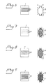
- Figure 1 shows a section through a joint body reinforced in accordance with the invention
- Figure 2 shows a section throuch another embodiment of a joint body according to the invention.
- Figures 3-5 show additional alternate embodiments, Figure 4 in section, and Figures 3 and 5 in perspective views.
- Figures 6-9 show sections through further embodiments of a joint body according to the invention with the "a" Figures showing transverse sections and the "b” Figures showing top view cross sections.
- Figure 10 is a perspective of a further embodiment of a joint body.
- Figure 11 is a top view cross section through yet another embodiment.
- Figure 12 is a top view cross section through a still further embodiment.
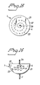
- Figure 13 is a top view of yet another embodiment of a joint body.
- Figure 14 is a side view thereof.
- a joint body is designated 1.
- the joint body 1 is provided with a pair of protruding pins 2 intended to cooperate with cavities arranged in the anchoring elements.
- joint body 1 may also be shaped without protruding pins if it is to be used as a joint mechanism for constructions described in United States patent application No. 406,587, filed September 13, 1989.
- the joint body 1 preferably comprises an elastomeric material, and in the embodiment according to Fig. 1 it is provided with reinforcement means 3 in the form of a number of fibers extending longitudinally through the mid-section between pins 2 and out into the pins.
- Reinforcement means 3 may consist, for instance, of titanium threads, carbon fibers, polymer fibers, cable-like twisted fibers, mesh of plastic or metal, suitably titanium, wowen inserts of biocompatible material, thin strips, or thin plates, of primarily biocompatible material, preferably titanium or the like.
- reinforcement means 3 consists of a wire 4 of titanium.
- reinforcement means 3 suitabley extends out into the pins 2.
- reinforcement means 3 has been embedded into the joint body 1 and the pins 2 by means of injection molding, so that the elastomeric material surrounds the reinforcement of the actual pins 2, as well.
- the reinforcement 3 has a special configuration in which the end portions 4 which are to form the pins 2 have been compressed an are, therefore, not necessarily embedded in the elastomeric material.
- Figs. 6-12 show some principles as to the structure of the reinforcement 3.
- the reinforcement 3 may consist of a number of thin strips 5, or plates 5, of titanium foil, for instance, arranged spaced from each other, their narrowing end portions 6 and 7 extending into the pins 2.
- the reinforcement 3 consists of a number of layers 8 of thin threads 9, the ends of which continue into the pins 2.
- the reinforcement 3 consists of one or more layers 10 of a net-like insert 11.
- one or more layers 10 of a woven material 11 are used to form the reinforcement 3.
- joint bodies 1 reinforced in such manner, can be governed as to direction and strength, depending on where the reinforcement is placed in the section and in which plane it is spread.
- the reinforcement may also be given various three-dimensional embodiments.
- the reinforcement may be arranged spirally around the joint body, i.e. it is a fiber 12 wrapped spirally around the pins at the ends of the body and around the body itself.
- the reinforcement may be on the joint body in some other suitable manner in order to achieve the desired optimization with respect to limited flexibility, compression, etc.
- the reinforcement can also be applied outside the actual joint body in the form of a spiral, as in Fig. 10, or the like.
- the fibers may run diagonally in the joint body itself as with the fibers 14, 15 in Fig. 11. Some fibers 14 are in the body and some fibers 15 extend from pin to pin.
- the entire joint body 1 with the reinforcement 16 located either outside or inside the body itself can be surrounded by a biocompatible sleeve 17 of titanium, for instance, suitably with slight clearance, so that the surrounding tissue is not affected directly by bending movements of the joint body.
- the joint body 1 has a generally half spherical shell 21 including a rounded body with a flat end wall 22.
- the shell surrounds and defines the shape of the elastomeric material body.
- the pin 2 at one end is integral with and of the material of the body 1.
- the pin 2a at the other end of the joint body projects out from the flat end wall 22 and is an integral end portion of the internal reinforcement 23, which is in the form of a helical coil which decreases in cross section toward the pin 2a,
- This embodiment has a special advantage in a joint. It permits a certain degree of rotation of the joint body with reference to the adjacent bone, to the extent permitted by the pins 2.
- the elastomeric material used for the joint body 1 may be a thermoplastic containing di-phenyl-sulphone groups, characterized by good elasticity, high durability and notch impact strength.
- a poly-sulphonic plastic marketed by Amoco Performance Products, Inc. under the trade name UDELL, designation P1700, is used. This poly-sulphonic plastic is produced by a nucleophillic substitution reaction between the di-sodium salt of Bis-phenol A and 4,4-di-chlor-di-phenyl sulphone. The chemical structure then has the following appearance:
- Ether and the isopropylide have been connected to the di-phenyl-sulphone group in order to give the material elasticity, as well as high strength.
- the material properties are as follows:
- Preferred tensile strength is between 50 and 90 N/mm2.
- Preferred modulus of elasticity is between 2000 and 2600 N/mm2.
- Preferred notch impact strength is between 40 and 80 J/n (with a material thickness of 2.8-15.0 mm).
- the polysulphonic plastic is inert with respect to the tissue fluid and is substantially impervious to water.
- the ability of the material to regain its original form after repeated, varying deformations is about at least 80%, that is, it does not fully restore to its original shape by itself.
- the notch impact strength stated above was measured with material thickness of between 2.8 and 15.0 mm.
Abstract
Description
- The present invention relates to an artificial, elastic joint mechanism intended for use in reconstructing joints such as finger joints, wrists, ankles, elbows, hip-joints, knees, toe joints and other joints in the human body. The joint mechanism can also be used to replace disc functions in the spine.
- A joint body for joint prostheses consisting entirely of an elastomeric material is described, for instance, in US Patent 3,875,594. This known body is provided with pins protruding from its opposing short sides and formed in one piece with the body, said pins being designed to fit into cavities in respective bone pipes. This direct anchoring of the joint body in the bone tissue has been found to give rise to serious drawbacks, such as undesired wear between the pins and the surrounding tissue upon movement of the joint, with consequent risk of inflammation and tissue damage.
- To eliminate the latter drawback, according to Swedish patent Application No. 87 04 211-5 corresponding to US Application No. 473,992, filed May 2, 1990 a combination is suggested comprising a mid section of resilient material arranged as a joint body between a pair of pins, the pins being attached by means of flanges embedded in the material and arranged transversely to the pins, and a tubular screw for each pin which can be secured in the bone, into which the pin is inserted, the pins and screws consisting of a biocompatible material. This construction has enabled better anchoring of the joint prosthesis in the bone pipes than was possible in the construction according to US Patent 3,875,594 mentioned above.
- However, it has been found that the joint body used in both the above-mentioned constructions, which consists of silicon rubber or polyurethane, is not satisfactory with respect to the expectations which must be placed on such an artificial joint. First of all, there is considerable risk of tissue damage and inflammation due to the constant movement of the pins in the tissue or in the attachment member. Furthermore, it has been found in practice that the joint body itself is not sufficiently strong in the environment in which it is used. A certain bending resistance is desired in such joint bodies, i.e. a more or less directed bending function, in order to emulate the normal function of a joint as much as possible.
- An object of the present invention, therefore, is to achieve a joint body which is more durable in use, and which can be optimally adjusted to the bending function of the joint it is replacing.
- This and other objects are achieved by providing an artificial joint mechanism for replacing a natural joint comprising a joint body which includes a flexible mid-section, connecting means for connecting said joint body to bone tissue and reinforcement means for resiliently maintaining in said joint body in its original shape following repeated deformations of said joint body in its main bending direction, said reinforcement means connected to at least said flexible mid-section.
- According to a suitable embodiment of the invention, the mid-section with protruding pins, if any, consists of a thermoplast containing di-phenyl-sulphone groups of the type

- The material proposed, according to the invention, has the ability to return to its original form to at least 80 % after repeated, varying deformations. That means that it will not return 100% to its origianl shape but nearly to that shape, i.e. about at least 80 %.
- According to a preferred embodiment of the invention, the reinforcement consists of a number of fibers embedded longitudinally in the mid-section, said fibers extending along the direction of movement of the mid-section and continuing into the pins.
- The reinforcement may suitably be comprised of titanium threads, carbon fibers, polymer fibers, cable-like twisted fibers, a mesh of plastic or metal, suitably titanium, woven inserts of biocompatible material, relatively thin strips or plates of primarily biocompatible material, preferably titanium, and the like.
- The reinforcement of a selected material may suitably be in the form of a number of layers of pre-fabricated strips, plates, or net-like inserts arranged one on top of the other, with spacing between, along the mid-section, the narrowing end portions of those layers, strips, etc., extending into the end pins.
- In order to obtain special joint effects, a part of the reinforcement may be arranged transverse to the normal direction of movement of the joint, or as a three-dimensonal space pattern with certain diagonal reinforcements in the joint body.
- The reinforcement can also be arranged outside the actual joint body in the form of a spiral coil surrounding at least the mid-section. In another embodiment the spiral or helix is embedded in the joint body mid-section.
- So as not to affect the surrounding tissue, the joint mechanism may be arranged in a sleeve-shaped outer casing surrounding at least the mid-section. That outer casing may be suitably comprised of titatium.
- The joint body mid-section typically is of an elongate, generally similar cross section shape, with thickness variation for optimum support and bendability. In one preferred embodiment, the body is generally half spherical, with the connecting means or end pins respecitvely projecting from the flat side and the rounded side of the joint body mid-section.
- The joint mechanism described herein includes reinforcement to optimize flexibility in the main bending direction of the reconstructed joint and/or pivotability of the joint mechanism.
- Other features and advantages of the present invention will become apparent from the following description of the invention which refers to the accompanying drawings.
- Figure 1 shows a section through a joint body reinforced in accordance with the invention;
- Figure 2 shows a section throuch another embodiment of a joint body according to the invention; and
- Figures 3-5 show additional alternate embodiments, Figure 4 in section, and Figures 3 and 5 in perspective views.
- Figures 6-9 show sections through further embodiments of a joint body according to the invention with the "a" Figures showing transverse sections and the "b" Figures showing top view cross sections.
- Figure 10 is a perspective of a further embodiment of a joint body.
- Figure 11 is a top view cross section through yet another embodiment.
- Figure 12 is a top view cross section through a still further embodiment.
- Figure 13 is a top view of yet another embodiment of a joint body.
- Figure 14 is a side view thereof.
- Referring to the drawings, a joint body is designated 1. When the
joint body 1 is used together with anchoring elements screwed into respective bones, thejoint body 1 is provided with a pair of protrudingpins 2 intended to cooperate with cavities arranged in the anchoring elements. - However, the
joint body 1 may also be shaped without protruding pins if it is to be used as a joint mechanism for constructions described in United States patent application No. 406,587, filed September 13, 1989. - The
joint body 1 preferably comprises an elastomeric material, and in the embodiment according to Fig. 1 it is provided with reinforcement means 3 in the form of a number of fibers extending longitudinally through the mid-section betweenpins 2 and out into the pins. - Reinforcement means 3 may consist, for instance, of titanium threads, carbon fibers, polymer fibers, cable-like twisted fibers, mesh of plastic or metal, suitably titanium, wowen inserts of biocompatible material, thin strips, or thin plates, of primarily biocompatible material, preferably titanium or the like.
- In the embodiment according to Fig. 2, reinforcement means 3 consists of a wire 4 of titanium. Here, also, reinforcement means 3 suitabley extends out into the
pins 2. - In the embodiments according to Figs. 1 and 2, reinforcement means 3 has been embedded into the
joint body 1 and thepins 2 by means of injection molding, so that the elastomeric material surrounds the reinforcement of theactual pins 2, as well. - In the embodiment according to Figs. 3, 4 and 5, the
reinforcement 3 has a special configuration in which the end portions 4 which are to form thepins 2 have been compressed an are, therefore, not necessarily embedded in the elastomeric material. - Figs. 6-12 show some principles as to the structure of the
reinforcement 3. - According to Figs. 6a and b, thus, the
reinforcement 3 may consist of a number ofthin strips 5, orplates 5, of titanium foil, for instance, arranged spaced from each other, their narrowingend portions 6 and 7 extending into thepins 2. - According to Figs. 7a and b, the
reinforcement 3 consists of a number oflayers 8 ofthin threads 9, the ends of which continue into thepins 2. - According to Figs. 8a and b, the
reinforcement 3 consists of one ormore layers 10 of a net-like insert 11. - According to Figs. 9a and b, one or
more layers 10 of awoven material 11 are used to form thereinforcement 3. - The flexibility and elasticity of
joint bodies 1, reinforced in such manner, can be governed as to direction and strength, depending on where the reinforcement is placed in the section and in which plane it is spread. - Depending on the desired degree of flexibility, control, etc., the reinforcement may also be given various three-dimensional embodiments. For instance, according to Fig. 10, the reinforcement may be arranged spirally around the joint body, i.e. it is a
fiber 12 wrapped spirally around the pins at the ends of the body and around the body itself. The reinforcement may be on the joint body in some other suitable manner in order to achieve the desired optimization with respect to limited flexibility, compression, etc. - The reinforcement can also be applied outside the actual joint body in the form of a spiral, as in Fig. 10, or the like. The fibers may run diagonally in the joint body itself as with the
fibers fibers 14 are in the body and somefibers 15 extend from pin to pin. - As in Fig. 12, the entire
joint body 1 with thereinforcement 16 located either outside or inside the body itself can be surrounded by abiocompatible sleeve 17 of titanium, for instance, suitably with slight clearance, so that the surrounding tissue is not affected directly by bending movements of the joint body. - In the embodiment of Figs. 13 and 14, the
joint body 1 has a generally halfspherical shell 21 including a rounded body with aflat end wall 22. The shell surrounds and defines the shape of the elastomeric material body. Thepin 2 at one end is integral with and of the material of thebody 1. Thepin 2a at the other end of the joint body projects out from theflat end wall 22 and is an integral end portion of theinternal reinforcement 23, which is in the form of a helical coil which decreases in cross section toward thepin 2a, This embodiment has a special advantage in a joint. It permits a certain degree of rotation of the joint body with reference to the adjacent bone, to the extent permitted by thepins 2. - According to a preferred embodiment of the invention, the elastomeric material used for the
joint body 1 may be a thermoplastic containing di-phenyl-sulphone groups, characterized by good elasticity, high durability and notch impact strength. In the present example, a poly-sulphonic plastic marketed by Amoco Performance Products, Inc. under the trade name UDELL, designation P1700, is used. This poly-sulphonic plastic is produced by a nucleophillic substitution reaction between the di-sodium salt of Bis-phenol A and 4,4-di-chlor-di-phenyl sulphone. The chemical structure then has the following appearance:
- The most important consituent is the di-phenyl sulphone group

- Ether and the isopropylide have been connected to the di-phenyl-sulphone group in order to give the material elasticity, as well as high strength. The material properties are as follows:
- Tensile strength
- 70 N/mm²
- Tension modulus
- 2480 N/mm²
- Impact strength
- 40 Kj/m²
- Preferred tensile strength is between 50 and 90 N/mm². Preferred modulus of elasticity is between 2000 and 2600 N/mm². Preferred notch impact strength is between 40 and 80 J/n (with a material thickness of 2.8-15.0 mm).
- It should also be pointed out here that the polysulphonic plastic is inert with respect to the tissue fluid and is substantially impervious to water. The ability of the material to regain its original form after repeated, varying deformations is about at least 80%, that is, it does not fully restore to its original shape by itself. The notch impact strength stated above was measured with material thickness of between 2.8 and 15.0 mm.
- The invention is, of course, not limited to the embodiments described above and the reinfrocements can be effected in many ways in order to provide optimal joint function for every occasion. Although the present invention has been described in relation to particular embodiments thereof, many other variations and modifications and other uses will become apparent to those skilled in the art. It is preferred, therefore, that the present invention be limited not by the specific disclosures herein, but only by the appended claims.
Claims (26)
- An artificial joint mechanism for replacing a natural joint and comprising a joint body (1) which includes a flexible mid-section, connecting means (2) for connecting said joint body (1) to bone tissue, and reinforcement means (3) in at least said flexible mid-section for optimizing flexibility of said mid-section in the main bending direction of the joint mechanism and/or the pivotability of the joint mechanism.
- The artificial joint mechanism of claim 1, wherein said connecting means (2) comprises a pair of pins connected to said flexible mid-section and protruding therefrom for cooperation with anchoring members implanted in the bone tissue on each side of the joint.
- The artificial joint mechanism of claim 1, wherein said reinforcement means (3) is shaped and comprised of a material for resiliently maintaining said joint body (1) in its original shape following repeated deformations of said joint body (1) in its main bending direction.
- The artificial joint mechanism of claim 1, wherein said mid-section is comprised of an elastomeric material.
- The artificial joint mechanism of claim 4, wherein said mid-section is comprised of a thermoplastic containing di-phenyl-sulphone groups of the type

- The artificial joint mechanism of claim 5, wherein said mid-section has an ability to return to its original form of at least 80% after repeated, varying deformations.
- The artificial joint mechanism of claim 4, wherein said mid-section has an ability to return to its original form of at least 80% after repeated, varying deformations.
- The artificial joint mechanism of claim 5, wherein said mid-section is comprised of a polymeric material having a tensile strength of between 50 and 90 N/mm², a modulus of elasticity of between 2000 and 2600 N/mm² and a notch impact strength of between 40 and 80 J/n (with a material thickness of 2.8-15.0 mm).
- The artificial joint mechanism of claim 4, wherein said mid-section is comprised of a polymeric material having a tensile strength of between 50 and 90 N/mm², a modulus of elasticity of between 2000 and 2600 N/mm² and a notch impact strength of between 40 and 80 J/n (with a material thickness of 2.8-15.0 mm).
- The artificial joint mechanism of claim 3, wherein said mid-section is comprised of a polymeric material having a tensile strength of between 50 and 90 N/mm², a modulus of elasticity of between 2000 and 2600 N/mm² and a notch impact strength of between 40 and 80 J/n (with a material thickness of 2.8-15.0 mm).
- The artificial joint mechanism of claim 2, wherein said mid-section and pins are comprised of a polymeric material having a tensile strength of between 50 and 90 N/mm², a modulus of elasticity of between 2000 and 2600 N/mm² and a notch impact strength of between 40 and 80 J/n (with a material thickness of 2.8-15.0 mm).
- The artificial joint mechanism of claim 1, wherein said reinforcement means (3) comprises at least one fiber embedded in and extending longitudinally along said mid-section and extending along a direction of movement of said mid-section.
- The artificial joint mechanism of claim 1, wherein said reinforcement means (3) comprises at least one reinforcement element extending along said joint body (1) selected from the group consisting of titanium threads, carbon fibers, polymer fibers, cable-like twisted fibers, plastic or metal mesh, woven inserts comprising biocompatible material, and thin strips or plates comprising biocompatible material.
- The artificial joint mechanism of claim 1, wherein said reinforcement means (3) comprises a plurality of layers of a reinforcement element selected from the group consisting of prefabricated strips, plates and net-like inserts, whereing said layers are substantially parallel to and spaced from each other wherein said layers extend through said mid-section and into said connecting means (2).
- The artificial joint mechanism of claim 14, wherein said connecting means (3) are narrower in cross section than said mid-section and wherein said layers are narrower in said connecting means (3) than in said mid-section.
- The artificial joint mechanism of claim 1, wherein said reinforcement means (3) includes a reinforcement element transverse to a normal direction of movement for said joint.
- The artificial joint mechanism of claim 1, wherein said means includes a reinforcement means (3) which spreads in three dimensions in said joint body (1).
- The artificial joint mechanism of claim 1, wherein said reinforcement means (3) is a spiral coil surrounding said mid-section.
- The artificial joint mechanism of claim 1, further comprising a sleeve-shaped outer casing surrounding at least said mid-section.
- The artificial joint mechanism of claim 19, wherein said outer casing comprises titanium.
- The artificial joint mechanism of claim 1, wherein said reinforcement means (3) comprises a plurality of reinforcing elements extending through said joint body (1) and at least one of said elements being in a plane diagonal to said joint body (1).
- The artificial jont mechanism of claim 4, wherein said body is generally half spherical in shape with a flat side, and one of said connecting means (2) extending out of said flat side; said body having a rounded side and another of said connecting means (2) projecting from said rounded side.
- The artificial joint mechanism of claim 1, wherein said body is generally half spherical in shape with a flat side, and one of said connecting means (2) extending out of said flat side; said body having a rounded side and another of said connecting means (2) projecting from said rounded side.
- The artificial joint mechanism of claim 23, wherein said reinforcement means (3) comprises a helically coiled wire in said body and the helix of said coil extending toward said connecting means (2).
- The artificial joint mechanism of claim 24, wherein said coil is wound wider in diamter toward said rounded side of said body and is wound gradually smaller in diameter toward said flat side of said body.
- The artificial joint mechanism of claim 25, wherein said connecting means (2) at said flat side of said body is a pin integral with said coil.
Applications Claiming Priority (2)
| Application Number | Priority Date | Filing Date | Title |
|---|---|---|---|
| SE9001430A SE9001430D0 (en) | 1990-04-23 | 1990-04-23 | ARTIFICIAL LED MECHANISM |
| SE9001430 | 1990-04-23 |
Publications (2)
| Publication Number | Publication Date |
|---|---|
| EP0454645A1 true EP0454645A1 (en) | 1991-10-30 |
| EP0454645B1 EP0454645B1 (en) | 1994-11-23 |
Family
ID=20379243
Family Applications (1)
| Application Number | Title | Priority Date | Filing Date |
|---|---|---|---|
| EP91850102A Expired - Lifetime EP0454645B1 (en) | 1990-04-23 | 1991-04-23 | Artificial joint mechanism |
Country Status (6)
| Country | Link |
|---|---|
| EP (1) | EP0454645B1 (en) |
| AT (1) | ATE114235T1 (en) |
| AU (1) | AU7760491A (en) |
| DE (1) | DE69105234D1 (en) |
| SE (1) | SE9001430D0 (en) |
| WO (1) | WO1991016014A1 (en) |
Cited By (17)
| Publication number | Priority date | Publication date | Assignee | Title |
|---|---|---|---|---|
| EP0737050A1 (en) * | 1993-12-28 | 1996-10-16 | D. Kenneth Walston | Joint prosthesis having ptfe cushion |
| FR2744627A1 (en) * | 1996-02-09 | 1997-08-14 | Bouvet Jean Claude | Prosthesis for restoring articulation between two bones, e.g. intervertebral prosthesis |
| WO1998047449A1 (en) * | 1997-04-18 | 1998-10-29 | W.L. Gore & Associates, Inc. | Resorbable interposition arthroplasty implant |
| WO1998056317A1 (en) * | 1997-06-11 | 1998-12-17 | Bionx Implants Oy | Joint prosthesis |
| US5879396A (en) * | 1993-12-28 | 1999-03-09 | Walston; D. Kenneth | Joint prosthesis having PTFE cushion |
| EP1153623A1 (en) * | 2000-05-08 | 2001-11-14 | Tyco Healthcare Group Lp | Reusable nonmetallic cannula |
| US6342076B1 (en) | 1996-01-22 | 2002-01-29 | Handevelop Ab | Prosthetic device for joints |
| WO2002069853A1 (en) * | 2001-03-02 | 2002-09-12 | Guerard Jean-Louis | Wrist prosthesis |
| US6551343B1 (en) | 1998-04-01 | 2003-04-22 | Bionx Implants, Oy | Bioabsorbable surgical fastener for tissue treatment |
| US6692499B2 (en) | 1997-07-02 | 2004-02-17 | Linvatec Biomaterials Oy | Surgical fastener for tissue treatment |
| US7571453B2 (en) | 1998-08-21 | 2009-08-04 | United Video Properties, Inc. | Apparatus and method for constrained selection of favorite channels |
| CN106466204A (en) * | 2015-08-18 | 2017-03-01 | 瑞特医疗技术公司 | Articulating implant, its manufacture method and for implanting its surgical operation |
| US9839453B2 (en) | 2007-03-20 | 2017-12-12 | Stryker European Holdings I, Llc | Osteosynthesis device |
| US10022167B2 (en) | 2005-04-14 | 2018-07-17 | Stryker European Holdings I, Llc | Method of osteosyntheses or arthrodesis of two-bone parts, in particular of the hand and / or foot |
| EP3344193A4 (en) * | 2015-09-03 | 2018-11-21 | CMC Sert Ltd. | Prosthesis for replacing joint in a human hand or foot |
| US10383671B2 (en) | 2008-09-09 | 2019-08-20 | Stryker European Holdings I, Llc | Resorptive intramedullary implant between two bones or two bone fragments |
| US10470807B2 (en) | 2016-06-03 | 2019-11-12 | Stryker European Holdings I, Llc | Intramedullary implant and method of use |
Families Citing this family (2)
| Publication number | Priority date | Publication date | Assignee | Title |
|---|---|---|---|---|
| FI101933B1 (en) * | 1995-06-13 | 1998-09-30 | Biocon Oy | A joint prosthesis |
| GB0219758D0 (en) | 2002-08-24 | 2002-10-02 | Grampian Univ Hospitals | Device |
Citations (7)
| Publication number | Priority date | Publication date | Assignee | Title |
|---|---|---|---|---|
| DE1960087A1 (en) * | 1969-01-27 | 1970-07-30 | Cutter Lab | Artificial joint for human and veterinary use |
| FR2244445A1 (en) * | 1973-09-26 | 1975-04-18 | Joint Prosthesis Cutter Labora | |
| US3955282A (en) * | 1975-03-03 | 1976-05-11 | Mcnall Earl G | Process of mounting orthodontic bracket to tooth |
| US3990116A (en) * | 1974-10-17 | 1976-11-09 | Fixel Irving E | Pretensioned prosthetic device for skeletal joints |
| US4313232A (en) * | 1979-01-10 | 1982-02-02 | Habal Mutaz B | An elastomeric mesh hinge primarily for replacement of the finger joints |
| EP0057597A2 (en) * | 1981-01-30 | 1982-08-11 | Oec Europe Limited | A joint prosthesis |
| GB2169512A (en) * | 1985-01-10 | 1986-07-16 | Trade & Industry The Secretary | Joint prosthesis |
Family Cites Families (1)
| Publication number | Priority date | Publication date | Assignee | Title |
|---|---|---|---|---|
| US3886600A (en) * | 1971-07-15 | 1975-06-03 | Cutter Lab | Joint prosthesis |
-
1990
- 1990-04-23 SE SE9001430A patent/SE9001430D0/en unknown
-
1991
- 1991-04-23 AT AT91850102T patent/ATE114235T1/en not_active IP Right Cessation
- 1991-04-23 WO PCT/SE1991/000286 patent/WO1991016014A1/en unknown
- 1991-04-23 EP EP91850102A patent/EP0454645B1/en not_active Expired - Lifetime
- 1991-04-23 AU AU77604/91A patent/AU7760491A/en not_active Abandoned
- 1991-04-23 DE DE69105234T patent/DE69105234D1/en not_active Expired - Lifetime
Patent Citations (7)
| Publication number | Priority date | Publication date | Assignee | Title |
|---|---|---|---|---|
| DE1960087A1 (en) * | 1969-01-27 | 1970-07-30 | Cutter Lab | Artificial joint for human and veterinary use |
| FR2244445A1 (en) * | 1973-09-26 | 1975-04-18 | Joint Prosthesis Cutter Labora | |
| US3990116A (en) * | 1974-10-17 | 1976-11-09 | Fixel Irving E | Pretensioned prosthetic device for skeletal joints |
| US3955282A (en) * | 1975-03-03 | 1976-05-11 | Mcnall Earl G | Process of mounting orthodontic bracket to tooth |
| US4313232A (en) * | 1979-01-10 | 1982-02-02 | Habal Mutaz B | An elastomeric mesh hinge primarily for replacement of the finger joints |
| EP0057597A2 (en) * | 1981-01-30 | 1982-08-11 | Oec Europe Limited | A joint prosthesis |
| GB2169512A (en) * | 1985-01-10 | 1986-07-16 | Trade & Industry The Secretary | Joint prosthesis |
Cited By (31)
| Publication number | Priority date | Publication date | Assignee | Title |
|---|---|---|---|---|
| EP0737050A4 (en) * | 1993-12-28 | 1997-11-19 | D Kenneth Walston | Joint prosthesis having ptfe cushion |
| US5879396A (en) * | 1993-12-28 | 1999-03-09 | Walston; D. Kenneth | Joint prosthesis having PTFE cushion |
| EP0737050A1 (en) * | 1993-12-28 | 1996-10-16 | D. Kenneth Walston | Joint prosthesis having ptfe cushion |
| US6342076B1 (en) | 1996-01-22 | 2002-01-29 | Handevelop Ab | Prosthetic device for joints |
| FR2744627A1 (en) * | 1996-02-09 | 1997-08-14 | Bouvet Jean Claude | Prosthesis for restoring articulation between two bones, e.g. intervertebral prosthesis |
| FR2761878A1 (en) * | 1996-02-09 | 1998-10-16 | Jean Claude Bouvet | Prosthesis for restoration of hip joint |
| WO1998047449A1 (en) * | 1997-04-18 | 1998-10-29 | W.L. Gore & Associates, Inc. | Resorbable interposition arthroplasty implant |
| US6017366A (en) * | 1997-04-18 | 2000-01-25 | W. L. Gore & Associates, Inc. | Resorbable interposition arthroplasty implant |
| EP1356794A3 (en) * | 1997-06-11 | 2003-11-05 | Bionx Implants Oy | Joint prosthesis |
| WO1998056317A1 (en) * | 1997-06-11 | 1998-12-17 | Bionx Implants Oy | Joint prosthesis |
| US6113640A (en) * | 1997-06-11 | 2000-09-05 | Bionx Implants Oy | Reconstructive bioabsorbable joint prosthesis |
| US6692499B2 (en) | 1997-07-02 | 2004-02-17 | Linvatec Biomaterials Oy | Surgical fastener for tissue treatment |
| US6551343B1 (en) | 1998-04-01 | 2003-04-22 | Bionx Implants, Oy | Bioabsorbable surgical fastener for tissue treatment |
| US7571453B2 (en) | 1998-08-21 | 2009-08-04 | United Video Properties, Inc. | Apparatus and method for constrained selection of favorite channels |
| US7937727B2 (en) | 1998-08-21 | 2011-05-03 | United Video Properties, Inc. | Apparatus and method for constrained selection of favorite channels |
| US7779440B2 (en) | 1998-08-21 | 2010-08-17 | United Video Properties, Inc. | Apparatus and method for constrained selection of favorite channels |
| US6740064B1 (en) | 2000-05-08 | 2004-05-25 | Tyco Healthcare Group Lp | Reusable nonmetallic cannula |
| EP1153623A1 (en) * | 2000-05-08 | 2001-11-14 | Tyco Healthcare Group Lp | Reusable nonmetallic cannula |
| US7563287B2 (en) | 2001-03-02 | 2009-07-21 | Guerard Jean-Louis | Wrist prosthesis |
| WO2002069853A1 (en) * | 2001-03-02 | 2002-09-12 | Guerard Jean-Louis | Wrist prosthesis |
| US11478285B2 (en) | 2005-04-14 | 2022-10-25 | Stryker European Operations Holdings Llc | Device for osteosyntheses or arthrodesis of two-bone parts, in particular of the hand and/or foot |
| US10022167B2 (en) | 2005-04-14 | 2018-07-17 | Stryker European Holdings I, Llc | Method of osteosyntheses or arthrodesis of two-bone parts, in particular of the hand and / or foot |
| US11006984B2 (en) | 2005-04-14 | 2021-05-18 | Stryker European Operations Holdings Llc | Device for osteosyntheses or arthrodesis of two-bone parts, in particular of the hand and / or foot |
| US10912594B2 (en) | 2007-03-20 | 2021-02-09 | Stryker European Holdings I, Llc | Osteosynthesis device |
| US9839453B2 (en) | 2007-03-20 | 2017-12-12 | Stryker European Holdings I, Llc | Osteosynthesis device |
| US10383671B2 (en) | 2008-09-09 | 2019-08-20 | Stryker European Holdings I, Llc | Resorptive intramedullary implant between two bones or two bone fragments |
| CN106466204A (en) * | 2015-08-18 | 2017-03-01 | 瑞特医疗技术公司 | Articulating implant, its manufacture method and for implanting its surgical operation |
| EP3141221A1 (en) * | 2015-08-18 | 2017-03-15 | Wright Medical Technology, Inc. | Implant and method for making such an implant |
| EP3344193A4 (en) * | 2015-09-03 | 2018-11-21 | CMC Sert Ltd. | Prosthesis for replacing joint in a human hand or foot |
| US10470807B2 (en) | 2016-06-03 | 2019-11-12 | Stryker European Holdings I, Llc | Intramedullary implant and method of use |
| US11272966B2 (en) | 2016-06-03 | 2022-03-15 | Stryker European Operations Holdings Llc | Intramedullary implant and method of use |
Also Published As
| Publication number | Publication date |
|---|---|
| SE9001430D0 (en) | 1990-04-23 |
| AU7760491A (en) | 1991-11-11 |
| ATE114235T1 (en) | 1994-12-15 |
| WO1991016014A1 (en) | 1991-10-31 |
| DE69105234D1 (en) | 1995-01-05 |
| EP0454645B1 (en) | 1994-11-23 |
Similar Documents
| Publication | Publication Date | Title |
|---|---|---|
| EP0454645A1 (en) | Artificial joint mechanism | |
| US5004474A (en) | Prosthetic anterior cruciate ligament design | |
| CA1112401A (en) | Deformable high energy storage tension spring | |
| US5306310A (en) | Vertebral prosthesis | |
| US6113640A (en) | Reconstructive bioabsorbable joint prosthesis | |
| AU605759B2 (en) | Prosthetic ligament | |
| US3176316A (en) | Plastic prosthetic tendon | |
| JP4240399B2 (en) | Intervertebral implant | |
| RU2370234C2 (en) | Element of dynamic connection for system of spine fixation and system of fixation, containing such element | |
| JP2833718B2 (en) | Metal / composite hybrid orthopedic implant | |
| JP2843676B2 (en) | Orthopedic composite implant | |
| US6371982B2 (en) | Graft structures with compliance gradients | |
| DE69433268T2 (en) | STENT | |
| EP0808613A1 (en) | Tubular prosthesis made of curable material | |
| ZA922584B (en) | Composite orthopedic implant | |
| KR19990081884A (en) | Joint prosthetic devices | |
| EP1952829A2 (en) | Designed composite degradation for spinal implants | |
| JPH0817786B2 (en) | Beam structure and method | |
| EP0977524A1 (en) | Bone-growth promoting implant | |
| EP1629796A2 (en) | Implant for surgical use in humans or vertebrates | |
| JPS61501616A (en) | Orthopedic instruments and their manufacturing method | |
| WO2007114769A1 (en) | Prosthetic device for joints | |
| US4177805A (en) | Penile implantation prosthesis | |
| SK4792001A3 (en) | Implant for implantation in humans or animals comprising flexible, thread-shaped elements | |
| RU2020900C1 (en) | Surgical implant blank and method of producing same |
Legal Events
| Date | Code | Title | Description |
|---|---|---|---|
| PUAI | Public reference made under article 153(3) epc to a published international application that has entered the european phase |
Free format text: ORIGINAL CODE: 0009012 |
|
| AK | Designated contracting states |
Kind code of ref document: A1 Designated state(s): AT BE CH DE DK ES FR GB GR IT LI LU NL SE |
|
| 17P | Request for examination filed |
Effective date: 19911119 |
|
| 17Q | First examination report despatched |
Effective date: 19930318 |
|
| GRAA | (expected) grant |
Free format text: ORIGINAL CODE: 0009210 |
|
| AK | Designated contracting states |
Kind code of ref document: B1 Designated state(s): AT BE CH DE DK ES FR GB GR IT LI LU NL SE |
|
| PG25 | Lapsed in a contracting state [announced via postgrant information from national office to epo] |
Ref country code: IT Free format text: LAPSE BECAUSE OF FAILURE TO SUBMIT A TRANSLATION OF THE DESCRIPTION OR TO PAY THE FEE WITHIN THE PRE;WARNING: LAPSES OF ITALIAN PATENTS WITH EFFECTIVE DATE BEFORE 2007 MAY HAVE OCCURRED AT ANY TIME BEFORE 2007. THE CORRECT EFFECTIVE DATE MAY BE DIFFERENT FROM THE ONE RECORDED.SCRIBED TIME-LIMIT Effective date: 19941123 Ref country code: ES Free format text: THE PATENT HAS BEEN ANNULLED BY A DECISION OF A NATIONAL AUTHORITY Effective date: 19941123 Ref country code: FR Effective date: 19941123 Ref country code: DK Effective date: 19941123 Ref country code: GR Free format text: LAPSE BECAUSE OF FAILURE TO SUBMIT A TRANSLATION OF THE DESCRIPTION OR TO PAY THE FEE WITHIN THE PRESCRIBED TIME-LIMIT Effective date: 19941123 Ref country code: CH Effective date: 19941123 Ref country code: NL Effective date: 19941123 Ref country code: AT Effective date: 19941123 Ref country code: LI Effective date: 19941123 Ref country code: BE Effective date: 19941123 |
|
| REF | Corresponds to: |
Ref document number: 114235 Country of ref document: AT Date of ref document: 19941215 Kind code of ref document: T |
|
| REF | Corresponds to: |
Ref document number: 69105234 Country of ref document: DE Date of ref document: 19950105 |
|
| PG25 | Lapsed in a contracting state [announced via postgrant information from national office to epo] |
Ref country code: SE Effective date: 19950223 |
|
| PG25 | Lapsed in a contracting state [announced via postgrant information from national office to epo] |
Ref country code: DE Effective date: 19950224 |
|
| REG | Reference to a national code |
Ref country code: CH Ref legal event code: PL |
|
| EN | Fr: translation not filed | ||
| PG25 | Lapsed in a contracting state [announced via postgrant information from national office to epo] |
Ref country code: LU Free format text: LAPSE BECAUSE OF NON-PAYMENT OF DUE FEES Effective date: 19950430 |
|
| NLV1 | Nl: lapsed or annulled due to failure to fulfill the requirements of art. 29p and 29m of the patents act | ||
| PLBE | No opposition filed within time limit |
Free format text: ORIGINAL CODE: 0009261 |
|
| STAA | Information on the status of an ep patent application or granted ep patent |
Free format text: STATUS: NO OPPOSITION FILED WITHIN TIME LIMIT |
|
| 26N | No opposition filed | ||
| REG | Reference to a national code |
Ref country code: GB Ref legal event code: IF02 |
|
| PGFP | Annual fee paid to national office [announced via postgrant information from national office to epo] |
Ref country code: GB Payment date: 20020409 Year of fee payment: 12 |
|
| PG25 | Lapsed in a contracting state [announced via postgrant information from national office to epo] |
Ref country code: GB Free format text: LAPSE BECAUSE OF NON-PAYMENT OF DUE FEES Effective date: 20030423 |
|
| GBPC | Gb: european patent ceased through non-payment of renewal fee |
Effective date: 20030423 |