EP0455431B1 - Liquid dispensing system including a discharge assembly providing a positive air flow condition - Google Patents
Liquid dispensing system including a discharge assembly providing a positive air flow condition Download PDFInfo
- Publication number
- EP0455431B1 EP0455431B1 EP91303793A EP91303793A EP0455431B1 EP 0455431 B1 EP0455431 B1 EP 0455431B1 EP 91303793 A EP91303793 A EP 91303793A EP 91303793 A EP91303793 A EP 91303793A EP 0455431 B1 EP0455431 B1 EP 0455431B1
- Authority
- EP
- European Patent Office
- Prior art keywords
- liquid
- container
- discharge
- nipple
- opening
- Prior art date
- Legal status (The legal status is an assumption and is not a legal conclusion. Google has not performed a legal analysis and makes no representation as to the accuracy of the status listed.)
- Expired - Lifetime
Links
Images


Classifications
-
- A—HUMAN NECESSITIES
- A47—FURNITURE; DOMESTIC ARTICLES OR APPLIANCES; COFFEE MILLS; SPICE MILLS; SUCTION CLEANERS IN GENERAL
- A47K—SANITARY EQUIPMENT NOT OTHERWISE PROVIDED FOR; TOILET ACCESSORIES
- A47K5/00—Holders or dispensers for soap, toothpaste, or the like
- A47K5/06—Dispensers for soap
- A47K5/12—Dispensers for soap for liquid or pasty soap
- A47K5/1202—Dispensers for soap for liquid or pasty soap dispensing dosed volume
- A47K5/1208—Dispensers for soap for liquid or pasty soap dispensing dosed volume by means of a flexible dispensing chamber
- A47K5/1209—Dispensers for soap for liquid or pasty soap dispensing dosed volume by means of a flexible dispensing chamber with chamber in the form of a cylindrical tube
-
- B—PERFORMING OPERATIONS; TRANSPORTING
- B67—OPENING, CLOSING OR CLEANING BOTTLES, JARS OR SIMILAR CONTAINERS; LIQUID HANDLING
- B67D—DISPENSING, DELIVERING OR TRANSFERRING LIQUIDS, NOT OTHERWISE PROVIDED FOR
- B67D1/00—Apparatus or devices for dispensing beverages on draught
- B67D1/0042—Details of specific parts of the dispensers
- B67D1/0078—Ingredient cartridges
- B67D1/0079—Ingredient cartridges having their own dispensing means
Definitions
- the present invention relates to apparatus for dispensing liquid, normally in discrete small quantities or charges.
- the invention has particular application to the dispensing of liquid from replaceable cartridges which may contain grit for scouring purposes.
- U.S. patent no. 4,108,363 includes a flexible pump bowl which receives soap from a container through a diaphragm-type check valve. When the bowl is compressed it closes the check valve and forces the soap in the bowl out through a passageway to a discharge outlet.
- This structure is relatively complex and is not well suited to modern distribution networks which require field maintenance by unskilled laborers, nor is it suited to the dispensing of soap containing grit, since the grit tends to clog the passageways in the device thereby increasing maintenance problems.
- U.S. patent no. 1,326,880 the dispenser ejecting soap directly from a slit in the pump nipple.
- This dispenser utilizes a custom-made check valve stopper in the soap container outlet, and depends on distortion of the slit in the nipple for dispensing of soap therefrom.
- the nipple is compressed in the direction of the slit. This has the disadvantage that the slit can be opened permitting soap to drip therefrom before pressure in the nipple has been raised sufficiently to close the check valve.
- U.S. patent no. 4,646,945 issued to Robert L. Steiner et al, there is disclosed a vented discharge assembly for a liquid soap dispenser including a valved vent opening separate from the outlet opening for the liquid soap for providing a vent path through the discharge assembly while effectively preventing discharge of liquid soap through the vent path.
- a valved vent opening separate from the outlet opening for the liquid soap for providing a vent path through the discharge assembly while effectively preventing discharge of liquid soap through the vent path.
- Another vented discharge assembly for a liquid soap dispenser includes a semipermeable filter mounted between the discharge assembly and the soap container to introduce air into the soap container immediately upon withdrawal of soap from the container to permit rapid operation of the discharge assembly.
- the filter comprises a disc-shaped semi-permeable membrane installed in the air passageway which is offset radially from the liquid soap outlet opening.
- the air passageway has a relatively small cross section making it susceptible to becoming blocked as the result of soap drying on the filter membrane.
- anti-bootleg devices have been included in the dispenser mechanism to prevent the use of unauthorized cartridges therein.
- soap dispensers including anti-bootleg devices are disclosed, for instance, in Steiner et al U.S. patent nos. 4,391,309 and 4,429,812.
- these prior art soap dispensers employ a dispensing pump mechanism which is integral with the housing which defines a reservoir from which soap is drawn in use.
- the cartridge is adapted for mounting on the housing and supplies soap to the reservoir by gravity.
- the anti-bootleg mechanism comprises a plurality of keys located in the inlet opening of the reservoir which prevent proper seating of unauthorized cartridges.
- Another object of the invention is the provision of a discharge assembly for a liquid dispenser which is suitable for dispensing full discrete charges in rapid succession.
- a further object of the invention is the provision of a discharge assembly for a liquid dispenser which is of simple and economical construction, and is characterized by ease of assembly.
- Still another object of the invention is the provision of a discharge assembly for a liquid dispenser including a venting arrangement which ensures full dosage for rapid repeat operation of the discharge assembly.
- Yet another object of the invention is to provide a discharge assembly for a liquid dispenser including a venting arrangement which provides a more positive air flow condition than was provided by prior art venting arrangements.
- liquid dispenser as claimed in the ensuing claim 1, the preamble of claim 1 being already known from document US-A-4646945.
- the liquid dispensing system 20 comprises a dispenser 25 adapted to be mounted on an associated support surface 21, such as on a wall 22 and, more particularly, in a recess 23 therein (see FIGS. 3 and 4), and a disposable liquid cartridge 26 which contains a supply of liquid and is removably mountable on the dispenser 25 for cooperation therewith to control the dispensing of liquid therefrom.
- the liquid may be liquid soap, alcohol, gel, suntan oil, or any material that flows.
- the liquid cartridge includes a discharge assembly which allows mounting of the cartridge on the dispenser without specific orientation therebetween.
- the discharge assembly includes a filter which prevents contaminated air from entering the cartridge, which filter allows a more positive air flow condition than is provided by known liquid dispensing systems of the type which are vented through their outlet opening.
- the liquid dispenser includes an anti-bootleg structure for preventing unauthorized cartridges from being used with the dispenser, the anti-bootleg structure including an anti-bootleg device 28 secured to the dispenser and a cooperating surface configuration 29 for the cartridge neck, as will be described.
- the cartridge 26 is inexpensively manufactured so as to be disposable.
- the dispenser 25 includes a housing 30, which is preferably of unitary, one-piece construction and may be formed of molded plastic.
- the housing 30 is similar to the housing disclosed in United States patent no. 4,673,109, which is assigned to Steiner Corporation.
- the housing 30 includes a flat rectangular base wall 31 and an upstanding rectangular mounting wall 32 integral with the base wall 31 at the rear edge thereof and disposed substantially perpendicular thereto.
- the mounting wall 32 may have fastener holes 33 therethrough for receiving associated fasteners (not shown), securely to mount the housing 30 on the associated support surface 21.
- the housing 30 and cartridge 26 define mating edge surfaces providing a retaining system like that for the dispenser and cartridge illustrated in the referenced U.S. patent no. 4,673,109.
- a continuous peripheral flange 34 integral with the base wall 31 and extending upwardly therefrom along the front and side edges thereof, is a continuous peripheral flange 34, having a stepped down portion 34a on the front edge.
- Side flanges 35 are respectively integral with the side edges of the mounting wall 32 and project forwardly therefrom to join the peripheral flange 34.
- the cartridge 26 includes a liquid container 90 and a liquid discharge assembly 120 which is described in detail hereinbelow.
- the liquid container 90 is a generally box-like container, which may be formed of a suitable plastic material.
- the container 90 is generally in the form of a rectangular parallelepiped having a top wall 92, a bottom wall 93, a front wall 94, a rear wall 95 and a pair of opposed side walls 96.
- the front wall 94 and the side walls 96 are set back or recessed along their lower edges adjacent to their junction with the bottom wall 93 to define a support shoulder 97.
- the top wall 92 projects rearwardly a slight distance beyond the rear wall 95 to form an overhang which defines a stop flange 98.
- the lower portions of the grooves 100 are cut away, as at 101, so as to define lugs 102 adjacent to the upper ends of the grooves 100.
- the cartridge outer surfaces are all dimensioned so that when the cartridge 26 is in its use position on the dispenser the outer surfaces of the front wall and the side walls are, respectively, substantially coplanar with corresponding portions of the housing so as to present an attractive, smooth outward appearance.
- the retaining system formed by rails 36 and grooves 100 prevent forward tilting of the cartridge relative to the dispenser.
- a pair of laterally spaced-apart, upstanding support plates 37 integral with the base wall 31 and with the mounting wall 32 and substantially perpendicular to each are a pair of laterally spaced-apart, upstanding support plates 37, respectively provided with laterally aligned bearing notches 38 in the upper edges thereof (see FIG. 3).
- Formed in the base wall 31 is an elongated, generally rectangular opening 39 (FIGS. 3 and 4) which extends laterally between the support plates 37, the opening 39 having a rearwardly extending rectangular arm 39a and having an arcuate forward end.
- a receptacle 40 Integral with the housing 30 is a receptacle 40 having a peripheral wall 41 which lines the forward portion of the opening 39, the peripheral wall 41 having an arcuate front end and parallel side portions, which side portions are respectively parallel to the support plates 37 and are integral with the inner surfaces thereof at the front ends thereof.
- the peripheral wall 41 projects above and below the base wall 31 and is closed at its lower end by a bottom wall 42 which is disposed substantially parallel to the base wall 31.
- the bottom wall 42 has a circular opening 43 therein adjacent to the forward end thereof, and a generally T-shaped slot 44 therethrough (FIG. 3) just rearwardly of the circular opening 43.
- Respectively formed in the side portions of the peripheral wall 41 below the base wall 31 are two laterally aligned circular pivot openings 45 (FIG. 18).
- a stop web 48 laterally spans the side portions of the peripheral wall 41, extending a slight distance above and below the base wall 31, the web 48 having a rectangular notch 48a in the lower edge thereof and a forwardly directed ledge portion 48b near its upper end.
- a rectangular stop web 49 is formed integrally with and extends upwardly from the base wall 31.
- Web 49 is disposed substantially parallel to the stop web 48 and laterally spans the peripheral wall 41 near its arcuate front end. The upper edge of the stop web and the upper surface of the ledge portion 48b lie substantially in a common horizonal plane.
- Web 49 has a rearwardly directed boss 49a which is semi-cylindrical in shape and extends substantially the width of the web 49.
- the dispenser 25 also includes an actuator assembly 50 which is removably mounted in the housing 30.
- the actuator assembly 50 includes a handle 51 comprising a rectangular plate 52 provided at its upper end with an inclined portion 53, which is in turn provided at its distal end with laterally outwardly extending cylindrical pivot lugs 54.
- the pivot lugs 54 are respectively received in the bearing notches 38 for pivotally supporting the handle 51 which extends through opening 39 in the housing bottom, for movement between actuating and retracted positions.
- the plate 52 has a width slightly less than the width of the opening 39, so that the base wall 31 at the rear end of the opening 39 and the rear flanges 46 of the receptacle 40 provide rear and front stops to limit the pivotal movement of the handle 51.
- a rectangular recess 55 Formed in the front surface of the plate 52 is a rectangular recess 55, near the lower end of which is formed a rectangular slot 56 which extends through the thickness of the plate 52 midway between the side edges thereof and in position so as to be disposed below the base wall 31 when the handle 51 is disposed in its mounted condition in the housing 30.
- the actuator assembly 50 also includes a bias unit 60 which comprises a latch member 61 and a bias leaf 70.
- the latch member 61 is generally in the form of a clevis having a pair of parallel, spaced-apart arms 62, respectively provided with angled feet 63, at the lower ends thereof.
- the feet 63 are respectively provided with laterally outwardly extending circular cylindrical pivot lugs 64, each having a substantially square key socket 65 formed in the outer end thereof, which may extend laterally completely therethrough.
- Each of the feet 63 is also provided on its inner surface with a bearing boss 66.
- the arms 62 are interconnected at their upper ends by a bight portion 67 provided with a forwardly extending latch flange 68 having a part frustoconical cam surface 69 thereon which locks the cartridge in place on the dispenser.
- the latch member 61 is dimensioned to fit within the receptacle 40 with the arms 62 respectively disposed along the inner surfaces of the side portions of the peripheral wall 41.
- the arms 62 are resiliently deflected together to permit the pivot lugs 64 to clear the inner surfaces of the peripheral wall 41, and then the latch member 61 is lowered into the receptacle 40 until the pivot lugs 64 respectively snap out into the pivot openings 45 (FIG. 18 ), pivotally to mount the latch member 61.
- the length of the arms 62 is such that when the latch member 61 is in this mounted condition, the latch flange 68 is disposed a predetermined distance above the upper end of the receptacle 40.
- the bias leaf 70 comprises a thin, flat, rectangular band which is formed of a suitable flexible and resilient material, such as a suitable plastics material. One end of the bias leaf 70 is fixedly secured to the rear surface of the bight portion 67 of the latch member 61 by suitable means (not shown).
- the bias leaf 70 is fabricated with predetermined curvature therein, and is provided with a curved tip 72 at its distal end which has a rectangular slot 73 therethrough.
- a key 75 having a lug 76 thereon which is disposed for mating engagement in one of the key sockets 65 to effect manual rotation of the latch member 61 about the axis of the pivot lugs 64 for releasing the cartridge when spent, allowing replacement with a full cartridge.
- the actuator assembly 50 also includes a plunger 80, which is generally in the shape of a rectangular, box-like, open-top frame. More particularly, referring to FIGS. 2-7, the plunger 80 includes a pair of parallel rectangular side walls 81 interconnected, respectively, at the forward and rearward ends thereof by a front bearing wall 82 and a rear wall 83.
- the front bearing wall 82 curves forwardly and downwardly from its upper edge to a point of maximum forward extension defining cam surface 82a which is approximately one third the distance from its upper edge to its lower edge, the front bearing wall portion 82b extending linearly downwardly and rearwardly from its point of maximum forward extension to its bottom edge.
- the front bearing wall 82 defines a generally arcuate cam surface 82a which is offset upwardly of the horizontal center line of the plunger 80 and following surface 82b.
- the arcuate cam surface 82a is aligned with and in opposing relation to the boss portion 49a on web 49.
- the rear wall 83 is provided with a forwardly extending pin 85 which is received in slot 73 of bias leaf 70. Integral with the outer or rear surface of the rear wall 83 is a rearwardly extending rectangular positioning lug 86 which is received in slot 56 in the handle 51.
- the side walls 81 are interconnected at the lower edges thereof, intermediate the front and rear ends thereof by a rectangular bottom web 87.
- the plunger 80 is dimensioned so that it can fit between the notches 47 of the receptacle rear flanges 46, through the notch 48a in the stop web 48 and between the bearing bosses 66 of latch member 61 for reciprocating siding movement forwardly and rearwardly along the bottom wall 42 of the receptacle 40 between pumping and release positions in response to operation and release of the handle 51.
- the parts of the actuator assembly 50 viz., the handle 51, the bias unit 60 and the plunger 80, can be quickly and easily assembled with the housing 30 without the use of tools and, when thus assembled, will cooperate with each other and with the housing 30 to retain the actuator assembly 50 in the housing 30 and prevent accidental removal thereof.
- the manner in which the actuator assembly 50 is assembled in the housing is described in detail in the referenced U.S. patent no. 4,673,109.
- the liquid cartridge 26 includes a liquid container 90 and a discharge assembly 120. Integral with the liquid container 90 at the distal end thereof is a cylindrical nozzle or neck 113 which projects downwardly from the bottom wall and which includes a thin wall portion 113a which defines an outlet opening for the container 90.
- the neck portion 113 of the liquid container 90 is externally threaded as at 114 and has an end surface 115, as seen in FIG. 8.
- the discharge assembly 120 includes an elongated, generally circular nipple 121 and a check valve assembly 122.
- the discharge assembly 120 is mounted on the threaded neck portion of the liquid container and maintained thereon by a retaining cap 123.
- the nipple 121 is formed of a suitable flexible resilient material, such as rubber.
- the nipple 121 has a main body portion defined by a cylindrical side wall 130 which is provided at its proximal end with a radially outwardly extending flange 131 and an annular upstanding wall 132 defining an inlet chamber 133 for the discharge assembly.
- the hollow main body portion defines a discharge chamber 135 for the discharge assembly.
- the side wall 130 is provided at its distal end with a pair of radially inwardly sloping concave walls 136 which cooperate to form a flat, narrow duckbill-shaped tip 137 at the distal end of the nipple, closing the discharge chamber 135.
- elongated slot 138 Formed in the tip 137 and extending longitudinally thereof, substantially diametrically of the nipple 130, is an elongated slot 138 which in length is approximately one-half the diameter of the nipple.
- the upper edge of the slot 138 terminates in an elongated discharge slit 139, which is normally held closed by the resilient biased nipple 130.
- the slit 139 extends along only a portion, approximately one-third, of the length of the duck-bill tip 137.
- Non-slitted top portions 137a on each side of the slit 139 assist in maintaining the slit 139 closed in the absence of release pressure in the nipple discharge chamber 135.
- the slit 139 is recessed relative to the distal tip of the nipple by an amount corresponding to the depth of the slot 138.
- the ratio of the length "L" of the main body portion and tip of the nipple to the average diameter "D" is about 3 to 1.
- the check valve assembly 122 includes a valve diaphragm disc 140 and a filter member 142.
- the valve diaphragm 140 is a thin, flat circular membrane or diaphragm dimensioned to fit within the inlet chamber or well 133 defined by the upstanding annular wall 132 of the nipple 121 with its lower peripheral edge 140a supported by a ledge or shoulder portion 131a defined by the inner upper surface of flange 131.
- the diaphragm is made of a suitable flexible material which is impermeable to liquid.
- the diaphragm has a straight-line check valve slit 141 formed therein centrally thereof and extending substantially diametrically.
- the filter member 142 has a cylindrical main body portion 143 with an annular flange 144 extending outward radially at its upper surface 145.
- the filter member 142 has an axial bore 146 formed therethrough centrally thereof from its upper surface 145 to its lower surface 147.
- the outer diameter of the main body portion 143 at its distal end surface 147 corresponds to the outer diameter of the valve diaphragm, which diameters are slightly less than the inner diameter of the well 133 defined by the annular wall 132 of the nipple.
- the outer diameter of the top surface 145 including the flange 144 is approximately the same as the outer diameter of annular wall portion 132 of nipple 121.
- the filter member 142 may be made from any suitable material which permits air to pass therethrough but which does not permit liquid to flow therethrough, such as a hydrophobic cell structured thermoplastic. Material particularly suitable for this purpose is commercially available. Representative thermoplastics are nylon, polyesters, polypropylene and teflon, polyurethane, ABS and the like, produced for instance by Filtertek, Inc. of Hebron, Illinois.
- the filter element is a molded porous plastic material having a pore size in the range of about 0.2 microns to about 40 microns.
- valve diaphragm 140 is positioned in the well 133 with its peripheral edge 140a supported on the ledge portion 131a.
- the filter member 142 is positioned in the well 133 with its lower surface 147 engaging the upper surface of the valve diaphragm over substantially its entire extent and with the under surface of its flange engaging the top edge surface of the annular wall 132.
- the filter member 142 substantially fills the entire inlet chamber or well 133 of the nipple between the outlet of the container and the valve diaphragm 140.
- the filter presents a large surface area to the outlet of the liquid container 90 and is located in contact with the liquid, the filter material is continually wetted by the liquid and thus will not become clogged by dried or hardened liquid.
- the aperture 146 through the filter member 142 is aligned with the valve slit 141 in the valve diaphragm by virtue of its being located axially of the filter member, and defines a passageway for liquid to the valve disc.
- the retaining cap 123 is in the form of a cylindrical collar which has a central aperture 151 of a size through which the main body portion of the nipple 121 may grass.
- the retaining cap has internal threads 152 between its upper edge surface 153 and its lower edge surface 154 which are dimensioned loosely to engage the external threads 114 on the liquid container neck 113 and with the liquid container lower edge 115 engaging the upper surface 145 of the filter member 142.
- the retaining cap 123 serves to removably mount the discharge assembly 120 on the neck of the container 112. Because the retaining ring 123 removably secures the discharge assembly to the container 90, it is possible to recover discharge assemblies from spent cartridges, if desired.
- the discharge assembly controls the flow of liquid between the outlet opening of the container 90 and the inlet opening or inlet chamber 133 of the nipple 121.
- An air path is thereby established, as best seen by the arrows in FIG. 10, between outside the container 90 and the inside thereof, which air path flows between the neck 13 of the liquid container 90 and the upper edge 153 of the cylindrical collar 123 through and along the threads 114 and 152 and thereafter through the space 160 and through the filter member 142 into the liquid container 90.
- the check valve assembly 122 is disposed for controlling the flow of liquid between the outlet opening of the container 90 and the inlet opening or inlet chamber 133 of the nipple 121.
- the cartridge 26 in mounting the cartridge 26 on the dispenser 25, it is placed over the dispenser 25 with the neck 113 disposed downwardly.
- the cartridge 26 is slid down along the mounting wall 32 of the housing 30, with the retaining rails 36 being respectively recessed in the longitudinal grooves 100.
- the nipple 121 extends downwardly into the receptacle 40 between stop webs 48 and 49 and in coaxial alignment with the circular opening 43 in the bottom wall 42.
- the latch flange 68 of latch member 61 projects forwardly beyond stop web 48, engaging the top surface edge 153 of the cap 123 so as to obstruct the path of the neck 112, latching the cartridge in place.
- the lower edge 154 of the retaining cap 123 rests on ledge 48a and on the upper edge 49b of web 49, locating the main body portion 130 of the nipple 121 between the forward cam surface 82a of the plunger 80 and the rearwardly extending boss 49a on the front web 49.
- the operation of the discharge assembly 120 will be explained.
- the atmospheric pressure plus the weight of the liquid in the container on the diaphragm disc 140 near the slit 141 therein will force the check valve slit 141 open, allowing liquid to flow through the check valve slit opening into the discharge chamber 135 in the nipple 121.
- This flow will continue until the discharge chamber 135 is filled, at which time the pressure on the opposite sides of the valve disc 140 will be equalized, thereby allowing the check valve slit 141 to close in an equilibrium condition, as illustrated in FIG. 15.
- the nipple 121 is so constructed that in this normal equilibrium condition, the natural resilient bias of the nipple 121 will hold the discharge slit 139 closed against the weight of the charge of liquid contained in the discharge chamber 135.
- a user places his palm under the nipple 121 and pulls the handle 51 (FIG. 3) forwardly towards its actuating position with his fingers.
- This drives the plunger 80 forwardly of the housing to its pumping position against the force of bias member 70, and into engagement with the nipple 121, compressing it, as shown in FIG. 16, between the cam surface 82a and the boss 49a on forward wall 49, ejecting the charge of liquid therefrom through the discharge outlet 137 of the nipple 121.
- the tip of the cam surface 82a engages the nipple main body portion near its upper end, compressing the nipple near its upper end.
- This reexpansion of the nipple 121 will lower the pressure therein to a pressure below that in the container 90, so as to allow the check valve slit 141 to open under the force of atmospheric pressure and the weight of the liquid in the container.
- a new charge of liquid is drawn from the container 90 (thereby creating lower pressure in container 90) through aperture 146 in the filter member 142 and the check valve opening 141 and the diaphragm disc 140 into the discharge chamber 135 of the nipple 121.
- the rate at which the liquid flows into the nipple 121, and particularly into the discharge chamber 135, is controlled to some extent by the pressure in the liquid container 90.
- the pressure is equalized to normal atmospheric pressure by means of the air path established between the inside of the liquid container 90 and the atmosphere (which path is shown by the arrows in FIG. 10) and flows through the filter member 142 and the inlet chamber 133. Particularly, the air flows downwardly past the upper edge 153 of the retaining cap 123 through and around the mating threads 114, 152 and into the annular space beneath the threads and hence through the filter member 142 to the liquid container outlet, and into the container 90.
- This mechanism permits air to flow into the liquid container 90 while retaining the liquid therein.
- This construction facilitates rapid discharge and charge of the discrete quantities of liquid from the nipple 121 and is an improvement over the previous constructions heretofore mentioned.
- the liquid dispensing system provided in accordance with the present invention includes a discharge assembly and an actuating mechanism therefor which allows mounting of the cartridge on the dispenser without specific orientation of the nipple of the discharge assembly relative to the plunger of the actuating mechanism.
- the discharge mechanism includes a filter element which is constructed and arranged to both define a portion of an air passageway for venting the liquid container through its outlet opening and for providing a passageway for liquid from the container to the discharge nipple, the filter element allowing a more positive air flow condition than is provided by known liquid dispensing systems of the type employing containers vented through their outlet opening.
- the dispenser 25 includes an anti-bootleg structure 28 including anti-bootleg device 160 for preventing unauthorized cartridges from being used in the dispenser 25.
- the anti-bootleg device 160 comprises a flat plate-like member 161 generally rectangular in shape and having a central opening 162 therethrough of an irregular shape, complementary with irregular shaped neck portion 164 of the associated container 26 shown in FIGS. 25-30.
- the plate member 161 has a forward edge 165, a rearward edge 166, a left side edge 167 and a right side edge 168.
- the irregular shaped opening 162 includes a generally circular central aperture 162a with a generally rectangular-shaped extension 162b extending toward the left side edge 167 of the plate and an arcuate segment 162c extending toward the forward edge 165 of the plate member.
- the plate member 161 is mounted on the housing 30 (FIG. 18) overlying the well 40 which receives the discharge assembly 120 of the cartridge 26, with the neck of the cartridge 26 extending through the irregular shaped aperture 162 of the plate member 161. It is apparent that only cartridges which have a neck portion configured to pass through the irregular opening 162 in the anti-bootleg device 160 can seat on the dispenser 25 in such a way as to permit the discharge assembly 120 of the cartridge 26 to be operated by actuator mechanism of the dispenser.
- the device 160 has four projections or lugs 171-174 which depend from lower surface 175 of the plate 161, one located near each of the four corners of the plate.
- the housing 30 has four supports or posts 176-179 which are formed integrally with and extend upwardly from the base 42 of the housing 30. Two of the posts 176-177 are located on the left side of the well and the other two posts 178-179 are located on the right side of the well 40. All four posts extend to a height above the upper edge of the well 40 to locate the anti-bootleg device 160 in overlying relation with the well and slightly above the upper edge surface of the well.
- the lugs 171-174 are split at 180 and are dimensioned to be received in apertures 170 through the respective posts 176, 178, 177, and 179, which apertures are stepped outwardly in a direction from top to bottom, defining an inner shoulder 181.
- the lugs may be retained in the apertures 170 by a snap fit, ultrasonic welding or other means to permanently secure the plate 161 to the housing.
- the spacing between lugs 171 and 172 near the forward edge 165 of the plate 161 is less than the spacing between lugs 173 and 174 near the rearward edge 166.
- the spacing between the forwardly located posts 176 and 178 is less than the spacing between the rearwardly located posts 177 and 179 to ensure proper orientation of the plate 161 when it is installed on the housing.
- the liquid container 90 is particularly adapted to be received by the dispenser 25 including the anti-bootleg device 160.
- the neck 113 of the container 90 has a generally cylindrical portion 184 of a diameter corresponding to the diameter of the aperture 162a in the plate 161 and with a generally rectangular boss 185 and an arcuate boss 186 which are complementary to aperture extension portions 162b and 162c, respectively, of the aperture 162 in the anti-bootleg plate 161.
- Various combinations of rectangular and arcuate aperture portions can be used to define many unique irregular shapes for anti-bootleg device 160 and cartridges for use exclusively therewith. Moreover, only the anti-bootleg device 160 need be different, permitting manufacture of a "generic" dispenser unit, adapted by application thereto of a given anti-bootleg device to receive a given cartridge. For example, referring now to Figs. 31-34, there are illustrated four cartridges 191-194 each having a different irregular-shaped neck portion for use with a dispenser having, respectively, one of the four anti-bootleg devices 195-198 illustrated in FIGS. 35-38.
- device 195 has an irregular-shaped opening 201 having two rectangular extension portions 201a and 201b which extend toward its left side edge 167 of the plate member 161.
- Portion 201a which is the same shape and the same location as portion 162b (FIG. 21), is longer than portion 201b.
- the neck 113 of container 191 has complementary shaped rectangular bosses 202 and 203, which are disposed in the neck 113 and dimensioned to pass through the irregular opening 201 in the device 195.
- device 196 has an irregular opening 204 having two generally rectangular extension portions 204a and 204b, which are the same shape as portion 101a and extend, respectively, towards its left side edge 167 and its right side edge 168 rearward of the center line of the plate 161.
- the neck 113 of container 192 has complementary shaped bosses 205 and 206, which are so disposed on the neck 113 and dimensioned to pass through the irregular opening 204 in the device 196.
- device 197 has an irregular shaped opening 207 having an arcuate extension portion 207a which is the same shape and at the same location as portion 162c of device 160 (FIG. 21) and which extends towards its forward edge 165.
- Associated container 193 has a complementary boss 208 on its neck 113 which is disposed to pass through the irregular opening in the device 197.
- device 198 has an irregular-shaped opening 209 having two generally rectangular extension portions 209a and 209b which are the same shape as portion 201b (FIG. 35) and extend, respectively, toward the left side edge 167 and the right side edge 168, but forward of the center line of the plate 161.
- Corresponding container 194 has complementary bosses 211 and 212 on its neck portion 113 which are disposed to pass through the irregular opening 209 in the device 198.
- a liquid dispensing system in which a common dispenser 25 has permanently mounted to it a selected one of a plurality of anti-bootleg devices, overlying the actuator mechanism and upon which an associated cartridge must be mounted.
- the anti-bootleg device has a particularly chosen irregular-shaped opening which will preclude the use of any cartridge except a cartridge having a complementary shaped neck portion.
- the user of unauthorized cartridges in dispensers having the anti-bootleg device of the present invention is prevented because the anti-bootleg device precludes proper seating of the dispensing mechanism of such unauthorized cartridge on the actuator mechanism, whereby the actuator cannot operate the dispenser mechanism, thereby rendering the liquid dispenser inoperable.
Abstract
Description
- The present invention relates to apparatus for dispensing liquid, normally in discrete small quantities or charges. The invention has particular application to the dispensing of liquid from replaceable cartridges which may contain grit for scouring purposes.
- One type of soap dispenser is disclosed in U.S. patent no. 4,108,363 and includes a flexible pump bowl which receives soap from a container through a diaphragm-type check valve. When the bowl is compressed it closes the check valve and forces the soap in the bowl out through a passageway to a discharge outlet. This structure is relatively complex and is not well suited to modern distribution networks which require field maintenance by unskilled laborers, nor is it suited to the dispensing of soap containing grit, since the grit tends to clog the passageways in the device thereby increasing maintenance problems.
- A similar type of dispenser using a compressible pump bowl or nipple is disclosed in U.S. patent no. 1,326,880, the dispenser ejecting soap directly from a slit in the pump nipple. This dispenser utilizes a custom-made check valve stopper in the soap container outlet, and depends on distortion of the slit in the nipple for dispensing of soap therefrom. Thus, the nipple is compressed in the direction of the slit. This has the disadvantage that the slit can be opened permitting soap to drip therefrom before pressure in the nipple has been raised sufficiently to close the check valve.
- Another type of soap dispenser is disclosed in the Cassia Serial No. 680,822, filed December 12, 1984, a continuation of which was filed August 28, 1986, Serial No. 902,099, which includes mechanisms for dispensing discrete quantities of liquid soap. A problem which has been encountered in most of the prior art soap dispensing devices is that repeated discharges of the dispensing mechanism of the soap result in less than full quantities of soap being discharged after the initial operation. Basically this is because there is insufficient venting of the soap container or cartridge so that refill into the discharge nozzle or nipple is not sufficient for providing a full dosage when such soap dispensers are subjected to repeated rapid uses, as is common in public washrooms and the like.
- Various soap dispensing systems have been proposed which solve the problem of providing full dosage for each dispensing operation by establishing an air passage between the inside of the soap container and the outside so as to continually provide full atmospheric pressure within the soap container irrespective of the number of discharge sequences.
- For example, in U.S. patent no. 4,646,945, issued to Robert L. Steiner et al, there is disclosed a vented discharge assembly for a liquid soap dispenser including a valved vent opening separate from the outlet opening for the liquid soap for providing a vent path through the discharge assembly while effectively preventing discharge of liquid soap through the vent path. However, if the pump was depressed with excessive force, it was possible to pump the soap product past the valve and out the air intake opening, and the buildup of dried soap in the intake area could result in blockage of the air vent path.
- Another vented discharge assembly for a liquid soap dispenser, disclosed in U.S. patent no. 4,930,667 (Serial No. 299,934) issued to Charles R. Holzner, includes a semipermeable filter mounted between the discharge assembly and the soap container to introduce air into the soap container immediately upon withdrawal of soap from the container to permit rapid operation of the discharge assembly. The filter comprises a disc-shaped semi-permeable membrane installed in the air passageway which is offset radially from the liquid soap outlet opening. However, the air passageway has a relatively small cross section making it susceptible to becoming blocked as the result of soap drying on the filter membrane. Thus, it would be desirable to have a liquid dispensing system including a vented cartridge in which the air passageway is not susceptable to blockage.
- Another problem that is inherent in this field is the use of unauthorized replacement cartridges in the dispensers. That is, although the dispenser is designed to accept a specific cartridge, third parties often attempt to enter the replaceable cartridge market and bootleg inferior soap products into the dispenser.
- To avoid unauthorized cartridges being used in dispensers, anti-bootleg devices have been included in the dispenser mechanism to prevent the use of unauthorized cartridges therein. Examples of soap dispensers including anti-bootleg devices are disclosed, for instance, in Steiner et al U.S. patent nos. 4,391,309 and 4,429,812. However, these prior art soap dispensers employ a dispensing pump mechanism which is integral with the housing which defines a reservoir from which soap is drawn in use. The cartridge is adapted for mounting on the housing and supplies soap to the reservoir by gravity. The anti-bootleg mechanism comprises a plurality of keys located in the inlet opening of the reservoir which prevent proper seating of unauthorized cartridges. In the event that a bootlegger attempts to use a standard cylindrical necked cartridge, the cartridge will not seat properly and soap will run out of the dispenser. However, such arrangement would not be usable in the liquid dispenser of the present invention wherein the pump mechanism is part of the container.
- It is a general object of the invention to provide an improved liquid dispenser including a discharge assembly which avoids the disadvantages of prior devices while affording additional structural and operating advantages.
- Another object of the invention is the provision of a discharge assembly for a liquid dispenser which is suitable for dispensing full discrete charges in rapid succession.
- A further object of the invention is the provision of a discharge assembly for a liquid dispenser which is of simple and economical construction, and is characterized by ease of assembly.
- Still another object of the invention is the provision of a discharge assembly for a liquid dispenser including a venting arrangement which ensures full dosage for rapid repeat operation of the discharge assembly.
- Yet another object of the invention is to provide a discharge assembly for a liquid dispenser including a venting arrangement which provides a more positive air flow condition than was provided by prior art venting arrangements.
- In accordance with the invention, there is provided a liquid dispenser as claimed in the ensuing
claim 1, the preamble ofclaim 1 being already known from document US-A-4646945. - Embodiments of the invention consist of certain novel features and a combination of parts hereinafter fully described, illustrated in the accompanying drawings, and particularly pointed out in the appended claims.
- For the purpose of facilitating an understanding of the invention, there is illustrated in the accompanying drawings a preferred embodiment thereof, from an inspection of which, when considered in connection with the following description, the invention, its construction and operation, and many of its advantages should be readily understood and appreciated.
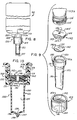
- FIG. 1 is a perspective view of a liquid dispensing system, constructed in accordance with and embodying the features of the present invention;
- FIG. 2 is an enlarged, exploded, perspective view of the actuator mechanism of the liquid dispensing system of FIG. 1;
- FIG. 3 is a further enlarged, fragmentary view in vertical section taken along the ling 3-3 in FIG. 1, and illustrating the actuator mechanism in its normal reset configuration;
- FIG. 4 is a view in horizontal section taken along the line 4-4 in FIG. 3;
- FIG. 5 is a top plan view of the plunger of the actuator mechanism;
- FIG. 6 is a side elevational view of the plunger of the actuator mechanism;
- FIG. 7 is a perspective view of the plunger of the actuator mechanism;
- FIG. 8 is a view of a liquid cartridge including a liquid container and a discharge assembly which are constructed in accordance with and embodying the features of the present invention;
- FIG. 9 is an exploded view of the discharge assembly illustrated in FIG. 8;
- FIG. 10 is an enlarged, fragmentary view in vertical section of the discharge assembly;
- FIG. 11 is a front elevational view of the nipple of the discharge assembly;
- FIG. 12 is a sectional view taken along the line 12-12 of FIG. 11;
- FIG. 13 is an enlarged fragmentary view of the nipple, illustrating details of its discharge outlet;
- FIG. 14 is a bottom view of the nipple of the discharge assembly;
- FIGS. 15-17 are simplified fragmentary views of the discharge assembly in vertical section illustrating successive stages of liquid discharge and recharge;
- FIG. 18 is a view in section of the housing of the liquid dispensing system illustrated in FIG. 1 showing the anti-bootleg device with the liquid cartridge illustrated in phantom, mounted on the housing;
- FIG. 19 is as top plan view of the housing with the anti-bootleg device removed;
- FIG. 20 is an enlarged, fragmentary view, in section, taken along the line 20-20 in FIG. 19;
- FIG. 21 is a top plan view of the anti-bootleg device of the housing;
- FIG. 22 is a bottom plan view of the anti-bootleg device illustrated in FIG. 21;
- FIG. 23 is a front elevational view of the anti-bootleg device illustrated in FIG. 21;
- FIG. 24 is a side elevational view of the anti-bootleg device illustrated in FIG. 21;
- FIG. 25 is a front elevational view of a liquid container of the liquid dispensing system illustrated in FIG. 1;
- FIG. 26 is a rear elevational view of the liquid container;
- FIG. 27 is a left side elevational view of the liquid container;
- FIG. 28 is a right side elevational view of the liquid container;
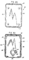
- FIG. 29 is a top plan view of the liquid container;
- FIG. 30 is a bottom plan view of the liquid container;
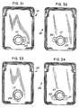
- FIGS. 31-34 are bottom plan views of liquid containers having alternative configurations for preventing unauthorized use; and
- FIGs. 35-38 are top plan views of anti-bootleg devices for use with the liquid containers shown in FIGS. 31-34, respectively.
- Referring to FIGS. 1-4, there is illustrated a liquid dispensing system, generally designated by the numeral 20, constructed in accordance with and embodying the features of the present invention. The
liquid dispensing system 20 comprises adispenser 25 adapted to be mounted on an associatedsupport surface 21, such as on awall 22 and, more particularly, in arecess 23 therein (see FIGS. 3 and 4), and a disposableliquid cartridge 26 which contains a supply of liquid and is removably mountable on thedispenser 25 for cooperation therewith to control the dispensing of liquid therefrom. The liquid may be liquid soap, alcohol, gel, suntan oil, or any material that flows. In accordance with one aspect of the invention, the liquid cartridge includes a discharge assembly which allows mounting of the cartridge on the dispenser without specific orientation therebetween. Moreover, the discharge assembly includes a filter which prevents contaminated air from entering the cartridge, which filter allows a more positive air flow condition than is provided by known liquid dispensing systems of the type which are vented through their outlet opening. In accordance with a further aspect of the invention, the liquid dispenser includes an anti-bootleg structure for preventing unauthorized cartridges from being used with the dispenser, the anti-bootleg structure including ananti-bootleg device 28 secured to the dispenser and a cooperatingsurface configuration 29 for the cartridge neck, as will be described. Preferably thecartridge 26 is inexpensively manufactured so as to be disposable. - More specifically, the
dispenser 25 includes ahousing 30, which is preferably of unitary, one-piece construction and may be formed of molded plastic. Thehousing 30 is similar to the housing disclosed in United States patent no. 4,673,109, which is assigned to Steiner Corporation. Thehousing 30 includes a flatrectangular base wall 31 and an upstanding rectangular mountingwall 32 integral with thebase wall 31 at the rear edge thereof and disposed substantially perpendicular thereto. The mountingwall 32 may havefastener holes 33 therethrough for receiving associated fasteners (not shown), securely to mount thehousing 30 on the associatedsupport surface 21. Thehousing 30 andcartridge 26 define mating edge surfaces providing a retaining system like that for the dispenser and cartridge illustrated in the referenced U.S. patent no. 4,673,109. To this end, integral with thebase wall 31 and extending upwardly therefrom along the front and side edges thereof, is a continuousperipheral flange 34, having a stepped downportion 34a on the front edge.Side flanges 35 are respectively integral with the side edges of the mountingwall 32 and project forwardly therefrom to join theperipheral flange 34. Respectively integral with theside flanges 35 at the forward or distal edges thereof, and projecting laterally inwardly therefrom substantially parallel to the mountingwall 32, are two retainingrails 36, each extending the entire length of the mountingwall 32 to thebase wall 31. - Briefly, referring to FIGS. 1 and 3, and also to FIGS. 25-28 of the drawings, the
cartridge 26 includes aliquid container 90 and aliquid discharge assembly 120 which is described in detail hereinbelow. Theliquid container 90 is a generally box-like container, which may be formed of a suitable plastic material. Preferably, thecontainer 90 is generally in the form of a rectangular parallelepiped having atop wall 92, abottom wall 93, afront wall 94, arear wall 95 and a pair ofopposed side walls 96. Thefront wall 94 and theside walls 96 are set back or recessed along their lower edges adjacent to their junction with thebottom wall 93 to define asupport shoulder 97. Thetop wall 92 projects rearwardly a slight distance beyond therear wall 95 to form an overhang which defines astop flange 98. Formed in the container 91 at the junctions of therear wall 95, respectively, with theside walls 96, are two elongatedlongitudinal grooves 100 which extend from the level of thestop flange 98 downwardly to thebottom wall 93. The lower portions of thegrooves 100 are cut away, as at 101, so as to definelugs 102 adjacent to the upper ends of thegrooves 100. The cartridge outer surfaces are all dimensioned so that when thecartridge 26 is in its use position on the dispenser the outer surfaces of the front wall and the side walls are, respectively, substantially coplanar with corresponding portions of the housing so as to present an attractive, smooth outward appearance. Also, the retaining system formed byrails 36 andgrooves 100 prevent forward tilting of the cartridge relative to the dispenser. - Referring again to FIGS. 1-4, integral with the
base wall 31 and with the mountingwall 32 and substantially perpendicular to each are a pair of laterally spaced-apart,upstanding support plates 37, respectively provided with laterally aligned bearingnotches 38 in the upper edges thereof (see FIG. 3). Formed in thebase wall 31 is an elongated, generally rectangular opening 39 (FIGS. 3 and 4) which extends laterally between thesupport plates 37, theopening 39 having a rearwardly extendingrectangular arm 39a and having an arcuate forward end. - Integral with the
housing 30 is areceptacle 40 having aperipheral wall 41 which lines the forward portion of theopening 39, theperipheral wall 41 having an arcuate front end and parallel side portions, which side portions are respectively parallel to thesupport plates 37 and are integral with the inner surfaces thereof at the front ends thereof. Theperipheral wall 41 projects above and below thebase wall 31 and is closed at its lower end by abottom wall 42 which is disposed substantially parallel to thebase wall 31. Thebottom wall 42 has acircular opening 43 therein adjacent to the forward end thereof, and a generally T-shapedslot 44 therethrough (FIG. 3) just rearwardly of thecircular opening 43. Respectively formed in the side portions of theperipheral wall 41 below thebase wall 31 are two laterally aligned circular pivot openings 45 (FIG. 18). - Integral with the rear ends of the side portions of the
peripheral wall 41 and projecting laterally inwardly therefrom are tworear flanges 46, each having a notch or recess 47 at the lower end thereof. Astop web 48 laterally spans the side portions of theperipheral wall 41, extending a slight distance above and below thebase wall 31, theweb 48 having arectangular notch 48a in the lower edge thereof and a forwardly directed ledge portion 48b near its upper end. Arectangular stop web 49 is formed integrally with and extends upwardly from thebase wall 31.Web 49 is disposed substantially parallel to thestop web 48 and laterally spans theperipheral wall 41 near its arcuate front end. The upper edge of the stop web and the upper surface of the ledge portion 48b lie substantially in a common horizonal plane.Web 49 has a rearwardly directedboss 49a which is semi-cylindrical in shape and extends substantially the width of theweb 49. - The
dispenser 25 also includes anactuator assembly 50 which is removably mounted in thehousing 30. Theactuator assembly 50 includes ahandle 51 comprising arectangular plate 52 provided at its upper end with aninclined portion 53, which is in turn provided at its distal end with laterally outwardly extending cylindrical pivot lugs 54. The pivot lugs 54 are respectively received in the bearingnotches 38 for pivotally supporting thehandle 51 which extends through opening 39 in the housing bottom, for movement between actuating and retracted positions. Theplate 52 has a width slightly less than the width of theopening 39, so that thebase wall 31 at the rear end of theopening 39 and therear flanges 46 of thereceptacle 40 provide rear and front stops to limit the pivotal movement of thehandle 51. Formed in the front surface of theplate 52 is arectangular recess 55, near the lower end of which is formed arectangular slot 56 which extends through the thickness of theplate 52 midway between the side edges thereof and in position so as to be disposed below thebase wall 31 when thehandle 51 is disposed in its mounted condition in thehousing 30. - The
actuator assembly 50 also includes abias unit 60 which comprises alatch member 61 and abias leaf 70. Thelatch member 61 is generally in the form of a clevis having a pair of parallel, spaced-apart arms 62, respectively provided with angled feet 63, at the lower ends thereof. The feet 63 are respectively provided with laterally outwardly extending circular cylindrical pivot lugs 64, each having a substantially squarekey socket 65 formed in the outer end thereof, which may extend laterally completely therethrough. - Each of the feet 63 is also provided on its inner surface with a bearing
boss 66. Thearms 62 are interconnected at their upper ends by abight portion 67 provided with a forwardly extendinglatch flange 68 having a partfrustoconical cam surface 69 thereon which locks the cartridge in place on the dispenser. Thelatch member 61 is dimensioned to fit within thereceptacle 40 with thearms 62 respectively disposed along the inner surfaces of the side portions of theperipheral wall 41. For mounting, thearms 62 are resiliently deflected together to permit the pivot lugs 64 to clear the inner surfaces of theperipheral wall 41, and then thelatch member 61 is lowered into thereceptacle 40 until the pivot lugs 64 respectively snap out into the pivot openings 45 (FIG. 18 ), pivotally to mount thelatch member 61. The length of thearms 62 is such that when thelatch member 61 is in this mounted condition, thelatch flange 68 is disposed a predetermined distance above the upper end of thereceptacle 40. - The
bias leaf 70 comprises a thin, flat, rectangular band which is formed of a suitable flexible and resilient material, such as a suitable plastics material. One end of thebias leaf 70 is fixedly secured to the rear surface of thebight portion 67 of thelatch member 61 by suitable means (not shown). Thebias leaf 70 is fabricated with predetermined curvature therein, and is provided with acurved tip 72 at its distal end which has arectangular slot 73 therethrough. There is also provided a key 75 having alug 76 thereon which is disposed for mating engagement in one of thekey sockets 65 to effect manual rotation of thelatch member 61 about the axis of the pivot lugs 64 for releasing the cartridge when spent, allowing replacement with a full cartridge. - The
actuator assembly 50 also includes aplunger 80, which is generally in the shape of a rectangular, box-like, open-top frame. More particularly, referring to FIGS. 2-7, theplunger 80 includes a pair of parallelrectangular side walls 81 interconnected, respectively, at the forward and rearward ends thereof by afront bearing wall 82 and arear wall 83. - The
front bearing wall 82 curves forwardly and downwardly from its upper edge to a point of maximum forward extension definingcam surface 82a which is approximately one third the distance from its upper edge to its lower edge, the frontbearing wall portion 82b extending linearly downwardly and rearwardly from its point of maximum forward extension to its bottom edge. Thus, thefront bearing wall 82 defines a generallyarcuate cam surface 82a which is offset upwardly of the horizontal center line of theplunger 80 and followingsurface 82b. - The
arcuate cam surface 82a is aligned with and in opposing relation to theboss portion 49a onweb 49. Therear wall 83 is provided with a forwardly extendingpin 85 which is received inslot 73 ofbias leaf 70. Integral with the outer or rear surface of therear wall 83 is a rearwardly extendingrectangular positioning lug 86 which is received inslot 56 in thehandle 51. Theside walls 81 are interconnected at the lower edges thereof, intermediate the front and rear ends thereof by arectangular bottom web 87. Theplunger 80 is dimensioned so that it can fit between the notches 47 of the receptaclerear flanges 46, through thenotch 48a in thestop web 48 and between the bearingbosses 66 oflatch member 61 for reciprocating siding movement forwardly and rearwardly along thebottom wall 42 of thereceptacle 40 between pumping and release positions in response to operation and release of thehandle 51. - The parts of the
actuator assembly 50, viz., thehandle 51, thebias unit 60 and theplunger 80, can be quickly and easily assembled with thehousing 30 without the use of tools and, when thus assembled, will cooperate with each other and with thehousing 30 to retain theactuator assembly 50 in thehousing 30 and prevent accidental removal thereof. The manner in which theactuator assembly 50 is assembled in the housing is described in detail in the referenced U.S. patent no. 4,673,109. - Referring to FIGS. 1, 3 and 8-10, the
liquid cartridge 26 includes aliquid container 90 and adischarge assembly 120. Integral with theliquid container 90 at the distal end thereof is a cylindrical nozzle orneck 113 which projects downwardly from the bottom wall and which includes athin wall portion 113a which defines an outlet opening for thecontainer 90. Theneck portion 113 of theliquid container 90 is externally threaded as at 114 and has anend surface 115, as seen in FIG. 8. Thedischarge assembly 120 includes an elongated, generallycircular nipple 121 and a check valve assembly 122. Thedischarge assembly 120 is mounted on the threaded neck portion of the liquid container and maintained thereon by a retainingcap 123. - Referring to FIGS 9-14, the
nipple 121 is formed of a suitable flexible resilient material, such as rubber. Thenipple 121 has a main body portion defined by acylindrical side wall 130 which is provided at its proximal end with a radially outwardly extendingflange 131 and an annularupstanding wall 132 defining aninlet chamber 133 for the discharge assembly. The hollow main body portion defines adischarge chamber 135 for the discharge assembly. Theside wall 130 is provided at its distal end with a pair of radially inwardly slopingconcave walls 136 which cooperate to form a flat, narrow duckbill-shapedtip 137 at the distal end of the nipple, closing thedischarge chamber 135. Formed in thetip 137 and extending longitudinally thereof, substantially diametrically of thenipple 130, is anelongated slot 138 which in length is approximately one-half the diameter of the nipple. The upper edge of theslot 138 terminates in an elongated discharge slit 139, which is normally held closed by the resilient biasednipple 130. Also, theslit 139 extends along only a portion, approximately one-third, of the length of the duck-bill tip 137. Non-slittedtop portions 137a on each side of theslit 139 assist in maintaining theslit 139 closed in the absence of release pressure in thenipple discharge chamber 135. Theslit 139 is recessed relative to the distal tip of the nipple by an amount corresponding to the depth of theslot 138. The ratio of the length "L" of the main body portion and tip of the nipple to the average diameter "D" is about 3 to 1. This extended length of thenipple 121 and the improved tip construction together with the profile of the plungerfrong bearing wall 82 enable the cartridge to be installed on the dispenser without orientation of the nipple relative to the plunger. That is, it is not essential that the nipple be oriented relative to the plunger such that it is compressed in a direction perpendicular to the discharge slit 139. - As shown in FIGS. 9-10, the check valve assembly 122 includes a
valve diaphragm disc 140 and afilter member 142. Thevalve diaphragm 140 is a thin, flat circular membrane or diaphragm dimensioned to fit within the inlet chamber or well 133 defined by the upstandingannular wall 132 of thenipple 121 with its lower peripheral edge 140a supported by a ledge or shoulder portion 131a defined by the inner upper surface offlange 131. The diaphragm is made of a suitable flexible material which is impermeable to liquid. The diaphragm has a straight-line check valve slit 141 formed therein centrally thereof and extending substantially diametrically. - The
filter member 142 has a cylindricalmain body portion 143 with an annular flange 144 extending outward radially at its upper surface 145. Thefilter member 142 has anaxial bore 146 formed therethrough centrally thereof from its upper surface 145 to itslower surface 147. The outer diameter of themain body portion 143 at itsdistal end surface 147 corresponds to the outer diameter of the valve diaphragm, which diameters are slightly less than the inner diameter of the well 133 defined by theannular wall 132 of the nipple. The outer diameter of the top surface 145 including the flange 144 is approximately the same as the outer diameter ofannular wall portion 132 ofnipple 121. Thefilter member 142 may be made from any suitable material which permits air to pass therethrough but which does not permit liquid to flow therethrough, such as a hydrophobic cell structured thermoplastic. Material particularly suitable for this purpose is commercially available. Representative thermoplastics are nylon, polyesters, polypropylene and teflon, polyurethane, ABS and the like, produced for instance by Filtertek, Inc. of Hebron, Illinois. The filter element is a molded porous plastic material having a pore size in the range of about 0.2 microns to about 40 microns. - In use, the
valve diaphragm 140 is positioned in the well 133 with its peripheral edge 140a supported on the ledge portion 131a. Thefilter member 142 is positioned in the well 133 with itslower surface 147 engaging the upper surface of the valve diaphragm over substantially its entire extent and with the under surface of its flange engaging the top edge surface of theannular wall 132. Thus, when the discharge assembly is assembled with a cartridge, thefilter member 142 substantially fills the entire inlet chamber or well 133 of the nipple between the outlet of the container and thevalve diaphragm 140. Moreover, because the filter presents a large surface area to the outlet of theliquid container 90 and is located in contact with the liquid, the filter material is continually wetted by the liquid and thus will not become clogged by dried or hardened liquid. Theaperture 146 through thefilter member 142 is aligned with the valve slit 141 in the valve diaphragm by virtue of its being located axially of the filter member, and defines a passageway for liquid to the valve disc. - The retaining
cap 123 is in the form of a cylindrical collar which has acentral aperture 151 of a size through which the main body portion of thenipple 121 may grass. The retaining cap hasinternal threads 152 between its upper edge surface 153 and itslower edge surface 154 which are dimensioned loosely to engage the external threads 114 on theliquid container neck 113 and with the liquid containerlower edge 115 engaging the upper surface 145 of thefilter member 142. The retainingcap 123 serves to removably mount thedischarge assembly 120 on the neck of the container 112. Because the retainingring 123 removably secures the discharge assembly to thecontainer 90, it is possible to
recover discharge assemblies from spent cartridges, if desired. - The discharge assembly controls the flow of liquid between the outlet opening of the
container 90 and the inlet opening orinlet chamber 133 of thenipple 121. An air path is thereby established, as best seen by the arrows in FIG. 10, between outside thecontainer 90 and the inside thereof, which air path flows between theneck 13 of theliquid container 90 and the upper edge 153 of thecylindrical collar 123 through and along thethreads 114 and 152 and thereafter through thespace 160 and through thefilter member 142 into theliquid container 90. - In use, when the
discharge assembly 30 has been assembled and mounted on the container as described above, the check valve assembly 122 is disposed for controlling the flow of liquid between the outlet opening of thecontainer 90 and the inlet opening orinlet chamber 133 of thenipple 121. - Referring to FIGS. 1, 2 and 18, in mounting the
cartridge 26 on thedispenser 25, it is placed over thedispenser 25 with theneck 113 disposed downwardly. Thecartridge 26 is slid down along the mountingwall 32 of thehousing 30, with the retaining rails 36 being respectively recessed in thelongitudinal grooves 100. As the cartridge is lowered into its use position, thenipple 121 extends downwardly into thereceptacle 40 betweenstop webs circular opening 43 in thebottom wall 42. Thelatch flange 68 oflatch member 61 projects forwardly beyondstop web 48, engaging the top surface edge 153 of thecap 123 so as to obstruct the path of the neck 112, latching the cartridge in place. Thelower edge 154 of the retainingcap 123 rests onledge 48a and on the upper edge 49b ofweb 49, locating themain body portion 130 of thenipple 121 between theforward cam surface 82a of theplunger 80 and therearwardly extending boss 49a on thefront web 49. - Referring to FIGS. 3, 8 and 15-17, the operation of the
discharge assembly 120 will be explained. With the continual feed of air into theliquid container 90, the atmospheric pressure plus the weight of the liquid in the container on thediaphragm disc 140 near theslit 141 therein will force the check valve slit 141 open, allowing liquid to flow through the check valve slit opening into thedischarge chamber 135 in thenipple 121. This flow will continue until thedischarge chamber 135 is filled, at which time the pressure on the opposite sides of thevalve disc 140 will be equalized, thereby allowing the check valve slit 141 to close in an equilibrium condition, as illustrated in FIG. 15. Thenipple 121 is so constructed that in this normal equilibrium condition, the natural resilient bias of thenipple 121 will hold the discharge slit 139 closed against the weight of the charge of liquid contained in thedischarge chamber 135. - In order to dispense a charge of liquid, a user places his palm under the
nipple 121 and pulls the handle 51 (FIG. 3) forwardly towards its actuating position with his fingers. This drives theplunger 80 forwardly of the housing to its pumping position against the force ofbias member 70, and into engagement with thenipple 121, compressing it, as shown in FIG. 16, between thecam surface 82a and theboss 49a onforward wall 49, ejecting the charge of liquid therefrom through thedischarge outlet 137 of thenipple 121. Initially, the tip of thecam surface 82a engages the nipple main body portion near its upper end, compressing the nipple near its upper end. With continued forward linear movement of theplunger 80, the upper end of the nipple will be pinched closed by thecam suface 82a while the liquid contained in the nipple is forced out as followingsurface 82b of the plunger compresses the nipple in a downward motion as it is being engaged by followingsurface 82b. - The compression of
cylindrical wall 130 of thenipple 121 raises the pressure in thedischarge chamber 135, so that it holds the check valve slit 141 of thevalve diaphragm 140 closed and against the under side offilter member 142 to force the ejection of a charge of liquid from thedischarge chamber 135. Because the center of thecheck valve disc 140 is held against thefilter member 142 during the discharge operation, no change in the pressure in the liquid container occurs at this time. When thehandle 51 is released, theplunger 80 will return to its normal rest position under the urging of thebias member 70, and thecompressed wall 132 of thenipple 121 will return to its normal expanded condition, see FIG. 17, as a result of the natural resilience of thenipple 121. This reexpansion of thenipple 121 will lower the pressure therein to a pressure below that in thecontainer 90, so as to allow the check valve slit 141 to open under the force of atmospheric pressure and the weight of the liquid in the container. Hence, a new charge of liquid is drawn from the container 90 (thereby creating lower pressure in container 90) throughaperture 146 in thefilter member 142 and thecheck valve opening 141 and thediaphragm disc 140 into thedischarge chamber 135 of thenipple 121. The rate at which the liquid flows into thenipple 121, and particularly into thedischarge chamber 135, is controlled to some extent by the pressure in theliquid container 90. The pressure is equalized to normal atmospheric pressure by means of the air path established between the inside of theliquid container 90 and the atmosphere (which path is shown by the arrows in FIG. 10) and flows through thefilter member 142 and theinlet chamber 133. Particularly, the air flows downwardly past the upper edge 153 of the retainingcap 123 through and around themating threads 114, 152 and into the annular space beneath the threads and hence through thefilter member 142 to the liquid container outlet, and into thecontainer 90. This mechanism permits air to flow into theliquid container 90 while retaining the liquid therein. This construction facilitates rapid discharge and charge of the discrete quantities of liquid from thenipple 121 and is an improvement over the previous constructions heretofore mentioned. - Thus, the liquid dispensing system provided in accordance with the present invention includes a discharge assembly and an actuating mechanism therefor which allows mounting of the cartridge on the dispenser without specific orientation of the nipple of the discharge assembly relative to the plunger of the actuating mechanism. Moreover, the discharge mechanism includes a filter element which is constructed and arranged to both define a portion of an air passageway for venting the liquid container through its outlet opening and for providing a passageway for liquid from the container to the discharge nipple, the filter element allowing a more positive air flow condition than is provided by known liquid dispensing systems of the type employing containers vented through their outlet opening.
- Referring to FIGS. 3, 18, 19 and 21-30 in accordance with another aspect of the invention, the
dispenser 25 includes ananti-bootleg structure 28 includinganti-bootleg device 160 for preventing unauthorized cartridges from being used in thedispenser 25. Theanti-bootleg device 160, best shown in FIGS. 21-24, comprises a flat plate-like member 161 generally rectangular in shape and having acentral opening 162 therethrough of an irregular shape, complementary with irregular shapedneck portion 164 of the associatedcontainer 26 shown in FIGS. 25-30. Theplate member 161 has aforward edge 165, a rearward edge 166, aleft side edge 167 and aright side edge 168. The irregular shapedopening 162 includes a generally circularcentral aperture 162a with a generally rectangular-shapedextension 162b extending toward theleft side edge 167 of the plate and an arcuate segment 162c extending toward theforward edge 165 of the plate member. - The
plate member 161 is mounted on the housing 30 (FIG. 18) overlying the well 40 which receives thedischarge assembly 120 of thecartridge 26, with the neck of thecartridge 26 extending through the irregular shapedaperture 162 of theplate member 161. It is apparent that only cartridges which have a neck portion configured to pass through theirregular opening 162 in theanti-bootleg device 160 can seat on thedispenser 25 in such a way as to permit thedischarge assembly 120 of thecartridge 26 to be operated by actuator mechanism of the dispenser. - For the purpose of mounting the
anti-bootleg device 160 on the housing, thedevice 160 has four projections or lugs 171-174 which depend from lower surface 175 of theplate 161, one located near each of the four corners of the plate. Thehousing 30 has four supports or posts 176-179 which are formed integrally with and extend upwardly from thebase 42 of thehousing 30. Two of the posts 176-177 are located on the left side of the well and the other two posts 178-179 are located on the right side of the well 40. All four posts extend to a height above the upper edge of the well 40 to locate theanti-bootleg device 160 in overlying relation with the well and slightly above the upper edge surface of the well. The lugs 171-174 are split at 180 and are dimensioned to be received inapertures 170 through therespective posts inner shoulder 181. The lugs may be retained in theapertures 170 by a snap fit, ultrasonic welding or other means to permanently secure theplate 161 to the housing. - As illustrated in FIGS. 22 and 23, the spacing between
lugs forward edge 165 of theplate 161 is less than the spacing betweenlugs posts posts plate 161 when it is installed on the housing. - Referring now to FIGS. 25-30, the
liquid container 90 is particularly adapted to be received by thedispenser 25 including theanti-bootleg device 160. Theneck 113 of thecontainer 90 has a generallycylindrical portion 184 of a diameter corresponding to the diameter of theaperture 162a in theplate 161 and with a generallyrectangular boss 185 and anarcuate boss 186 which are complementary toaperture extension portions 162b and 162c, respectively, of theaperture 162 in theanti-bootleg plate 161. - Various combinations of rectangular and arcuate aperture portions can be used to define many unique irregular shapes for
anti-bootleg device 160 and cartridges for use exclusively therewith. Moreover, only theanti-bootleg device 160 need be different, permitting manufacture of a "generic" dispenser unit, adapted by application thereto of a given anti-bootleg device to receive a given cartridge. For example, referring now to Figs. 31-34, there are illustrated four cartridges 191-194 each having a different irregular-shaped neck portion for use with a dispenser having, respectively, one of the four anti-bootleg devices 195-198 illustrated in FIGS. 35-38. - Referring to FIGS. 31 and 35,
device 195 has an irregular-shapedopening 201 having two rectangular extension portions 201a and 201b which extend toward itsleft side edge 167 of theplate member 161. Portion 201a, which is the same shape and the same location asportion 162b (FIG. 21), is longer than portion 201b. Correspondingly, theneck 113 ofcontainer 191 has complementary shapedrectangular bosses neck 113 and dimensioned to pass through theirregular opening 201 in thedevice 195. - Referring to FIGS. 32 and 36,
device 196 has anirregular opening 204 having two generallyrectangular extension portions 204a and 204b, which are the same shape as portion 101a and extend, respectively, towards itsleft side edge 167 and itsright side edge 168 rearward of the center line of theplate 161. Theneck 113 ofcontainer 192 has complementary shapedbosses neck 113 and dimensioned to pass through theirregular opening 204 in thedevice 196. - Referring to FIGS. 33 and 37,
device 197 has an irregular shapedopening 207 having anarcuate extension portion 207a which is the same shape and at the same location as portion 162c of device 160 (FIG. 21) and which extends towards itsforward edge 165.Associated container 193 has acomplementary boss 208 on itsneck 113 which is disposed to pass through the irregular opening in thedevice 197. - Referring to FIGS. 34 and 38,
device 198 has an irregular-shapedopening 209 having two generallyrectangular extension portions 209a and 209b which are the same shape as portion 201b (FIG. 35) and extend, respectively, toward theleft side edge 167 and theright side edge 168, but forward of the center line of theplate 161.Corresponding container 194 hascomplementary bosses 211 and 212 on itsneck portion 113 which are disposed to pass through theirregular opening 209 in thedevice 198. - It is seen therefore that there has been provided a liquid dispensing system in which a
common dispenser 25 has permanently mounted to it a selected one of a plurality of anti-bootleg devices, overlying the actuator mechanism and upon which an associated cartridge must be mounted. The anti-bootleg device has a particularly chosen irregular-shaped opening which will preclude the use of any cartridge except a cartridge having a complementary shaped neck portion. The user of unauthorized cartridges in dispensers having the anti-bootleg device of the present invention is prevented because the anti-bootleg device precludes proper seating of the dispensing mechanism of such unauthorized cartridge on the actuator mechanism, whereby the actuator cannot operate the dispenser mechanism, thereby rendering the liquid dispenser inoperable.
Claims (15)
- A liquid dispenser (25) comprising, an unvented liquid container (90) having only an outlet opening (113), a discharge assembly (120) in liquid communication with said liquid container outlet opening (113), said discharge assembly (120) including discharge means defining a discharge chamber (135) for accommodating a charge of liquid and an inlet chamber (133) for introducing liquid to said discharge chamber (135), and check valve means (122) in said inlet chamber for regulating the flow of liquid from said container (90) to said discharge chamber (135) said check valve means including a valve member (140) and an element (142) mounted in and substantially filling said inlet chamber (133) between said valve member (140) and said liquid container outlet opening (113), said element (142) establishing an air passage to introduce air into said liquid container upon withdrawal of liquid from said container (90), said element (142) having an opening (146) therethrough defining a passageway for liquid from said container outlet opening (113) to said valve member (140) for introduction into said discharge chamber, characterised in that said element (142) is a semipermeable filter element of a material which is permeable to air and impermeable to liquid.
- A liquid dispenser according to claim 1, characterised in that an air passage connects said filter element (142) to the outside of said liquid container.
- A liquid dispenser according to claim 1, characterised by retaining means (114, 152) holding said discharge assembly (120) in position with respect to said liquid container (90) and providing an air passage to said filter element (142).
- A liquid dispenser according to any of the preceding claims, characterised in that said filter element (142) is generally cylindrical in shape and has an outer diameter corresponding to the inner diameter of said cartridge outlet opening (113); said opening (146) through said filter element (142) being located centrally thereof.
- A liquid dispenser according to any of the preceding claims, characterised in that said filter element (142) is a molded porous plastic material having a pore size in the range of about 0.2 microns to about 40 microns.
- A liquid dispenser according to any of the preceding claims, characterised in that said filter element (142) is made of a hydrophobic microporous polypropylene.
- A liquid dispenser according to any of the preceding claims, characterised in that said discharge assembly (120) includes an elongated flexible nipple (121) generally cylindrical in shape and having a normal expanded condition defining said discharge chamber (135) and wherein the axial length (L) of said discharge chamber is approximately three times its diameter (D).
- A liquid dispenser according to any of claims 1 to 6, characterised in that said discharge assembly (120) comprises an elongated flexible resilient nipple (121) having a normal expanded condition defining said discharge chamber (135), said nipple (121) having first and second ends with said inlet chamber at said first end thereof and being provided at said second end thereof with a normally closed discharged slit (139), and retaining means (114,152) mounting said nipple (121) on the container (90) with said inlet chamber (133) disposed in registry with the container outlet opening (113), said nipple (121) being laterally compressible in a direction substantially perpendicular to its longitudinal axis, movement of said nipple (121) to the compressed condition thereof raising the pressure in said discharge chamber (135) for closing said check valve means and ejecting liquid from said discharge slit (139), movement of said nipple (121) back to the expanded condition thereof lowering the pressure in said discharge chamber (135) for closing said discharge slit (139) and opening said check valve means to draw a new charge of liquid into said discharge chamber (135) passage of air through said filter element (142) rapidly reestablishing air pressure in said liquid container (90) permitting rapid refill of said discharge chamber (135) with liquid and rapid activation of said discharge assembly.
- A liquid dispenser according to claim 8, characterised in that said valve member includes a flat membrane (140) extending across said inlet opening and having a valve slit (141) formed therein centrally thereof, said filter element (142) overlying said membrane (140) with its opening (146) therein centrally thereof and disposed in registry with said valve slit (141).
- A liquid dispenser according to claim 8 or 9, characterised in that said nipple has an annular upstanding wall (132) at said first end defining said inlet chamber and a shoulder (131a) at the base of said wall, said membrane (140) having its peripheral edge supported on said shoulder (131a) and said filter element (142) being contained substantially within said inlet chamber (133).
- A liquid dispenser according to claim 1, characterised in that the liquid container and said discharge assembly (120) comprise a replaceable liquid cartridge removably mountable on a housing (30) of said dispenser, the liquid dispenser further comprising an actuating mechanism (50) mounted in said housing, and anti-bootleg means (160), mounted in said housing in overlying relationship with said actuating mechanism, said anti-bootleg means having an opening (162) therethrough of a predetermined configuration, said liquid container (26) having a neck portion (164) complementary in shape to said opening (162) through said anti-bootleg means (160) permitting said neck portion (164) to pass through said anti-bootleg means to mount said cartridge on said housing with said discharge assembly (120) disposed in operative relationship with said actuating mechanism (50) for dispensing liquid from said liquid container, and said anti-bootleg means preventing cartridges without a neck portion of said predetermined configuration from being mounted on said housing (30) with their discharge assembly disposed in operative relationship with said actuating mechanism (50).
- A liquid dispenser according to claim 11, characterised in that said anti-bootleg means (160) is permanently secured to said housing.
- A liquid dispenser according to claim 11 or 12, characterised in that said anti-bootleg means (160) comprises a flat plate-like member (161) and mounting means (171-174) mounting said plate-like member (161) on said housing (30) in a horizontal orientation, said discharge assembly (120) being passed through said opening (162) through said plate-like member (161) during mounting of said cartridge on said dispenser.
- A liquid dispenser according to claim 13, characterised in that said mounting means comprises a plurality of projections (171-174) on said plate-like member and a corresponding plurality of recesses (170) in said housing receiving said projections.
- A liquid dispenser according to claim 13 or 14, characterised in that said plate-like member (161) has a generally circular opening therethrough and has at least one cutout portion along a portion of the circumference defining an irregular configuration for said opening and wherein said configured neck portion of said container is generally cylindrical in shape and has a boss corresponding in shape to said cutout portion.
Priority Applications (1)
| Application Number | Priority Date | Filing Date | Title |
|---|---|---|---|
| AT9191303793T ATE105163T1 (en) | 1990-05-01 | 1991-04-26 | FLUID DISPENSER WITH DISPENSING DEVICE FOR GENERATION OF AN INTAKE AIR FLOW. |
Applications Claiming Priority (2)
| Application Number | Priority Date | Filing Date | Title |
|---|---|---|---|
| US517244 | 1990-05-01 | ||
| US07/517,244 US5082150A (en) | 1990-05-01 | 1990-05-01 | Liquid dispensing system including a discharge assembly providing a positive air flow condition |
Publications (2)
| Publication Number | Publication Date |
|---|---|
| EP0455431A1 EP0455431A1 (en) | 1991-11-06 |
| EP0455431B1 true EP0455431B1 (en) | 1994-05-04 |
Family
ID=24058993
Family Applications (1)
| Application Number | Title | Priority Date | Filing Date |
|---|---|---|---|
| EP91303793A Expired - Lifetime EP0455431B1 (en) | 1990-05-01 | 1991-04-26 | Liquid dispensing system including a discharge assembly providing a positive air flow condition |
Country Status (6)
| Country | Link |
|---|---|
| US (1) | US5082150A (en) |
| EP (1) | EP0455431B1 (en) |
| JP (1) | JPH04227219A (en) |
| AT (1) | ATE105163T1 (en) |
| CA (1) | CA2041120A1 (en) |
| DE (1) | DE69101873T2 (en) |
Cited By (5)
| Publication number | Priority date | Publication date | Assignee | Title |
|---|---|---|---|---|
| US7066356B2 (en) | 2002-08-15 | 2006-06-27 | Ecolab Inc. | Foam soap dispenser for push operation |
| US9265383B2 (en) | 2012-02-08 | 2016-02-23 | Simplehuman, Llc | Liquid dispensing units |
| USD770798S1 (en) | 2015-02-25 | 2016-11-08 | Simplehuman, Llc | Soap pump |
| USD773848S1 (en) | 2015-03-06 | 2016-12-13 | Simplehuman, Llc | Liquid dispenser cartridge |
| USD785970S1 (en) | 2016-01-25 | 2017-05-09 | Simplehuman, Llc | Soap pump head |
Families Citing this family (70)
| Publication number | Priority date | Publication date | Assignee | Title |
|---|---|---|---|---|
| US5312017A (en) * | 1991-08-30 | 1994-05-17 | The Coca-Cola Company | Product identification system for beverage dispenser |
| US6092695A (en) | 1992-05-11 | 2000-07-25 | Cytologix Corporation | Interchangeable liquid dispensing cartridge pump |
| US5328059A (en) * | 1992-07-01 | 1994-07-12 | Campbell Gary J | Sealed bottle water system |
| US5450982A (en) * | 1993-02-18 | 1995-09-19 | Van Den Oever; Menno H. | Filter change mechanism |
| GB9310481D0 (en) * | 1993-05-21 | 1993-07-07 | Sprintvest Corp Nv | Dispensing appratus |
| US5439144A (en) * | 1993-12-27 | 1995-08-08 | Steiner Company, Inc. | Liquid soap dispensing system |
| US5752629A (en) * | 1996-04-12 | 1998-05-19 | The Procter & Gamble Company | Passive venting for pump dispensing device |
| US5927567A (en) | 1996-11-12 | 1999-07-27 | Owens-Illinois Closure Inc. | Dispensing closure and method of making |
| US5878919A (en) * | 1997-08-20 | 1999-03-09 | Heggeland; Bruce E. | Fluid dispensing mechanism |
| US5988456A (en) * | 1998-01-16 | 1999-11-23 | Laible; Rodney | Closed loop dispensing system |
| US6142345A (en) * | 1998-01-16 | 2000-11-07 | Laible; Rodney | Closed loop dispensing system |
| US6015068A (en) * | 1998-02-04 | 2000-01-18 | Now Technologies, Inc. | Liquid chemical dispensing system with a key code ring for connecting the proper chemical to the proper attachment |
| US6073812A (en) * | 1999-01-25 | 2000-06-13 | Steris Inc. | Filtered venting system for liquid containers which are susceptible to contamination from external bioburden |
| US6321943B1 (en) | 1999-10-09 | 2001-11-27 | Gent-I-Kleen Products, Inc. | Soap dispenser for soap of different viscosity |
| EP1118300A1 (en) * | 2000-01-19 | 2001-07-25 | Cws International Ag | Soap dispenser |
| JP4580524B2 (en) * | 2000-09-12 | 2010-11-17 | 株式会社日本点眼薬研究所 | Discharge container with filter |
| JP4749572B2 (en) * | 2001-03-13 | 2011-08-17 | 大成化工株式会社 | Dispensing container plug structure |
| US6360595B1 (en) * | 2001-03-16 | 2002-03-26 | Ethicon Endo-Surgery, Inc. | Liquid measuring device and method of using |
| GB0206176D0 (en) * | 2002-03-15 | 2002-05-01 | Rieke Packaging Systems Ltd | Dispensers |
| US6814262B1 (en) * | 2002-06-21 | 2004-11-09 | Server Products | Disposable pump and drive mechanism for dispensing a liquid food product |
| US9518899B2 (en) * | 2003-08-11 | 2016-12-13 | Sakura Finetek U.S.A., Inc. | Automated reagent dispensing system and method of operation |
| US7744817B2 (en) * | 2003-08-11 | 2010-06-29 | Sakura Finetek U.S.A., Inc. | Manifold assembly |
| US7767152B2 (en) * | 2003-08-11 | 2010-08-03 | Sakura Finetek U.S.A., Inc. | Reagent container and slide reaction retaining tray, and method of operation |
| CA2477584C (en) | 2004-08-12 | 2011-07-26 | Hygiene-Technik Inc. | Disposable dispenser |
| CA2505812C (en) * | 2004-08-12 | 2013-04-09 | Gotohti.Com Inc. | Cantilevered spring |
| US7270250B2 (en) | 2004-08-30 | 2007-09-18 | Hygiene-Tecknik Inc. | Disposable dispenser |
| US20070138208A1 (en) * | 2005-12-16 | 2007-06-21 | 3M Innovative Properties Company | Dispenser |
| US8459509B2 (en) | 2006-05-25 | 2013-06-11 | Sakura Finetek U.S.A., Inc. | Fluid dispensing apparatus |
| US20080105580A1 (en) * | 2006-11-02 | 2008-05-08 | Tyco Healthcare Group Lp | Applicator Tip |
| EP2142441B1 (en) * | 2007-04-23 | 2013-03-06 | 3M Innovative Properties Company | Dispenser tip filter assembly |
| US20090014470A1 (en) * | 2007-07-11 | 2009-01-15 | Yung Hsing Lin | Liquid dispensing device |
| US20090114682A1 (en) * | 2007-11-01 | 2009-05-07 | Gittleman Neal B | Easy Access Dispenser |
| WO2010036844A1 (en) * | 2008-09-28 | 2010-04-01 | Langenbeck Keith A | Electrode cell design for use in electrocoagulation fluid treatment |
| US8397918B2 (en) * | 2008-09-28 | 2013-03-19 | Keith A. Langenbeck | Multiple flat disc type pump and hydrocyclone |
| CN102209630B (en) | 2008-10-10 | 2014-12-03 | 丹尼尔·皮 | Device with co-extruded body and flexible inner bladder and related apparatus and method |
| DE102009015303B4 (en) * | 2009-03-19 | 2012-10-31 | Ing. Erich Pfeiffer Gmbh | Device for applying a cosmetic powder on a sponge |
| US8083107B2 (en) * | 2009-04-09 | 2011-12-27 | Rodney Laible | Closed loop dispensing system with mechanical venting means |
| AT509748B1 (en) * | 2010-04-23 | 2012-11-15 | Hagleitner Hans Georg | REFILL UNIT WITH A CONTAINER |
| US8752732B2 (en) * | 2011-02-01 | 2014-06-17 | Sakura Finetek U.S.A., Inc. | Fluid dispensing system |
| ES2882776T3 (en) * | 2011-03-04 | 2021-12-02 | Simplehuman Llc | Soap dispenser units with non-drip valve |
| USD659452S1 (en) | 2011-03-04 | 2012-05-15 | Simplehuman, Llc | Soap pump |
| US8932543B2 (en) | 2011-09-21 | 2015-01-13 | Sakura Finetek U.S.A., Inc. | Automated staining system and reaction chamber |
| US8580568B2 (en) | 2011-09-21 | 2013-11-12 | Sakura Finetek U.S.A., Inc. | Traceability for automated staining system |
| US20130200109A1 (en) * | 2012-02-06 | 2013-08-08 | Frank Yang | Foaming soap dispensers and methods |
| USD674636S1 (en) | 2012-03-09 | 2013-01-22 | Simplehuman, Llc | Soap pump |
| USD693597S1 (en) | 2012-03-09 | 2013-11-19 | Simplehuman, Llc | Soap pump |
| US8708203B2 (en) | 2012-05-07 | 2014-04-29 | Rl Innovations, Llc | Screw-on throat plug assembly |
| EP2662138A1 (en) * | 2012-05-08 | 2013-11-13 | Roche Diagniostics GmbH | Microfluidic dispenser, cartridge and analysis system for analyzing a biological sample |
| US8550131B1 (en) | 2013-01-02 | 2013-10-08 | Liquid Squeeze, LLC | Liquid dispensing device, system and method |
| USD699475S1 (en) | 2013-02-28 | 2014-02-18 | Simplehuman, Llc | Soap pump |
| US20150014363A1 (en) * | 2013-07-12 | 2015-01-15 | Gojo Industries, Inc. | Air-vented liquid dispensers and refill units therefor |
| CA2923425A1 (en) * | 2013-09-13 | 2015-03-19 | Gojo Industries, Inc. | Dispensers for non-collapsing containers and venting pumps |
| US9648992B2 (en) | 2013-12-19 | 2017-05-16 | Gojo Industries, Inc. | Pumps with vents to vent inverted containers and refill units having non-collapsing containers |
| US10160590B2 (en) | 2014-02-24 | 2018-12-25 | Gojo Industries, Inc. | Vented non-collapsing containers, dispensers and refill units having vented non-collapsing containers |
| KR102296969B1 (en) | 2014-03-21 | 2021-09-02 | 삼성전자주식회사 | Washing machine |
| WO2016018974A1 (en) | 2014-07-30 | 2016-02-04 | Gojo Industries, Inc. | Vented refill units and dispensers having vented refill units |
| US10076216B2 (en) | 2015-02-25 | 2018-09-18 | Simplehuman, Llc | Foaming soap dispensers |
| CA2922625A1 (en) | 2015-03-06 | 2016-09-06 | Simplehuman, Llc | Foaming soap dispensers |
| AU2015410277B2 (en) * | 2015-09-25 | 2018-12-06 | Essity Hygiene And Health Aktiebolag | Pump with a polymer spring |
| RU178463U1 (en) * | 2016-03-04 | 2018-04-04 | Александр Леонидович Овсянников | Screw plug with liquid dispenser |
| USD818741S1 (en) | 2017-03-17 | 2018-05-29 | Simplehuman, Llc | Soap pump |
| EP3403555B1 (en) | 2017-03-17 | 2021-01-06 | Simplehuman LLC | Soap pump |
| AU2018297319B2 (en) * | 2017-07-07 | 2023-07-27 | Gojo Industries, Inc. | Refillable dispensers having reservoirs and refill containers configured for fluid and air transfer therebetween |
| US10932626B2 (en) * | 2017-12-15 | 2021-03-02 | PresentCare Inc. | Squeezable fluid dispenser |
| FR3080844B1 (en) * | 2018-05-07 | 2020-06-05 | Horus Pharma | PACKAGING AND DISPENSING DEVICE OF A PRODUCT WITH BOTTLE AND METERING CAP WITH FILTER |
| JP2020105716A (en) * | 2018-12-26 | 2020-07-09 | 小林製薬株式会社 | Drug solution feeder |
| USD962672S1 (en) | 2020-08-26 | 2022-09-06 | Simplehuman, Llc | Dispenser |
| USD967650S1 (en) | 2020-10-26 | 2022-10-25 | Simplehuman, Llc | Liquid dispenser |
| US11918156B2 (en) | 2021-02-05 | 2024-03-05 | Simplehuman, Llc | Push-pump for dispensing soap or other liquids |
| US11759060B2 (en) | 2021-02-08 | 2023-09-19 | Simplehuman, Llc | Portable consumer liquid pump |
Family Cites Families (27)
| Publication number | Priority date | Publication date | Assignee | Title |
|---|---|---|---|---|
| US2772817A (en) * | 1952-03-01 | 1956-12-04 | Robert J Jauch | Dispensing pumps |
| FR1206034A (en) * | 1957-05-08 | 1960-02-05 | Newton | Device for dispensing paste soap or other fluids |
| US3149758A (en) * | 1961-11-01 | 1964-09-22 | Millipore Filter Corp | Combination filter and flow divider for gas and liquid |
| US3734098A (en) * | 1971-08-18 | 1973-05-22 | American Home Prod | Vented medicament dispensing package with spacer |
| SE401780B (en) * | 1976-09-30 | 1978-05-29 | Benson Gustav Eric Valdemar | DEVICE FOR APPARATUS FOR DISCHARGE OF LIQUID OR CREAM PRODUCTS |
| US4130224A (en) * | 1976-10-08 | 1978-12-19 | Envair, Inc. | Viscous liquid dispenser |
| US4301799A (en) * | 1979-10-29 | 1981-11-24 | Baxter Travenol Laboratories, Inc. | Non-collapsible medical fluid container with air vent filter |
| IT1130871B (en) * | 1980-01-21 | 1986-06-18 | Steiner Co Int Sa | SYSTEM FOR THE DISTRIBUTION OF LIQUID SOAP |
| US4314658A (en) * | 1980-01-30 | 1982-02-09 | Laauwe Robert H | Viscous product dispensing squeeze bottle having a self-venting automatic shut-off valve |
| US4576313A (en) * | 1980-05-08 | 1986-03-18 | Steiner Corporation | Fluid refill pouch and dispenser |
| US4394938A (en) * | 1980-08-11 | 1983-07-26 | Sani-Fresh International, Inc. | Dispenser and package for liquid or granular materials |
| US4391309A (en) * | 1981-04-16 | 1983-07-05 | Steiner Corporation | Soap dispensing system |
| US4391308A (en) * | 1981-04-16 | 1983-07-05 | Steiner Corporation | Soap dispensing system |
| US4429812A (en) * | 1981-04-16 | 1984-02-07 | Steiner Corporation | Soap dispensing system |
| US4533068A (en) * | 1981-08-17 | 1985-08-06 | Health Care Concepts, Inc. | Sterile solution delivery and venting devices |
| US4515294A (en) * | 1982-03-31 | 1985-05-07 | Southern Chemical Products Company | Liquid dispenser, valve therefor and process of producing the valve |
| IT8222769V0 (en) * | 1982-09-02 | 1982-09-02 | Steiner Co Int Sa | STRUCTURE OF DISPENSER DISPENSER PARTICULARLY FOR LIQUID SOAP. |
| IT1208551B (en) * | 1985-05-20 | 1989-07-10 | Steiner Co Int Sa | PERFECTED LIQUID SOAP DISPENSER AND RELATED FEED CARTRIDGE. |
| US4634022A (en) * | 1985-05-28 | 1987-01-06 | Halloran P Joseph O | Fixture for bag-type liquid dispenser |
| US4646945A (en) * | 1985-06-28 | 1987-03-03 | Steiner Company, Inc. | Vented discharge assembly for liquid soap dispenser |
| US4673109A (en) * | 1985-10-18 | 1987-06-16 | Steiner Company, Inc. | Liquid soap dispensing system |
| DE3682392D1 (en) * | 1986-02-04 | 1991-12-12 | Steiner Co Lausanne Sa | LIQUID SOAP DISPENSER. |
| FR2597551B1 (en) * | 1986-04-16 | 1993-11-12 | Alpha Systemes | DISPOSABLE DISPENSING PUMP FOR LIQUID OR PASTY PRODUCTS |
| US4846376A (en) * | 1988-02-25 | 1989-07-11 | Ballard Medical Products | Inversion foamer |
| US4917271A (en) * | 1988-10-07 | 1990-04-17 | Ryder International Corporation | Liquid dispensing nozzle assembly with filter |
| US4930667A (en) * | 1989-01-23 | 1990-06-05 | Steiner Company, Inc. | Breathing device for soap dispenser |
| US4931224A (en) * | 1989-05-09 | 1990-06-05 | Steiner Company, Inc. | Air freshener |
-
1990
- 1990-05-01 US US07/517,244 patent/US5082150A/en not_active Expired - Fee Related
-
1991
- 1991-04-24 CA CA002041120A patent/CA2041120A1/en not_active Abandoned
- 1991-04-26 EP EP91303793A patent/EP0455431B1/en not_active Expired - Lifetime
- 1991-04-26 AT AT9191303793T patent/ATE105163T1/en not_active IP Right Cessation
- 1991-04-26 DE DE69101873T patent/DE69101873T2/en not_active Expired - Fee Related
- 1991-05-01 JP JP3099350A patent/JPH04227219A/en active Pending
Cited By (5)
| Publication number | Priority date | Publication date | Assignee | Title |
|---|---|---|---|---|
| US7066356B2 (en) | 2002-08-15 | 2006-06-27 | Ecolab Inc. | Foam soap dispenser for push operation |
| US9265383B2 (en) | 2012-02-08 | 2016-02-23 | Simplehuman, Llc | Liquid dispensing units |
| USD770798S1 (en) | 2015-02-25 | 2016-11-08 | Simplehuman, Llc | Soap pump |
| USD773848S1 (en) | 2015-03-06 | 2016-12-13 | Simplehuman, Llc | Liquid dispenser cartridge |
| USD785970S1 (en) | 2016-01-25 | 2017-05-09 | Simplehuman, Llc | Soap pump head |
Also Published As
| Publication number | Publication date |
|---|---|
| DE69101873D1 (en) | 1994-06-09 |
| US5082150A (en) | 1992-01-21 |
| JPH04227219A (en) | 1992-08-17 |
| CA2041120A1 (en) | 1991-11-02 |
| DE69101873T2 (en) | 1994-08-11 |
| ATE105163T1 (en) | 1994-05-15 |
| EP0455431A1 (en) | 1991-11-06 |
Similar Documents
| Publication | Publication Date | Title |
|---|---|---|
| EP0455431B1 (en) | Liquid dispensing system including a discharge assembly providing a positive air flow condition | |
| US4930667A (en) | Breathing device for soap dispenser | |
| US4646945A (en) | Vented discharge assembly for liquid soap dispenser | |
| US5209377A (en) | Disposable refill cartridge for a liquid soap dispensing system | |
| US5439144A (en) | Liquid soap dispensing system | |
| US6575335B2 (en) | Self-contained viscous liquid dispenser | |
| US5174476A (en) | Liquid soap dispensing system | |
| US8091739B2 (en) | Engagement flange for fluid dispenser pump piston | |
| US4149573A (en) | Soap dispensing system | |
| US4345627A (en) | Soap dispensing system | |
| CA2429358C (en) | Self-contained viscous liquid dispenser | |
| US4792064A (en) | Liquid soap dispenser | |
| KR950005278A (en) | Oral hygiene device | |
| US4905873A (en) | Liquid soap dispenser | |
| WO2006036225A1 (en) | Self-contained liquid dispenser with a spray pump mechanism | |
| EP0232571B1 (en) | Liquid soap dispenser | |
| US7114639B2 (en) | Vent plug for self-contained viscous liquid dispenser | |
| JPH06330859A (en) | Dispensing pump |
Legal Events
| Date | Code | Title | Description |
|---|---|---|---|
| PUAI | Public reference made under article 153(3) epc to a published international application that has entered the european phase |
Free format text: ORIGINAL CODE: 0009012 |
|
| AK | Designated contracting states |
Kind code of ref document: A1 Designated state(s): AT BE CH DE DK ES FR GB IT LI LU NL SE |
|
| 17P | Request for examination filed |
Effective date: 19920427 |
|
| 17Q | First examination report despatched |
Effective date: 19921120 |
|
| GRAA | (expected) grant |
Free format text: ORIGINAL CODE: 0009210 |
|
| ITF | It: translation for a ep patent filed |
Owner name: INTERPATENT ST.TECN. BREV. |
|
| AK | Designated contracting states |
Kind code of ref document: B1 Designated state(s): AT BE CH DE DK ES FR GB IT LI LU NL SE |
|
| PG25 | Lapsed in a contracting state [announced via postgrant information from national office to epo] |
Ref country code: SE Free format text: THE PATENT HAS BEEN ANNULLED BY A DECISION OF A NATIONAL AUTHORITY Effective date: 19940504 Ref country code: NL Effective date: 19940504 Ref country code: ES Free format text: THE PATENT HAS BEEN ANNULLED BY A DECISION OF A NATIONAL AUTHORITY Effective date: 19940504 Ref country code: DK Effective date: 19940504 Ref country code: BE Effective date: 19940504 Ref country code: AT Effective date: 19940504 |
|
| REF | Corresponds to: |
Ref document number: 105163 Country of ref document: AT Date of ref document: 19940515 Kind code of ref document: T |
|
| REF | Corresponds to: |
Ref document number: 69101873 Country of ref document: DE Date of ref document: 19940609 |
|
| ET | Fr: translation filed | ||
| NLV1 | Nl: lapsed or annulled due to failure to fulfill the requirements of art. 29p and 29m of the patents act | ||
| PLBE | No opposition filed within time limit |
Free format text: ORIGINAL CODE: 0009261 |
|
| STAA | Information on the status of an ep patent application or granted ep patent |
Free format text: STATUS: NO OPPOSITION FILED WITHIN TIME LIMIT |
|
| PGFP | Annual fee paid to national office [announced via postgrant information from national office to epo] |
Ref country code: FR Payment date: 19950411 Year of fee payment: 5 |
|
| PGFP | Annual fee paid to national office [announced via postgrant information from national office to epo] |
Ref country code: CH Payment date: 19950412 Year of fee payment: 5 |
|
| PGFP | Annual fee paid to national office [announced via postgrant information from national office to epo] |
Ref country code: DE Payment date: 19950425 Year of fee payment: 5 |
|
| 26N | No opposition filed | ||
| PGFP | Annual fee paid to national office [announced via postgrant information from national office to epo] |
Ref country code: GB Payment date: 19950428 Year of fee payment: 5 |
|
| PG25 | Lapsed in a contracting state [announced via postgrant information from national office to epo] |
Ref country code: LU Free format text: LAPSE BECAUSE OF NON-PAYMENT OF DUE FEES Effective date: 19950430 |
|
| PG25 | Lapsed in a contracting state [announced via postgrant information from national office to epo] |
Ref country code: GB Effective date: 19960426 |
|
| PG25 | Lapsed in a contracting state [announced via postgrant information from national office to epo] |
Ref country code: LI Effective date: 19960430 Ref country code: CH Effective date: 19960430 |
|
| REG | Reference to a national code |
Ref country code: CH Ref legal event code: PL |
|
| GBPC | Gb: european patent ceased through non-payment of renewal fee |
Effective date: 19960426 |
|
| PG25 | Lapsed in a contracting state [announced via postgrant information from national office to epo] |
Ref country code: FR Effective date: 19961227 |
|
| PG25 | Lapsed in a contracting state [announced via postgrant information from national office to epo] |
Ref country code: DE Effective date: 19970101 |
|
| REG | Reference to a national code |
Ref country code: FR Ref legal event code: ST |
|
| PG25 | Lapsed in a contracting state [announced via postgrant information from national office to epo] |
Ref country code: IT Free format text: LAPSE BECAUSE OF NON-PAYMENT OF DUE FEES;WARNING: LAPSES OF ITALIAN PATENTS WITH EFFECTIVE DATE BEFORE 2007 MAY HAVE OCCURRED AT ANY TIME BEFORE 2007. THE CORRECT EFFECTIVE DATE MAY BE DIFFERENT FROM THE ONE RECORDED. Effective date: 20050426 |