EP0456427B1 - Polarization converting apparatus - Google Patents
Polarization converting apparatus Download PDFInfo
- Publication number
- EP0456427B1 EP0456427B1 EP91304028A EP91304028A EP0456427B1 EP 0456427 B1 EP0456427 B1 EP 0456427B1 EP 91304028 A EP91304028 A EP 91304028A EP 91304028 A EP91304028 A EP 91304028A EP 0456427 B1 EP0456427 B1 EP 0456427B1
- Authority
- EP
- European Patent Office
- Prior art keywords
- light
- mirror
- light source
- focus
- parabolic surface
- Prior art date
- Legal status (The legal status is an assumption and is not a legal conclusion. Google has not performed a legal analysis and makes no representation as to the accuracy of the status listed.)
- Expired - Lifetime
Links
Images


Classifications
-
- G—PHYSICS
- G02—OPTICS
- G02B—OPTICAL ELEMENTS, SYSTEMS OR APPARATUS
- G02B27/00—Optical systems or apparatus not provided for by any of the groups G02B1/00 - G02B26/00, G02B30/00
- G02B27/28—Optical systems or apparatus not provided for by any of the groups G02B1/00 - G02B26/00, G02B30/00 for polarising
- G02B27/283—Optical systems or apparatus not provided for by any of the groups G02B1/00 - G02B26/00, G02B30/00 for polarising used for beam splitting or combining
Definitions
- This invention relates to a polarization converting apparatus.
- a polarization converting apparatus for converting non-polarized light into rectilinearly polarized light, circularly polarized light or the like while minimizing the loss of the quantity of light.
- the apparatus disclosed in these publications is such that light from a light source comprising an arrangement of a lamp and a mirror and/or a lens is divided by a polarizing beam splitter into two polarized beams whose planes of polarization are orthogonal to each other, whereafter the plane of polarization of one of the polarized beams is rotated so that the plane of polarization of said one polarized beam may coincide with the plane of polarization of the other polarized beam, and in this manner, the non-polarized light from the light source is efficiently converted into rectilinearly polarized light.
- the polarizing beam splitter comprises a cube comprising square plates or prisms bonded together and therefore, the light incidence surface thereof is rectangular and part of a light beam usually of circular cross-sectional shape from the light source has been eclipsed by the light incidence surface.
- the quantity of the light eclipsed by this light incidence surface is not negligibly small. Accordingly, the prior art polarization converting apparatus could not be said to achieve its purpose efficiently.
- Polarization converting apparatus such as apparatus for controlling light intensity
- a collimating lens, a polarizer, a retardation plate, an optical rotation arrangement, an analyzer and a focusing lens are arranged in this order, within, and on the optical axis of, a cylinder of opaque material.
- the entry and exit apertures of this arrangement are both circular, these being defined by the cross-section of the cylinder. Stray light is absorbed by the opaque material of the cylinder.
- a lighting arrangement in which light is directed to a focus to reduce stray light and light loss is described in FR-A-0711306.
- As therein described light is brought to a focus at the focus of a half section parabolic cylinder mirror and emerges from an exit aperture.
- a light source is located at the focus of a rotary paraboloid mirror and is brought to the second focus by a half section parabolic cylinder mirror.
- the light source is located at one focus of an ellipsoidal mirror and the half section parabolic cylinder mirror first mentioned is arranged with its focus at the second focus of the ellipsoidal mirror.
- US-A-4864390 describes projection video apparatus incorporating polarization conversion components.
- the present invention has been made in view of the above noted problem peculiar to the prior art, and it is intended to provide an improved polarization converting apparatus of high light utilisation efficiency.
- a polarization converting apparatus in accordance with the invention is defined in claim 1 of the appended claims.
- said reflector has a first parabolic surface mirror and a second parabolic surface mirror formed with said opening, said first and second parabolic surface mirrors being disposed in face-to-face relationship with each other so that with their focuses made substantially coincident with each other, said second parabolic surface mirror may be on said polarizing means side, and said lamp is placed on said focuses.
- said reflector has a plane mirror and an elliptical mirror formed with said opening near the focus thereof, said plane mirror and said elliptical mirror being disposed in face-to-face relationship with each other so that said elliptical mirror may be on said polarizing means side, and said lamp is placed on said focus.
- said reflector has a parabolic surface mirror and a spherical mirror formed with said opening, said parabolic surface mirror and said spherical mirror being disposed in face-to-face relationship with each other so that with the focus of said parabolic surface mirror and the center of the sphere of said spherical mirror made substantially coincident with each other, said spherical mirror may be on said polarizing means side, and said lamp is placed on said focus.
- said reflector has an elliptical mirror and a spherical mirror formed with said opening, said elliptical mirror and said spherical mirror being disposed in face-to-face relationship with each other so that with the focus of said elliptical mirror and the center of the sphere of said spherical mirror made substantially coincident with each other, said spherical mirror may be on said polarizing means side, and said lamp is placed on said focus.
- the image generating means used in the apparatus of the present invention may be various light bulbs designed to modulate polarized light, such as light bulbs utilizing TN liquid crystal.
- the idea of the present invention is applied to various display instruments and recording instruments using these light bulbs, and provides an improved video projector, an improved flat display panel, an improved printer or the like.
- the application of the present invention to other optical apparatus utilizing a polarized beam than display instruments is also possible.
- Figure 1 shows the construction of an example of polarization illuminating apparatus
- Figure 2 illustrates an optical path in the polarizing apparatus 101 of Figure 1.
- This polarizing apparatus 101 is comprised of a polarizing beam splitter 26 having an acting surface (deposited film formed on an inclined surface on which two rectangular prisms are adhesively secured to each other) 26a transmitting therethrough the P-polarized component Lp of a parallel light beam emitted from the condenser lens 24 of an illuminating system 100 and reflecting the S-polarized component Ls of said parallel light beam at a right angle, a total reflection prism 29 having one end thereof in contact with one end of the acting surface 26a of the polarizing beam splitter 26 perpendicularly thereto and having a total reflection surface 29a for reflecting said transmitted P-polarized component Lp at a right angle, a quarter wavelength optical phase plate 27 having one end thereof in contact with one end of the acting surface 26a of the polarizing beam splitter 26 at an angle of 45° and in contact with one end of the total reflection surface 29a of the total reflection prism 29 and on which said reflected S-polarized component L s is incident, and a reflecting plate 28 having a
- a reflecting mirror 22 comprises a spherical mirror, and the center of the curvature thereof is coincident with the center of a light source 21 comprising a lamp, and the focus position of the condenser lens 24 is coincident with the center of the light source 21.
- the parallel light beam emitted from the condenser lens 24 is incident on the light incidence surface I of the apparatus 101, and the P-polarized component Lp thereof is transmitted through the acting surface 26a of the polarizing beam splitter 26 and the S-polarized component Ls thereof is reflected at a right angle by the acting surface 26a, whereby the light beam is separated into the P-polarized component and the S-polarized component.
- Said reflected S-polarized component Ls is incident on the quarter wavelength optical phase plate 27, is reflected by the reflecting surface of the reflecting plate 28 and is again transmitted through the quarter wavelength optical phase plate 27, whereby the S-polarized component Ls has its plane of polarization rotated by 90° and is converted into P-polarized component Lp*.
- This P-polarized component Lp* is intactly transmitted through the acting surface 26a and emerges from the polarizing beam splitter 26.
- said transmitted P-polarized component Lp is reflected at a right angle by the total reflection surface 29a of the total reflection prism 29, and emerges from the total reflection prism 29 in parallelism to said P-polarized component Lp*.
- the light beam incident on the polarizing beam splitter 26 is incident on the acting surface 26a of the polarizing beam splitter 26 without fail and therefore, all light beams are separated into the P-polarized component Lp and the S-polarized component Ls.
- the S-polarized component Ls is incident on the quarter wavelength optical phase plate 27 without fail and therefore, the plane of polarization thereof is rotated without fail.
- the P-polarized component Lp is never incident on the quarter wavelength optical phase plate 27.
- the P-polarized component Lp emerging from the total reflection prism 29 and the P-polarized component Lp* emerging from the polarizing beam splitter 26 become vertically symmetrical with each other. Therefore, even if unbalance is caused in the intensity distribution of the incident light beam onto the polarizing beam splitter 26 by the deviation or the like of the disposition of the light source 21, the intensity of illumination can be prevented from sharply varying in the junction between the P-polarized component Lp emerging from the light emergence surface 0 of the apparatus 101 and said converted P-polarized component Lp*.
- the lengths of the optical paths of said emerging P-polarized component Lp and said converted P-polarized component Lp* are equal to each other and therefore, the creation of any unbalance of the intensity of illumination when non-collimated light is used can be prevented. This is because the acting surface 26 of the polarizing beam splitter 26, the quarter wavelength optical phase plate 27 and the total reflection surface 29a of the total reflection prism 29 are designed to contact with one another at a predetermined angle.
- this polarizing apparatus 101 when like a light ray ⁇ shown in Figure 2, the incident light beam onto the polarizing beam splitter 26 is obliquely incident on the quarter wavelength optical phase plate 27, the light beam may be transmitted through or absorbed by the quarter wavelength optical phase plate 27, thus resulting in a loss of the quantity of light, but this can be prevented by forming optical multilayer film reflecting a light ray of great angle of incidence like the light ray ⁇ and transmitting therethrough normal light of small angle of incidence on the joined surface of the polarizing beam splitter 26 and the quarter wavelength phase plate 27.
- said incident light beam is incident on the total reflection surface 29a of the total reflection prism 29 at an angle smaller than the angle of total reflection, part of the light beam is transmitted, whereby a loss of the quantity of light is caused in said P-polarized component Lp, but again, such loss can be prevented by forming reflecting optical multilayer film or metallic reflecting film on the total reflection surface 29a.
- both of the P-polarized component Lp and the S-polarized component Ls separated by the polarizing beam splitter 26 can be utilized as illuminating light for a liquid crystal light bulb, not shown, disposed on the right side of the apparatus 101, and this leads to the improved utilization efficiency of light.
- the total reflection prism 29 may be formed integrally with the rectangular prism on that side of the polarizing beam splitter 26 which is adjacent to the total reflection prism 29.
- the polarizing beam splitter 26 comprising a prism and the total reflection prism 29, may be replaced by a polarizing beam splitter having optical multiplayer film formed on a flat plate or a reflecting mirror having metallic thin film formed on a flat plate, whereby the light weight and reduced cost of the apparatus can be achieved. This also holds true of the following embodiments.
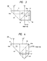
- Figure 3 shows the construction of a second example of polarization illuminating apparatus, and more particularly an apparatus for illuminating a liquid crystal light bulb.
- this polarization illuminating apparatus differs from that shown in Figure 1 in that the P-polarized component Lp transmitted through the acting surface 36a of a polarizing beam splitter 36 intactly emerges from the polarizing beam splitter 36 and the S-polarized component Ls reflected by the acting surface 36a is converted into P-polarized component Lp* by a quarter wavelength optical phase plate 37 and a reflecting plate 38, whereafter it is reflected at a right angle by the total reflection surface 39a of a total reflection prism 39 and emerges from the total reflection prism 39 in parallelism to the P-polarized component Lp.
- the total reflection prism 39 may be formed integrally with a rectangular prism on that side of the polarizing beam splitter 36 which is adjacent to the total reflection prism 39.
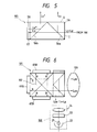
- Figure 4 shows the construction of a third example of polarization illuminating apparatus, and more particularly an apparatus for illuminating a liquid crystal light bulb.
- This polarization illuminating apparatus uses a rectangular prism 40, instead of the reflecting plate 28 of the polarization illuminating apparatus of Figure 1, to reflect the S-polarized component Ls reflected by the acting surface 46a of a polarizing beam splitter 46 without creating unnecessary polarized components.
- the S-polarized component Ls is horizontally inverted and emerges from the rectangular prism 40 to a quarter wavelength optical phase plate 47 and is converted into P-polarized component Lp*.
- the total reflection prism 49 may be formed integrally with the rectangular prism on that side of the polarizing beam splitter 46 which is adjacent to the total reflection prism 49.
- Figure 5 shows the construction of a fourth example of polarization illuminating apparatus, and more particularly an apparatus for illuminating a liquid crystal light bulb.
- This polarization illuminating apparatus is comprised of a polarizing beam splitter 56 having a first acting surface (deposited film formed on one of two inclined surfaces on which three rectangular prisms are adhesively secured together) 56a transmitting the P-polarized component Lp of the incident light beam therethrough and reflecting the S-polarized component Ls of the incident light beam at a right angle and a similar second acting surface (deposited film formed on the other of said two inclined surfaces) 56b having one end thereof in contact with the first acting surface 56a at a right angle, a quarter wavelength optical phase plate 57 having one end thereof in contact with the other end of the second acting surface 56b at an angle of 45° and adhesively secured to that side of the polarizing beam splitter 56 which is opposite to the incidence surface, and a reflecting plate 58 having a reflecting surface adhesively secured to the quarter wavelength plate 57.
- a polarizing beam splitter 56 having a first acting surface (deposited film formed on one of two inclined surfaces on which three rectangular prisms are adhesively secured together) 56a transmitting
- the S-polarized component Ls of the incident light beam from a condenser lens, not shown, is reflected by the first acting surface 56a of the polarizing beam splitter 56 and intactly emerges therefrom.
- the P-polarized component Lp of said incident light beam is transmitted through the first and second acting surfaces 56a and 56b of the polarizing beam splitter 56 and enters the quarter wavelength optical phase plate 57.
- This P-polarized component Lp has its plane of polarization rotated by 90° by the quarter wavelength optical phase plate 57 and the reflecting plate 58 and is converted into S-polarized component Ls*, whereafter it is reflected at a right angle by the second acting surface 56b of the polarizing beam splitter 56, and emerges in the same direction as the S-polarized component Ls.
- the quarter wavelength optical phase plate 57 and the reflecting plate 58 are not disposed on that side of the polarizing beam splitter 56 which is opposite to the emergence side and therefore can be made to operate also as an analyzer (this will be described later in detail).
- Figure 6 shows the construction of a projection type display apparatus having the polarization illuminating apparatus shown in Figure 5.
- This projection type display apparatus has an illuminating system 100 comprising a light source 21, a reflecting mirror 22 comprising a spherical mirror, a heat ray cut filter 23 and a condenser lens 24, the polarizing apparatus 101 shown in Figure 5, a cross dichroic prism 102 having one surface thereof adhesively secured to the emergence surface of the polarizing apparatus 101 and having reflection type liquid crystal light bulbs 65R, 65G and 65B for red, green and blue adhesively secured to the other three surfaces thereof, and a projection lens system 103 provided on that side of the polarizing apparatus 101 which is opposite to the emergence surface for projecting an image made by each light bulb onto a screen, not shown.
- the reflecting mirror 22 comprises a spherical mirror, and the center of the curvature thereof coincides with the center of the light source 21, and the condenser lens 24 has the collimating function and the focus position thereof coincides with the center of the light source 21. Accordingly, the light beam from the light source 21 is converted into a parallel light beam by the lens 24.
- the S-polarized component Ls of a white parallel light beam emitted from the illuminating system 100 is reflected at a right angle by the first acting surface 56a of the polarizing beam splitter 56 which constitutes the polarizing apparatus 101 (see Figure 5), and enters the cross dichroic prism 102.
- the P-polarized component Lp of the white parallel light beam as previously described, is converted into S-polarized component Ls* by the quarter wavelength optical phase plate 57 and the reflecting plate 58, whereafter it is reflected at a right angle by the second acting surface 56b of the polarizing beam splitter 56 (see Figure 5) and enters the cross dichroic prism 102. That is, the white parallel light beam is converted by the polarizing apparatus 101 into a rectilinearly polarized light beam comprising S-polarized components Ls and Ls*, and emerges to the cross dichroic prism 102.
- This rectilinarly polarized light beam is separated into red, green and blue light beams R, G and B by the cross dichroic prism 102, and the light beams R, G and B are projected onto reflection type liquid crystal light bulbs 65R, 65G and 65B for red, green and blue, respectively.
- Liquid crystal used in the reflection type liquid crystal light bubls 65R, 65G and 65B is of the ECB (electrically controlled birefringence) type or the 45° TN type, and has the property of rotating the plane of polarization of the incident light by a voltage applied thereto in conformity with an image signal.
- the incident lights onto the reflection type liquid crystal light bulbs 65R, 65G and 65B are rectilinearly polarized light beams of S-polarized component, but the reflected lights thereof become light beams having P-polarized component in conformity with the signals of the picture elements of the aforementioned image signal. Said reflected lights are combined together by the cross dichroic prism 102, and thereafter are returned to the polarizing apparatus 101.
- the polarizing beam splitter 56 acts as an analyzer, which transmits the P-polarized component Lp ⁇ of the combined reflected light therethrough and projects an image an image light onto the screen, not shown, through the lens system 103.
- part of the S-polarized component Ls ⁇ of the combined reflected light which enters the first acting surface 56a of the polarizing beam splitter 56 is reflected at a right angle by the first acting surface 56a and returns to the illuminating system 100.
- part of the S-polarized component Ls ⁇ which enters the second acting surface 56b of the polarizing beam splitter 56 is reflected at a right angle by the second acting surface 56b and enters the quarter wavelength optical phase plate 57 and therefore, is converted into P-polarized component by the quarter wavelength phase plate 57 and the reflecting plate 58, whereafter it enters the second acting surface 56b and is therefore transmitted through the second acting surface 56b and the first acting surface 56a and returns to the illuminating system 100.
- the polarizing beam splitter 56 of this polarizing apparatus 101 acts as an analyzer.
- this projection type display apparatus converts the white parallel light beam emitted from the illuminating system 100 into a rectilinearly polarized light beam by the polarizing apparatus 101 and can therefore improve the utilization rate of light, and separates and combines the color light beams by the use of the cross dichroic prism 102 and therefore, the back focal length of the lens system 103 can be made remarkably smaller than in the conventional projection type display apparatus of this kind, and the degree of freedom of design of the projection lens 103 can be widened and the entire projection type display apparatus can be made compact. Further, the polarizing apparatus 101 can be made to act also as an analyzer.
- Figures 7A and 7B are a side view and a top plan view, respectively, showing the essential portions of an embodiment of the projection type display apparatus having the polarization illuminating apparatus shown in Figure 1.
- This projection type display apparatus has the already described illuminating system 100, the polarizing apparatus 101 shown in Figure 1, a mirror 77 for reflecting the light beam emitted from the polarizing apparatus 101 downwardly at a right angle, a polarizing beam splitter 78 for reflecting the S-polarized component of the light beam reflected by the mirror 77 at a right angle toward the polarizing apparatus 101 and transmitting the P-polarized component of said light beam therethrough, a cross dichroic prism 102 having one side thereof adhesively secured to the emergence surface of the polarizing beam splitter 78 for said S-polarized component and having reflection type liquid crystal light bulbs 65R, 65G and 65B for red, green and blue, respectively, adhesively secured to the other there sides thereof, and a projection lens 113 provided on that side of the polarizing beam splitter 78 which is opposite to the cross dichoric prism 102.
- the white parallel light beam emitted from the illuminating system 100 enters the polarizing apparatus 101 and as shown in Figure 1, the P-polarized component of this white parallel light beam and the P-polarized component converted by the quarter wavelength optical phase plate 27 and the reflecting plate 28 emerge from the polarizing apparatus 101 to the mirror 77 (the P-polarized component and the converted P-polarized component together will hereinafter be referred to as the P-polarized light beam).
- the P-polarized light beam is totally reflected by the mirror 77 and enters the polarizing beam splitter 78.
- the plane of polarization of the P-polarized light beam becomes a plane of S-polarization relative to the acting surface of the polarizing beam splitter 78 and therefore, this P-polarized light beam is reflected by this acting surface and enters the cross dichroic prism 102.
- the P-polarized light beam which has entered the cross dichroic prism 102 behaves like the rectilinearly polarized light beam which has entered the cross dichroic prism 102 of the projection type display apparatus shown in Figure 6, and enters the polarizing beam splitter 78 as reflected light modulated in the respective reflection type liquid crystal light bulbs 65R, 65G and 65B by an image signal.
- the polarizing beam splitter 78 acts as an analyzer, and the component of said reflected light transmitted through the polarizing beam splitter 78 is projected onto a screen, not shown, through the projection lens system 103 and an image is formed on the screen.
- the improved light utilization rate, the improved degree of freedom of design of the lens system 103 and the compactness of the entire construction can be achieved.
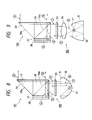
- Figure 8 shows the construction of a further preferred embodiment of the present invention, and more particularly an apparatus for illuminating a liquid crystal light bulb.
- this polarization illuminating apparatus comprises, instead of the reflecting mirror 22 and condenser lens 24 in Figure 1, a rotational parabolic surface mirror 30 having a focus at or near the position of the light source 21 and a rotational parabolic surface mirror 31 forming a rotational parabolic shape also having a focus at or near the position of the light source 21 and located more adjacent to the emergence side than the mirror 30 and whose emergence opening has a shape and a size approximate to those of the opening defined by the light incidence surface I of the polarizing beam splitter 26, and the light beam from the illuminating system 100 is directed to the light incidence surface of the apparatus 101 without so much loss.
- the polarizing beam splitter 26 it is difficult to obtain a transmission factor of 100% for the P-polarized light to the acting surface 26a thereof, and particularly it is more difficult to maintain a high transmission factor for a very wide band like the visible wavelength band. Also, in the case of an incident light ray whose angle of incidence onto the acting surface 26a of the polarizing beam splitter 26 is off an optional angle, the transmission factor of the P-polarized component thereof to the acting surface 26a is reduced more remarkably.
- a plane mirror 33 partly overlapping with the semielliptical mirror 32 and located on the bisecting plane of the two focuses of a rotational elliptical member, and a condenser lens 34 having a focus at the position of the light source 21.
- the light beam 6 ⁇ returning from the polarizing beam splitter 26 to the light source 21 is reflected plural times about the position of the light source 21 by the mirrors 32 and 33 and emerges again as an effective recurrent light beam 7 ⁇ .
- the emergence opening therein is formed into a rectangle or a shape approximate thereto, and of the light beam emitted from the light source 21, in the case of the embodiment shown in Figure 1, at least part of the light beam emerging to the other portion of the rectangular light incidence surface I of the polarizing beam splitter 26 emerges as an effective light beam and also, the light beam returning from the polarizing beam splitter 26 to the light source 21 is effectively utilized as the recurrent light beam.
- the shape of the emergence opening need not always be made coincident with the shape of the incidence opening of the polarizing beam splitter 26, but may be such that the cross-sectional shape and size of the light beam some P-polarized component mixes with the light beam 3 ⁇ of the incident light 1 ⁇ in Figure 8 which is reflected by the acting surface 26a.
- a light beam 4 ⁇ which reciprocally travels through the quarter wavelength optical phase plate 27, the amount of retardation thereof differs depending on wavelength and therefore, there is created a component whose direction of polarization does not completely rotate by 90°.
- said lost light can be again utilized as effective light to thereby further enhance the light utilization rate.
- the light beam 6 ⁇ which returns toward the light source in Figure 8 is reflected by the reflecting mirror 30 and is condensed toward the light source 21 lying at the focus position of the mirror 30.
- a light ray 7 ⁇ transmitted through the light source 21 is again condensed at the focus position through the reflecting mirror 31 and the reflecting mirror 30, and further emerges again as a substantially parallel light beam to the polarizing beam splitter 26 through the reflecting mirror 30.
- the recurrent light beam As recurrent light beam, like that shown in the first embodiment, emerges as polarized light from the light emergence surface O through the polarizing beam splitter 26, etc.
- a parabolic mirror confocal to the reflecting mirror 30 is used as the reflecting mirror 31, but if instead, a mirror unit which causes the light beam returning from the polarizing beam splitter 26 to the light source to emerge again as an effective light beam through the position of the light source, such as an appropriate spherical mirror having its center at the focus position of the reflecting mirror, is added, there will be obtained a similar effect. Also, even a form in which the reflecting mirror 31 is eliminated could obtain a certain degree of effect.
- Figure 9 shows another embodiment in which an effective recurrent light beam is obtained, and more particularly an apparatus for illuminating a liquid crystal light bulb.
- the differences of this embodiment from the embodiment shown in Figure 8 lie in a semielliptical mirror 32 having a forcus at or system 100 can be combined together to assemble a polarization illuminating apparatus.
- the cross-sectional shape and size of the light beam from the illuminating system 100 can be made coincident with or similar to the shape (rectangular shape) and size of the light incidence surface of each of various polarizing apparatuses, thereby causing the light beam to efficiently enter each of the various polarizing apparatuses from the illuminating system 100.
- the polarizing apparatus is a polarizing beam splitter or a polarizing plate.
- projection type projections are shown by way of example in Figures 6 to 7B, the polarization illuminating apparatus of each of the above-described embodiments can also be applied to the transmission type projectors as shown in the above-mentioned publications, a flat display panel using a light bulb, a printer using a light bulb, or other optical apparatus utilizing a polarized beam than such a display instrument and such a recording instrument.
- the illuminating system shown in Figure 8 or 9 is used as the illuminating system 100, the light emergence opening of the system tens to become small and the angle of opening of the light beam directed from the system to the polarizing apparatus tends to become great, but if the apparatus shown in travelling toward said incidence opening can be made substantially the same as or similar to those of the light incidence surface I.
- the means for obtaining the recurrent light beam as shown in Figures 8 and 9 attains a further effect particularly in the projection type display apparatus using the reflection type light bulbs as shown in Figures 7A and 7B. That is, of the light beams emerging from the reflection type light bulbs 65R, 65G and 65B in Figures 7A and 7B to the polarizing beam splitter 78, the reflected light beam consisting chiefly of S-polarized component enters the polarizing apparatus 101 as P-polarized component, and is converted into S-polarized and P-polarized components and returns to the illuminating system 100. In the present construction, it becomes possible to utilize this light beam again as an effective recurrent light beam.
- the polarizing apparatus 100 is provided with a polarizing beam splitter and a plane-of-polarization rotator comprising an arrangement of a quarter wavelength plate and a mirror, but the form of the polarizing apparatus is not restricted thereto.
- the shape of the cut-away portions 321-324 is the shape of the line of intersection between the rotational parabolic surface mirror 30 and a square post having a cross-section of the same size as the rectangular opening 325 when the square post is fitted to the rotational parabolic surface mirror 30, i.e., a bow-like shape.
- the spherical mirror 301 has in the central portion thereof a rectangular opening 331 of the same size as the rectangular opening 325 in the rotational parabolic surface mirror 30, and has a circular opening 332 on the opposite side to the rectangular opening 331, and is disposed so that the circular opening 332 and the rectangular opening 325 in the rotational parabolic surface mirror 30 may be opposed to each other and the center of curvature thereof may coincide with the focus of the rotational parabolic surface mirror 30.
- This system is provided with a rotational parabolic surface mirror 30, a light source 21 provided near the forcus of the rotational parabolic surface mirror 30, and a spherical mirror 301 having a rectangular opening 331 (see Figure 12) in the central portion thereof and disposed in opposed relationship with the rotational parabolic surface mirror 30 so that the center of curvature (the center of sphere) thereof may be lie near the light source 21.
- the rotational parabolic surface mirror 30, as shown in Figure 11, has bow-shaped cut-away portions 321-324 formed in the upper surface, the lower surface utilized as original illuminating light and therefore, the light utilization rate can be improved. Also, this light beam emerges as illuminating light by two reflections as previously described, and this leads to the advantage that reflection loss is small.
- the light source 21 use is made of one having such a light distribution that almost all light enters the rotational parabolic surface mirror 30 and the spherical mirror 301, there will be obtained a rectangular illuminating light beam of very high light utilization rate.
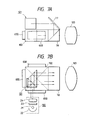
- Figure 13 is a schematic view showing a second modification of the illuminating system of the present invention.
- This system is provided with a rotational elliptical mirror 46, a light source 21 provided near the first focus of the rotational elliptical mirror 46, and a spherical mirror 30 having a rectangular opening in the central portion thereof and disposed in opposed relationship with the rotational elliptical mirror 46 so that the center of curvature thereof may lie near the light source 21.
- the rotational elliptical mirror 46 has bow-shaped cut-away portions formed on the upper surface, the lower surface and the opposite sides thereof so that the opening therein may be a rectangular opening when it is seen from on the optic axis A passing through the central portion of the emergence surface.
- the shape of these cut-away portions is the shape of the line of intersection between the rotational elliptical mirror 46 and a square post having a cross-section of the same size as a rectangular opening to be formed therein when the square post is fitted into a circular opening in the rotational elliptical mirror 46.
- the spherical mirror 301 like the spherical mirror 301 shown in Figure 12, has in the central portion thereof a rectangular opening of the same size as the rectangular opening in the rotational elliptical mirror 46 and has a circular opening on the side opposite to said rectangular opening, and is disposed so that said circular opening and the rectangular opening in the rotational elliptical mirror 46 may be opposed to each other and the center of curvature thereof may coincide with the focus of the rotational elliptical mirror 46.
- the light from the light source 21 can be made to efficiently emerge forwardly by the action of the spherical mirror 301. Since the rotational elliptical mirror 46 is used instead of the rotational parabolic surface mirror 30 shown in Figure 10, the light beam reflected by the rotational elliptical mirror 46 becomes convergent light condensed toward the second focus position of the by four light rays ⁇ 1 , ⁇ 2 , ⁇ 1 and ⁇ 2 whereafter it emerges as parallel light through the rectangular opening 325 in the rotational parabolic surface mirror 30 and the rectangular opening 331 in the spherical mirror 301.
- the light beam travelling toward the four cut-away portions 321-324 of the rotational parabolic surface mirror 30 and more or less outwardly of the cut-away portions 321-324 is reflected toward the light source 21 by the spherical mirror 301 as indicated, for example, by four light rays ⁇ 1 , ⁇ 2 , ⁇ 1 and ⁇ 2 , and part of this reflected light beam is intercepted or scattered by the light source 21, but the rest of the reflected light beam passes through the light source 21 and is reflected by the rotational parabolic surface mirror 30, whereafter it emerges as parallel light through the rectangular opening 325 in the rotational parabolic surface mirror 30 and the rectangular opening 331 in the spherical mirror 301.
- the light beam travelling toward the four cut-away portions 321-324 of the rotational parabolic surface mirror 30 and more or less outwardly of the cut-away portions 321-324 can also be rotational elliptical mirror 46.
- the optical system is assembled so that this convergent light may be within the pupil (aperture stop) of the lens system 103 when the illuminating system of the present embodiment is used in lieu of the image display illuminating system 100 of the image display apparatus previously shown, the light utilization rate can be improved.
- the brightness of the image can be made greater than in the prior art.
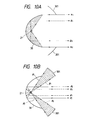
- Figures 14A and 14B show another embodiment of the illuminating system of the present invention.
- This illuminating system is provided with a first parabolic surface mirror 30 having a circular opening therein, a light source 21 disposed near the focus of the first parabolic surface mirror 30, and a second parabolic surface mirror 303 as a curved surface mirror having a rectangular opening 304 in the central portion thereof and having a circular opening of substantially the same diameter as the diameter of the opening in the first parabolic surface mirror 30 and a curvature smaller than the curvature of the first parabolic surface mirror 30, the focus of the second parabolic surface mirror 303 being made coincident with the focus of the first parabolic surface mirror 30, and the second parabolic surface mirror 303 and the first parabolic surface mirror 30 and joined together with the circular opening in the mirror 303 opposed to the circular opening in the mirror 30.
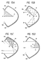
- the light emitted from the light source 21 the light emitted within the range indicated by hatching surrounded by the light rays ⁇ 1 and ⁇ 2 of Figure 15A is emitted toward the rectangular opening 304 in the second parabolic surface mirror 303 and intactly emerges as direct light.
- the light indicated by a light ray ⁇ 1 in Figure 15B which is emitted from the light source 21 toward the upper end portion of the rectangular opening 304 in the second parabolic surface mirror 303 is reflected as parallel light toward the first parabolic surface mirror 30 by the second parabolic surface mirror 303 because the focus of the second parabolic surface mirror 303 is made coincident with the focus of the first parabolic surface mirror 30 and the light source 21 is disposed near said focuses, whereafter it is reflected toward the light source 21 by the first parabolic surface mirror 30.
- this reflected light is intercepted or scattered by the light source 21, while the rest of it passes through the light source 21 and is again reflected as parallel light toward the second parabolic surface mirror 303 by the first parabolic surface mirror 30, and thereafter is reflected toward the light source 21 by the second parabolic surface mirror 303.
- This reflected light except some of it, passes through the light source 21 again and is reflected by the first parabolic surface mirror 30, and thereafter emerges as parallel light from the rectangular opening 304 in the second parabolic surface mirror 303.
- the light indicated by the light ray ⁇ 1 is reflected two times by the second parabolic surface mirror 303 and three times by the first parabolic surface mirror 2, thus five times in total, whereafter it emerges from the rectangular opening 304 in the second parabolic surface mirror 303.
- the light emitted from the light source 21 the light emitted within the range indicated by hatching surrounded by the light rays ⁇ 1 and ⁇ 2 of Figure 15B is reflected five times in the same manner, whereafter it emerges as parallel light from the rectangular opening 304 in the second parabolic surface mirror 303.
- Light indicated by a light ray ⁇ 1 in Figure 15C is reflected as parallel light toward the first parabolic surface mirror 30 by the second parabolic surface mirror 303 for the same reason as that set forth in item (2) above, and thereafter is reflected toward the light source 21 by the first parabolic surface mirror 30.
- This reflected light except some of it, passes through the light source 21 and is again reflected as parallel light by the first parabolic surface mirror 30, and thereafter emerges from the rectangular opening 304 in the second parabolic surface mirror 303.
- the light indicated by the light ray ⁇ 1 is reflected once by the second parabolic surface mirror 303 and twice by the first parabolic surface mirror 30, thus three times in total; and thereafter emerges from the rectangular opening 304 in the second parabolic surface mirror 30.
- light indicated by a light ray ⁇ 2 in Figure 15C is reflected as parallel light toward the second parabolic surface mirror 303 by the first parabolic surface mirror 30, and thereafter is reflected toward the light source 21 by the second papabolic surface mirror 303.
- This reflected light except some of it, passes through the light source 21 and is again reflected as parallel light by the first parabolic surface mirror 30, and thereafter emerges from the rectangular opening 304 in the second parabolic surface mirror 303.
- the light indicated by the light ray ⁇ 2 is also reflected once by the second parabolic surface mirror 303 and twice by the first parabolic surface mirror 30, thus three times in total, and thereafter emerges from the rectangular opening 304 in the second parabolic surface mirror 303.
- the light emitted from the light source 21 the light emitted within the range indicated by hatching surrounded by the light ray ⁇ 1 and ⁇ 2 of Figure 15C is reflected three times in the same manner, and thereafter emerges from the rectangular opening 304 in the second parabolic surface mirror 303.
- the light emitted from the light source 1 the light emitted within the range indicated by hatching surrounded by the light rays ⁇ 1 and ⁇ 2 of Figure 15D is reflected once in the same manner, and thereafter emerges from the rectangular opening 304 in the second parabolic surface mirror 303.
- the light emitted from the light source through the vicinity of the end of the opening in the parabolic surface mirror which was heretofore not utilized at all can also be made to emerge as parallel light from the rectangular opening 304 in the second parabolic surface mirror 303 and be applied to the rectangular display area of the liquid crystal light bulb, not shown, and the light incidence surface I of the polarizing apparatus 101 and therefore, the light utilization rate can be improved.
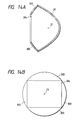
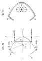
- the coordinates of the upper and lower junctions A and A 1 of the first and second parabolic surface mirrors 30 and 303 are: A (- P 2 2 , (P 1 P 2 ) 1/2 ) A 1 (- P 2 2 , - (P 1 P 2 ) 1/2 )
- the ratio of the length (diameter) of the circular opening in the first parabolic surface mirror 30 to the longitudinal length of the rectangular opening 304 in the second parabolic surface mirror 303 is 5:3 (see Figure 16) and therefore, the coordinates of two points B and B 1 on the first parabolic surface mirror 30 at which the upper and lower ends of the rectangular opening 304 are equal to the y-axis are: B(-0.18 P 2 , 0.6 ⁇ (P 1 P 2 ) 1/2 ) B 1 (-0.18 P 2 , -0.6 ⁇ (P 1 P 2 ) 1/2 )
- the curvature (1/P 2 ) of the second parabolic surface mirror 303 can be set to 0.6 time the curvature (1/P 1 ) of the first parabolic surface mirror 30.
- the curvature (1/P 1 ) of the first parabolic surface mirror 30 and the curvature (1/P 2 , 1/P 3 ) of the second parabolic surface mirror 303 are made equal to each other, the light emitted from the light source 21 installed at the focus position toward the first parabolic surface mirror 30 or the second parabolic surface mirror 303 always passes along the same optical path and is reflected between these two parabolic surface mirrors and therefore does not emerge from the rectangular opening 304 in the second parabolic surface mirror 303.
- the curvature (1/P 5 ) of the second parabolic surface mirror 303 in the lateral direction of the object to be illuminated such as the liquid crystal light bulb at this time can be set to 0.64 time the curvature (1/P 1 ) of the first parabolic surface mirror 303.
- the second parabolic surface mirror 303 having the rectangular opening 304 formed in the central portion thereof and having a circular opening of the same size as that in the first parabolic surface mirror 30 and a curvature smaller than the curvature of the first parabolic surface mirror 30 is joined to the first parabolic surface mirror with the focus thereof made coincident with the focus of the first parabolic surface mirror 30 and with the circular opening therein opposed to the circular opening in the first parabolic surface mirror 30.
- a spherical mirror having a rectangular opening in the central portion thereof and having a circular opening of the same size as that in the first parabolic surface mirror 30 and a curvature smaller than the curvature (1/P 1 ) of the first parabolic surface mirror 30 can also cause the light which could heretofore not be utilized to be reflected several times between the spherical mirror and the first parabolic surface mirror 30 and thereafter emerge from said rectangular opening and can attain a similar effect by joining the spherical mirror to the first parabolic surface mirror 30 with the circular opening in the spherical mirror opposed to the circular opening in the first parabolic surface mirror 30.
- the deterioration of aberrations when the spherical mirror is used is of the same degree as that when the parabolic surface mirror is used and therefore, when the ease of manufacture is taken into consideration, the use of the spherical mirror leads to the low cost of the illuminating system.
- this light source can be installed so that the direction of light emission in which the light emission angle distribution is 0 may be perpendicular to the irradiating surface of the liquid crystal light bulb or the polarizing apparatus, thereby reducing the proportion of the direct light emitted directly from the light source toward the object to be illuminated such as the liquid crystal light bulb, and almost all light is reflected by the first and second parabolic surface mirrors and emerges as parallel light to the object to be illuminated such as the liquid crystal light bulb and thus, the condenser lens will become unnecessary.
- the second parabolic surface mirror and the spherical mirror need not always be joined to the first parabolic surface mirror.
- the size of the openings in the second parabolic surface mirror and the spherical mirror which are adjacent to the first parabolic surface mirror may be more or less larger than the size of the opening in the first parabolic surface mirror.
- the center of curvature of the spherical mirror and the focus of the first parabolic surface mirror may be made substantially coincident with each other.
- the brightness of image can be made higher than in the prior art.
Abstract
Description
Claims (11)
- A polarisation converting apparatus comprising:which apparatus is characterised in that:polarising means (101) having a light incidence surface (I) defining a light entry aperture of rectangular shape; andillumination means (100), for illuminating said polarising means (101), being arranged in front of the light entry aperture of said polarizing means (101), and including a reflector (30,31; 33,32; 30,301; 46,301; 30,303) having a central axis and a light source (21) for emitting non-polarised light, arranged substantially on said axis at a focus of said reflector whereby light from said light source is once or repeatedly reflected from the surface of said reflector (30,31; 33,32; 30,301; 46,301; 30,303) such that it is directed as a parallel light beam or a condensed light beam towards said light entry aperture (I);said reflector (30,31; 33,32; 30,301; 46,301; 30,303) has a front opening substantially centred on said axis arranged in front of said light source (21), and defining a light exit aperture of rectangular shape; andsaid light beam which emerges from said exit aperture is directed as a beam having a cross-section at said light incidence surface (I) of said polarising means (101) of substantially the same size and rectangular shape as that of said light entry aperture (I).
- A polarising converting apparatus according to claim 1 wherein:said reflector (30,31) consists of rotational parabolic surface concave front and rear mirrors (31,30), which mirrors are arranged to face one another, are substantially coaxial and substantially confocal, said front mirror (31) having smaller parabolic curvature than said rear mirror (30), said rear mirror (30) having an opening larger than said frontal opening; andsaid light source (21) is arranged substantially at the common focus of said front and rear mirrors (31,30).
- A polarising converting apparatus according to claim 1 wherein:said reflector (33,32) consists of a rotational elliptical surface front mirror (32) and a plane rear mirror (33) arranged substantially orthogonal to said axis, substantially midway between the front and rear foci of said front mirror (32);said light source (21) is arranged substantially at the front focus of said front mirror (32); andsaid illumination means also includes a condenser lens (34), arranged in front of said light exit aperture with its rear focus substantially coincident with the front focus of said front mirror (32).
- A polarising converting apparatus according to claim 1 wherein:said reflector (30,301) consists of a spherical concave front mirror (301) and a rotational parabolic surface rear mirror (30), which mirrors are arranged facing one another, are substantially co-axial and the centre of curvature of said front mirror (301) is arranged substantially coincident with the focus of said rear mirror (30); andsaid light source (21) is arranged substantially at the focus of said rear mirror (30).
- A polarising converting apparatus according to claim 4 wherein:
said front mirror (301) has said front opening (331) defining said exit aperture and said rear mirror (30) has a front opening (325) which when viewed from said axis is of the same size and rectangular shape as said exit aperture (331). - A polarising converting apparatus according to claim 1 wherein:said reflector (46,301) consists of a spherical concave front mirror (301) and a rotational elliptical surface rear mirror (46), which mirrors are arranged facing one another, are substantially co-axial and the centre of curvature of said front mirror (301) is arranged substantially co-incident with the rear focus of said rear mirror (46); andsaid light source (21) is arranged substantially at the rear focus of said rear mirror (46).
- A polarising converting apparatus according to any preceding claim wherein said reflector (30,31; 33,32; 30,301; 46,301; 30,303) is arranged with said central axis orthogonal to said light incidence surface (I).
- A polarising converting apparatus according to either of claims 2 or 5, wherein said light source (21) emits light with minimum intensity in the direction of said light incidence surface (I), whereby substantially all light reaching said light incidence surface is reflected light.
- A polarization converting apparatus according to any preceding claim, wherein said polarising means (101) comprises a polarising plate or a polarising beam splitter (26).
- A polarisation converting apparatus according to claim 9, wherein said polarising means (101) has means (26) for dividing said non-polarised light into first and second polarised lights whose planes of polarisation are orthogonal to each other, and means (27,28) for making the planes of polarisation of said first and second polarised lights coincident with each other.
- Apparatus according to any preceding claim, wherein said light source (21) is omitted.
Applications Claiming Priority (6)
| Application Number | Priority Date | Filing Date | Title |
|---|---|---|---|
| JP116728/90 | 1990-05-08 | ||
| JP2116728A JPH0414032A (en) | 1990-05-08 | 1990-05-08 | Illuminating device and image display device provided therewith |
| JP174442/90 | 1990-07-03 | ||
| JP2174442A JPH0463321A (en) | 1990-07-03 | 1990-07-03 | Lighting system and image display device provided with the lighting system |
| JP313597/90 | 1990-11-19 | ||
| JP31359790A JP2888624B2 (en) | 1990-11-19 | 1990-11-19 | Polarized illumination device and projection display device having the polarized illumination device |
Publications (3)
| Publication Number | Publication Date |
|---|---|
| EP0456427A2 EP0456427A2 (en) | 1991-11-13 |
| EP0456427A3 EP0456427A3 (en) | 1992-10-14 |
| EP0456427B1 true EP0456427B1 (en) | 1998-01-28 |
Family
ID=27313215
Family Applications (1)
| Application Number | Title | Priority Date | Filing Date |
|---|---|---|---|
| EP91304028A Expired - Lifetime EP0456427B1 (en) | 1990-05-08 | 1991-05-03 | Polarization converting apparatus |
Country Status (5)
| Country | Link |
|---|---|
| US (1) | US5461500A (en) |
| EP (1) | EP0456427B1 (en) |
| AT (1) | ATE162921T1 (en) |
| CA (1) | CA2041926C (en) |
| DE (1) | DE69128810T2 (en) |
Cited By (2)
| Publication number | Priority date | Publication date | Assignee | Title |
|---|---|---|---|---|
| CN101236305B (en) * | 2007-02-02 | 2011-06-01 | 上海飞锐光电科技有限公司 | Polarization converting device |
| US11619826B2 (en) * | 2018-04-17 | 2023-04-04 | Samsung Electronics Co., Ltd. | Augmented reality (AR) display apparatus and method |
Families Citing this family (18)
| Publication number | Priority date | Publication date | Assignee | Title |
|---|---|---|---|---|
| JPH05150191A (en) * | 1991-12-02 | 1993-06-18 | Nippon Avionics Co Ltd | Linear polarized light conversion device |
| JPH05264904A (en) * | 1992-03-18 | 1993-10-15 | Canon Inc | Illuminating optical system and projection type image display device using the system |
| US5903388A (en) * | 1992-06-11 | 1999-05-11 | Sedlmayr Steven R | High efficiency electromagnetic beam projector and systems and method for implementation thereof |
| JPH0694902A (en) * | 1992-09-11 | 1994-04-08 | Canon Inc | Optical element, light source, liquid crystal optical element, polarizing illuminator, illuminating optical device, polarized light separating element, polarizer, picture projector and stereoscopic image display method |
| JPH07294850A (en) * | 1994-04-22 | 1995-11-10 | Canon Inc | Illuminator and projector using the same |
| KR100400114B1 (en) * | 1994-06-01 | 2003-12-31 | 코닌클리케 필립스 일렉트로닉스 엔.브이. | Video projection device with high efficiency lighting devices and such devices |
| KR0164463B1 (en) * | 1994-11-25 | 1999-03-20 | 이헌조 | Optical apparatus of liquid crystal projector |
| JP2738324B2 (en) * | 1995-01-23 | 1998-04-08 | 日本電気株式会社 | Projection type liquid crystal display |
| KR0174852B1 (en) * | 1995-04-18 | 1999-03-20 | 김주용 | Advanced optical system using optical deflection prism for panel type lcd |
| US5995284A (en) * | 1996-03-29 | 1999-11-30 | 3M Innovative Properties Company | Polarized illumination system for LCD projector |
| US6104536A (en) * | 1998-09-18 | 2000-08-15 | 3M Innovative Properties Company | High efficiency polarization converter including input and output lenslet arrays |
| IT1313117B1 (en) * | 1999-08-25 | 2002-06-17 | Morton Int Inc | VACUUM APPLICATION EQUIPMENT EQUIPPED WITH CONVEYING VEHICLES PROCEDURE FOR APPLYING A DRY FILM RESIST TO A PANEL OF |
| KR100534575B1 (en) * | 2001-04-24 | 2005-12-07 | 삼성에스디아이 주식회사 | Light Converting Apparatus of Projection System |
| JP2004185781A (en) * | 2002-12-06 | 2004-07-02 | Pioneer Electronic Corp | Optical device and optical pickup |
| KR100520604B1 (en) * | 2003-01-15 | 2005-10-10 | 삼성전자주식회사 | Wavelength division multiplexed light source and system for passive optical network wsing the same |
| US20070211471A1 (en) * | 2003-10-27 | 2007-09-13 | Wimberly Randal L | Dual Reflector System |
| KR100694117B1 (en) * | 2005-03-30 | 2007-03-12 | 삼성전자주식회사 | Illuminating unit and image projection apparatus employing the same |
| DE102005032934A1 (en) * | 2005-07-12 | 2007-01-25 | Philipps-Universität Marburg | Invention concerning reflector systems |
Family Cites Families (29)
| Publication number | Priority date | Publication date | Assignee | Title |
|---|---|---|---|---|
| DE554927C (en) * | 1932-07-15 | Wilhelm Volkmann Dr | Illumination mirror arrangement | |
| US1223752A (en) * | 1915-01-14 | 1917-04-24 | Western Electric Co | Apparatus for reflecting light-rays. |
| US1503766A (en) * | 1923-12-05 | 1924-08-05 | Pictet Lucien | Device for projecting and viewing stereoscopic pictures |
| US1717360A (en) * | 1926-05-01 | 1929-06-18 | Apparatus jfor polarizing ultra-violet radiations | |
| FR711306A (en) * | 1930-02-18 | 1931-09-07 | Lighting device | |
| US2272186A (en) * | 1939-07-19 | 1942-02-10 | Edward P Creehan | Radiant energy projector |
| GB690467A (en) * | 1950-12-11 | 1953-04-22 | Brush Dev Co | Device for controlling light intensity |
| FR1058232A (en) * | 1952-03-13 | 1954-03-15 | Reflection device | |
| US2887566A (en) * | 1952-11-14 | 1959-05-19 | Marks Polarized Corp | Glare-eliminating optical system |
| US3508809A (en) * | 1967-12-29 | 1970-04-28 | Rca Corp | High efficiency light polarization system |
| US3588493A (en) * | 1968-04-29 | 1971-06-28 | Grimes Manufacturing Co | Projecting lamps having reflector which form rectangular patterns of light |
| US3566099A (en) * | 1968-09-16 | 1971-02-23 | Polaroid Corp | Light projection assembly |
| CA1127867A (en) * | 1978-03-20 | 1982-07-20 | Albert Brunsting | Ellipsoid radiation collector and method |
| FR2440667A1 (en) * | 1978-10-31 | 1980-05-30 | Thomson Csf | OPTICAL IMAGE REPRODUCING DEVICE USING A LIQUID CRYSTAL CELL AND FACSIMILE COMPRISING SUCH A DEVICE |
| US4525413A (en) * | 1981-03-02 | 1985-06-25 | Polaroid Corporation | Optical device including birefringent polymer |
| JPS5866909A (en) * | 1981-10-16 | 1983-04-21 | Fujitsu Ten Ltd | Illuminating device |
| JPS59127019A (en) * | 1983-01-11 | 1984-07-21 | Canon Inc | Printer head |
| GB8600022D0 (en) * | 1986-01-02 | 1986-02-12 | Rca Corp | Arrangement to minimize reflected ambient light |
| US4864390A (en) * | 1986-08-22 | 1989-09-05 | North American Philips Corporation | Display system with equal path lengths |
| US4989076A (en) * | 1987-01-27 | 1991-01-29 | Canon Kabushiki Kaisha | Video projection apparatus |
| US5146248A (en) * | 1987-12-23 | 1992-09-08 | North American Philips Corporation | Light valve projection system with improved illumination |
| US4912614A (en) * | 1987-12-23 | 1990-03-27 | North American Philips Corporation | Light valve projection system with non imaging optics for illumination |
| US5042921A (en) * | 1988-10-25 | 1991-08-27 | Casio Computer Co., Ltd. | Liquid crystal display apparatus |
| US4936659A (en) * | 1989-01-26 | 1990-06-26 | Rockwell International Corporation | Liquid crystal display brightness enhancer |
| US4973139A (en) * | 1989-04-07 | 1990-11-27 | Hughes Aircraft Company | Automotive head-up display |
| JPH03175412A (en) * | 1989-12-05 | 1991-07-30 | Victor Co Of Japan Ltd | Polarization converting element |
| US5142387A (en) * | 1990-04-11 | 1992-08-25 | Mitsubishi Denki Kabushiki Kaisha | Projection-type display device having light source means including a first and second concave mirrors |
| JP2961807B2 (en) * | 1990-04-20 | 1999-10-12 | 三菱電機株式会社 | Projection display device |
| JPH04218015A (en) * | 1990-07-27 | 1992-08-07 | Victor Co Of Japan Ltd | Polarization conversion element and dislay device |
-
1991
- 1991-05-03 DE DE69128810T patent/DE69128810T2/en not_active Expired - Fee Related
- 1991-05-03 EP EP91304028A patent/EP0456427B1/en not_active Expired - Lifetime
- 1991-05-03 AT AT91304028T patent/ATE162921T1/en not_active IP Right Cessation
- 1991-05-06 CA CA002041926A patent/CA2041926C/en not_active Expired - Fee Related
-
1994
- 1994-08-22 US US08/293,738 patent/US5461500A/en not_active Expired - Fee Related
Cited By (2)
| Publication number | Priority date | Publication date | Assignee | Title |
|---|---|---|---|---|
| CN101236305B (en) * | 2007-02-02 | 2011-06-01 | 上海飞锐光电科技有限公司 | Polarization converting device |
| US11619826B2 (en) * | 2018-04-17 | 2023-04-04 | Samsung Electronics Co., Ltd. | Augmented reality (AR) display apparatus and method |
Also Published As
| Publication number | Publication date |
|---|---|
| ATE162921T1 (en) | 1998-02-15 |
| CA2041926A1 (en) | 1991-11-09 |
| US5461500A (en) | 1995-10-24 |
| DE69128810T2 (en) | 1998-05-28 |
| EP0456427A3 (en) | 1992-10-14 |
| CA2041926C (en) | 1995-12-12 |
| DE69128810D1 (en) | 1998-03-05 |
| EP0456427A2 (en) | 1991-11-13 |
Similar Documents
| Publication | Publication Date | Title |
|---|---|---|
| EP0456427B1 (en) | Polarization converting apparatus | |
| EP0561388B1 (en) | Illuminating optical system and projector utilizing the same | |
| CA2036918C (en) | Projector | |
| EP0457605B1 (en) | Polarization converting device and polarized-light illuminating system using the device and image display unit using the device | |
| US6348997B1 (en) | Polarizing illuminating device and projector | |
| KR100427897B1 (en) | Polarized light illumination apparatus, display apparatus using the same, and projection display apparatus | |
| JP2828297B2 (en) | Reflective projector | |
| JPH11234598A (en) | Polarized lighting device and projection type display device | |
| US5590942A (en) | Polarizing conversion unit, illuminating device and projector using them | |
| EP0746164B1 (en) | Lighting device transformed in the direction of polarization and projection type image display device using the same | |
| JP3596322B2 (en) | Reflective LCD projector | |
| US6132047A (en) | Polarized light illumination device and projector | |
| JP3578020B2 (en) | Reflective LCD projector | |
| JP3986136B2 (en) | Polarized light source device | |
| JP2004185033A (en) | Polarized light converting element, polarized light lighting device, and display device and projection type display device using same | |
| US6115183A (en) | Lighting device | |
| CA2032680C (en) | Image display apparatus | |
| JPH1164850A (en) | Polarization illuminating device and projection type liquid crystal display device | |
| EP1130450A1 (en) | Polarized light illuminator and projection display | |
| JPH0566367A (en) | Polarized light illumination device and projection display device equipped with the same | |
| JP3455154B2 (en) | Illumination device and projector having the same | |
| JP2888624B2 (en) | Polarized illumination device and projection display device having the polarized illumination device | |
| JPH06202041A (en) | Polarized light illuminating device and projection type display device | |
| JPH09304734A (en) | Polarization illuminating device and projection type display device | |
| JPH06265895A (en) | Light source device |
Legal Events
| Date | Code | Title | Description |
|---|---|---|---|
| PUAI | Public reference made under article 153(3) epc to a published international application that has entered the european phase |
Free format text: ORIGINAL CODE: 0009012 |
|
| AK | Designated contracting states |
Kind code of ref document: A2 Designated state(s): AT BE CH DE DK ES FR GB GR IT LI LU NL SE |
|
| PUAL | Search report despatched |
Free format text: ORIGINAL CODE: 0009013 |
|
| AK | Designated contracting states |
Kind code of ref document: A3 Designated state(s): AT BE CH DE DK ES FR GB GR IT LI LU NL SE |
|
| 17P | Request for examination filed |
Effective date: 19930301 |
|
| 17Q | First examination report despatched |
Effective date: 19950131 |
|
| GRAG | Despatch of communication of intention to grant |
Free format text: ORIGINAL CODE: EPIDOS AGRA |
|
| GRAG | Despatch of communication of intention to grant |
Free format text: ORIGINAL CODE: EPIDOS AGRA |
|
| GRAG | Despatch of communication of intention to grant |
Free format text: ORIGINAL CODE: EPIDOS AGRA |
|
| GRAH | Despatch of communication of intention to grant a patent |
Free format text: ORIGINAL CODE: EPIDOS IGRA |
|
| GRAH | Despatch of communication of intention to grant a patent |
Free format text: ORIGINAL CODE: EPIDOS IGRA |
|
| GRAA | (expected) grant |
Free format text: ORIGINAL CODE: 0009210 |
|
| AK | Designated contracting states |
Kind code of ref document: B1 Designated state(s): AT BE CH DE DK ES FR GB GR IT LI LU NL SE |
|
| PG25 | Lapsed in a contracting state [announced via postgrant information from national office to epo] |
Ref country code: IT Free format text: LAPSE BECAUSE OF FAILURE TO SUBMIT A TRANSLATION OF THE DESCRIPTION OR TO PAY THE FEE WITHIN THE PRESCRIBED TIME-LIMIT;WARNING: LAPSES OF ITALIAN PATENTS WITH EFFECTIVE DATE BEFORE 2007 MAY HAVE OCCURRED AT ANY TIME BEFORE 2007. THE CORRECT EFFECTIVE DATE MAY BE DIFFERENT FROM THE ONE RECORDED. Effective date: 19980128 Ref country code: LI Free format text: LAPSE BECAUSE OF FAILURE TO SUBMIT A TRANSLATION OF THE DESCRIPTION OR TO PAY THE FEE WITHIN THE PRESCRIBED TIME-LIMIT Effective date: 19980128 Ref country code: ES Free format text: THE PATENT HAS BEEN ANNULLED BY A DECISION OF A NATIONAL AUTHORITY Effective date: 19980128 Ref country code: NL Free format text: LAPSE BECAUSE OF FAILURE TO SUBMIT A TRANSLATION OF THE DESCRIPTION OR TO PAY THE FEE WITHIN THE PRESCRIBED TIME-LIMIT Effective date: 19980128 Ref country code: CH Free format text: LAPSE BECAUSE OF FAILURE TO SUBMIT A TRANSLATION OF THE DESCRIPTION OR TO PAY THE FEE WITHIN THE PRESCRIBED TIME-LIMIT Effective date: 19980128 Ref country code: BE Free format text: LAPSE BECAUSE OF FAILURE TO SUBMIT A TRANSLATION OF THE DESCRIPTION OR TO PAY THE FEE WITHIN THE PRESCRIBED TIME-LIMIT Effective date: 19980128 Ref country code: AT Free format text: LAPSE BECAUSE OF FAILURE TO SUBMIT A TRANSLATION OF THE DESCRIPTION OR TO PAY THE FEE WITHIN THE PRESCRIBED TIME-LIMIT Effective date: 19980128 Ref country code: GR Free format text: LAPSE BECAUSE OF FAILURE TO SUBMIT A TRANSLATION OF THE DESCRIPTION OR TO PAY THE FEE WITHIN THE PRESCRIBED TIME-LIMIT Effective date: 19980128 |
|
| REF | Corresponds to: |
Ref document number: 162921 Country of ref document: AT Date of ref document: 19980215 Kind code of ref document: T |
|
| REG | Reference to a national code |
Ref country code: CH Ref legal event code: EP |
|
| REF | Corresponds to: |
Ref document number: 69128810 Country of ref document: DE Date of ref document: 19980305 |
|
| ET | Fr: translation filed | ||
| PG25 | Lapsed in a contracting state [announced via postgrant information from national office to epo] |
Ref country code: SE Free format text: LAPSE BECAUSE OF FAILURE TO SUBMIT A TRANSLATION OF THE DESCRIPTION OR TO PAY THE FEE WITHIN THE PRESCRIBED TIME-LIMIT Effective date: 19980428 Ref country code: DK Free format text: LAPSE BECAUSE OF FAILURE TO SUBMIT A TRANSLATION OF THE DESCRIPTION OR TO PAY THE FEE WITHIN THE PRESCRIBED TIME-LIMIT Effective date: 19980428 |
|
| PG25 | Lapsed in a contracting state [announced via postgrant information from national office to epo] |
Ref country code: LU Free format text: LAPSE BECAUSE OF NON-PAYMENT OF DUE FEES Effective date: 19980503 |
|
| NLV1 | Nl: lapsed or annulled due to failure to fulfill the requirements of art. 29p and 29m of the patents act | ||
| REG | Reference to a national code |
Ref country code: CH Ref legal event code: PL |
|
| PLBE | No opposition filed within time limit |
Free format text: ORIGINAL CODE: 0009261 |
|
| STAA | Information on the status of an ep patent application or granted ep patent |
Free format text: STATUS: NO OPPOSITION FILED WITHIN TIME LIMIT |
|
| 26N | No opposition filed | ||
| REG | Reference to a national code |
Ref country code: GB Ref legal event code: IF02 |
|
| PGFP | Annual fee paid to national office [announced via postgrant information from national office to epo] |
Ref country code: GB Payment date: 20050419 Year of fee payment: 15 |
|
| PGFP | Annual fee paid to national office [announced via postgrant information from national office to epo] |
Ref country code: FR Payment date: 20050520 Year of fee payment: 15 |
|
| PGFP | Annual fee paid to national office [announced via postgrant information from national office to epo] |
Ref country code: DE Payment date: 20050720 Year of fee payment: 15 |
|
| PG25 | Lapsed in a contracting state [announced via postgrant information from national office to epo] |
Ref country code: GB Free format text: LAPSE BECAUSE OF NON-PAYMENT OF DUE FEES Effective date: 20060503 |
|
| PG25 | Lapsed in a contracting state [announced via postgrant information from national office to epo] |
Ref country code: DE Free format text: LAPSE BECAUSE OF NON-PAYMENT OF DUE FEES Effective date: 20061201 |
|
| GBPC | Gb: european patent ceased through non-payment of renewal fee |
Effective date: 20060503 |
|
| REG | Reference to a national code |
Ref country code: FR Ref legal event code: ST Effective date: 20070131 |
|
| PG25 | Lapsed in a contracting state [announced via postgrant information from national office to epo] |
Ref country code: FR Free format text: LAPSE BECAUSE OF NON-PAYMENT OF DUE FEES Effective date: 20060531 |