EP0457553A2 - Multifocal multizone diffractive ophthalmic lenses - Google Patents
Multifocal multizone diffractive ophthalmic lenses Download PDFInfo
- Publication number
- EP0457553A2 EP0457553A2 EP91304322A EP91304322A EP0457553A2 EP 0457553 A2 EP0457553 A2 EP 0457553A2 EP 91304322 A EP91304322 A EP 91304322A EP 91304322 A EP91304322 A EP 91304322A EP 0457553 A2 EP0457553 A2 EP 0457553A2
- Authority
- EP
- European Patent Office
- Prior art keywords
- lens
- diffractive
- basic
- zones
- power
- Prior art date
- Legal status (The legal status is an assumption and is not a legal conclusion. Google has not performed a legal analysis and makes no representation as to the accuracy of the status listed.)
- Granted
Links
Images

Classifications
-
- G—PHYSICS
- G02—OPTICS
- G02C—SPECTACLES; SUNGLASSES OR GOGGLES INSOFAR AS THEY HAVE THE SAME FEATURES AS SPECTACLES; CONTACT LENSES
- G02C7/00—Optical parts
- G02C7/02—Lenses; Lens systems ; Methods of designing lenses
- G02C7/04—Contact lenses for the eyes
- G02C7/041—Contact lenses for the eyes bifocal; multifocal
- G02C7/044—Annular configuration, e.g. pupil tuned
-
- A—HUMAN NECESSITIES
- A61—MEDICAL OR VETERINARY SCIENCE; HYGIENE
- A61F—FILTERS IMPLANTABLE INTO BLOOD VESSELS; PROSTHESES; DEVICES PROVIDING PATENCY TO, OR PREVENTING COLLAPSING OF, TUBULAR STRUCTURES OF THE BODY, e.g. STENTS; ORTHOPAEDIC, NURSING OR CONTRACEPTIVE DEVICES; FOMENTATION; TREATMENT OR PROTECTION OF EYES OR EARS; BANDAGES, DRESSINGS OR ABSORBENT PADS; FIRST-AID KITS
- A61F2/00—Filters implantable into blood vessels; Prostheses, i.e. artificial substitutes or replacements for parts of the body; Appliances for connecting them with the body; Devices providing patency to, or preventing collapsing of, tubular structures of the body, e.g. stents
- A61F2/02—Prostheses implantable into the body
- A61F2/14—Eye parts, e.g. lenses, corneal implants; Implanting instruments specially adapted therefor; Artificial eyes
- A61F2/16—Intraocular lenses
- A61F2/1613—Intraocular lenses having special lens configurations, e.g. multipart lenses; having particular optical properties, e.g. pseudo-accommodative lenses, lenses having aberration corrections, diffractive lenses, lenses for variably absorbing electromagnetic radiation, lenses having variable focus
- A61F2/1616—Pseudo-accommodative, e.g. multifocal or enabling monovision
- A61F2/1618—Multifocal lenses
-
- A—HUMAN NECESSITIES
- A61—MEDICAL OR VETERINARY SCIENCE; HYGIENE
- A61F—FILTERS IMPLANTABLE INTO BLOOD VESSELS; PROSTHESES; DEVICES PROVIDING PATENCY TO, OR PREVENTING COLLAPSING OF, TUBULAR STRUCTURES OF THE BODY, e.g. STENTS; ORTHOPAEDIC, NURSING OR CONTRACEPTIVE DEVICES; FOMENTATION; TREATMENT OR PROTECTION OF EYES OR EARS; BANDAGES, DRESSINGS OR ABSORBENT PADS; FIRST-AID KITS
- A61F2/00—Filters implantable into blood vessels; Prostheses, i.e. artificial substitutes or replacements for parts of the body; Appliances for connecting them with the body; Devices providing patency to, or preventing collapsing of, tubular structures of the body, e.g. stents
- A61F2/02—Prostheses implantable into the body
- A61F2/14—Eye parts, e.g. lenses, corneal implants; Implanting instruments specially adapted therefor; Artificial eyes
- A61F2/16—Intraocular lenses
- A61F2/1613—Intraocular lenses having special lens configurations, e.g. multipart lenses; having particular optical properties, e.g. pseudo-accommodative lenses, lenses having aberration corrections, diffractive lenses, lenses for variably absorbing electromagnetic radiation, lenses having variable focus
- A61F2/1654—Diffractive lenses
- A61F2/1656—Fresnel lenses, prisms or plates
-
- G—PHYSICS
- G02—OPTICS
- G02B—OPTICAL ELEMENTS, SYSTEMS OR APPARATUS
- G02B5/00—Optical elements other than lenses
- G02B5/18—Diffraction gratings
- G02B5/1876—Diffractive Fresnel lenses; Zone plates; Kinoforms
-
- G—PHYSICS
- G02—OPTICS
- G02B—OPTICAL ELEMENTS, SYSTEMS OR APPARATUS
- G02B5/00—Optical elements other than lenses
- G02B5/18—Diffraction gratings
- G02B5/1876—Diffractive Fresnel lenses; Zone plates; Kinoforms
- G02B5/188—Plurality of such optical elements formed in or on a supporting substrate
-
- G—PHYSICS
- G02—OPTICS
- G02C—SPECTACLES; SUNGLASSES OR GOGGLES INSOFAR AS THEY HAVE THE SAME FEATURES AS SPECTACLES; CONTACT LENSES
- G02C7/00—Optical parts
- G02C7/02—Lenses; Lens systems ; Methods of designing lenses
- G02C7/04—Contact lenses for the eyes
- G02C7/041—Contact lenses for the eyes bifocal; multifocal
- G02C7/042—Simultaneous type
-
- G—PHYSICS
- G02—OPTICS
- G02C—SPECTACLES; SUNGLASSES OR GOGGLES INSOFAR AS THEY HAVE THE SAME FEATURES AS SPECTACLES; CONTACT LENSES
- G02C7/00—Optical parts
- G02C7/02—Lenses; Lens systems ; Methods of designing lenses
- G02C7/04—Contact lenses for the eyes
- G02C7/041—Contact lenses for the eyes bifocal; multifocal
- G02C7/045—Sectorial configuration
-
- G—PHYSICS
- G02—OPTICS
- G02C—SPECTACLES; SUNGLASSES OR GOGGLES INSOFAR AS THEY HAVE THE SAME FEATURES AS SPECTACLES; CONTACT LENSES
- G02C2202/00—Generic optical aspects applicable to one or more of the subgroups of G02C7/00
- G02C2202/20—Diffractive and Fresnel lenses or lens portions
Definitions
- the present invention relates to multifocal lenses for correcting vision and, more specifically relates to bifocal lenses having at least one diffractive zone which is added to the basic refractive power of the lens.
- Ophthalmic lenses which have two or more distinct focal lengths are known. Such lenses have been used in the past as contact lenses which are disposed upon the surface of the eye, or as intraocular lenses (IOL's) which are surgically implanted to replace the natural crystalline lens after its removal during, e.g., cataract surgery. Diffractive lenses are well known within the field of optics generally, however they have as yet found only limited application to intraocular or contact lens design. Thus, although numerous designs have been disclosed for multifocal optics for use in contact or intraocular lenses, few have been found to be in any way practical.
- U.S. Patent 4,636,211--Nielsen, et al. discloses a bifocal intraocular lens which has concentrically oriented near vision and far vision zones achieved by refraction, the central zone adapted for near vision and surrounded by a coaxial far vision zone.
- the lenses disclosed have either a piano-convex or bi-convex shape.
- U.S. Patent 4,813,955--Achatz et al. discloses a multifocal intraocular artificial ophthalmic lens divided into near range and far range zones disposed symmetrically about the lens axis which uses the refractive power of the lens material and its shape to achieve bi-focal vision.
- U.S. Patent 4,162,122--Cohen discloses a zonal bifocal contact lens comprised of a concave spherical or aspherical posterior surface and a continuous anterior surface which is divided into concentric annular rings which are alternately inclined to the optical axis, corresponding to curvatures appropriate for the near and distant foci.
- the interfaces of the annular zones are continuous and do not create any steps or jumps on the anterior surface.
- Each zone consists of a refractive element only, the zones forming a smooth anterior surface.
- U.S. Patent 4,210,391--Cohen discloses multifocal optical lenses which have their multifocal properties distributed throughout the lens. The lenses disclosed share the incident light between the focal points by using a zone plate and splitting the incident light into discrete "bundles" each directed to a particular focal point.
- the design utilizes elements of both a Fresnel lens and a Fresnel zone plate, relying on the fact that such optical elements are comprised of concentric rings or zones and thus provides lens designs having reduced diffractive and chromatic aberrations.
- Patent 4,338,005--Cohen also discloses a multifocal phase plate lens design which has multifocal properties distributed throughout the lens.
- the lens disclosed is comprised of concentric zones, the diameters of which are derived from the focal length desired and wavelength of light being focused. The performance of the lens is not degraded by the superposition of blurred images at the focal points.
- U.S. Patent 4,340,283--Cohen discloses a multifocal zone plate construction suitable for use in optical system with multifocal requirements.
- a phase shift multifocal zone plate provides multiple foci by adjusting the zone plate spacings such that the zone plate foci coincide with multifocal Fresnel lens foci. The adjustment is obtained by ion implantation in certain sections of the lens, whereby the refractive index of the lens is altered in that section.
- U.S. Patent 4, 673, 697--Freeman discloses multifocal contact lenses utilizing diffraction and refraction by adding diffractive power to the basic refractive power of the lens.
- the diffractive power is provided by a series of concentric zones defined by surface discontinuities or refractive index changes.
- diffractive power is provided in addition to the basic refractive power of the lens, while maintaining the basic curvature of the front and rear surfaces.
- the diffractive zones deviate all of the incident light in the manner of a phase zone plate (Fresnel zone plate).
- U.S. Patent 4,642,112--Freeman discloses bifocal artificial eye lenses which utilize a transmission hologram to provide diffractive power on a wavelength or amplitude selective basis in a manner which is additive to the basic refractive power of the lens.
- the maximum theoretical efficiency results in about 40.5% of the incident light forming an image at each focal distance. Therefore, the overall total efficiency of the lens is about 81%. The remainder of the light (about 19%) is scattered into higher order diffraction patterns and thus degrades the image formed, rather than enhancing them. Therefore, it would be desireable to provide multifocal lenses which utilize both diffractive and refractive elements and which exhibit an overall total efficiency closer to an ideal 100%.
- the present invention provides increased efficiency multifocal lenses by using at least one diffractive zone located in a defined portion of the surface of a refractive lens.
- the lenses of a first embodiment of the present invention are thus divided into two areas, a first area of highly efficient diffractive power and a second area having essentially no diffractive power.
- the diffraction zones provide substantially 100% efficiency in the +1 diffractive order.
- the non-diffractive zones allow light to be transmitted without appreciable deviation due to diffraction.
- the zones are of about equal area, thereby causing about one-half of the incident light to focus at each of the two focal planes, resulting in an overall lens efficiency approaching 100%.
- lenses are provided which have two different diffractive elements disposed substantially across the entire lens surface.
- the two diffractive patterns are different in that they have different diffractive powers. Since the diffractive powers are additive to a basic lens power provided by the lens upon which the diffractive elements are disposed, a multifocal lens having adequate power and high efficiency is achieved. For example, highly efficient zones having diffractive powers of about 10 diopters and 14 diopters can be provided for distance and near vision respectively. These diffractive powers are additive to the refractive basic power of the lens upon which they are disposed, e.g., a 10 diopter biconvex lens. Thus, in this example, 20 diopters of optic power are provided for distance vision and 24 diopters are provided for near vision. Since the diffractive zones are preferably high efficiency diffractive elements, a bifocal lens is provided which approaches 100% efficiency.
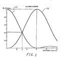
- FIG. 1 is a graph of the optical efficiency of a diffractive lens element.
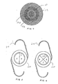
- FIG. 2 is a plan view of a preferred embodiment of a lens made in accordance with the present invention which has two diffractive elements divided into an annular and a circular zone.
- FIG. 3 is a plan view of another preferred embodiment of a lens made in accordance with the present invention which has a single diffractive element comprised of an annular zone.
- FIG. 4 is a plan view of a preferred embodiment of the present invention which has two diffractive elements each divided into two zones.
- FIG. 5 is a plan view of an intraocular lens made in accordance with the present invention which has a far vision zone and a near vision zone defined by bisecting the lens.
- FIG. 6 is a plan view of an intraocular lens made in accordance with the present invention which has a far vision zone and a near vision zone defined by dividing the lens into quadrants.
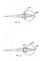
- FIG. 7 is a schematic representation of the passage of light through a bi-focal intraocular lens made in accordance with the present invention.
- FIG. 8 is a schematic representation of the passage of light through a bi-focal contact lens made in accordance with the present invention.
- the present invention presents numerous advantages over the prior designs discussed above.
- the present invention increases the overall aggregate efficiency of the lens. Ideally, 50% of the incident light is provided to each focal point. One image is created from distant objects and one image is created from near objects.
- the increased efficiency of the lenses of the present invention provide the maximum possible image contrast and resolution.
- the high efficiency diffraction zone has an optical efficiency of the greatest practical value, i.e., about 98%.
- a high efficiency diffraction grating is produced. Since about 98% of the light that passes through the diffractive zones will be focused on the retina for near objects and substantially all of the light that passes through the refractive zones will be focused on the retina for distant objects, improved multifocal vision is achieved.
- the present invention therefore overcomes the problem of unwanted light scattering caused by higher diffractive orders.
- lenses of the present invention have a higher potential efficiency than any known prior art design.
- the maximum theoretical efficiency available from a standard phase zone plate is about 81%.
- the intermittent diffractive/non-diffractive construction of the present invention has the potential to exhibit considerably higher efficiencies.
- the efficiency, of a diffractive lens element, as a percentage of transmitted light, is shown graphically in FIG. 1.
- the efficiency is plotted against the step height, in microns, on the lens surface for a silicone lens in water.
- a first plot line 50 depicts the efficiency of the 0th (zeroth) order diffraction.
- a second plot line 52 depicts the efficiency of the 1st (first) order diffraction.
- a step height equivalent to slightly more than 3 microns was chosen to evenly divide the first and zero order diffraction gradients, thereby causing about 40% of the light to be focused at a near focal length and about 40% of the light to be focused at a far focal length.
- the overall efficiency is thus about 80%.
- a step height of about 6 microns is chosen.
- almost 100% of the incident light is refracted at the first order.
- almost 100% of the light can be focused at either the near or the far focal lenght.
- FIG. 2 A plan view of an embodiment of a lens made in accordance with the present invention is depicted in FIG. 2.
- the lens may either be utilized in a contact lens or in an intraocular lens, therefore, unrelated features such as the haptics used to secure an intraocular lens in the eye are not shown.
- Bifocal vision is preferably achieved by providing a lens, such as a biconvex diffractive lens, which has a basic power and creating high efficiency diffractive zones 10,12 which provide additive diffractive power to the basic lens power.
- additive power refers to the arithmetic addition of the power of the lens elements, therefore, in some embodiments, the diffractive power may be negative and reduce the overall power of that zone.
- a circular diffractive zone 10 at approximately the center axis of the lens and dispose a second diffractive zone 12 in an annular spaced relationship with the first. Lying between the diffractive zones 10,12 are refractive zones 20,22, which possess the basic lens power only. Therefore, a portion of the incident light will fall upon the refractive zones 20,22 and provide focus at a first focal length. The optical efficiency of this zone will be the same as the optical efficiency of the basic lens, and if made to the highest commercial standards, will approach 100%. Another portion of the incident light will fall upon the diffractive zones 10,12 and also pass through the basic lens.
- the power of this portion of the lens will be the additive sum of the diffractive and refractive powers and will provide focus at a second focal length.
- the highest commercially available techniques for imparting a diffractive element are utilized to create the diffractive zones 10,12 thereby providing about 98% efficiency. As a result, the performance of the overall lens approaches 100% efficiency.
- lenses such as that depicted in FIG. 2 will have an overall diameter of about 7.0 millimeters (mm).
- the innermost diffractive zone 10 will have a diameter of about 1.72 mm
- the first refractive zone 20 will have an outside diameter of about 2.90 mm
- the next diffractive zone will have an outside diameter of about 4.60 mm
- the second refractive zone will have an outside diameter of about 7.00 mm.
- the design dimensions may be varied somewhat to achieve particular corrective effects. It will also be understood that the order of placement of the diffractive and refractive zones may be reversed, i.e., the central zone may be refractive, etc.
- FIG. 3 Another embodiment of a lens having similar properties to that shown in FIG. 2 is depicted in FIG. 3.
- the lens design shown has a centrally disposed first refractive zone 30, preferably of about 1.3 mm diameter if used in a 7.00 mm intraocular lens.
- a diffractive zone 40 Surrounding the first refractive zone 30 is a diffractive zone 40, which preferably has an outer diameter of about 3.36 mm.
- a second refractive zone 32 surrounds the refractive zone 40 and has an outer diameter of about 7.00 mm.
- FIG. 4 an embodiment of a high efficiency lens utilizing both diffractive and refractive elements over its entire surface to achieve bifocal vision is shown.
- the lens depicted in FIG. 1 has two zones of a first diffractive power 110,112 for distance vision and two zones of a second diffractive power 120,122 for near vision.
- the layout of the zones shown places the zones in a series of annular rings, it should be understood that numerous other layouts are comprehended by the present invention.
- the number of zones may be expanded or reduced.
- two zones of different diffractive powers are placed in an additive manner relative to a lens having a basic power to achieve multiple focal points.
- the layout, shape and relative size of the zones is dependent upon the specific correction required.
- a lens preferably provides a basic refractive power of about 10 diopters, achieved using a bi-convex lens or other lens designs known to those of ordinary skill.
- An additional 10 diopters of a first diffractive power is added by two diffractive zones 110,112, thereby providing a total power of 20 diopters for distance vision.
- Two near vision diffractive zones 120,122 which have a second diffractive power of about 14 diopters are also provided, resulting in a total near vision power of 24 diopters.
- each lens has near vision N and far vision F zones.
- either the near or the far zone may comprise a high efficiency diffractive element while the other zone comprises a refractive element of the basic lens.
- both the near and far zones will comprise diffractive elements, each respectively of a different diffractive power.
- the lenses depicted in FIGS. 5-6 also illustrate further variations of the geometries of the zones of different focal lengths created on the basic lens. As shown in FIGS. 2-4, it will be desirable in certain instances to create one or more circular or annular diffractive zones. As shown in FIGS. 5-6, it is also possible to divide the lens diametrically in halves or quarters, alternating the near and far vision zones accordingly. As will be readily understood by those of ordinary skill, the same zone layouts depicted in FIGS. 2-6 may be applied to contact lenses and other forms of lenses and are not limited to intraocular lenses.
- FIG. 7 The operation of an intraocular lens 200 within the eye 250 is shown in FIG. 7.
- Light from a near object N is focused on the retina R by the near vision zone.
- Light from a far object F is focused on the retina R by the far vision zone of the lens. Therefore, all of the light both the near and far objects is focused by the near or far zone respectively, resulting in a nearly 100% efficient lens.
- FIG. 8 depicts a contact lens 100 made in accordance with the present invention disposed on the cornea of an eye 250.
- the patient wearing a corrective contact lens also has a natural crystalline lens 260 within the eye.
- the lenses discussed above may have a basic refractive power provided by the shape of the lens.
- the present invention may be applied to bi-convex or piano convex lenses, as well as to meniscus lenses, such as contact lenses.
Abstract
Description
- The present invention relates to multifocal lenses for correcting vision and, more specifically relates to bifocal lenses having at least one diffractive zone which is added to the basic refractive power of the lens.
- Ophthalmic lenses which have two or more distinct focal lengths are known. Such lenses have been used in the past as contact lenses which are disposed upon the surface of the eye, or as intraocular lenses (IOL's) which are surgically implanted to replace the natural crystalline lens after its removal during, e.g., cataract surgery. Diffractive lenses are well known within the field of optics generally, however they have as yet found only limited application to intraocular or contact lens design. Thus, although numerous designs have been disclosed for multifocal optics for use in contact or intraocular lenses, few have been found to be in any way practical.
- Lenses relying solely upon refraction have been disclosed. For example, U.S. Patent 4,636,211--Nielsen, et al. discloses a bifocal intraocular lens which has concentrically oriented near vision and far vision zones achieved by refraction, the central zone adapted for near vision and surrounded by a coaxial far vision zone. The lenses disclosed have either a piano-convex or bi-convex shape. U.S. Patent 4,813,955--Achatz et al. discloses a multifocal intraocular artificial ophthalmic lens divided into near range and far range zones disposed symmetrically about the lens axis which uses the refractive power of the lens material and its shape to achieve bi-focal vision.
- Designs of contact lenses which rely only upon the refractive properties of the Fresnel lens are also known. For example, U.S. Patent 4,162,122--Cohen discloses a zonal bifocal contact lens comprised of a concave spherical or aspherical posterior surface and a continuous anterior surface which is divided into concentric annular rings which are alternately inclined to the optical axis, corresponding to curvatures appropriate for the near and distant foci. The interfaces of the annular zones are continuous and do not create any steps or jumps on the anterior surface. Each zone consists of a refractive element only, the zones forming a smooth anterior surface.
- Lenses utilizing the combined properties of Fresnel lenses and Fresnel zone plates and which rely on the diffractive effects thereof are also known. U.S. Patent 4,210,391--Cohen discloses multifocal optical lenses which have their multifocal properties distributed throughout the lens. The lenses disclosed share the incident light between the focal points by using a zone plate and splitting the incident light into discrete "bundles" each directed to a particular focal point. The design utilizes elements of both a Fresnel lens and a Fresnel zone plate, relying on the fact that such optical elements are comprised of concentric rings or zones and thus provides lens designs having reduced diffractive and chromatic aberrations. U.S. Patent 4,338,005--Cohen also discloses a multifocal phase plate lens design which has multifocal properties distributed throughout the lens. The lens disclosed is comprised of concentric zones, the diameters of which are derived from the focal length desired and wavelength of light being focused. The performance of the lens is not degraded by the superposition of blurred images at the focal points. Also, U.S. Patent 4,340,283--Cohen discloses a multifocal zone plate construction suitable for use in optical system with multifocal requirements. A phase shift multifocal zone plate provides multiple foci by adjusting the zone plate spacings such that the zone plate foci coincide with multifocal Fresnel lens foci. The adjustment is obtained by ion implantation in certain sections of the lens, whereby the refractive index of the lens is altered in that section.
- Additionally, others have attempted to combine both refractive and diffractive powers to create multifocal lenses. U.S. Patent 4, 673, 697--Freeman discloses multifocal contact lenses utilizing diffraction and refraction by adding diffractive power to the basic refractive power of the lens. The diffractive power is provided by a series of concentric zones defined by surface discontinuities or refractive index changes. In a bifocal application, diffractive power is provided in addition to the basic refractive power of the lens, while maintaining the basic curvature of the front and rear surfaces. The diffractive zones deviate all of the incident light in the manner of a phase zone plate (Fresnel zone plate). The ′697 Freeman patent teaches that it is important to maintain the radius of curvature of the rear surface of the lens at a value which will maintain close conformance with the cornea. U.S. Patent 4,642,112--Freeman discloses bifocal artificial eye lenses which utilize a transmission hologram to provide diffractive power on a wavelength or amplitude selective basis in a manner which is additive to the basic refractive power of the lens.
- When a diffraction element is used to provide two separate focal lengths, the maximum theoretical efficiency results in about 40.5% of the incident light forming an image at each focal distance. Therefore, the overall total efficiency of the lens is about 81%. The remainder of the light (about 19%) is scattered into higher order diffraction patterns and thus degrades the image formed, rather than enhancing them. Therefore, it would be desireable to provide multifocal lenses which utilize both diffractive and refractive elements and which exhibit an overall total efficiency closer to an ideal 100%.
- It is therefore an object of the present invention to provide a highly efficient multifocal lens. Accordingly, the present invention provides increased efficiency multifocal lenses by using at least one diffractive zone located in a defined portion of the surface of a refractive lens. The lenses of a first embodiment of the present invention are thus divided into two areas, a first area of highly efficient diffractive power and a second area having essentially no diffractive power. Most preferably, the diffraction zones provide substantially 100% efficiency in the +1 diffractive order. The non-diffractive zones allow light to be transmitted without appreciable deviation due to diffraction. Most preferably, the zones are of about equal area, thereby causing about one-half of the incident light to focus at each of the two focal planes, resulting in an overall lens efficiency approaching 100%.
- In another preferred embodiment, lenses are provided which have two different diffractive elements disposed substantially across the entire lens surface. The two diffractive patterns are different in that they have different diffractive powers. Since the diffractive powers are additive to a basic lens power provided by the lens upon which the diffractive elements are disposed, a multifocal lens having adequate power and high efficiency is achieved. For example, highly efficient zones having diffractive powers of about 10 diopters and 14 diopters can be provided for distance and near vision respectively. These diffractive powers are additive to the refractive basic power of the lens upon which they are disposed, e.g., a 10 diopter biconvex lens. Thus, in this example, 20 diopters of optic power are provided for distance vision and 24 diopters are provided for near vision. Since the diffractive zones are preferably high efficiency diffractive elements, a bifocal lens is provided which approaches 100% efficiency.
- FIG. 1 is a graph of the optical efficiency of a diffractive lens element.
- FIG. 2 is a plan view of a preferred embodiment of a lens made in accordance with the present invention which has two diffractive elements divided into an annular and a circular zone.
- FIG. 3 is a plan view of another preferred embodiment of a lens made in accordance with the present invention which has a single diffractive element comprised of an annular zone.
- FIG. 4 is a plan view of a preferred embodiment of the present invention which has two diffractive elements each divided into two zones.
- FIG. 5 is a plan view of an intraocular lens made in accordance with the present invention which has a far vision zone and a near vision zone defined by bisecting the lens.
- FIG. 6 is a plan view of an intraocular lens made in accordance with the present invention which has a far vision zone and a near vision zone defined by dividing the lens into quadrants.
- FIG. 7 is a schematic representation of the passage of light through a bi-focal intraocular lens made in accordance with the present invention.
- FIG. 8 is a schematic representation of the passage of light through a bi-focal contact lens made in accordance with the present invention.
- The present invention presents numerous advantages over the prior designs discussed above. Primarily, the present invention increases the overall aggregate efficiency of the lens. Ideally, 50% of the incident light is provided to each focal point. One image is created from distant objects and one image is created from near objects. The increased efficiency of the lenses of the present invention provide the maximum possible image contrast and resolution. Preferably the high efficiency diffraction zone has an optical efficiency of the greatest practical value, i.e., about 98%. In a preferred embodiment, a high efficiency diffraction grating is produced. Since about 98% of the light that passes through the diffractive zones will be focused on the retina for near objects and substantially all of the light that passes through the refractive zones will be focused on the retina for distant objects, improved multifocal vision is achieved. The present invention therefore overcomes the problem of unwanted light scattering caused by higher diffractive orders. Thus, lenses of the present invention have a higher potential efficiency than any known prior art design.
- As set forth above, the maximum theoretical efficiency available from a standard phase zone plate is about 81%. The intermittent diffractive/non-diffractive construction of the present invention has the potential to exhibit considerably higher efficiencies. The efficiency, of a diffractive lens element, as a percentage of transmitted light, is shown graphically in FIG. 1. The efficiency is plotted against the step height, in microns, on the lens surface for a silicone lens in water. A
first plot line 50 depicts the efficiency of the 0th (zeroth) order diffraction. Asecond plot line 52 depicts the efficiency of the 1st (first) order diffraction. In the typical prior art lenses discussed above, a step height equivalent to slightly more than 3 microns was chosen to evenly divide the first and zero order diffraction gradients, thereby causing about 40% of the light to be focused at a near focal length and about 40% of the light to be focused at a far focal length. The overall efficiency is thus about 80%. However, in the lenses of the present invention, a step height of about 6 microns is chosen. As clearly seen in Fig. 1, at this step height, almost 100% of the incident light is refracted at the first order. Thus, almost 100% of the light can be focused at either the near or the far focal lenght. By providing alternating 100% efficiency sectors, some focused for near and some for far, a nearly 100% efficient lens is achieved. - A plan view of an embodiment of a lens made in accordance with the present invention is depicted in FIG. 2. The lens may either be utilized in a contact lens or in an intraocular lens, therefore, unrelated features such as the haptics used to secure an intraocular lens in the eye are not shown. Bifocal vision is preferably achieved by providing a lens, such as a biconvex diffractive lens, which has a basic power and creating high efficiency
diffractive zones - As shown, in one preferred arrangement it is desirable to place a
circular diffractive zone 10 at approximately the center axis of the lens and dispose asecond diffractive zone 12 in an annular spaced relationship with the first. Lying between thediffractive zones refractive zones refractive zones diffractive zones diffractive zones - In a typical intraocular lens application, lenses such as that depicted in FIG. 2 will have an overall diameter of about 7.0 millimeters (mm). Most preferably, the
innermost diffractive zone 10 will have a diameter of about 1.72 mm, the firstrefractive zone 20 will have an outside diameter of about 2.90 mm, the next diffractive zone will have an outside diameter of about 4.60 mm and the second refractive zone will have an outside diameter of about 7.00 mm. As will be understood by those of ordinary skill, the design dimensions may be varied somewhat to achieve particular corrective effects. It will also be understood that the order of placement of the diffractive and refractive zones may be reversed, i.e., the central zone may be refractive, etc. - Another embodiment of a lens having similar properties to that shown in FIG. 2 is depicted in FIG. 3. The lens design shown has a centrally disposed first refractive zone 30, preferably of about 1.3 mm diameter if used in a 7.00 mm intraocular lens. Surrounding the first refractive zone 30 is a
diffractive zone 40, which preferably has an outer diameter of about 3.36 mm. A secondrefractive zone 32 surrounds therefractive zone 40 and has an outer diameter of about 7.00 mm. As set forth above, in certain embodiments it may be desirable to alter the dimensions given or to reverse the arrangement of the zones. - Referring now to FIG. 4, an embodiment of a high efficiency lens utilizing both diffractive and refractive elements over its entire surface to achieve bifocal vision is shown. The lens depicted in FIG. 1 has two zones of a first diffractive power 110,112 for distance vision and two zones of a second diffractive power 120,122 for near vision. Although the layout of the zones shown places the zones in a series of annular rings, it should be understood that numerous other layouts are comprehended by the present invention. Also, as demonstrated with reference to FIGS. 2-3, the number of zones may be expanded or reduced. In this embodiment of the present invention, two zones of different diffractive powers are placed in an additive manner relative to a lens having a basic power to achieve multiple focal points. As will be readily understood by those of ordinary skill, the layout, shape and relative size of the zones is dependent upon the specific correction required.
- In a preferred embodiment of the lens depicted in FIG. 4, a lens preferably provides a basic refractive power of about 10 diopters, achieved using a bi-convex lens or other lens designs known to those of ordinary skill. An additional 10 diopters of a first diffractive power is added by two diffractive zones 110,112, thereby providing a total power of 20 diopters for distance vision. Two near vision diffractive zones 120,122 which have a second diffractive power of about 14 diopters are also provided, resulting in a total near vision power of 24 diopters.
- Referring now to FIGS. 5-6,
intraocular lenses 200 made in accordance with the present invention are shown. Thelenses 200 havehaptics 210 for holding the lens in place. As shown, each lens has near vision N and far vision F zones. In accordance with one aspect of the present invention, either the near or the far zone may comprise a high efficiency diffractive element while the other zone comprises a refractive element of the basic lens. Alternatively, as discussed with reference to FIG. 4, in certain embodiments of the present invention, both the near and far zones will comprise diffractive elements, each respectively of a different diffractive power. - The lenses depicted in FIGS. 5-6 also illustrate further variations of the geometries of the zones of different focal lengths created on the basic lens. As shown in FIGS. 2-4, it will be desirable in certain instances to create one or more circular or annular diffractive zones. As shown in FIGS. 5-6, it is also possible to divide the lens diametrically in halves or quarters, alternating the near and far vision zones accordingly. As will be readily understood by those of ordinary skill, the same zone layouts depicted in FIGS. 2-6 may be applied to contact lenses and other forms of lenses and are not limited to intraocular lenses.
- The operation of an
intraocular lens 200 within theeye 250 is shown in FIG. 7. Light from a near object N is focused on the retina R by the near vision zone. Light from a far object F is focused on the retina R by the far vision zone of the lens. Therefore, all of the light both the near and far objects is focused by the near or far zone respectively, resulting in a nearly 100% efficient lens. - Similarly, FIG. 8 depicts a
contact lens 100 made in accordance with the present invention disposed on the cornea of aneye 250. Unlike the example of FIG. 7, the patient wearing a corrective contact lens also has a naturalcrystalline lens 260 within the eye. - As will be understood by those of ordinary skill the lenses discussed above may have a basic refractive power provided by the shape of the lens. The present invention may be applied to bi-convex or piano convex lenses, as well as to meniscus lenses, such as contact lenses.
- Although certain embodiments of the present invention have be set forth in detail, these examples are not meant to be limiting. Numerous other embodiments and variations to the embodiments set forth will immediately present themselves to those of ordinary skill. Accordingly, reference should be made to the appended claims in order to determine the scope of the present Invention.
Claims (33)
- A multifocal lens for correcting vision comprising:
a basic lens element having a basic lens power and a basic focal length; and
one or more diffractive elements covering one or more zones of said basic lens element and having a diffractive power,
whereby a portion of the light travelling through said lens is focused at said basic focal length by said basic lens power, and another portion of the light traveling through said lens is focused at a different focal length by the combined power of said basic lens element and said diffractive elements. - The lens of claim 1, wherein said lens is a contact lens.
- The lens of claim 1, wherein said lens is an intraocular lens.
- The lens of claim 1, wherein said basic power is provided by refraction.
- The lens of claim 4, wherein said basic lens comprises a biconvex lens.
- The lens of claim 4, wherein said basic lens element comprises a meniscus lens.
- The lens of claim 4, wherein said basic lens element comprises a piano-convex lens.
- The lens of claim 1, wherein said diffractive zones are arrayed in a substantially annular pattern.
- The lens of claim 1, wherein said diffractive zones are arranged as alternate semi-circular areas.
- The lens of claim 1, wherein said diffractive zones are arrayed as alternating quarter circular areas.
- The lens of claim 8, wherein said diffractive element comprises an annular zone having an inner diameter greater than zero and an outer diameter less than diameter of said lens.
- The lens of claim 11, wherein the inner diameter of said diffractive element is about 1.30 millimeters and the outer diameter is about 3.36 millimeters.
- The lens of claim 8, wherein said diffractive element comprises a circular zone disposed at about the geometric center of the lens and a annular zone having an inner diameter greater than zero and an outer diameter less than the diameter of said lens.
- The lens of claim 13, wherein the diameter of said circular zone is about 1.72 millimeters, and the inner diameter of said diffractive element is about 2.90 millimeters and the outer diameter is about 4.60 millimeters.
- The lens of claim 1, wherein said diffractive zones have a diffractive power of greater than about 2 diopters.
- The lens of claim 1, wherein the optical efficiency of said lens is greater than about 85%.
- The lens of claim 16, wherein the optical efficiency of said lens is about 100%.
- The lens of claim 1, wherein said diffractive element comprise Fresnel zone plate elements.
- The lens of claim 1, wherein said diffractive element comprise holographic elements.
- A multifocal lens for correcting vision comprising:
a basic lens element having a basic lens power and a basic focal length;
one or more first diffractive elements covering one or more zones of said basic lens element and having a first diffractive power; and
one or more second diffractive elements covering one or more zones of said basic lens element and having a second diffractive power,
whereby a first portion of the light travelling through said lens is focused at a first focal length by the combined power of said basic lens element and said first diffractive elements, and another portion of the light traveling through said lens is focused at a second focal length by the combined power of said basic lens element and said second diffractive elements. - The lens of claim 20, wherein said lens is a contact lens.
- The lens of claim 20, wherein said lens is an intraocular lens.
- The lens of claim 20, wherein said basic power is provided by refraction.
- The lens of claim 23, wherein said basic lens element comprises a biconvex lens.
- The lens of claim 23, wherein said basic lens element comprises a meniscus lens.
- The lens of claim 23, wherein said basic lens element comprises a piano-convex lens.
- The lens of claim 20, wherein said diffractive zones are arrayed in a substantially annular pattern.
- The lens of claim 20, wherein said diffractive zones are arranged as alternate semi-circular areas.
- The lens of claim 20, wherein said diffractive zones are arrayed as alternating quarter circular areas.
- The lens of claim 27, wherein said diffractive element comprises an annular zone having an inner diameter greater than zero and an outer diameter less than the diameter of said lens.
- The lens of claim 20, wherein said diffractive element comprises a circular zone disposed at about the geometric center of the lens and a annular zone having an inner diameter greater than zero and an outer diameter less than the diameter of said lens.
- The lens of claim 20, wherein said diffractive elements are of an optical efficiency greater than about 85%.
- The lens of claim 20, wherein said diffractive elements are of an optical efficiency of about 100%.
Applications Claiming Priority (2)
| Application Number | Priority Date | Filing Date | Title |
|---|---|---|---|
| US523146 | 1983-08-15 | ||
| US07/523,146 US5096285A (en) | 1990-05-14 | 1990-05-14 | Multifocal multizone diffractive ophthalmic lenses |
Publications (3)
| Publication Number | Publication Date |
|---|---|
| EP0457553A2 true EP0457553A2 (en) | 1991-11-21 |
| EP0457553A3 EP0457553A3 (en) | 1992-06-10 |
| EP0457553B1 EP0457553B1 (en) | 1999-01-27 |
Family
ID=24083841
Family Applications (1)
| Application Number | Title | Priority Date | Filing Date |
|---|---|---|---|
| EP91304322A Expired - Lifetime EP0457553B1 (en) | 1990-05-14 | 1991-05-14 | Multifocal multizone diffractive ophthalmic lenses |
Country Status (12)
| Country | Link |
|---|---|
| US (1) | US5096285A (en) |
| EP (1) | EP0457553B1 (en) |
| KR (1) | KR100207164B1 (en) |
| AU (1) | AU662291B2 (en) |
| DE (1) | DE69130812T2 (en) |
| ES (1) | ES2131045T3 (en) |
| IE (1) | IE911639A1 (en) |
| MX (1) | MX174633B (en) |
| MY (1) | MY106155A (en) |
| NZ (1) | NZ238077A (en) |
| PT (1) | PT97656A (en) |
| ZA (1) | ZA913611B (en) |
Cited By (64)
| Publication number | Priority date | Publication date | Assignee | Title |
|---|---|---|---|---|
| WO1992022264A1 (en) * | 1991-06-18 | 1992-12-23 | Allergan, Inc. | Multifocal ophthalmic lens |
| EP0610055A2 (en) * | 1993-02-01 | 1994-08-10 | Matsushita Electric Industrial Co., Ltd. | Compound objective lens having two focal points and apparatus using the lens |
| EP0681711A4 (en) * | 1993-01-27 | 1995-07-26 | Pilkington Barnes Hind Inc | Multifocal contact lens. |
| US5549670A (en) * | 1995-05-09 | 1996-08-27 | Allergan, Inc. | IOL for reducing secondary opacification |
| EP0785543A3 (en) * | 1996-01-19 | 1997-07-30 | Nec Corporation | Condenser lens for optical disks |
| WO1997033277A1 (en) * | 1996-03-08 | 1997-09-12 | Philips Electronics N.V. | Objective lens and scanning device using such an objective lens |
| US5693094A (en) * | 1995-05-09 | 1997-12-02 | Allergan | IOL for reducing secondary opacification |
| EP0838812A2 (en) * | 1996-10-23 | 1998-04-29 | Konica Corporation | Method for recording/reproducing on/from an optical information recording medium, optical pickup apparatus, objective lens and design method of objective lens |
| US5748282A (en) * | 1993-01-27 | 1998-05-05 | Pilkington Barnes Hind, Inc. | Multifocal contact lens |
| US5815293A (en) * | 1993-02-01 | 1998-09-29 | Matsushita Electric Industrial Co., Ltd. | Compound objective lens having two focal points |
| WO1998053360A1 (en) * | 1997-05-23 | 1998-11-26 | Aspect Vision Care Ltd. | Decentered bifocal contact lenses |
| EP0938016A1 (en) * | 1997-07-14 | 1999-08-25 | Seiko Epson Corporation | Contact lens |
| US6116735A (en) * | 1997-07-14 | 2000-09-12 | Seiko Epson Corporation | Contact lens |
| US6162249A (en) * | 1998-05-29 | 2000-12-19 | Allergan | IOI for inhibiting cell growth and reducing glare |
| EP1173790A2 (en) * | 1999-03-01 | 2002-01-23 | Boston Innovative Optics, Inc. | System and method for increasing the depth of focus of the human eye |
| EP0806039B1 (en) * | 1995-08-30 | 2002-05-15 | Samsung Electronics Co., Ltd. | Lens device and an optical pickup apparatus using the lens device |
| US6468306B1 (en) | 1998-05-29 | 2002-10-22 | Advanced Medical Optics, Inc | IOL for inhibiting cell growth and reducing glare |
| US6648741B2 (en) | 2002-03-14 | 2003-11-18 | Advanced Medical Optics, Inc. | Apparatus for protecting the edge geometry of an intraocular lens during glass bead polishing process |
| US6884262B2 (en) | 1998-05-29 | 2005-04-26 | Advanced Medical Optics, Inc. | Enhanced intraocular lens for reducing glare |
| EP1634115A2 (en) * | 2003-06-16 | 2006-03-15 | Apollo Optical Systems LLC | Bifocal multiorder diffractive lenses for vision correction |
| USRE39025E1 (en) | 1995-08-30 | 2006-03-21 | Samsung Electronics Co., Ltd. | Lens device including a light controlling mechanism and an optical pickup apparatus using a lens device |
| US7063422B2 (en) | 2003-04-16 | 2006-06-20 | Novartis Ag | Multifocal ophthalmic lens |
| EP1889115A1 (en) * | 2005-05-12 | 2008-02-20 | Valdemar Portney | Aspherical diffractive ophthalmic lens |
| ES2311315A1 (en) * | 2005-08-04 | 2009-02-01 | Universitat De Valencia | Diffactive lens of fibonacci. (Machine-translation by Google Translate, not legally binding) |
| EP2045648A1 (en) * | 2007-10-02 | 2009-04-08 | Alcon, Inc. | Zonal diffractive multifocal intraocular lenses |
| EP2113226A1 (en) * | 2002-11-29 | 2009-11-04 | AMO Groningen B.V. | Multifocal ophthalmic lens |
| WO2011075651A1 (en) * | 2009-12-18 | 2011-06-23 | Abbott Medical Optics Inc. | Limited echelette lens, systems and methods |
| US7976577B2 (en) | 2005-04-14 | 2011-07-12 | Acufocus, Inc. | Corneal optic formed of degradation resistant polymer |
| US8079706B2 (en) | 2003-06-17 | 2011-12-20 | Acufocus, Inc. | Method and apparatus for aligning a mask with the visual axis of an eye |
| USD656526S1 (en) | 2009-11-10 | 2012-03-27 | Acufocus, Inc. | Ocular mask |
| US8460374B2 (en) | 2003-05-28 | 2013-06-11 | Acufocus, Inc. | Mask configured to maintain nutrient transport without producing visible diffraction patterns |
| US8862447B2 (en) | 2010-04-30 | 2014-10-14 | Amo Groningen B.V. | Apparatus, system and method for predictive modeling to design, evaluate and optimize ophthalmic lenses |
| US8894204B2 (en) | 2010-12-17 | 2014-11-25 | Abbott Medical Optics Inc. | Ophthalmic lens, systems and methods having at least one rotationally asymmetric diffractive structure |
| US8906089B2 (en) | 2002-11-29 | 2014-12-09 | Amo Groningen B.V. | Multifocal ophthalmic lens |
| US8974526B2 (en) | 2007-08-27 | 2015-03-10 | Amo Groningen B.V. | Multizonal lens with extended depth of focus |
| US9204962B2 (en) | 2013-03-13 | 2015-12-08 | Acufocus, Inc. | In situ adjustable optical mask |
| US9216080B2 (en) | 2007-08-27 | 2015-12-22 | Amo Groningen B.V. | Toric lens with decreased sensitivity to cylinder power and rotation and method of using the same |
| US9259308B2 (en) | 2003-12-09 | 2016-02-16 | Abbott Medical Optics Inc. | Foldable intraocular lens and method of making |
| US9335563B2 (en) | 2012-08-31 | 2016-05-10 | Amo Groningen B.V. | Multi-ring lens, systems and methods for extended depth of focus |
| WO2016092285A1 (en) * | 2014-12-09 | 2016-06-16 | The Technology Partnership Plc | Display system |
| US9427922B2 (en) | 2013-03-14 | 2016-08-30 | Acufocus, Inc. | Process for manufacturing an intraocular lens with an embedded mask |
| US9454018B2 (en) | 2008-02-15 | 2016-09-27 | Amo Groningen B.V. | System, ophthalmic lens, and method for extending depth of focus |
| US9456894B2 (en) | 2008-02-21 | 2016-10-04 | Abbott Medical Optics Inc. | Toric intraocular lens with modified power characteristics |
| US9545303B2 (en) | 2011-12-02 | 2017-01-17 | Acufocus, Inc. | Ocular mask having selective spectral transmission |
| US9561098B2 (en) | 2013-03-11 | 2017-02-07 | Abbott Medical Optics Inc. | Intraocular lens that matches an image surface to a retinal shape, and method of designing same |
| US9579192B2 (en) | 2014-03-10 | 2017-02-28 | Amo Groningen B.V. | Dual-optic intraocular lens that improves overall vision where there is a local loss of retinal function |
| US9931200B2 (en) | 2010-12-17 | 2018-04-03 | Amo Groningen B.V. | Ophthalmic devices, systems, and methods for optimizing peripheral vision |
| US10010407B2 (en) | 2014-04-21 | 2018-07-03 | Amo Groningen B.V. | Ophthalmic devices that improve peripheral vision |
| US10588738B2 (en) | 2016-03-11 | 2020-03-17 | Amo Groningen B.V. | Intraocular lenses that improve peripheral vision |
| US10624735B2 (en) | 2016-02-09 | 2020-04-21 | Amo Groningen B.V. | Progressive power intraocular lens, and methods of use and manufacture |
| US10649234B2 (en) | 2016-03-23 | 2020-05-12 | Johnson & Johnson Surgical Vision, Inc. | Ophthalmic apparatus with corrective meridians having extended tolerance band |
| US10646329B2 (en) | 2016-03-23 | 2020-05-12 | Johnson & Johnson Surgical Vision, Inc. | Ophthalmic apparatus with corrective meridians having extended tolerance band |
| US10653556B2 (en) | 2012-12-04 | 2020-05-19 | Amo Groningen B.V. | Lenses, systems and methods for providing binocular customized treatments to correct presbyopia |
| US10739227B2 (en) | 2017-03-23 | 2020-08-11 | Johnson & Johnson Surgical Vision, Inc. | Methods and systems for measuring image quality |
| US11013594B2 (en) | 2016-10-25 | 2021-05-25 | Amo Groningen B.V. | Realistic eye models to design and evaluate intraocular lenses for a large field of view |
| US11096778B2 (en) | 2016-04-19 | 2021-08-24 | Amo Groningen B.V. | Ophthalmic devices, system and methods that improve peripheral vision |
| US11156853B2 (en) | 2017-06-28 | 2021-10-26 | Amo Groningen B.V. | Extended range and related intraocular lenses for presbyopia treatment |
| US11262598B2 (en) | 2017-06-28 | 2022-03-01 | Amo Groningen, B.V. | Diffractive lenses and related intraocular lenses for presbyopia treatment |
| US11282605B2 (en) | 2017-11-30 | 2022-03-22 | Amo Groningen B.V. | Intraocular lenses that improve post-surgical spectacle independent and methods of manufacturing thereof |
| US11327210B2 (en) | 2017-06-30 | 2022-05-10 | Amo Groningen B.V. | Non-repeating echelettes and related intraocular lenses for presbyopia treatment |
| US11497599B2 (en) | 2017-03-17 | 2022-11-15 | Amo Groningen B.V. | Diffractive intraocular lenses for extended range of vision |
| US11506914B2 (en) | 2010-12-01 | 2022-11-22 | Amo Groningen B.V. | Multifocal lens having an optical add power progression, and a system and method of providing same |
| US11523897B2 (en) | 2017-06-23 | 2022-12-13 | Amo Groningen B.V. | Intraocular lenses for presbyopia treatment |
| US11844689B2 (en) | 2019-12-30 | 2023-12-19 | Amo Groningen B.V. | Achromatic lenses and lenses having diffractive profiles with irregular width for vision treatment |
Families Citing this family (83)
| Publication number | Priority date | Publication date | Assignee | Title |
|---|---|---|---|---|
| US5198844A (en) * | 1991-07-10 | 1993-03-30 | Johnson & Johnson Vision Products, Inc. | Segmented multifocal contact lens |
| US5512220A (en) * | 1991-07-10 | 1996-04-30 | Johnson & Johnson Vision Products, Inc. | Method of making a clear axis, segmented multifocal ophthalmic lens |
| EP0563783B1 (en) * | 1992-04-03 | 1996-11-13 | Chiron Adatomed Pharmazeutische und Medizintechnische Gesellschaft mbH | Intraocular lens set |
| US5344447A (en) * | 1992-11-12 | 1994-09-06 | Massachusetts Institute Of Technology | Diffractive trifocal intra-ocular lens design |
| US5702440A (en) * | 1996-01-26 | 1997-12-30 | Allergan | Multifocal ophthalmic lens for dim-lighting conditions |
| US5683457A (en) * | 1996-05-09 | 1997-11-04 | Prism Opthalmics, L.L.C. | Prismatic intraocular lenses and related method of using such lenses to restore vision in patients with central field loss |
| US5888122A (en) * | 1997-04-10 | 1999-03-30 | Prism Ophthalmics, L.L.C. | Method for manufacturing an intraocular lens |
| US6231603B1 (en) | 1998-11-10 | 2001-05-15 | Allergan Sales, Inc. | Accommodating multifocal intraocular lens |
| US6616692B1 (en) | 1999-04-30 | 2003-09-09 | Advanced Medical Optics, Inc. | Intraocular lens combinations |
| US6790232B1 (en) | 1999-04-30 | 2004-09-14 | Advanced Medical Optics, Inc. | Multifocal phakic intraocular lens |
| US20060238702A1 (en) * | 1999-04-30 | 2006-10-26 | Advanced Medical Optics, Inc. | Ophthalmic lens combinations |
| US6406494B1 (en) | 1999-04-30 | 2002-06-18 | Allergan Sales, Inc. | Moveable intraocular lens |
| US20030060881A1 (en) * | 1999-04-30 | 2003-03-27 | Advanced Medical Optics, Inc. | Intraocular lens combinations |
| US6599317B1 (en) | 1999-09-17 | 2003-07-29 | Advanced Medical Optics, Inc. | Intraocular lens with a translational zone |
| US6645246B1 (en) | 1999-09-17 | 2003-11-11 | Advanced Medical Optics, Inc. | Intraocular lens with surrounded lens zone |
| US6551354B1 (en) | 2000-03-09 | 2003-04-22 | Advanced Medical Optics, Inc. | Accommodating intraocular lens |
| US6547822B1 (en) | 2000-05-03 | 2003-04-15 | Advanced Medical Optics, Inc. | Opthalmic lens systems |
| US6554859B1 (en) | 2000-05-03 | 2003-04-29 | Advanced Medical Optics, Inc. | Accommodating, reduced ADD power multifocal intraocular lenses |
| US6537317B1 (en) | 2000-05-03 | 2003-03-25 | Advanced Medical Optics, Inc. | Binocular lens systems |
| US6660035B1 (en) | 2000-08-02 | 2003-12-09 | Advanced Medical Optics, Inc. | Accommodating intraocular lens with suspension structure |
| US6695880B1 (en) * | 2000-10-24 | 2004-02-24 | Johnson & Johnson Vision Care, Inc. | Intraocular lenses and methods for their manufacture |
| US6643065B1 (en) | 2001-01-18 | 2003-11-04 | Donn Michael Silberman | Variable spacing diffraction grating |
| US8062361B2 (en) | 2001-01-25 | 2011-11-22 | Visiogen, Inc. | Accommodating intraocular lens system with aberration-enhanced performance |
| US7780729B2 (en) | 2004-04-16 | 2010-08-24 | Visiogen, Inc. | Intraocular lens |
| US20030078658A1 (en) * | 2001-01-25 | 2003-04-24 | Gholam-Reza Zadno-Azizi | Single-piece accomodating intraocular lens system |
| US20030078657A1 (en) * | 2001-01-25 | 2003-04-24 | Gholam-Reza Zadno-Azizi | Materials for use in accommodating intraocular lens system |
| US7087080B2 (en) * | 2001-01-25 | 2006-08-08 | Visiogen, Inc. | Materials for use in intraocular lens system |
| US20120016349A1 (en) | 2001-01-29 | 2012-01-19 | Amo Development, Llc. | Hybrid ophthalmic interface apparatus and method of interfacing a surgical laser with an eye |
| US6576012B2 (en) | 2001-03-28 | 2003-06-10 | Advanced Medical Optics, Inc. | Binocular lens systems |
| US6638305B2 (en) | 2001-05-15 | 2003-10-28 | Advanced Medical Optics, Inc. | Monofocal intraocular lens convertible to multifocal intraocular lens |
| US7150759B2 (en) * | 2002-01-14 | 2006-12-19 | Advanced Medical Optics, Inc. | Multi-mechanistic accommodating intraocular lenses |
| US7326246B2 (en) * | 2002-01-14 | 2008-02-05 | Advanced Medical Optics, Inc. | Accommodating intraocular lens with elongated suspension structure |
| US7763069B2 (en) | 2002-01-14 | 2010-07-27 | Abbott Medical Optics Inc. | Accommodating intraocular lens with outer support structure |
| AU2003210534A1 (en) * | 2002-01-14 | 2003-07-30 | Advanced Medical Optics, Inc. | Accommodating intraocular lens with integral capsular bag ring |
| US6972033B2 (en) * | 2002-08-26 | 2005-12-06 | Advanced Medical Optics, Inc. | Accommodating intraocular lens assembly with multi-functional capsular bag ring |
| US6851803B2 (en) * | 2002-10-24 | 2005-02-08 | C. Benjamin Wooley | Ophthalmic lenses with reduced chromatic blur |
| US20040082993A1 (en) | 2002-10-25 | 2004-04-29 | Randall Woods | Capsular intraocular lens implant having a refractive liquid therein |
| US7662180B2 (en) | 2002-12-05 | 2010-02-16 | Abbott Medical Optics Inc. | Accommodating intraocular lens and method of manufacture thereof |
| US20050131535A1 (en) * | 2003-12-15 | 2005-06-16 | Randall Woods | Intraocular lens implant having posterior bendable optic |
| US7025456B2 (en) * | 2004-08-20 | 2006-04-11 | Apollo Optical Systems, Llc | Diffractive lenses for vision correction |
| US7156516B2 (en) * | 2004-08-20 | 2007-01-02 | Apollo Optical Systems Llc | Diffractive lenses for vision correction |
| US7506983B2 (en) | 2004-09-30 | 2009-03-24 | The Hong Kong Polytechnic University | Method of optical treatment |
| US7922326B2 (en) | 2005-10-25 | 2011-04-12 | Abbott Medical Optics Inc. | Ophthalmic lens with multiple phase plates |
| JP4926068B2 (en) * | 2004-10-25 | 2012-05-09 | アボット・メディカル・オプティクス・インコーポレイテッド | Ophthalmic lens having a plurality of phase plates |
| US20070171362A1 (en) * | 2004-12-01 | 2007-07-26 | Simpson Michael J | Truncated diffractive intraocular lenses |
| WO2007019389A1 (en) * | 2005-08-05 | 2007-02-15 | Visiogen, Inc. | Accommodating diffractive intraocular lens |
| US9636213B2 (en) | 2005-09-30 | 2017-05-02 | Abbott Medical Optics Inc. | Deformable intraocular lenses and lens systems |
| US20070168027A1 (en) * | 2006-01-13 | 2007-07-19 | Brady Daniel G | Accommodating diffractive intraocular lens |
| AR062067A1 (en) | 2006-07-17 | 2008-10-15 | Novartis Ag | TORICAS CONTACT LENSES WITH CONTROLLED OPTICAL POWER PROFILE |
| AU2007338100B2 (en) | 2006-12-22 | 2014-01-30 | Amo Groningen Bv | Accommodating intraocular lens, lens system and frame therefor |
| US7713299B2 (en) * | 2006-12-29 | 2010-05-11 | Abbott Medical Optics Inc. | Haptic for accommodating intraocular lens |
| WO2008083283A2 (en) | 2006-12-29 | 2008-07-10 | Advanced Medical Optics, Inc. | Multifocal accommodating intraocular lens |
| US20080161914A1 (en) | 2006-12-29 | 2008-07-03 | Advanced Medical Optics, Inc. | Pre-stressed haptic for accommodating intraocular lens |
| US20080300679A1 (en) * | 2007-06-01 | 2008-12-04 | Altmann Griffith E | Diffractive Intraocular Lens |
| US20090228101A1 (en) * | 2007-07-05 | 2009-09-10 | Visiogen, Inc. | Intraocular lens with post-implantation adjustment capabilities |
| US8740978B2 (en) * | 2007-08-27 | 2014-06-03 | Amo Regional Holdings | Intraocular lens having extended depth of focus |
| US8747466B2 (en) * | 2007-08-27 | 2014-06-10 | Amo Groningen, B.V. | Intraocular lens having extended depth of focus |
| US20090062911A1 (en) * | 2007-08-27 | 2009-03-05 | Amo Groningen Bv | Multizonal lens with extended depth of focus |
| US8034108B2 (en) * | 2008-03-28 | 2011-10-11 | Abbott Medical Optics Inc. | Intraocular lens having a haptic that includes a cap |
| US8231219B2 (en) | 2008-04-24 | 2012-07-31 | Amo Groningen B.V. | Diffractive lens exhibiting enhanced optical performance |
| US7871162B2 (en) * | 2008-04-24 | 2011-01-18 | Amo Groningen B.V. | Diffractive multifocal lens having radially varying light distribution |
| US8520309B2 (en) | 2008-09-04 | 2013-08-27 | Innovega Inc. | Method and apparatus to process display and non-display information |
| US8922898B2 (en) | 2008-09-04 | 2014-12-30 | Innovega Inc. | Molded lens with nanofilaments and related methods |
| US8142016B2 (en) | 2008-09-04 | 2012-03-27 | Innovega, Inc. | Method and apparatus for constructing a contact lens with optics |
| US8734511B2 (en) * | 2008-10-20 | 2014-05-27 | Amo Groningen, B.V. | Multifocal intraocular lens |
| US8292953B2 (en) * | 2008-10-20 | 2012-10-23 | Amo Groningen B.V. | Multifocal intraocular lens |
| US8771348B2 (en) * | 2008-10-20 | 2014-07-08 | Abbott Medical Optics Inc. | Multifocal intraocular lens |
| US8216307B2 (en) * | 2008-12-19 | 2012-07-10 | Novartis Ag | Radially segmented apodized diffractive multifocal design for ocular implant |
| AU2010266020B2 (en) | 2009-06-26 | 2015-03-26 | Johnson & Johnson Surgical Vision, Inc. | Accommodating intraocular lenses |
| CA2770074C (en) | 2009-08-03 | 2017-09-05 | Abbott Medical Optics Inc. | Intraocular lens for providing accomodative vision |
| EP2464311B1 (en) | 2009-08-13 | 2017-11-15 | AcuFocus, Inc. | Masked intraocular implants and lenses |
| JP5763656B2 (en) * | 2009-10-26 | 2015-08-12 | ノバルティス アーゲー | Phase-shifted central and far diffractive design for ocular implants |
| US20120140166A1 (en) | 2010-12-07 | 2012-06-07 | Abbott Medical Optics Inc. | Pupil dependent diffractive lens for near, intermediate, and far vision |
| US10656437B2 (en) | 2011-12-21 | 2020-05-19 | Brien Holden Vision Institute Limited | Optical lens with halo reduction |
| US9084674B2 (en) | 2012-05-02 | 2015-07-21 | Abbott Medical Optics Inc. | Intraocular lens with shape changing capability to provide enhanced accomodation and visual acuity |
| US9995946B2 (en) * | 2014-06-13 | 2018-06-12 | Pegavision Corporation | Toric lens |
| JP6500484B2 (en) * | 2015-02-19 | 2019-04-17 | 株式会社ニデック | Multifocal intraocular lens |
| US11083566B2 (en) | 2016-02-29 | 2021-08-10 | Alcon Inc. | Ophthalmic lens having an extended depth of focus |
| ES2803225T3 (en) * | 2017-07-26 | 2021-01-25 | Vsy Biyoteknoloji Ve Ilac Sanayi Anonim Sirketi | Ophthalmic multifocal diffractive lens |
| US11707354B2 (en) | 2017-09-11 | 2023-07-25 | Amo Groningen B.V. | Methods and apparatuses to increase intraocular lenses positional stability |
| CN108646332B (en) * | 2018-06-11 | 2020-06-16 | 中南大学 | Novel zone plate construction method and zone plate manufactured by same |
| US11886046B2 (en) | 2019-12-30 | 2024-01-30 | Amo Groningen B.V. | Multi-region refractive lenses for vision treatment |
| US20230032140A1 (en) * | 2021-07-28 | 2023-02-02 | Coopervision International Limited | Methods of increased contact lens rotation and related contact lenses |
Citations (4)
| Publication number | Priority date | Publication date | Assignee | Title |
|---|---|---|---|---|
| GB2183246A (en) * | 1985-11-25 | 1987-06-03 | Donald James Highgate | Improvements to hydrophilic materials |
| EP0316162A2 (en) * | 1987-11-12 | 1989-05-17 | Allen L. Dr. Cohen | Multifocal ophthalmic lens |
| EP0317168A2 (en) * | 1987-11-12 | 1989-05-24 | Allen L. Dr. Cohen | Multifocal diffractive ophthalmic lens |
| EP0343067A1 (en) * | 1988-05-19 | 1989-11-23 | ESSILOR INTERNATIONAL Compagnie Générale d'Optique | Diffractive lens with a composite profile |
Family Cites Families (10)
| Publication number | Priority date | Publication date | Assignee | Title |
|---|---|---|---|---|
| US4162122A (en) * | 1977-09-14 | 1979-07-24 | Cohen Allen L | Zonal bifocal contact lens |
| US4210391A (en) * | 1977-09-14 | 1980-07-01 | Cohen Allen L | Multifocal zone plate |
| US4338005A (en) * | 1978-12-18 | 1982-07-06 | Cohen Allen L | Multifocal phase place |
| US4340283A (en) * | 1978-12-18 | 1982-07-20 | Cohen Allen L | Phase shift multifocal zone plate |
| DE3265356D1 (en) * | 1981-04-29 | 1985-09-19 | Pilkington Perkin Elmer Ltd | Artificial eye lenses |
| EP0109753B1 (en) * | 1982-10-27 | 1988-07-27 | Pilkington Plc | Bifocal contact lens comprising a plurality of concentric zones |
| DE3332313A1 (en) * | 1983-09-07 | 1985-04-04 | Titmus Eurocon Kontaktlinsen GmbH, 8750 Aschaffenburg | MULTIFOCAL, ESPECIALLY BIFOCAL, INTRAOCULAR ARTIFICIAL EYE LENS |
| US4636211A (en) * | 1984-03-13 | 1987-01-13 | Nielsen J Mchenry | Bifocal intra-ocular lens |
| US5056908A (en) * | 1987-11-12 | 1991-10-15 | Cohen Allen L | Optic zone phase channels |
| US4923296A (en) * | 1988-07-14 | 1990-05-08 | Erickson Paul M | Oriented simultaneous vision bifocal contact lenses or the like utilizing introaocular suppression of blur |
-
1990
- 1990-05-14 US US07/523,146 patent/US5096285A/en not_active Expired - Lifetime
-
1991
- 1991-05-07 NZ NZ238077A patent/NZ238077A/en unknown
- 1991-05-13 MY MYPI91000808A patent/MY106155A/en unknown
- 1991-05-13 IE IE163991A patent/IE911639A1/en unknown
- 1991-05-13 AU AU76494/91A patent/AU662291B2/en not_active Ceased
- 1991-05-13 ZA ZA913611A patent/ZA913611B/en unknown
- 1991-05-14 MX MX025774A patent/MX174633B/en unknown
- 1991-05-14 KR KR1019910007736A patent/KR100207164B1/en not_active IP Right Cessation
- 1991-05-14 EP EP91304322A patent/EP0457553B1/en not_active Expired - Lifetime
- 1991-05-14 ES ES91304322T patent/ES2131045T3/en not_active Expired - Lifetime
- 1991-05-14 PT PT97656A patent/PT97656A/en not_active Application Discontinuation
- 1991-05-14 DE DE69130812T patent/DE69130812T2/en not_active Expired - Fee Related
Patent Citations (4)
| Publication number | Priority date | Publication date | Assignee | Title |
|---|---|---|---|---|
| GB2183246A (en) * | 1985-11-25 | 1987-06-03 | Donald James Highgate | Improvements to hydrophilic materials |
| EP0316162A2 (en) * | 1987-11-12 | 1989-05-17 | Allen L. Dr. Cohen | Multifocal ophthalmic lens |
| EP0317168A2 (en) * | 1987-11-12 | 1989-05-24 | Allen L. Dr. Cohen | Multifocal diffractive ophthalmic lens |
| EP0343067A1 (en) * | 1988-05-19 | 1989-11-23 | ESSILOR INTERNATIONAL Compagnie Générale d'Optique | Diffractive lens with a composite profile |
Non-Patent Citations (1)
| Title |
|---|
| NEW SCIENTIST. 10 March 1990, LONDON GB page 39; HECHT: 'Dual Vision Lenses Give a Better View' * |
Cited By (146)
| Publication number | Priority date | Publication date | Assignee | Title |
|---|---|---|---|---|
| EP0766951A1 (en) * | 1991-06-18 | 1997-04-09 | Allergan, Inc | Multifocal ophthalmic lens |
| WO1992022264A1 (en) * | 1991-06-18 | 1992-12-23 | Allergan, Inc. | Multifocal ophthalmic lens |
| EP0681711A4 (en) * | 1993-01-27 | 1995-07-26 | Pilkington Barnes Hind Inc | Multifocal contact lens. |
| EP0681711A1 (en) * | 1993-01-27 | 1995-11-15 | Pilkington Barnes Hind, Inc. | Multifocal contact lens |
| US5748282A (en) * | 1993-01-27 | 1998-05-05 | Pilkington Barnes Hind, Inc. | Multifocal contact lens |
| US5446565A (en) * | 1993-02-01 | 1995-08-29 | Matsushita Electric Industrial Co., Ltd. | Compound objective lens having two focal points |
| EP0610055A3 (en) * | 1993-02-01 | 1995-01-11 | Matsushita Electric Ind Co Ltd | Compound objective lens having two focal points and apparatus using the lens. |
| USRE41455E1 (en) * | 1993-02-01 | 2010-07-27 | Panasonic Corporation | Objective lens for optical disks having different thicknesses |
| EP0610055A2 (en) * | 1993-02-01 | 1994-08-10 | Matsushita Electric Industrial Co., Ltd. | Compound objective lens having two focal points and apparatus using the lens |
| USRE38943E1 (en) * | 1993-02-01 | 2006-01-24 | Matsushita Electric Industrial Co., Ltd. | Compound objective lens for optical disks having different thicknesses |
| US5815293A (en) * | 1993-02-01 | 1998-09-29 | Matsushita Electric Industrial Co., Ltd. | Compound objective lens having two focal points |
| US6258123B1 (en) | 1995-05-09 | 2001-07-10 | Allergan | IOL for reducing secondary opacification |
| US5549670A (en) * | 1995-05-09 | 1996-08-27 | Allergan, Inc. | IOL for reducing secondary opacification |
| US5693094A (en) * | 1995-05-09 | 1997-12-02 | Allergan | IOL for reducing secondary opacification |
| US6656222B2 (en) | 1995-05-09 | 2003-12-02 | Advanced Medical Optics, Inc. | IOL for reducing secondary opacification |
| USRE39025E1 (en) | 1995-08-30 | 2006-03-21 | Samsung Electronics Co., Ltd. | Lens device including a light controlling mechanism and an optical pickup apparatus using a lens device |
| CN100412963C (en) * | 1995-08-30 | 2008-08-20 | 三星电子株式会社 | An optical head device using single lens |
| EP0806039B1 (en) * | 1995-08-30 | 2002-05-15 | Samsung Electronics Co., Ltd. | Lens device and an optical pickup apparatus using the lens device |
| US5835283A (en) * | 1996-01-19 | 1998-11-10 | Nec Corporation | Condenser lens for optical disks |
| EP0785543A3 (en) * | 1996-01-19 | 1997-07-30 | Nec Corporation | Condenser lens for optical disks |
| WO1997033277A1 (en) * | 1996-03-08 | 1997-09-12 | Philips Electronics N.V. | Objective lens and scanning device using such an objective lens |
| US6243349B1 (en) | 1996-10-23 | 2001-06-05 | Konica Corporation | Method for recording/reproducing optical information recording medium, optical pickup apparatus, objective lens and design method of objective lens |
| EP0838812A2 (en) * | 1996-10-23 | 1998-04-29 | Konica Corporation | Method for recording/reproducing on/from an optical information recording medium, optical pickup apparatus, objective lens and design method of objective lens |
| EP1103958A2 (en) * | 1996-10-23 | 2001-05-30 | Konica Corporation | Method for recording/reproducing optical information recording medium, optical pickup apparatus |
| US6061324A (en) * | 1996-10-23 | 2000-05-09 | Konica Corporation | Method for recording/reproducing optical information recording medium, optical pickup apparatus, objective lens and design method of objective lens |
| US6118749A (en) * | 1996-10-23 | 2000-09-12 | Konica Corporation | Method for recording/reproducing optical information recording medium, optical pickup apparatus, objective lens and design method of objective lens |
| EP1103958A3 (en) * | 1996-10-23 | 2004-10-06 | Konica Corporation | Method for recording/reproducing optical information recording medium, optical pickup apparatus |
| EP0838812A3 (en) * | 1996-10-23 | 1998-09-02 | Konica Corporation | Method for recording/reproducing on/from an optical information recording medium, optical pickup apparatus, objective lens and design method of objective lens |
| US6400672B2 (en) | 1996-10-23 | 2002-06-04 | Konica Corporation | Method for recording/reproducing optical information recording medium, optical pickup apparatus, objective lens and design method of objective lens |
| WO1998053360A1 (en) * | 1997-05-23 | 1998-11-26 | Aspect Vision Care Ltd. | Decentered bifocal contact lenses |
| EP0938016A4 (en) * | 1997-07-14 | 1999-10-27 | Seiko Epson Corp | Contact lens |
| US6116735A (en) * | 1997-07-14 | 2000-09-12 | Seiko Epson Corporation | Contact lens |
| EP0938016A1 (en) * | 1997-07-14 | 1999-08-25 | Seiko Epson Corporation | Contact lens |
| US6884262B2 (en) | 1998-05-29 | 2005-04-26 | Advanced Medical Optics, Inc. | Enhanced intraocular lens for reducing glare |
| US6162249A (en) * | 1998-05-29 | 2000-12-19 | Allergan | IOI for inhibiting cell growth and reducing glare |
| US9949822B2 (en) | 1998-05-29 | 2018-04-24 | Johnson & Johnson Surgical Vision, Inc. | Intraocular lens for inhibiting cell growth and reducing glare |
| US6468306B1 (en) | 1998-05-29 | 2002-10-22 | Advanced Medical Optics, Inc | IOL for inhibiting cell growth and reducing glare |
| EP1173790A2 (en) * | 1999-03-01 | 2002-01-23 | Boston Innovative Optics, Inc. | System and method for increasing the depth of focus of the human eye |
| US8343215B2 (en) | 1999-03-01 | 2013-01-01 | Acufocus, Inc. | System and method for increasing the depth of focus of the human eye |
| US8752958B2 (en) | 1999-03-01 | 2014-06-17 | Boston Innovative Optics, Inc. | System and method for increasing the depth of focus of the human eye |
| US6648741B2 (en) | 2002-03-14 | 2003-11-18 | Advanced Medical Optics, Inc. | Apparatus for protecting the edge geometry of an intraocular lens during glass bead polishing process |
| US9636214B2 (en) | 2002-11-29 | 2017-05-02 | Amo Groningen B.V. | Multifocal ophthalmic lens |
| EP2113226A1 (en) * | 2002-11-29 | 2009-11-04 | AMO Groningen B.V. | Multifocal ophthalmic lens |
| US8906089B2 (en) | 2002-11-29 | 2014-12-09 | Amo Groningen B.V. | Multifocal ophthalmic lens |
| US10085833B2 (en) | 2002-11-29 | 2018-10-02 | Amo Groningen B.V. | Multifocal ophthalmic lens |
| US7063422B2 (en) | 2003-04-16 | 2006-06-20 | Novartis Ag | Multifocal ophthalmic lens |
| US9138142B2 (en) | 2003-05-28 | 2015-09-22 | Acufocus, Inc. | Masked intraocular devices |
| US8858624B2 (en) | 2003-05-28 | 2014-10-14 | Acufocus, Inc. | Method for increasing the depth of focus of a patient |
| US8460374B2 (en) | 2003-05-28 | 2013-06-11 | Acufocus, Inc. | Mask configured to maintain nutrient transport without producing visible diffraction patterns |
| AU2004250644C1 (en) * | 2003-06-16 | 2010-05-20 | Apollo Optical Systems Llc | Bifocal multiorder diffractive lenses for vision correction |
| AU2004250644B2 (en) * | 2003-06-16 | 2009-12-10 | Apollo Optical Systems Llc | Bifocal multiorder diffractive lenses for vision correction |
| EP1634115A4 (en) * | 2003-06-16 | 2008-07-09 | Apollo Optical Systems Llc | Bifocal multiorder diffractive lenses for vision correction |
| EP1634115A2 (en) * | 2003-06-16 | 2006-03-15 | Apollo Optical Systems LLC | Bifocal multiorder diffractive lenses for vision correction |
| US8079706B2 (en) | 2003-06-17 | 2011-12-20 | Acufocus, Inc. | Method and apparatus for aligning a mask with the visual axis of an eye |
| US8864824B2 (en) | 2003-06-17 | 2014-10-21 | Acufocus, Inc. | Method and apparatus for aligning a mask with the visual axis of an eye |
| US9737396B2 (en) | 2003-12-09 | 2017-08-22 | Abbott Medical Optics Inc. | Foldable intraocular lens and method of making |
| US9259308B2 (en) | 2003-12-09 | 2016-02-16 | Abbott Medical Optics Inc. | Foldable intraocular lens and method of making |
| US10028822B2 (en) | 2003-12-09 | 2018-07-24 | Johnson & Johnson Surgical Vision, Inc. | Foldable intraocular lens and method of making |
| US10420639B2 (en) | 2003-12-09 | 2019-09-24 | Johnson & Johnson Surgical Vision, Inc. | Foldable intraocular lens and method of making |
| US8287592B2 (en) | 2005-04-14 | 2012-10-16 | Acufocus, Inc. | Ophthalmic devices having a degradation resistant polymer |
| US7976577B2 (en) | 2005-04-14 | 2011-07-12 | Acufocus, Inc. | Corneal optic formed of degradation resistant polymer |
| EP1889115A1 (en) * | 2005-05-12 | 2008-02-20 | Valdemar Portney | Aspherical diffractive ophthalmic lens |
| EP1889115A4 (en) * | 2005-05-12 | 2011-07-13 | Valdemar Portney | Aspherical diffractive ophthalmic lens |
| ES2311315A1 (en) * | 2005-08-04 | 2009-02-01 | Universitat De Valencia | Diffactive lens of fibonacci. (Machine-translation by Google Translate, not legally binding) |
| US10265162B2 (en) | 2007-08-27 | 2019-04-23 | Amo Groningen B.V. | Multizonal lens with enhanced performance |
| US11452595B2 (en) | 2007-08-27 | 2022-09-27 | Amo Groningen B.V. | Multizonal lens with enhanced performance |
| US9987127B2 (en) | 2007-08-27 | 2018-06-05 | Amo Groningen B.V. | Toric lens with decreased sensitivity to cylinder power and rotation and method of using the same |
| US8974526B2 (en) | 2007-08-27 | 2015-03-10 | Amo Groningen B.V. | Multizonal lens with extended depth of focus |
| US9216080B2 (en) | 2007-08-27 | 2015-12-22 | Amo Groningen B.V. | Toric lens with decreased sensitivity to cylinder power and rotation and method of using the same |
| EP2045648A1 (en) * | 2007-10-02 | 2009-04-08 | Alcon, Inc. | Zonal diffractive multifocal intraocular lenses |
| US10034745B2 (en) | 2008-02-15 | 2018-07-31 | Amo Groningen B.V. | System, ophthalmic lens, and method for extending depth of focus |
| US9454018B2 (en) | 2008-02-15 | 2016-09-27 | Amo Groningen B.V. | System, ophthalmic lens, and method for extending depth of focus |
| US9456894B2 (en) | 2008-02-21 | 2016-10-04 | Abbott Medical Optics Inc. | Toric intraocular lens with modified power characteristics |
| US10288901B2 (en) | 2008-05-13 | 2019-05-14 | Amo Groningen B.V. | Limited echellette lens, systems and methods |
| US9581834B2 (en) | 2008-05-13 | 2017-02-28 | Amo Groningen B.V. | Single microstructure lens, systems and methods |
| US10180585B2 (en) | 2008-05-13 | 2019-01-15 | Amo Groningen B.V. | Single microstructure lens, systems and methods |
| US10197815B2 (en) | 2008-05-13 | 2019-02-05 | Amo Groningen B.V. | Multi-ring lens, systems and methods for extended depth of focus |
| US9557580B2 (en) | 2008-05-13 | 2017-01-31 | Amo Groningen B.V. | Limited echelette lens, systems and methods |
| USD656526S1 (en) | 2009-11-10 | 2012-03-27 | Acufocus, Inc. | Ocular mask |
| USD681086S1 (en) | 2009-11-10 | 2013-04-30 | Acufocus, Inc. | Ocular mask |
| JP2013514833A (en) * | 2009-12-18 | 2013-05-02 | エイエムオー・フローニンゲン・ベスローテン・フェンノートシャップ | Finite echelette lens, system and method |
| WO2011075641A3 (en) * | 2009-12-18 | 2011-08-11 | Abbott Medical Optics Inc. | Single microstructure lens, systems and methods |
| CN102892380B (en) * | 2009-12-18 | 2016-10-19 | Amo格罗宁根私人有限公司 | Single micro structure eyeglass, system and method |
| WO2011075651A1 (en) * | 2009-12-18 | 2011-06-23 | Abbott Medical Optics Inc. | Limited echelette lens, systems and methods |
| CN102892381A (en) * | 2009-12-18 | 2013-01-23 | Amo格罗宁根私人有限公司 | Single microstructure lens, systems and methods |
| CN102892380A (en) * | 2009-12-18 | 2013-01-23 | Amo格罗宁根私人有限公司 | Ophthalmic lens, systems and methods with angular varying phase delay |
| US8926092B2 (en) | 2009-12-18 | 2015-01-06 | Amo Groningen B.V. | Single microstructure lens, systems and methods |
| US8862447B2 (en) | 2010-04-30 | 2014-10-14 | Amo Groningen B.V. | Apparatus, system and method for predictive modeling to design, evaluate and optimize ophthalmic lenses |
| US11506914B2 (en) | 2010-12-01 | 2022-11-22 | Amo Groningen B.V. | Multifocal lens having an optical add power progression, and a system and method of providing same |
| US8894204B2 (en) | 2010-12-17 | 2014-11-25 | Abbott Medical Optics Inc. | Ophthalmic lens, systems and methods having at least one rotationally asymmetric diffractive structure |
| US9931200B2 (en) | 2010-12-17 | 2018-04-03 | Amo Groningen B.V. | Ophthalmic devices, systems, and methods for optimizing peripheral vision |
| US9545303B2 (en) | 2011-12-02 | 2017-01-17 | Acufocus, Inc. | Ocular mask having selective spectral transmission |
| US9335563B2 (en) | 2012-08-31 | 2016-05-10 | Amo Groningen B.V. | Multi-ring lens, systems and methods for extended depth of focus |
| US11022815B2 (en) | 2012-08-31 | 2021-06-01 | Amo Groningen B.V. | Multi-ring lens, systems and methods for extended depth of focus |
| US10653556B2 (en) | 2012-12-04 | 2020-05-19 | Amo Groningen B.V. | Lenses, systems and methods for providing binocular customized treatments to correct presbyopia |
| US11389329B2 (en) | 2012-12-04 | 2022-07-19 | Amo Groningen B.V. | Lenses, systems and methods for providing binocular customized treatments to correct presbyopia |
| US10758340B2 (en) | 2013-03-11 | 2020-09-01 | Johnson & Johnson Surgical Vision, Inc. | Intraocular lens that matches an image surface to a retinal shape, and method of designing same |
| US9561098B2 (en) | 2013-03-11 | 2017-02-07 | Abbott Medical Optics Inc. | Intraocular lens that matches an image surface to a retinal shape, and method of designing same |
| US11771552B2 (en) | 2013-03-13 | 2023-10-03 | Acufocus, Inc. | In situ adjustable optical mask |
| US10939995B2 (en) | 2013-03-13 | 2021-03-09 | Acufocus, Inc. | In situ adjustable optical mask |
| US9603704B2 (en) | 2013-03-13 | 2017-03-28 | Acufocus, Inc. | In situ adjustable optical mask |
| US9204962B2 (en) | 2013-03-13 | 2015-12-08 | Acufocus, Inc. | In situ adjustable optical mask |
| US10350058B2 (en) | 2013-03-13 | 2019-07-16 | Acufocus, Inc. | In situ adjustable optical mask |
| US9427922B2 (en) | 2013-03-14 | 2016-08-30 | Acufocus, Inc. | Process for manufacturing an intraocular lens with an embedded mask |
| US9636215B2 (en) | 2014-03-10 | 2017-05-02 | Amo Groningen B.V. | Enhanced toric lens that improves overall vision where there is a local loss of retinal function |
| US10456242B2 (en) | 2014-03-10 | 2019-10-29 | Amo Groningen B.V. | Intraocular lens that improves overall vision where there is a local loss of retinal function |
| US11534291B2 (en) | 2014-03-10 | 2022-12-27 | Amo Groningen B.V. | Intraocular lens that improves overall vision where there is a local loss of retinal function |
| US10016270B2 (en) | 2014-03-10 | 2018-07-10 | Amo Groningen B.V. | Dual-optic intraocular lens that improves overall vision where there is a local loss of retinal function |
| US11517423B2 (en) | 2014-03-10 | 2022-12-06 | Amo Groningen B.V. | Piggyback intraocular lens that improves overall vision where there is a local loss of retinal function |
| US10327888B2 (en) | 2014-03-10 | 2019-06-25 | Amo Groningen B.V. | Enhanced toric lens that improves overall vision where there is a local loss of retinal function |
| US9579192B2 (en) | 2014-03-10 | 2017-02-28 | Amo Groningen B.V. | Dual-optic intraocular lens that improves overall vision where there is a local loss of retinal function |
| US10143548B2 (en) | 2014-03-10 | 2018-12-04 | Amo Groningen B.V. | Fresnel piggyback intraocular lens that improves overall vision where there is a local loss of retinal function |
| US11331181B2 (en) | 2014-03-10 | 2022-05-17 | Amo Groningen B.V. | Fresnel piggyback intraocular lens that improves overall vision where there is a local loss of retinal function |
| US10136990B2 (en) | 2014-03-10 | 2018-11-27 | Amo Groningen B.V. | Piggyback intraocular lens that improves overall vision where there is a local loss of retinal function |
| US9867693B2 (en) | 2014-03-10 | 2018-01-16 | Amo Groningen B.V. | Intraocular lens that improves overall vision where there is a local loss of retinal function |
| US10588739B2 (en) | 2014-04-21 | 2020-03-17 | Amo Groningen B.V. | Ophthalmic devices, system and methods that improve peripheral vision |
| US11660183B2 (en) | 2014-04-21 | 2023-05-30 | Amo Groningen B.V. | Ophthalmic devices, system and methods that improve peripheral vision |
| US10010407B2 (en) | 2014-04-21 | 2018-07-03 | Amo Groningen B.V. | Ophthalmic devices that improve peripheral vision |
| WO2016092285A1 (en) * | 2014-12-09 | 2016-06-16 | The Technology Partnership Plc | Display system |
| US10709550B2 (en) | 2016-02-09 | 2020-07-14 | Amo Groningen B.V. | Progressive power intraocular lens, and methods of use and manufacture |
| US10624735B2 (en) | 2016-02-09 | 2020-04-21 | Amo Groningen B.V. | Progressive power intraocular lens, and methods of use and manufacture |
| US11116624B2 (en) | 2016-02-09 | 2021-09-14 | Amo Groningen B.V. | Progressive power intraocular lens, and methods of use and manufacture |
| US10588738B2 (en) | 2016-03-11 | 2020-03-17 | Amo Groningen B.V. | Intraocular lenses that improve peripheral vision |
| US11793626B2 (en) | 2016-03-11 | 2023-10-24 | Amo Groningen B.V. | Intraocular lenses that improve peripheral vision |
| US11160651B2 (en) | 2016-03-11 | 2021-11-02 | Amo Groningen B.V. | Intraocular lenses that improve peripheral vision |
| US11249326B2 (en) | 2016-03-23 | 2022-02-15 | Johnson & Johnson Surgical Vision, Inc. | Ophthalmic apparatus with corrective meridians having extended tolerance band |
| US10646329B2 (en) | 2016-03-23 | 2020-05-12 | Johnson & Johnson Surgical Vision, Inc. | Ophthalmic apparatus with corrective meridians having extended tolerance band |
| US10712589B2 (en) | 2016-03-23 | 2020-07-14 | Johnson & Johnson Surgical Vision, Inc. | Ophthalmic apparatus with corrective meridians having extended tolerance band by modifying refractive powers in uniform meridian distribution |
| US10649234B2 (en) | 2016-03-23 | 2020-05-12 | Johnson & Johnson Surgical Vision, Inc. | Ophthalmic apparatus with corrective meridians having extended tolerance band |
| US11291538B2 (en) | 2016-03-23 | 2022-04-05 | Johnson & Johnson Surgical Vision, Inc. | Ophthalmic apparatus with corrective meridians having extended tolerance band |
| US11123178B2 (en) | 2016-03-23 | 2021-09-21 | Johnson & Johnson Surgical Vision, Inc. | Power calculator for an ophthalmic apparatus with corrective meridians having extended tolerance or operation band |
| US10670885B2 (en) | 2016-03-23 | 2020-06-02 | Johnson & Johnson Surgical Vision, Inc. | Ophthalmic apparatus with corrective meridians having extended tolerance band with freeform refractive surfaces |
| US11231600B2 (en) | 2016-03-23 | 2022-01-25 | Johnson & Johnson Surgical Vision, Inc. | Ophthalmic apparatus with corrective meridians having extended tolerance band with freeform refractive surfaces |
| US11096778B2 (en) | 2016-04-19 | 2021-08-24 | Amo Groningen B.V. | Ophthalmic devices, system and methods that improve peripheral vision |
| US11877924B2 (en) | 2016-04-19 | 2024-01-23 | Amo Groningen B.V. | Ophthalmic devices, system and methods that improve peripheral vision |
| US11013594B2 (en) | 2016-10-25 | 2021-05-25 | Amo Groningen B.V. | Realistic eye models to design and evaluate intraocular lenses for a large field of view |
| US11497599B2 (en) | 2017-03-17 | 2022-11-15 | Amo Groningen B.V. | Diffractive intraocular lenses for extended range of vision |
| US10739227B2 (en) | 2017-03-23 | 2020-08-11 | Johnson & Johnson Surgical Vision, Inc. | Methods and systems for measuring image quality |
| US11523897B2 (en) | 2017-06-23 | 2022-12-13 | Amo Groningen B.V. | Intraocular lenses for presbyopia treatment |
| US11156853B2 (en) | 2017-06-28 | 2021-10-26 | Amo Groningen B.V. | Extended range and related intraocular lenses for presbyopia treatment |
| US11573433B2 (en) | 2017-06-28 | 2023-02-07 | Amo Groningen B.V. | Extended range and related intraocular lenses for presbyopia treatment |
| US11262598B2 (en) | 2017-06-28 | 2022-03-01 | Amo Groningen, B.V. | Diffractive lenses and related intraocular lenses for presbyopia treatment |
| US11914229B2 (en) | 2017-06-28 | 2024-02-27 | Amo Groningen B.V. | Diffractive lenses and related intraocular lenses for presbyopia treatment |
| US11327210B2 (en) | 2017-06-30 | 2022-05-10 | Amo Groningen B.V. | Non-repeating echelettes and related intraocular lenses for presbyopia treatment |
| US11282605B2 (en) | 2017-11-30 | 2022-03-22 | Amo Groningen B.V. | Intraocular lenses that improve post-surgical spectacle independent and methods of manufacturing thereof |
| US11844689B2 (en) | 2019-12-30 | 2023-12-19 | Amo Groningen B.V. | Achromatic lenses and lenses having diffractive profiles with irregular width for vision treatment |
Also Published As
| Publication number | Publication date |
|---|---|
| DE69130812T2 (en) | 1999-07-29 |
| ES2131045T3 (en) | 1999-07-16 |
| MY106155A (en) | 1995-03-31 |
| AU7649491A (en) | 1994-02-17 |
| KR100207164B1 (en) | 1999-07-15 |
| IE911639A1 (en) | 1991-11-20 |
| AU662291B2 (en) | 1995-08-31 |
| ZA913611B (en) | 1993-01-27 |
| MX174633B (en) | 1994-05-30 |
| PT97656A (en) | 1993-07-30 |
| US5096285A (en) | 1992-03-17 |
| EP0457553B1 (en) | 1999-01-27 |
| EP0457553A3 (en) | 1992-06-10 |
| KR910020460A (en) | 1991-12-20 |
| NZ238077A (en) | 1994-09-27 |
| DE69130812D1 (en) | 1999-03-11 |
Similar Documents
| Publication | Publication Date | Title |
|---|---|---|
| US5096285A (en) | Multifocal multizone diffractive ophthalmic lenses | |
| US7572007B2 (en) | Apodized diffractive IOL with frustrated diffractive region | |
| CA2006016C (en) | Ophthalmic lenses for correcting astigmatism using diffractive patterns | |
| US5344447A (en) | Diffractive trifocal intra-ocular lens design | |
| AU657094B2 (en) | Multifocal diffractive ophthalmic lenses | |
| KR101248488B1 (en) | Apodized aspheric diffractive lenses | |
| KR101309604B1 (en) | Pseudo-accomodative iol having diffractive zones with varying areas | |
| US7455404B2 (en) | Ophthalmic lens with multiple phase plates | |
| US7481532B2 (en) | Pseudo-accommodative IOL having multiple diffractive patterns | |
| US5089024A (en) | Multi-focal intraocular lens | |
| US7188949B2 (en) | Ophthalmic lens with multiple phase plates | |
| US20110022170A1 (en) | Truncated diffractive intraocular lenses | |
| JPH0219822A (en) | Multi-contour diffraction lens | |
| RU2186417C2 (en) | Intraocular diffraction lens | |
| CN116747048B (en) | Intraocular lens | |
| WO2020194713A1 (en) | Ophthalmic lens and ophthalmic lens production method | |
| CN115551444A (en) | Lens providing positive and negative diffraction |
Legal Events
| Date | Code | Title | Description |
|---|---|---|---|
| PUAI | Public reference made under article 153(3) epc to a published international application that has entered the european phase |
Free format text: ORIGINAL CODE: 0009012 |
|
| AK | Designated contracting states |
Kind code of ref document: A2 Designated state(s): BE CH DE ES FR GB IT LI LU NL |
|
| PUAL | Search report despatched |
Free format text: ORIGINAL CODE: 0009013 |
|
| AK | Designated contracting states |
Kind code of ref document: A3 Designated state(s): BE CH DE ES FR GB IT LI LU NL |
|
| 17P | Request for examination filed |
Effective date: 19921116 |
|
| 17Q | First examination report despatched |
Effective date: 19940505 |
|
| GRAG | Despatch of communication of intention to grant |
Free format text: ORIGINAL CODE: EPIDOS AGRA |
|
| GRAG | Despatch of communication of intention to grant |
Free format text: ORIGINAL CODE: EPIDOS AGRA |
|
| GRAH | Despatch of communication of intention to grant a patent |
Free format text: ORIGINAL CODE: EPIDOS IGRA |
|
| GRAH | Despatch of communication of intention to grant a patent |
Free format text: ORIGINAL CODE: EPIDOS IGRA |
|
| GRAA | (expected) grant |
Free format text: ORIGINAL CODE: 0009210 |
|
| AK | Designated contracting states |
Kind code of ref document: B1 Designated state(s): BE CH DE ES FR GB IT LI LU NL |
|
| PG25 | Lapsed in a contracting state [announced via postgrant information from national office to epo] |
Ref country code: BE Free format text: LAPSE BECAUSE OF FAILURE TO SUBMIT A TRANSLATION OF THE DESCRIPTION OR TO PAY THE FEE WITHIN THE PRESCRIBED TIME-LIMIT Effective date: 19990127 |
|
| REG | Reference to a national code |
Ref country code: CH Ref legal event code: EP |
|
| ITF | It: translation for a ep patent filed |
Owner name: SOCIETA' ITALIANA BREVETTI S.P.A. |
|
| REG | Reference to a national code |
Ref country code: CH Ref legal event code: NV Representative=s name: E. BLUM & CO. PATENTANWAELTE |
|
| REF | Corresponds to: |
Ref document number: 69130812 Country of ref document: DE Date of ref document: 19990311 |
|
| PG25 | Lapsed in a contracting state [announced via postgrant information from national office to epo] |
Ref country code: LU Free format text: LAPSE BECAUSE OF NON-PAYMENT OF DUE FEES Effective date: 19990514 |
|
| ET | Fr: translation filed | ||
| REG | Reference to a national code |
Ref country code: ES Ref legal event code: FG2A Ref document number: 2131045 Country of ref document: ES Kind code of ref document: T3 |
|
| PLBE | No opposition filed within time limit |
Free format text: ORIGINAL CODE: 0009261 |
|
| STAA | Information on the status of an ep patent application or granted ep patent |
Free format text: STATUS: NO OPPOSITION FILED WITHIN TIME LIMIT |
|
| 26N | No opposition filed | ||
| REG | Reference to a national code |
Ref country code: GB Ref legal event code: IF02 |
|
| PGFP | Annual fee paid to national office [announced via postgrant information from national office to epo] |
Ref country code: GB Payment date: 20030401 Year of fee payment: 13 |
|
| PGFP | Annual fee paid to national office [announced via postgrant information from national office to epo] |
Ref country code: NL Payment date: 20030403 Year of fee payment: 13 |
|
| PGFP | Annual fee paid to national office [announced via postgrant information from national office to epo] |
Ref country code: FR Payment date: 20030505 Year of fee payment: 13 |
|
| PGFP | Annual fee paid to national office [announced via postgrant information from national office to epo] |
Ref country code: ES Payment date: 20030522 Year of fee payment: 13 |
|
| PGFP | Annual fee paid to national office [announced via postgrant information from national office to epo] |
Ref country code: DE Payment date: 20030530 Year of fee payment: 13 |
|
| PGFP | Annual fee paid to national office [announced via postgrant information from national office to epo] |
Ref country code: CH Payment date: 20030605 Year of fee payment: 13 |
|
| PG25 | Lapsed in a contracting state [announced via postgrant information from national office to epo] |
Ref country code: GB Free format text: LAPSE BECAUSE OF NON-PAYMENT OF DUE FEES Effective date: 20040514 |
|
| PG25 | Lapsed in a contracting state [announced via postgrant information from national office to epo] |
Ref country code: ES Free format text: LAPSE BECAUSE OF NON-PAYMENT OF DUE FEES Effective date: 20040517 |
|
| PG25 | Lapsed in a contracting state [announced via postgrant information from national office to epo] |
Ref country code: LI Free format text: LAPSE BECAUSE OF NON-PAYMENT OF DUE FEES Effective date: 20040531 Ref country code: CH Free format text: LAPSE BECAUSE OF NON-PAYMENT OF DUE FEES Effective date: 20040531 |
|
| PG25 | Lapsed in a contracting state [announced via postgrant information from national office to epo] |
Ref country code: NL Free format text: LAPSE BECAUSE OF NON-PAYMENT OF DUE FEES Effective date: 20041201 Ref country code: DE Free format text: LAPSE BECAUSE OF NON-PAYMENT OF DUE FEES Effective date: 20041201 |
|
| GBPC | Gb: european patent ceased through non-payment of renewal fee |
Effective date: 20040514 |
|
| REG | Reference to a national code |
Ref country code: CH Ref legal event code: PL |
|
| PG25 | Lapsed in a contracting state [announced via postgrant information from national office to epo] |
Ref country code: FR Free format text: LAPSE BECAUSE OF NON-PAYMENT OF DUE FEES Effective date: 20050131 |
|
| NLV4 | Nl: lapsed or anulled due to non-payment of the annual fee |
Effective date: 20041201 |
|
| REG | Reference to a national code |
Ref country code: FR Ref legal event code: ST |
|
| PG25 | Lapsed in a contracting state [announced via postgrant information from national office to epo] |
Ref country code: IT Free format text: LAPSE BECAUSE OF NON-PAYMENT OF DUE FEES;WARNING: LAPSES OF ITALIAN PATENTS WITH EFFECTIVE DATE BEFORE 2007 MAY HAVE OCCURRED AT ANY TIME BEFORE 2007. THE CORRECT EFFECTIVE DATE MAY BE DIFFERENT FROM THE ONE RECORDED. Effective date: 20050514 |
|
| REG | Reference to a national code |
Ref country code: ES Ref legal event code: FD2A Effective date: 20040517 |