EP0458592A2 - Passive cellular telephone antenna system - Google Patents
Passive cellular telephone antenna system Download PDFInfo
- Publication number
- EP0458592A2 EP0458592A2 EP91304582A EP91304582A EP0458592A2 EP 0458592 A2 EP0458592 A2 EP 0458592A2 EP 91304582 A EP91304582 A EP 91304582A EP 91304582 A EP91304582 A EP 91304582A EP 0458592 A2 EP0458592 A2 EP 0458592A2
- Authority
- EP
- European Patent Office
- Prior art keywords
- antenna
- dipole
- selected direction
- transceiver
- repeater assembly
- Prior art date
- Legal status (The legal status is an assumption and is not a legal conclusion. Google has not performed a legal analysis and makes no representation as to the accuracy of the status listed.)
- Granted
Links
Images


Classifications
-
- H—ELECTRICITY
- H01—ELECTRIC ELEMENTS
- H01Q—ANTENNAS, i.e. RADIO AERIALS
- H01Q9/00—Electrically-short antennas having dimensions not more than twice the operating wavelength and consisting of conductive active radiating elements
-
- H—ELECTRICITY
- H01—ELECTRIC ELEMENTS
- H01Q—ANTENNAS, i.e. RADIO AERIALS
- H01Q1/00—Details of, or arrangements associated with, antennas
- H01Q1/12—Supports; Mounting means
- H01Q1/1271—Supports; Mounting means for mounting on windscreens
- H01Q1/1285—Supports; Mounting means for mounting on windscreens with capacitive feeding through the windscreen
-
- H—ELECTRICITY
- H01—ELECTRIC ELEMENTS
- H01Q—ANTENNAS, i.e. RADIO AERIALS
- H01Q1/00—Details of, or arrangements associated with, antennas
- H01Q1/27—Adaptation for use in or on movable bodies
- H01Q1/32—Adaptation for use in or on road or rail vehicles
- H01Q1/325—Adaptation for use in or on road or rail vehicles characterised by the location of the antenna on the vehicle
- H01Q1/3283—Adaptation for use in or on road or rail vehicles characterised by the location of the antenna on the vehicle side-mounted antennas, e.g. bumper-mounted, door-mounted
Definitions
- the present invention relates to communications systems, and more particularly, to an improved combination for sending a radio transmission between a fixed antenna on the outside of a structure and a transceiver within the structure.
- Radio transmission and reception is difficult when a transceiver unit is located wholly within a structure that can act as a shield against radiation.
- a transceiver unit may be isolated from radio signals that originate outside of the vehicle. Further, the transmission of radio signals from a transmitter which is located inside the vehicle may be blocked, as well.
- Transceivers which are located inside vehicles are commonly connected to an antenna which is mounted on the exterior of the vehicle by means of a coaxial cable or other wire link.
- the radiating and receiving element of the antenna which is located on the exterior of the vehicle, is capacitively coupled to the coaxial cable termination through a glass window of the vehicle, thereby eliminating the necessity of drilling holes in the body of the vehicle.
- the increasingly common use of cellular telephones operating in the 800 to 1000 MHz frequency range in motor vehicles has promoted the use of such through the glass antenna units since the cellular telephone preferably utilizes an antenna whose mast extends above the roof line of the vehicle for optimum reception and transmission.
- the glass antennas are easily mounted near the top of the rear window and the antenna mast can extend vertically above the roof line.
- a permanently installed car telephone has a direct power connection to the vehicle electrical supply and has a coaxial link to the installed antenna.
- a so called "transportable" cellular telephone is a similar telephone unit which includes a self contained power supply and a movable antenna so that it can be carried in a brief case.
- the permanent and transportable telephones are permitted to have a maximum transmitted power of 3.0 watts, which generally mandates the use of a coaxial transmission line to an antenna.
- the portable unit can be connected to an exterior antenna or if the portable can be operated through an open window in the vehicle and the metallic mass of the vehicle doesn't affect the receiving or radiation patterns of the antenna.
- One approach has been marketed under the trademark LARSEN® ANTENNAS by Larsen Electronics, Inc., of Vancouver, Washington, Model KGB-825. This unit is described as a "passive repeater antenna" which passes signals to and from the externally mounted gain antenna elements.
- a directional passive repeater includes a dipole, which, in a preferred embodiment may be 1/2 wave, that is attached and matched to the external radiating/receiving antenna mast which is adhesively mounted to a window of a vehicle.
- the rear window is utilized since it does not create any significant visual obstruction to the driver's field of view. It is, of course, possible to mount the antenna to the front windshield or to any of the fixed glass side windows.
- the dipole is made of a sheet material to increase the surface area that faces the interior of the vehicle. This increases the gain in a direction orthogonal to the surface by about 2 dB over conventional round wires. It is then possible for a portable unit on the interior of the vehicle to "see" the externally mounted dipole and communicate with it both in the sending and receiving modes.
- one or more parasitic elements may be added.
- a "reflector" radial that is approximately .58 wavelength, is spaced at least 1/10 wavelength (or multiples thereof) away from the dipole in a direction that is substantially orthogonal to the axis of the mast and the axis of the dipole and which creates gain for signals being exchanged between the dipole and the antenna of the portable unit.
- This reflector dipole can also be mounted on the exterior of the vehicle and is in communication with the portable unit by radiation through the glass.
- a second parasitic radial, or "director" that is at least .45 wavelength is mounted on the interior of the vehicle, on the opposing surface of the glass and at least 1/10 wavelength from the dipole.
- additional parasitic elements acting as directors and/or reflectors can be added to increase the directionality of the array and to increase the gain, as well, with respect to signals between the repeater and the antenna of the portable unit. In adding additional elements, it is important that each element be spaced at least 1/10 wavelength from the next adjacent element.
- the glass has no shielding effect and a capacitative coupling through the glass is unnecessary.
- the resulting combination according to the present invention is a passive array which can be highly directional and can effectively impart "gain" to signals which are passed between the portable phone antenna and the external mast.
- additional parasitic elements can be provided inside or outside of the vehicle to improve the gain and directionality of the array. Because there is no capacitative coupling through the glass, there are no "coupling" losses.
- the repeater 10 includes a mast radiator 12 and a base 14 which is adhesively affixed to the exterior of a glass window element 16 of a vehicle.
- the glass window element 16 is preferably the rear window of the vehicle, but can be any of the non conductive panels of the vehicle. While the rear window or back light is the mounting place of choice, the side windows or the front windshield of the vehicle can serve, as well.
- a pair of quarter wave radials 18 that are connected to serve as a 1/2 wave dipole.
- the radials 18 are coupled to the mast radiator 12 and aid in the passive repeater function with respect to signals received by the mast radiator 12 and with respect to signals that are received from a portable transmitter (not shown) in the near vicinity.
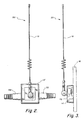
- a modified antenna 20 is shown in FIGS. 2 and 3.
- flat elongated plates 22 in the base 14′ extend approximately one quarter wave from the mast radiator 12 and serve as the dipole.
- Using the plates 22 permits slightly higher gain in the horizontal plane and thus better communication between the portable telephone 24 antenna on the interior of the vehicle and the dipole plates 22 which are mounted on the exterior of the vehicle.
- an additional parasitic element can be added to the base to create another alternative repeater 30 as is shown in FIG. 4.
- a base 14 ⁇ is modified to include two pairs of elements.
- a first dipole made up of one quarter wave segments 22 is positioned adjacent the glass 16 while a second pair of elements 26 are spaced at least 1/10 wavelength from the dipole pair and function as a reflector with a sensitive gain axis in the direction toward the front of the vehicle where the portable unit is most likely to be found.
- a similar result is achieved in repeater 40 by utilizing a parasitic element on the interior of the vehicle.
- the base 14′ containing the quarter wave segments 22 is affixed to the exterior of a glass plate 16 and an interior base 42 has a similar pair of parasitic elements 44 which function as a director. The combination is then more sensitive to radiation in the horizontal plane along a line generally parallel to the vehicular axis when the base 14′ is affixed to the rear window.
- the director element 44 should be less than one quarter wave length and should be spaced apart from the dipole segments 22 by at least 1/10 wavelength, which includes the thickness of the glass 16.
- FIG. 6 A preferred embodiment of the invention has been shown in FIG. 6.
- the alternative antenna 30 of FIG. 4 is combined with the interior base 42 of FIG. 5 to form a repeater combination 50 that includes dipole segments 22, reflector elements 26 and, on the interior base 42, direc- tor elements 44.
- This arrangement more nearly approximates a passive dipole array that is highly directional and which exhibits considerable gain along the sensitive axis which is orthogonal to the parasitic elements.
- the spacing between adjacent elements is at least 1/10 wavelength and the effective length of the director is less than 1/2 wavelength while the reflector is more than 1/2 wavelength.
- the director was set at .45 wave length while the radiator was set at .58 wave length
- FIG. 7 is an electrical diagram of the dipole 18 of FIG. 1 connected to the radiating mast 12. As shown, the connection to one arm of the dipole 18 is through a capacitive element 46 and through an inductive element 48 to the other arm of the dipole 18.
- the impedance values are selected for optimum electrical coupling between the radiator mast 12 and the dipole 18 at the frequencies of interest. Since the dipole elements of the other embodiments are electrically equivalent to the dipole of FIG. 1, the electrical interconnection would be similar.
- the repeater unit in its simplest embodiment includes a passive dipole which is coupled to a mast radiator that has unobstructed communication with a "cell".
- the portable telephone is operated within the vehicle which would otherwise effectively shield the telephone antenna from the "cell”.
- the telephone antenna and the dipole are now in direct, line of sight communication for transmission and reception of electrical signals.
- the signals received by the passive dipole are radiated from the radiator mast and the signals received by the radiator mast are radiated from the dipole to the interior telephone antenna at power levels which are sufficiently low to pose no human health hazard.
- additional parasitic elements are added, either to the externally mounted device or to an internally mounted device which is placed on the inner surface of the vehicle glass opposite the externally mounted device.
Abstract
Description
- The present invention relates to communications systems, and more particularly, to an improved combination for sending a radio transmission between a fixed antenna on the outside of a structure and a transceiver within the structure.
- Radio transmission and reception is difficult when a transceiver unit is located wholly within a structure that can act as a shield against radiation. For example, the interior of a motor vehicle may be isolated from radio signals that originate outside of the vehicle. Further, the transmission of radio signals from a transmitter which is located inside the vehicle may be blocked, as well.
- Transceivers which are located inside vehicles are commonly connected to an antenna which is mounted on the exterior of the vehicle by means of a coaxial cable or other wire link. Frequently, the radiating and receiving element of the antenna, which is located on the exterior of the vehicle, is capacitively coupled to the coaxial cable termination through a glass window of the vehicle, thereby eliminating the necessity of drilling holes in the body of the vehicle.
- The increasingly common use of cellular telephones operating in the 800 to 1000 MHz frequency range in motor vehicles has promoted the use of such through the glass antenna units since the cellular telephone preferably utilizes an antenna whose mast extends above the roof line of the vehicle for optimum reception and transmission. Through the glass antennas are easily mounted near the top of the rear window and the antenna mast can extend vertically above the roof line.
- Several types of cellular telephones are common today. A permanently installed car telephone has a direct power connection to the vehicle electrical supply and has a coaxial link to the installed antenna. A so called "transportable" cellular telephone is a similar telephone unit which includes a self contained power supply and a movable antenna so that it can be carried in a brief case. The permanent and transportable telephones are permitted to have a maximum transmitted power of 3.0 watts, which generally mandates the use of a coaxial transmission line to an antenna.
- In recent years, a smaller, compact and lightweight cellular telephone has been developed which can be hand held. This hand held or "portable" telephone, which usually has an integral antenna as a part of the unit, is permitted a radiated power level of only .6 watts. Such devices can be quite small and can fit in one's pocket. When used in an open space, the portable can easily communicate with a "cell" of the cellular system. However, difficulties can be encountered if one wishes to use a portable when inside a vehicle since the metal body of the vehicle acts as a shield to both incoming and outgoing signals.
- These difficulties can be overcome if the portable unit can be connected to an exterior antenna or if the portable can be operated through an open window in the vehicle and the metallic mass of the vehicle doesn't affect the receiving or radiation patterns of the antenna. One approach has been marketed under the trademark LARSEN® ANTENNAS by Larsen Electronics, Inc., of Vancouver, Washington, Model KGB-825. This unit is described as a "passive repeater antenna" which passes signals to and from the externally mounted gain antenna elements.
- Such an approach, however, fails to consider the low power available from the portable phone unit and the fact that the radiation pattern from the portable phone antenna is omnidirectional. This generally results in a very small fraction of the radiated power reaching the "repeater" and the external antenna unit. Similarly, the energy received by the external antenna is transferred to the "repeater" and omnidirectionally radiated within the vehicle. Only a small fraction of the received is signal is acquired by the portable phone antenna. Further, the external antenna and the internal dipole repeater are coupled capacitively, through the glass window, thereby resulting in some signal loss.
- According to the present invention, a directional passive repeater includes a dipole, which, in a preferred embodiment may be 1/2 wave, that is attached and matched to the external radiating/receiving antenna mast which is adhesively mounted to a window of a vehicle. Preferably, the rear window is utilized since it does not create any significant visual obstruction to the driver's field of view. It is, of course, possible to mount the antenna to the front windshield or to any of the fixed glass side windows.
- In the simplest embodiment of the present invention, the dipole is made of a sheet material to increase the surface area that faces the interior of the vehicle. This increases the gain in a direction orthogonal to the surface by about 2 dB over conventional round wires. It is then possible for a portable unit on the interior of the vehicle to "see" the externally mounted dipole and communicate with it both in the sending and receiving modes.
- In order to create more "gain" in the direction of the portable phone unit and its antenna, one or more parasitic elements may be added. For example, a "reflector" radial, that is approximately .58 wavelength, is spaced at least 1/10 wavelength (or multiples thereof) away from the dipole in a direction that is substantially orthogonal to the axis of the mast and the axis of the dipole and which creates gain for signals being exchanged between the dipole and the antenna of the portable unit. This reflector dipole can also be mounted on the exterior of the vehicle and is in communication with the portable unit by radiation through the glass.
- In another embodiment, a second parasitic radial, or "director" that is at least .45 wavelength, is mounted on the interior of the vehicle, on the opposing surface of the glass and at least 1/10 wavelength from the dipole. In yet other embodiments, additional parasitic elements acting as directors and/or reflectors can be added to increase the directionality of the array and to increase the gain, as well, with respect to signals between the repeater and the antenna of the portable unit. In adding additional elements, it is important that each element be spaced at least 1/10 wavelength from the next adjacent element.
- At the radio frequencies of operation, the glass has no shielding effect and a capacitative coupling through the glass is unnecessary. The resulting combination according to the present invention is a passive array which can be highly directional and can effectively impart "gain" to signals which are passed between the portable phone antenna and the external mast.
- In alternative embodiments, additional parasitic elements can be provided inside or outside of the vehicle to improve the gain and directionality of the array. Because there is no capacitative coupling through the glass, there are no "coupling" losses.
- The novel features which are characteristic of the invention, both as to structure and method of operation thereof, together with further objects and advantages thereof, will be understood from the following description, considered in connection with the accompanying drawings, in which the preferred embodiment of the invention is illustrated by way of example. It is to be expressly understood, however, that the drawings are for the purpose of illustration and description only, and they are not intended as a definition of the limits of the invention.
-
- FIG. 1 is a front view of a repeater according to the present invention;
- FIG. 2 is a front view of an alternative repeater;
- FIG. 3 is a side view of the repeater of FIG. 2;
- FIG. 4 is a diagram of a passive repeater array according to the present invention;
- FIG. 5 is a side view of an alternative embodiment including a parasitic element on each side of the vehicle glass;
- FIG. 6 is a side view of a preferred embodiment with two parasitic elements on one side of the glass and one on the other; and
- FIG. 7 is an electrical diagram of the repeater of the present invention.
- Turning first to FIG. 1, there is shown a
cellular repeater 10 according to a primitive embodiment of the present invention. As shown, therepeater 10 includes amast radiator 12 and abase 14 which is adhesively affixed to the exterior of aglass window element 16 of a vehicle. Theglass window element 16 is preferably the rear window of the vehicle, but can be any of the non conductive panels of the vehicle. While the rear window or back light is the mounting place of choice, the side windows or the front windshield of the vehicle can serve, as well. - Embedded in the
base 14 and extending substantially (but not necessarily) at right angles to the axis of themast radiator 12 are a pair ofquarter wave radials 18 that are connected to serve as a 1/2 wave dipole. Theradials 18 are coupled to themast radiator 12 and aid in the passive repeater function with respect to signals received by themast radiator 12 and with respect to signals that are received from a portable transmitter (not shown) in the near vicinity. - To improve the efficiency of the
radials 18, a modifiedantenna 20 is shown in FIGS. 2 and 3. Rather than using a small diameter round wire as the radial element, flatelongated plates 22 in thebase 14′ extend approximately one quarter wave from themast radiator 12 and serve as the dipole. Using theplates 22 permits slightly higher gain in the horizontal plane and thus better communication between theportable telephone 24 antenna on the interior of the vehicle and thedipole plates 22 which are mounted on the exterior of the vehicle. - To further improve the gain, an additional parasitic element can be added to the base to create another
alternative repeater 30 as is shown in FIG. 4. Abase 14˝ is modified to include two pairs of elements. A first dipole made up of onequarter wave segments 22 is positioned adjacent theglass 16 while a second pair ofelements 26 are spaced at least 1/10 wavelength from the dipole pair and function as a reflector with a sensitive gain axis in the direction toward the front of the vehicle where the portable unit is most likely to be found. - In the embodiment of FIG. 5, a similar result is achieved in repeater 40 by utilizing a parasitic element on the interior of the vehicle. As shown, the base 14′ containing the
quarter wave segments 22 is affixed to the exterior of aglass plate 16 and aninterior base 42 has a similar pair ofparasitic elements 44 which function as a director. The combination is then more sensitive to radiation in the horizontal plane along a line generally parallel to the vehicular axis when the base 14′ is affixed to the rear window. - Generally, the
director element 44 should be less than one quarter wave length and should be spaced apart from thedipole segments 22 by at least 1/10 wavelength, which includes the thickness of theglass 16. - A preferred embodiment of the invention has been shown in FIG. 6. Here, the
alternative antenna 30 of FIG. 4 is combined with theinterior base 42 of FIG. 5 to form arepeater combination 50 that includesdipole segments 22,reflector elements 26 and, on theinterior base 42, direc-tor elements 44. This arrangement more nearly approximates a passive dipole array that is highly directional and which exhibits considerable gain along the sensitive axis which is orthogonal to the parasitic elements. - As in the other embodiments, the spacing between adjacent elements is at least 1/10 wavelength and the effective length of the director is less than 1/2 wavelength while the reflector is more than 1/2 wavelength. In one experimental model, the director was set at .45 wave length while the radiator was set at .58 wave length
- FIG. 7 is an electrical diagram of the
dipole 18 of FIG. 1 connected to theradiating mast 12. As shown, the connection to one arm of thedipole 18 is through acapacitive element 46 and through aninductive element 48 to the other arm of thedipole 18. The impedance values are selected for optimum electrical coupling between theradiator mast 12 and thedipole 18 at the frequencies of interest. Since the dipole elements of the other embodiments are electrically equivalent to the dipole of FIG. 1, the electrical interconnection would be similar. - Thus there has been shown a passive antenna repeater for a portable cellular telephone which is to be used in the interior of a vehicle. The repeater unit in its simplest embodiment includes a passive dipole which is coupled to a mast radiator that has unobstructed communication with a "cell". The portable telephone is operated within the vehicle which would otherwise effectively shield the telephone antenna from the "cell".
- As a result, the telephone antenna and the dipole are now in direct, line of sight communication for transmission and reception of electrical signals. The signals received by the passive dipole are radiated from the radiator mast and the signals received by the radiator mast are radiated from the dipole to the interior telephone antenna at power levels which are sufficiently low to pose no human health hazard.
- In alternative embodiments, additional parasitic elements are added, either to the externally mounted device or to an internally mounted device which is placed on the inner surface of the vehicle glass opposite the externally mounted device.
- Other modifications and alterations will appear to those skilled in the art and, accordingly, the scope of the invention should be limited only by the scope of the claims appended hereto.
Claims (8)
- A repeater assembly for use with a transceiver located within a shielding environment having areas that are transparent to electromagnetic radiation, comprising in combination:a) an antenna, including a radiator having an axis, said antenna being mounted to the exterior of the shielding environment in a radiation transparent area thereof;b) a dipole element attached to said antenna and extending in a direction to maximize transmission and reception in a plane that intersects said antenna axis; andc) tuning means electrically coupling said dipole element to said antenna radiator,whereby a transceiver within the shielding environment is in radiant energy communication with said dipole element and, by means of said radiator, communicates with remote transmitters and receivers that are in radiant energy communication with said radiator.
- A repeater assembly as in claim 1, further including a parasitic element mounted on the interior of the shielding environment in the transparent area thereof adjacent said antenna, said parasitic element being spaced at least 1/10 wavelength from said dipole and arranged to be substantially parallel thereto for enhancing transmission and reception in a selected direction, whereby gain is imparted to signals transmitted in the selected direction between the repeater assembly and a transceiver within the shielded environment.
- A repeater assembly as in claim 1, further including a parasitic element in said antenna substantially parallel to said dipole for enhancing transmission and reception in a selected direction whereby gain is imparted to signals transmitted in the selected direction between the repeater assembly and a transceiver within the shielded environment.
- A repeater assembly as in claim 3, further including a parasitic element mounted on the interior of the shielding environment in the transparent area thereof adjacent said antenna, said parasitic element being spaced at least 1/10 wavelength from said dipole and arranged to be substantially parallel thereto for enhancing transmission and reception in a selected direction, whereby gain is imparted to signals transmitted in the selected direction between the repeater assembly and a transceiver within the shielded environment.
- A repeater assembly for use with a transceiver located within a shielding environment having areas that are transparent to electromagnetic radiation, comprising in combination:a) an antenna, including a mast element having an axis, said antenna being adapted to radiate and receive cellular telephone signals;b) a first base member coupled to said antenna and adapted to be mounted to the exterior of the shielding environment in a radiation transparent area thereof; andc) a dipole member mounted on said first base member amd electrically coupled to said antenna through reactive impedance elements, said dipole member extending in a direction that is not parallel to said mast axis for maximizing transmission and reception in a plane that intersects said mast axis;whereby a transceiver within the shielding environment is in radiant energy communication with said dipole member and, by means of said mast, communicates with remote transmitters and receivers that are in radiant energy communication with said mast.
- A repeater assembly as in claim 5, further including a parasitic element mounted in a second base member that is adapted to be installed on the interior of the shielding environment in the transparent area thereof, adjacent said first base member, said parasitic element being spaced at least 1/10 wavelength from said dipole member and arranged to be substantially parallel thereto for enhancing transmission and reception in a selected direction, whereby gain is imparted to signals transmitted in the selected direction between the repeater assembly and a transceiver within the shielded environment.
- A repeater assembly as in claim 6, further including a parasitic element in said first base member substantially parallel to said dipole member for enhancing transmission and reception in a selected direction whereby gain is imparted to signals transmitted in the selected direction between the repeater assembly and a transceiver within the shielded environment.
- A repeater assembly as in claim 7, further including a parasitic element counted in a second base member adapted to be mounted on the interior of the shielding environment in the transparent area thereof adjacent said first base member, said parasitic element being spaced at least 1/10 wavelength from said dipole member and arranged to be substantially parallel thereto for enhancing transmission and reception in a selected direction, whereby gain is imparted to signals transmitted in the selected direction between the repeater assembly and a transceiver within the shielded environment.
Applications Claiming Priority (2)
| Application Number | Priority Date | Filing Date | Title |
|---|---|---|---|
| US52718190A | 1990-05-22 | 1990-05-22 | |
| US527181 | 1990-05-22 |
Publications (3)
| Publication Number | Publication Date |
|---|---|
| EP0458592A2 true EP0458592A2 (en) | 1991-11-27 |
| EP0458592A3 EP0458592A3 (en) | 1992-01-15 |
| EP0458592B1 EP0458592B1 (en) | 1996-01-31 |
Family
ID=24100439
Family Applications (1)
| Application Number | Title | Priority Date | Filing Date |
|---|---|---|---|
| EP91304582A Expired - Lifetime EP0458592B1 (en) | 1990-05-22 | 1991-05-21 | Passive cellular telephone antenna system |
Country Status (7)
| Country | Link |
|---|---|
| EP (1) | EP0458592B1 (en) |
| JP (1) | JPH0426233A (en) |
| KR (1) | KR910020966A (en) |
| AT (1) | ATE133814T1 (en) |
| DE (1) | DE69116733T2 (en) |
| IE (1) | IE72170B1 (en) |
| NO (1) | NO911961L (en) |
Cited By (6)
| Publication number | Priority date | Publication date | Assignee | Title |
|---|---|---|---|---|
| GB2266997A (en) * | 1992-05-07 | 1993-11-17 | Wallen Manufacturing Limited | Radio antenna. |
| EP0684704A2 (en) * | 1994-05-06 | 1995-11-29 | AT&T Corp. | A diversity antenna for a wrist telephone |
| US5600333A (en) * | 1995-01-26 | 1997-02-04 | Larsen Electronics, Inc. | Active repeater antenna assembly |
| US5898408A (en) * | 1995-10-25 | 1999-04-27 | Larsen Electronics, Inc. | Window mounted mobile antenna system using annular ring aperture coupling |
| US6172651B1 (en) | 1995-10-25 | 2001-01-09 | Larsen Electronics, Inc. | Dual-band window mounted antenna system for mobile communications |
| DE10243695B4 (en) * | 2002-09-20 | 2005-12-22 | Ikoda Gmbh | Passive repeater system for radio communication for buildings and other buildings with high attenuation or shielding of electromagnetic waves for radio communication |
Citations (4)
| Publication number | Priority date | Publication date | Assignee | Title |
|---|---|---|---|---|
| FR2081211A7 (en) * | 1970-03-18 | 1971-12-03 | Saint Gobain | |
| US4794319A (en) * | 1986-07-03 | 1988-12-27 | Alliance Research Corporation | Glass mounted antenna |
| EP0429203A1 (en) * | 1989-11-15 | 1991-05-29 | Nokia Mobile Phones Ltd. | Antenna system for a vehicle |
| EP0431640A2 (en) * | 1989-12-08 | 1991-06-12 | Larsen Electronics, Inc. | Mobile cellular antenna system |
-
1990
- 1990-10-17 KR KR1019900016551A patent/KR910020966A/en not_active Application Discontinuation
- 1990-10-26 JP JP2287408A patent/JPH0426233A/en active Pending
-
1991
- 1991-05-21 EP EP91304582A patent/EP0458592B1/en not_active Expired - Lifetime
- 1991-05-21 AT AT91304582T patent/ATE133814T1/en not_active IP Right Cessation
- 1991-05-21 DE DE69116733T patent/DE69116733T2/en not_active Expired - Fee Related
- 1991-05-22 NO NO91911961A patent/NO911961L/en unknown
- 1991-05-22 IE IE175691A patent/IE72170B1/en unknown
Patent Citations (4)
| Publication number | Priority date | Publication date | Assignee | Title |
|---|---|---|---|---|
| FR2081211A7 (en) * | 1970-03-18 | 1971-12-03 | Saint Gobain | |
| US4794319A (en) * | 1986-07-03 | 1988-12-27 | Alliance Research Corporation | Glass mounted antenna |
| EP0429203A1 (en) * | 1989-11-15 | 1991-05-29 | Nokia Mobile Phones Ltd. | Antenna system for a vehicle |
| EP0431640A2 (en) * | 1989-12-08 | 1991-06-12 | Larsen Electronics, Inc. | Mobile cellular antenna system |
Cited By (7)
| Publication number | Priority date | Publication date | Assignee | Title |
|---|---|---|---|---|
| GB2266997A (en) * | 1992-05-07 | 1993-11-17 | Wallen Manufacturing Limited | Radio antenna. |
| EP0684704A2 (en) * | 1994-05-06 | 1995-11-29 | AT&T Corp. | A diversity antenna for a wrist telephone |
| EP0684704A3 (en) * | 1994-05-06 | 1999-11-10 | AT&T Corp. | A diversity antenna for a wrist telephone |
| US5600333A (en) * | 1995-01-26 | 1997-02-04 | Larsen Electronics, Inc. | Active repeater antenna assembly |
| US5898408A (en) * | 1995-10-25 | 1999-04-27 | Larsen Electronics, Inc. | Window mounted mobile antenna system using annular ring aperture coupling |
| US6172651B1 (en) | 1995-10-25 | 2001-01-09 | Larsen Electronics, Inc. | Dual-band window mounted antenna system for mobile communications |
| DE10243695B4 (en) * | 2002-09-20 | 2005-12-22 | Ikoda Gmbh | Passive repeater system for radio communication for buildings and other buildings with high attenuation or shielding of electromagnetic waves for radio communication |
Also Published As
| Publication number | Publication date |
|---|---|
| KR910020966A (en) | 1991-12-20 |
| DE69116733D1 (en) | 1996-03-14 |
| JPH0426233A (en) | 1992-01-29 |
| EP0458592B1 (en) | 1996-01-31 |
| DE69116733T2 (en) | 1996-06-05 |
| IE911756A1 (en) | 1991-12-04 |
| EP0458592A3 (en) | 1992-01-15 |
| IE72170B1 (en) | 1997-03-26 |
| NO911961L (en) | 1991-11-25 |
| NO911961D0 (en) | 1991-05-22 |
| ATE133814T1 (en) | 1996-02-15 |
Similar Documents
| Publication | Publication Date | Title |
|---|---|---|
| US5181043A (en) | Passive repeater for cellular phones | |
| US5600333A (en) | Active repeater antenna assembly | |
| US4794319A (en) | Glass mounted antenna | |
| US6999032B2 (en) | Antenna system employing floating ground plane | |
| US6031492A (en) | Mobile cradle antenna and heat sink enhancement | |
| CA1287916C (en) | Near-isotropic low-profile microstrip radiator especially suited for use as a mobile vehicle antenna | |
| KR100300934B1 (en) | Antenna glass window inserted into the window opening of a metal automobile body | |
| EP1365475B1 (en) | Multi-band antenna using an electrically short cavity reflector | |
| US5283589A (en) | Window mountable UHF mobile antenna system | |
| US20020140611A1 (en) | Antenna arrangement | |
| KR20010075231A (en) | Capacitively-tune broadband antenna structure | |
| US5343214A (en) | Cellular mobile communications antenna | |
| JPS61269403A (en) | Antenna | |
| CN109755727B (en) | Antenna assembly and mobile terminal | |
| GB2293050A (en) | An antenna used for the transmission or the reception of a radio frequency signal, a transmitter and a remote control receiver. | |
| EP0854533B1 (en) | Antenna system for a motor vehicle | |
| EP0458592B1 (en) | Passive cellular telephone antenna system | |
| JP3743263B2 (en) | Antenna device for automobile telephone | |
| US5298907A (en) | Balanced polarization diversified cellular antenna | |
| US6396443B1 (en) | Integrated flat antenna and radio frequency unit for point-to-point microwave radios | |
| US4694301A (en) | Antenna particularly suited for use with a mobile communications system | |
| JPS6356731B2 (en) | ||
| US20030162524A1 (en) | Motor vehicle outside rear-view mirror | |
| JP2002368514A (en) | Glass antenna system for vehicle | |
| JPH1168449A (en) | Incorporated antenna for radio equipment |
Legal Events
| Date | Code | Title | Description |
|---|---|---|---|
| PUAI | Public reference made under article 153(3) epc to a published international application that has entered the european phase |
Free format text: ORIGINAL CODE: 0009012 |
|
| AK | Designated contracting states |
Kind code of ref document: A2 Designated state(s): AT BE CH DE DK ES FR GB GR IT LI LU NL SE |
|
| PUAL | Search report despatched |
Free format text: ORIGINAL CODE: 0009013 |
|
| AK | Designated contracting states |
Kind code of ref document: A3 Designated state(s): AT BE CH DE DK ES FR GB GR IT LI LU NL SE |
|
| 17P | Request for examination filed |
Effective date: 19920622 |
|
| 17Q | First examination report despatched |
Effective date: 19940421 |
|
| GRAA | (expected) grant |
Free format text: ORIGINAL CODE: 0009210 |
|
| AK | Designated contracting states |
Kind code of ref document: B1 Designated state(s): AT BE CH DE DK ES FR GB GR IT LI LU NL SE |
|
| PG25 | Lapsed in a contracting state [announced via postgrant information from national office to epo] |
Ref country code: IT Free format text: LAPSE BECAUSE OF FAILURE TO SUBMIT A TRANSLATION OF THE DESCRIPTION OR TO PAY THE FEE WITHIN THE PRE;WARNING: LAPSES OF ITALIAN PATENTS WITH EFFECTIVE DATE BEFORE 2007 MAY HAVE OCCURRED AT ANY TIME BEFORE 2007. THE CORRECT EFFECTIVE DATE MAY BE DIFFERENT FROM THE ONE RECORDED.SCRIBED TIME-LIMIT Effective date: 19960131 Ref country code: GR Free format text: LAPSE BECAUSE OF FAILURE TO SUBMIT A TRANSLATION OF THE DESCRIPTION OR TO PAY THE FEE WITHIN THE PRESCRIBED TIME-LIMIT Effective date: 19960131 Ref country code: DK Effective date: 19960131 Ref country code: CH Effective date: 19960131 Ref country code: NL Free format text: LAPSE BECAUSE OF FAILURE TO SUBMIT A TRANSLATION OF THE DESCRIPTION OR TO PAY THE FEE WITHIN THE PRESCRIBED TIME-LIMIT Effective date: 19960131 Ref country code: BE Effective date: 19960131 Ref country code: AT Effective date: 19960131 Ref country code: ES Free format text: THE PATENT HAS BEEN ANNULLED BY A DECISION OF A NATIONAL AUTHORITY Effective date: 19960131 Ref country code: LI Effective date: 19960131 |
|
| REF | Corresponds to: |
Ref document number: 133814 Country of ref document: AT Date of ref document: 19960215 Kind code of ref document: T |
|
| REF | Corresponds to: |
Ref document number: 69116733 Country of ref document: DE Date of ref document: 19960314 |
|
| ET | Fr: translation filed | ||
| PG25 | Lapsed in a contracting state [announced via postgrant information from national office to epo] |
Ref country code: SE Effective date: 19960430 |
|
| PG25 | Lapsed in a contracting state [announced via postgrant information from national office to epo] |
Ref country code: LU Free format text: LAPSE BECAUSE OF NON-PAYMENT OF DUE FEES Effective date: 19960531 |
|
| NLV1 | Nl: lapsed or annulled due to failure to fulfill the requirements of art. 29p and 29m of the patents act | ||
| REG | Reference to a national code |
Ref country code: CH Ref legal event code: PL |
|
| PLBE | No opposition filed within time limit |
Free format text: ORIGINAL CODE: 0009261 |
|
| STAA | Information on the status of an ep patent application or granted ep patent |
Free format text: STATUS: NO OPPOSITION FILED WITHIN TIME LIMIT |
|
| 26N | No opposition filed | ||
| PGFP | Annual fee paid to national office [announced via postgrant information from national office to epo] |
Ref country code: FR Payment date: 19980511 Year of fee payment: 8 |
|
| PGFP | Annual fee paid to national office [announced via postgrant information from national office to epo] |
Ref country code: GB Payment date: 19980512 Year of fee payment: 8 |
|
| PGFP | Annual fee paid to national office [announced via postgrant information from national office to epo] |
Ref country code: DE Payment date: 19980529 Year of fee payment: 8 |
|
| PG25 | Lapsed in a contracting state [announced via postgrant information from national office to epo] |
Ref country code: GB Free format text: LAPSE BECAUSE OF NON-PAYMENT OF DUE FEES Effective date: 19990521 |
|
| GBPC | Gb: european patent ceased through non-payment of renewal fee |
Effective date: 19990521 |
|
| PG25 | Lapsed in a contracting state [announced via postgrant information from national office to epo] |
Ref country code: FR Free format text: LAPSE BECAUSE OF NON-PAYMENT OF DUE FEES Effective date: 20000131 |
|
| PG25 | Lapsed in a contracting state [announced via postgrant information from national office to epo] |
Ref country code: DE Free format text: LAPSE BECAUSE OF NON-PAYMENT OF DUE FEES Effective date: 20000301 |
|
| REG | Reference to a national code |
Ref country code: FR Ref legal event code: ST |