EP0458879B1 - Intravenous system for delivering a beneficial agent - Google Patents
Intravenous system for delivering a beneficial agent Download PDFInfo
- Publication number
- EP0458879B1 EP0458879B1 EP90903659A EP90903659A EP0458879B1 EP 0458879 B1 EP0458879 B1 EP 0458879B1 EP 90903659 A EP90903659 A EP 90903659A EP 90903659 A EP90903659 A EP 90903659A EP 0458879 B1 EP0458879 B1 EP 0458879B1
- Authority
- EP
- European Patent Office
- Prior art keywords
- agent
- fluid
- wall portion
- formulator
- container
- Prior art date
- Legal status (The legal status is an assumption and is not a legal conclusion. Google has not performed a legal analysis and makes no representation as to the accuracy of the status listed.)
- Expired - Lifetime
Links
Images

Classifications
-
- A—HUMAN NECESSITIES
- A61—MEDICAL OR VETERINARY SCIENCE; HYGIENE
- A61M—DEVICES FOR INTRODUCING MEDIA INTO, OR ONTO, THE BODY; DEVICES FOR TRANSDUCING BODY MEDIA OR FOR TAKING MEDIA FROM THE BODY; DEVICES FOR PRODUCING OR ENDING SLEEP OR STUPOR
- A61M5/00—Devices for bringing media into the body in a subcutaneous, intra-vascular or intramuscular way; Accessories therefor, e.g. filling or cleaning devices, arm-rests
- A61M5/14—Infusion devices, e.g. infusing by gravity; Blood infusion; Accessories therefor
- A61M5/1407—Infusion of two or more substances
Definitions
- This invention pertains to a parenteral drug delivery system, and to a drug formulation chamber in combination with a drug delivery device.
- the invention relates also to a method of parenterally (e.g., intravenously) administering a drug, and to a method of formulating the drug during parenteral administration.
- the parenteral administration of medical liquids is an established clinital practice.
- the liquids are administered particularly intravenously, and the practice is used extensively as an integral part of the daily treatment of medical and surgical patients.
- the liquids commonly administered include blood and blood substitutes, dextrose solutions, electrolyte solutions and saline.
- the liquids are administered from an intravenous (IV) delivery system having a container suspended above the patient, with the liquid flowing through a catheter hypodermic needle set to the patient.
- IV intravenous
- beneficial agents have been administered intravenously by one of the following methods: (1) temporarily removing or disconnecting the IV system administering the agent to the patient, then administering the drug by hypodermic injection (either into the distonnected IV line or directly into the vein of the patient), followed by reinserting the IV system into the patient; (2) adding the agent to the IV liquid in the container which is then carried by the flow of the liquid to the patient; (3) adding the agent to an IV liquid in a secondary container (called a partial fill) that is then connected to the primary IV line; (4) adding the agent to an IV liquid contained in a piggyback vial which is subsequently connected to the primary IV line; or (5) administering intravenously an IV liquid containing a beneficial agent using a pump.
- U.S. Pat. 4,511,353 (and in related U.S. Patents 4,740,103; 4,740,200 and 4,740,201) developed a formulation chamber adapted to easily fit into a conventional IV administration set.
- the formulation chamber is adapted to contain a drug delivery device for delivering a drug or other beneficial agent into the IV fluid flowing through the formulation chamber.
- the drug delivery device within the formulation chamber is selected from osmotic pumps ( Figures 2a, 2b, 9, 10 and 11), release rate controlling membranes surrounding a drug reservoir ( Figures 3-5), rate-controlled delivery reservoirs within a pocket in the drug formulation chamber, the pocket formed by a permeable membrane or screen/mesh which allows passage of both IV fluid and drug solution therethrough ( Figures 12 and 13) and polymer matrices containing the drug, the drug being able to diffuse through the matrix into the flowing IV fluid ( Figures 6-8).
- Wolfe et al in U.S. Patent 4,533,348 disclose a drug dispenser adapted to be placed in a conventional IV administration set.
- a beneficial agent is housed in a formulation chamber in the dispenser and a membrane permeable to fluid and agent defines one boundary of the formulation chamber.
- a piston is slidably disposed in the dispenser for governing the flow of fluid through the dispenser, or for permitting fluid to contact the membrane and enter the formulation chamber for forming a solution containing agent that flows through the outlet.
- Some of these devices provide the advantage of controlling the rate at which the drug or other beneficial agent is released into the IV fluid, independently of the rate at which the IV fluid flows through the formulation chamber.
- the drug delivery systems disclosed in these patents do not allow a medical technician to quickly and easily change the type of beneficial agent being delivered into the flowing IV fluid or to quickly and easily change the delivery rate of the beneficial agent so delivered.
- the drug formulation chamber is disassembled, there is a break in the sterile field which can lead to patient infection and therefore necessitates re-sterilizing the entire apparatus.
- a drug formulation chamber which can deliver one or more beneficial agents, such as a drug, into an IV fluid flowing in a standard IV administration set and which can quickly and easily change the type and/or change the delivery rate of beneficial agent so delivered without contaminating the sterile field.
- a parenteral (e.g., intravenous) delivery system which delivers an agent at a controlled rate into a flowing parenteral fluid for optimizing the care of an animal (e.g., a human) whose prognosis benefits from parenteral delivery.
- Another object of the invention is to provide an intravenous delivery system having an agent formulation chamber which is adapted to be used with a transdermal-type drug delivery device which can deliver one or more beneficial agents, such as a drug, into an IV fluid flowing through the formulation chamber and which can quickly and easily change the type and/or change the delivery rate of beneficial agent so delivered without contaminating the sterile conditions within the drug formulation chamber.
- beneficial agents such as a drug
- a further object of the invention is to provide an intravenous therapeutic system including a container of an intravenous medical fluid and a drug formulation chamber in combination with a drug delivery device which can deliver drug, to a flowing IV fluid, at a rate which is variable and which is accurately controlled by the components of the system.
- the agent formulator comprises a chamber having fluid inlet and fluid outlet means to maintain a continuous flow of a parenterally acceptable fluid therethrough.
- the chamber has a wall portion that is permeable to a beneficial agent to be delivered into the fluid.
- the beneficial agent should be soluble in the parenteral fluid to enable the agent to diffuse through the wall portion.
- a flow distributor is provided within the chamber for distributing the flow of parenteral fluid along an interior surface of the wall portion.
- An agent delivery device is releasably attached to an easily accessible exterior surface of the wall portion.
- the delivery device includes a reservoir containing the beneficial agent to be delivered into the parenteral fluid.
- the delivery device is a transdermal type drug delivery device comprising a laminate including a backing member, a middle reservoir containing the beneficial agent and an adhesive surface adapted to releasably adhere to the exterior surface of the wall portion.
- the agent delivery device also includes a rate controlling membrane which controls the rate at which the agent is delivered through the wall portion.
- the fluid flowing through the chamber is distributed by the flow distributor along the interior surface of the wall portion, thereby causing the agent to diffuse from the device through the wall portion and into the flowing fluid.
- the agent is delivered at a rate that is controlled substantially by the formulator and which is substantially independent of the volumetric flow rate of the fluid flowing through the chamber.
- the present invention also provides a parenteral delivery system for administering an agent parenterally to an animal.
- the system comprises in combination, a container of a pharmaceutically acceptable parenteral fluid that is a carrier for the agent and a parenteral fluid administration set.
- the administration set is connected to the container for permitting the fluid to flow from the container through the administration set to the animal.
- the administration set comprises a drip chamber, tubing extending from the drip chamber to the animal, and an agent formulator connected into the tubing such that the intravenous fluid flows through the formulator.
- the formulator includes a chamber having fluid inlet and outlet means to maintain a continuous flow of the parenteral fluid therethrough.
- the chamber has a wall portion that is permeable to a beneficial agent to be delivered into the fluid.
- the beneficial agent should be soluble in the parenteral fluid to enable the agent to diffuse through the wall portion.
- a flow distributor is provided within the chamber for distributing the flow of parenteral fluid along an interior surface of the wall portion.
- the formulator also includes an agent delivery device releasably attached to an easily accessible external surface of the wall portion.
- the delivery device includes a reservoir containing the beneficial agent to be delivered.
- the delivery device is a transdermal drug delivery device comprising a laminate including a backing member, a middle reservoir containing the beneficial agent and an adhesive surface adapted to releasably adhere to the external surface of the wall portion.
- the agent delivery device includes a rate controlling membrane which controls the rate at which the agent is delivered through the wall portion.
- the fluid flowing through the chamber is distributed by the flow distributor along the internal surface of the wall portion, causing the agent to diffuse from the device through the wall portion and into the flowing fluid.
- the agent is delivered at a rate which is controlled substantially by the formulator and which is substantially independent of the volumetric flow rate of the fluid flowing through the chamber.
- the present invention further provides a method for the controlled parenteral administration of a beneficial agent, such as a drug, to an animal, such as a human.
- the method comprises the steps of allowing a pharmaceutically acceptable parenteral fluid, which is a carrier for the agent, to flow through an agent formulation chamber.
- the chamber has an inlet communicating with a container of the parenteral fluid and an outlet communicating with the animal.
- the chamber also has a wall portion that is permeable to the agent and prevents convective flow of parenteral fluid therethrough.
- the method further comprises the steps of distributing the flow of parenteral fluid along an interior surface of the wall portion and releasably attaching an agent delivery device to an accessible exterior surface of the wall portion.
- the delivery device includes a reservoir containing the beneficial agent to be delivered.
- the delivery device is a transdermal drug delivery device comprising a laminate including a backing member, a middle reservoir containing the beneficial agent and an adhesive surface adapted to releasably adhere to the external surface of the wall portion.
- the agent delivery device includes a rate controlling membrane which controls the rate at which the agent is delivered through the wall portion.
- the fluid flowing through the chamber is distributed along the interior surface of the wall portion, causing the agent to diffuse from the device through the wall portion and into the flowing fluid.
- the agent is released at a rate which is controlled substantially by the delivery device and which is substantially independent of the volumetric flow rate of the fluid flowing through the chamber.
- the method is effective to administer the drug/agent to the animal in a beneficially effective amount over a prolonged period of time.
- Figure 1 illustrates an operative intravenous delivery system, generally designated by the numeral 10, showing the positioning of an agent formulator 30 therein.
- System 10 comprises a container 12 that contains a fluid 13 suitable for intravenous administration, and an administration set, generally designated 14.
- the fluid 13 in container 12 will typically be a medical fluid, i.e., a sterile solution such as an aqueous solution of dextrose, saline, and/or electrolytes.
- Fluid 13 is a vehicle for intravenous administration of a pharmaceutical agent to a recipient.
- Container 12 is manufactured from glass or plastic, and is preferably of the no air-tube vacuum type and thus it is used with an administration set that has an air inlet filter.
- Container 12 can be rigid, semi-rigid or flexible in structure, and it is usually adapted to be hung neck-down from a hanger 15 by a handle 16 that connects or surrounds container 12.
- the neck of container 12 is covered by a closure 17, generally made of rubber and air-tight.
- container 12 can take the form of an infusor or a syringe pump (not shown in the Figures), and in particular a portable infusor or syringe pump, of the kind known in this art.
- Administration set 14 and container 12 are interconnected by piercing closure 17 with one end of a hollow spike 18 attached to or formed as a part of administration set 14.
- Spike 18 is equipped with a side air vent 19.
- the other end of spike 18 is enlarged and fits snugly into a drip chamber 22.
- Drip chamber 22 traps air contained in the set 14 and facilitates adjusting the flow rate of intravenous fluid 13 from container 12 as the flow proceeds drop wise.
- the outlet at the bottom of drip chamber 22 is connected to a first segment of tubing 23 which fits into agent formulator 30, the details of which are presented in Figures 2 and 3.
- a second segment of tubing 25 leads from agent formulator 30 to bacterial filter 27.
- a third segment of tubing 29 extends from filter 27 to an infusion agent receptor site, terminating in an adapter-needle assembly 28 that is inserted into a vein of a warm-blooded animal 20, shown as a human arm.
- a piece of tape 21 holds adapter-needle assembly 28 firmly in place on the recipient's arm.
- the administration set can also include a pair of tubing clamps 24 and 26 located on either side of formulator 30 which may be used to govern or stop the flow of intravenous fluid through the intravenous delivery system 10.
- a portion of the wall of container 12 is comprised of a material 11 which is permeable to the beneficial agent contained within, and delivered by, the delivery device 40.
- the wall portion 11 forms a "drug delivery window" within the otherwise impermeable wall of container 12.
- the IV fluid 13 must be in contact with the interior surface of wall portion 11. Accordingly, the wall portion 11 is preferably located in a downstream portion of the wall of container 12 most preferably adjacent the neck of container 12.
- agent formulator 30 may be provided downstream from the container 12.
- Agent formulator 30, as seen in Figures 2 and 3, comprises a wall 32 forming a chamber 34. At least a portion of the wall 32 is comprised of a material 36 which is permeable to the beneficial agent contained within, and delivered by, the delivery device 40.
- the wall portion 36 forms a drug delivery window, similar to wall portion 11, within the otherwise impermeable wall 32 which may be formed of glass, plastic or the like.
- a flow diverter 38 is provided within-chamber 34.
- the flow diverter 38 is secured within chamber 34 by supports 39.
- formulator 30 has a cylindrical shape and the wall portion 36 extends around the entire circumference of formulator 30.
- the flow diverter 38 also preferably has a roughly cylindrical shape.
- the entire chamber 34 preferably remains filled with the flowing IV fluid 13 to ensure that the entire interior surface of wall portion 36 is in contact with the flowing IV fluid 13.
- the flow diverter 38 provides two important functions in the formulator 30 of the present invention. First, the flow diverter 38 diverts the flow of IV fluid in the direction shown by the arrows in Figure 2, i.e., along the interior surface of wall portion 36.
- the flow diverter 38 minimizes the dead volume within formulator 30. Those skilled in the art will appreciate that the flow diverter 38 forces the IV fluid to flow in a relatively constricted space between the flow diverter 38 and the wall portion 36, thereby enabling a greater percentage of the IV fluid 13 to contact the interior surface of wall portion 36.
- Flow diverter 38 creates a higher liquid flow velocity (for any given liquid volumetric flow rate) along the interior surface of wall portion 36 which helps eliminate any stagnant fluid layer.
- the thickness of the stagnant fluid layer along the walls of chamber 34 decreases as the fluid flow velocity through chamber 34 increases. This creates several beneficial effects.
- the higher fluid flow velocity also promotes higher drug transfer rates by maintaining a lower drug concentration in the IV fluid adjacent the wall portion 36.
- Agent formulator 60 is also connectable to an intravenous administration set by connecting to inlet tubing 23 and outlet tubing 25.
- Agent formulator 60 comprises a wall 32 and a wall portion 36.
- the delivery device 40 is adapted to be secured to wall portion 36.
- Wall portion 36 is comprised of a material which is permeable to the beneficial agent contained within, and delivered by, the delivery device 40.
- the wall portion 36 forms a drug delivery window, similar to wall portion 11 ( Figure 1) and wall portion 36 ( Figure 2), within the otherwise impermeable wall 32 which is preferably formed of a moldable plastic, e.g., polyethylene terephthalate.
- wall 32 is molded to form a tortuous flow path 67 defined by a plurality of flow diverters 68.
- Wall portion 36 may be bonded to the wall 32 using heat and pressure according to well known methods.
- the IV fluid 13 flows along the interior surface of wall portion 36 as shown by the arrows.
- the tortuous flow path 67 achieves the same benefits of higher liquid flow velocity, elimination of stagnant fluid layers, reduction in air or gas bubbles and higher drug transfer rates mentioned above with respect to flow diverter 38 ( Figures 2 and 3).
- the wall portions 11 and 36 may be comprised of known drug permeable and/or microporous materials which allow the beneficial agent delivered by device 40 to diffuse therethrough but which prevent convective IV fluid flow therethrough.
- the composition of wall portions 11 and 36 should be selected in accordance with the type of beneficial agent being delivered by device 40.
- the wall portions 11 and 36 should be comprised of a polymeric composition that allows a drug or other beneficial agent delivered by device 40 to diffuse through the wall portion and into the interior of container 12 and/or into chamber 34.
- Representative polymers for forming wall portions 11 and 36 include olefin polymers, vinyl polymers, condensation polymers, addition polymers, rubber polymers and silicone polymers, and in particular, polyethylene, polypropylene, polyvinyl acetate, polyvinyl acetal, polyvinyl chloride, polyamides, polyesters, butadiene rubber, organo-silicone polymers and copolymers thereof.
- the wall portions 11 and 36 are preferably comprised of a hydrophilic or microporous material.
- suitable hydrophilic materials include polyurethanes, polyvinyl alcohols, polyamides and cellophane Of these, polyurethanes and cellophane are most preferred.
- Suitable microporous materials are described below in connection with the delivery of polypeptides, proteins and other macromolecules.
- the wall portions 11 and 36 are preferably comprised of a lipophilic material.
- suitable lipophilic materials include natural rubbers, silicone rubbers, Hytrel® (a thermoplastic polyester elastomer sold by E.I. DuPont de Nemours of Wilmington, DE), ethylene vinyl acetate (EVA), polyvinyl chloride, and Kraton® (a styrene-butadiene block copolymer sold by Shell Chemical Co. of Houston, TX). Of these, ethylene vinyl acetate copolymers, silicone rubbers and natural rubbers are preferred.
- the wall portions 11 and 36 are preferably comprised of a microporous material.
- the pores in the microporous material will generally have a size of less than about 0.2 microns, and preferably about 0.01 to 0.2 microns. Pores having the above recited size ranges are too small to allow bacterial cells to pass through the pores and can thereby maintain the sterility of the container 12 and/or the chamber 34.
- microporous materials having pore sizes in the above mentioned range will allow water molecules from the parenteral fluid to diffuse into the membrane. In some cases, the exterior of the wall portions 11 and 36 will feel wet to the touch.
- microporous membranes having the above mentioned pore size ranges will be effective to prevent convective flow losses of water-based parenteral fluids through the wall portions 11 and 36.
- the microporous wall portions 11 and 36 can be treated with a water non-wetting material to further reduce capillary IV fluid losses through the wall portions 11 and 36.
- the delivery device 40 may utilize a carrier which is immiscible in water.
- the beneficial agent is suspended in a water-immiscible fluid carrier (e.g., an oil).
- a water-immiscible fluid carrier e.g., an oil
- microporous materials include Celgard® (a microporous polypropylene film sold by Celanese Chemical Co. of Dallas, TX) cellophane, glass frits, vycor glass, porous glass and microporous membranes of the type utilized in known elementary osmotic pumps. Of these, porous glass is most preferred.
- Selection of polymers for forming wall portions 11 and 36 for the passage of a drug therethrough can be determined by measuring the rate of diffusion through the polymeric wall material.
- Various techniques can be used to determine the permeability of a homopolymer, copolymer, or terpolymer to the passage of a drug.
- One method that can be used is to position a film of the polymer, of known thickness, as a barrier between a rapidly stirred, saturated solution of the drug and a rapidly stirred solvent bath (typically water), at a constant temperature, typically 25°C, and periodically measuring the concentration in the drug solution and in the solvent bath.
- the permeability coefficient, P, of the polymeric film may be determined from Fick's Law of Diffusion.
- Wall portions 11 and 36 may also optionally contain a plasticizer such as a member selected from the group consisting of phthalate ester, adipate ester, sebacate ester, azelate ester, di(2-ethylhexyl) phthalate, butyl phthalyl butyl glycolate, diamyl phthalate, dibutyl succinate, diethylene glycol dipropionate, glycerol monooleate, ethyl phthalyl ethyl glycolate, triethyl citrate, tributyl citrate, trialkyl citrates sold under the tradename Citroflex by Morflex Inc.
- a plasticizer such as a member selected from the group consisting of phthalate ester, adipate ester, sebacate ester, azelate ester, di(2-ethylhexyl) phthalate, butyl phthalyl butyl glycolate, diamyl phthalate, dibutyl succ
- the amount of plasticizer in wall portions 11 and 36 is from about 5 weight percent (wt %) to 30 wt %, or more.
- the agent permeable wall portion 36 may be formed in situ.
- wall 32 of formulator 30 may be composed of a polymer, such as polyvinylchloride, a polyester or a polyurethane, which is initially impermeable to the passage of drug or agent.
- a portion 36 of wall 32 can be treated with a permeability enhancing agent, such as a plasticizer or a transdermal permeation enhancer, in order to form a drug permeable wall portion 36 in situ.
- the plasticizer may be delivered concurrently with the drug or agent from delivery device 40.
- delivery device 40 contains both drug and a plasticizer. Thereafter the drug is delivered by device 40 through wall portion 36 into chamber 34.
- the wall portions 11 and 36 When the wall portions 11 and 36 are comprised of a material having poor rigidity and/or strength, it may be supported by a rigid porous or grid-like polymer structure (not shown in the figures) provided within the container 12 or within chamber 34.
- the porous or grid-like polymer structure should allow the IV fluid to contact the interior surface of wall portions 11 and 36 to allow the beneficial agent to be delivered into the IV fluid.
- the wall portions 11 and 36 are comprised of a fragile material or a material having poor tear strength, it may be necessary to provide a protective covering (not shown in the figures) thereover.
- the protective covering can take any number of forms but in any event should be effective to prevent or minimize unnecessary stresses placed on the wall portions 11 and 36 and yet provide easy access to attach a drug delivery device 40 thereon.
- the drug delivery device 40 comprises a beneficial agent-containing reservoir which can be releasably attached to the exterior surface of the wall portion 11 and/or 36.
- the reservoir comprises a polymeric matrix having a drug or other beneficial agent dispersed therein.
- the reservoir may be releasably attached to the wall portions 11 and/or 36 using tape, clamps, adhesives or other conventional attaching means. Mechanical attaching means are preferred where the beneficial agent delivered by the device is incompatible with adhesives.
- the reservoir preferably incorporates a releasable contact adhesive, or has a releasable contact adhesive layer coated on one side thereof, so that the reservoir is itself releasably adhered to the wall portion 11 and/or 36.
- the agent delivery device 40 used in the present invention is not limited to any particular type or structure. Many suitable devices are known in the art and have generally been used in applications wherein a drug or other beneficial agent is administered transdermally. Examples of suitable agent delivery devices 40 may be found for example in U.S. Patents Nos. 3,536,809; 3,598,122; 3,598,123; 3,787,571; 3,699,963; 3,731,683; 3,734,097; 3,742,951; 3,797,494; 3,964,482; 3,996,934; 4,031,894; 4,060,084; and others to name just a few. The teachings of the above listed patents concerning the relevant structures of the drug delivery devices and the particular drugs which may be suitably administered using these devices are incorporated herein by reference.
- Device 40 is a multilaminate system comprised of an impermeable backing layer 42, a drug reservoir 48 and an adhesive layer 50. Devite 40 also includes a permeation enhancer-containing layer 44 (e.g., an ethanol gel layer) and a rate controlling membrane 46. A strippable release liner 52, adapted to be removed prior to application, is normally included in the packaged product.
- a permeation enhancer-containing layer 44 e.g., an ethanol gel layer
- a strippable release liner 52 adapted to be removed prior to application, is normally included in the packaged product.
- the drug reservoir 48 may be comprised of a polymeric matrix or carrier having the drug/beneficial agent to be delivered, dispersed throughout.
- the polymer matrix stores and releases the beneficial agent/drug by diffusion or by osmotic action to wall portion 11 and/or 36.
- Representative polymers for forming the matrix may be selected from homopolymers, copolymers, cross-linked polymers, diffusion polymers and microporous polymers.
- suitable polymers include acrylic polymers and copolymers of methacrylate, ethylacrylate, ethylmethacrylate, and methylmethacrylate; homopolymers and copolymers including vinylchloride-vinylacetate copolymer; chlorinated vinyl chloride; polyethylene; polypropylene; ethylene-propylene copolymer; chlorinated polyethylene; ethylene-vinyl acetate copolymer (EVA) of the type described in U.S. Patent No.
- EVA ethylene-vinyl acetate copolymer
- the drug reservoir 48 may contain the drug alone or it may contain the drug along with one or more permeation enhancers.
- the drug/beneficial agent should either itself be soluble in the parenteral fluid or be capable of being solubilized using adjuvants such as surfactants and/or co-ions.
- the amount of drug in the reservoir 48 will depend upon the rate at which the drug is delivered from the system and the intended duration of therapy.
- the amount of drug/beneficial agent in reservoir 48 generally will be about 0.1% to 80% by weight, with a more preferred amount of 5% to 50% by weight.
- the device 40 can be manufactured for delivering beneficial amounts of a drug over a prolonged period from about 0.5 hours to several days or longer, with a more preferred period of about 4 to 50 hours.
- the device 40 used in the present invention releases from 10 ng to 750 mg per hour, or higher.
- the reservoir 48 may also include diluents, stabilizers, vehicles, gelling agents, and the like.
- the backing member 42 serves the purpose of insuring unidirectional passage of drug through wall portion 11 and/or 36 into container 12 and/or chamber 34, and also of providing support for the system, where needed.
- the backing layer can be flexible or nonflexible and suitable materials include, without limitation, cellophane, cellulose acetate, ethylcellulose, plasticized vinylacetate-vinylchloride copolymers, polyethylene terephthalate, nylon, high and low density polyethylene, polypropylene, metalized polyester films, polyvinylidene chloride, coated flexible fibrous backings such as paper and cloth and aluminum foil.
- Such backings can be in the form of precast films or fabrics which are bonded to the reservoir by heat or adhesives and can be coated onto the reservoir 48.
- the device 40 is held in place on wall portion 11 and/or 36 by means of an in-line pharmaceutically acceptable contact adhesive layer 50.
- Drug and/or a permeation enhancer may also be incorporated into the adhesive layer 50.
- the composition and thickness of the adhesive layer 50 are preferably such that it does not constitute a significant permeation barrier to the drug or the permeation enhancer, if one is present. Any pharmaceutically acceptable contact adhesive may be used.
- Representative adhesives include mixtures of 2-cyanoacrylate and dimethyl methylenemalonate, monomeric ester of alpha-cyanoacrylic acid, cross-linked copolymer of dimethylaminoethylmethacrylate and an alkyl acrylate, adhesive compositions comprising a hydrocolloid gum, polyisobutylene and cross-linked dextran, silicone medical adhesives, mineral oil-polyisobulylene adhesives, contact adhesives such as those disclosed in U.S. Patent Nos. 3,797,494 and 4,031,894, and the like.
- the adhesive optionally can contain a rheological agent that imparts thixotropic characteristics to the adhesive, aids in increasing its cohesiveness and bond strength, imparts slump control, maintains the delivery device 40 in contact with wall portion 11 and/or 36, and lets it be easily removed therefrom at the end of the delivery period.
- the rheological agents useful for this purpose are silicon compounds such as fumed silica.
- the adhesive may also optionally contain a surfactant which allows better contact between the surface of the delivery device 40 and the exterior surface of wall portion 11 and/or 36.
- known permeation enhancers such as ethanol or glycerol monolaurate, may be contained either within the separate layer 44 (if one is present), in the adhesive layer 50, in the drug reservoir 48, or in any combination of these.
- device 40 includes a rate controlling membrane 46 which is effective to control the rate at which the beneficial agent is delivered from reservoir 48 into container 12 and/or chamber 34.
- a rate controlling membrane 46 When device 40 contains a rate controlling membrane 46, the wall portions 11 and 36 should provide minimal resistance to drug flux.
- the rate controlling membrane 46 may be comprised of permeable, semipermeable or microporous materials which are known in the art to control the flux rate of the drug out of the device 40. Suitable materials include polyvinylacetate and ethylene vinylacetate polymers.
- the wall portion 11 and/or 36 should be comprised of a material which is effective to control the rate at which the beneficial agent is delivered into container 12 and/or chamber 34.
- the formulator 30 will be relatively drug specific (i.e., the formulator will only be suitable to control the rate of delivery of a specified drug or class of drugs.
- the container 12 will be relatively drug specific (i.e., the IV fluid container will only be suitable to control the rate of delivery of a specified drug or class of drugs.).
- the formulator 30 can be used with a wide range of drugs.
- the wall portion 11 provides minimal resistance/control over the drug flux therethrough
- the container 12 can be used with a wide range of drugs.
- the control of drug delivery should be provided by the drug delivery device 40. This is preferred since transdermal type drug delivery devices are generally manufactured to deliver a specific drug at a specific drug delivery rate.
- the size (e.g., the surface area of adhesive layer 50 which is in contact with wall portion 11 and/or 36) of the device 40 can typically vary from less than 1 cm2 to greater than 200 cm2. An average device 40 however, will typically have a size within the range of about 5-50 cm2.
- Embodiments of device 40 in which the drug and permeation enhancer supplies are separate may be advantageous or necessary in instances where formulation or storage of the drug and the enhancer in contact with each other is impractical or undesirable or where separation of the drug and the enhancer facilitates selection of the rate controlling membrane.
- the size (i.e., the surface area) of wall portions 11 and 36 should be large enough to accommodate at least one delivery device 40, and preferably large enough to accommodate two or more delivery devices 40.
- wall portions 11 and 36 By making wall portions 11 and 36 large enough to accommodate a plurality of the delivery devices 40, it is possible to simultaneously deliver more than one beneficial agent into the IV fluid 13.
- a single beneficial agent at a delivery rate which is a multiple (e.g., 2x, 3x, 4x, etc.) of the delivery rate achieved by a single delivery device 40 (e.g., by adhering 2, 3, 4, etc. identical devices 40 to wall portions 11 and/or 36).
- Important advantages achieved by the container 12 and the formulator 30 of the present invention include (1) easy adjustment of the beneficial agent delivery rate, (2) easily changing the type of beneficial agent delivered, (3) it is unnecessary for a nurse or a the beneficial agent delivery rate, (2) easily changing the type of beneficial agent delivered, (3) it is unnecessary for a nurse or a pharmacist to preformulate the drug or other beneficial agent and (4) the drug or other beneficial agent has a longer stable shelf-life since the drug is maintained in a solid, rather than in solution, form.
- a beneficial agent e.g., an antibiotic
- a suitable antibiotic delivery device 40 with a specified delivery rate.
- agent delivery devices 40 are attached to the exterior surfaces of container 12 and formulator 30, there is no danger of contamination of the flowing IV fluid. Thus, changing the type of drug delivered or the drug delivery rate does not require time consuming sterilization procedures. This is especially important when utilizing devices which deliver protein formulations since proteins are sensitive to heat sterilization and have a tendency to denature when heated.
- a nitroglycerin ("NG”)/triethyl citrate reservoir composition comprising a silicone medical fluid carrier gelled with silica, having NG on lactose uniformly dispersed therethrough and triethyl citrate (Citroflex A6, sold by Morflex Inc. of Greensboro, NC) absorbed in a particulate carrier is fabricated by placing 5 kg of silicone medical fluid having a viscosity of about 100 centistokes and 175 grams of colloidal silicon dioxide in a high energy mixing vessel and blending to produce a gelled silicone fluid.
- Accurel® porous polypropylene available from ARMAK Company is placed in a separate vessel and approximately 1200 grams of Citroflex A6 is added with stirring to produte an essentially dry flowable powder which on visual observation appears to have absorbed substantially all of the Citroflex.
- a form-fill-seal pouching machine is used to pouch the NG-Citroflex gel so formed between an impermeable backing member comprising a medium density polyethylene/aluminized polyester/ethylene vinyl acetate multilaminate (Medpar® 1006 available from Minnesota Mining & Manufacturing Company) peripherally thermosealed to the rate controlling membrane layer of a trilaminate film consisting of a release liner layer formed from polyester film coated with a film release agent, an adhesive layer formed of silicone medical adhesive and a release rate controlling membrane layer formed from a 1 mil thick ethylene vinyl acetate (12% VA) membrane.
- Devices are fabricated having an NG/Citroflex releasing surface area of approximately 5 cm2.
- Wall portion 36 is formed of polyvinylchloride which is initially unplasticized and impermeable to the passage of nitroglycerin. The thickness of wall portion 36 is 5 mils.
- a monolithic transdermal device is prepared by melt blending 33 parts ethylene vinyl acetate (40% VA) with 32 parts Staybelite Ester No. 5, 5 parts estradiol valerate and 25 parts triethyl citrate (Citroflex A4 sold by Morflex Inc. of Greensboro, NC). The mixture is extruded and calendared to a thickness of 12 mils between an occlusive backing film of the type described in Example I and a strippable release liner film. Individual devices are rotary die cut with an area of 50 cm2.
- One of the devices is adhered to an IV drug formulation chamber of the type described above in Example I.
- the device delivers Citroflex A4 into the polyvinylchloride wall.
- Citroflex A4 is a plasticizer for polyvinylchloride.
- estradiol valerate is delivered by the device through the drug permeable wall portion and into the IV fluid within the drug formulation chamber.
Abstract
Description
- This invention pertains to a parenteral drug delivery system, and to a drug formulation chamber in combination with a drug delivery device. The invention relates also to a method of parenterally (e.g., intravenously) administering a drug, and to a method of formulating the drug during parenteral administration.
- The parenteral administration of medical liquids is an established clinital practice. The liquids are administered particularly intravenously, and the practice is used extensively as an integral part of the daily treatment of medical and surgical patients. The liquids commonly administered include blood and blood substitutes, dextrose solutions, electrolyte solutions and saline. Generally the liquids are administered from an intravenous (IV) delivery system having a container suspended above the patient, with the liquid flowing through a catheter hypodermic needle set to the patient.
- The administration of liquids intravenously is a valuable and important practice that contributes to the optimal care of the patient. However, it does not easily provide a satisfactory means and method for administering concomitantly therewith a beneficial agent, such as a drug. In the past, beneficial agents have been administered intravenously by one of the following methods: (1) temporarily removing or disconnecting the IV system administering the agent to the patient, then administering the drug by hypodermic injection (either into the distonnected IV line or directly into the vein of the patient), followed by reinserting the IV system into the patient; (2) adding the agent to the IV liquid in the container which is then carried by the flow of the liquid to the patient; (3) adding the agent to an IV liquid in a secondary container (called a partial fill) that is then connected to the primary IV line; (4) adding the agent to an IV liquid contained in a piggyback vial which is subsequently connected to the primary IV line; or (5) administering intravenously an IV liquid containing a beneficial agent using a pump. While these techniques are used, they have major disadvantages. For example, they often require preformulation of the agent meditation by the hospital pharmacist or nurse. They often require separate connections for joining the drug flow line to the primary intravenous line which further complicates intravenous administration. The use of certain types of pumps (e.g., reciprocating pumps) can produce pressures that can vary at the delivery site. Finally, the rate of agent delivery to the patient often is unknown as it is not rate-controlled agent delivery but rather it is dependent on the rate of IV fluid flow.
- In response to these difficulties, Theeuwes in U.S. Pat. 4,511,353 (and in related U.S. Patents 4,740,103; 4,740,200 and 4,740,201) developed a formulation chamber adapted to easily fit into a conventional IV administration set. The formulation chamber is adapted to contain a drug delivery device for delivering a drug or other beneficial agent into the IV fluid flowing through the formulation chamber. The drug delivery device within the formulation chamber is selected from osmotic pumps (Figures 2a, 2b, 9, 10 and 11), release rate controlling membranes surrounding a drug reservoir (Figures 3-5), rate-controlled delivery reservoirs within a pocket in the drug formulation chamber, the pocket formed by a permeable membrane or screen/mesh which allows passage of both IV fluid and drug solution therethrough (Figures 12 and 13) and polymer matrices containing the drug, the drug being able to diffuse through the matrix into the flowing IV fluid (Figures 6-8).
- Similarly, Wolfe et al in U.S. Patent 4,533,348 disclose a drug dispenser adapted to be placed in a conventional IV administration set. A beneficial agent is housed in a formulation chamber in the dispenser and a membrane permeable to fluid and agent defines one boundary of the formulation chamber. A piston is slidably disposed in the dispenser for governing the flow of fluid through the dispenser, or for permitting fluid to contact the membrane and enter the formulation chamber for forming a solution containing agent that flows through the outlet.
- Some of these devices provide the advantage of controlling the rate at which the drug or other beneficial agent is released into the IV fluid, independently of the rate at which the IV fluid flows through the formulation chamber. Unfortunately, the drug delivery systems disclosed in these patents do not allow a medical technician to quickly and easily change the type of beneficial agent being delivered into the flowing IV fluid or to quickly and easily change the delivery rate of the beneficial agent so delivered. In order to change the type of agent delivered or the agent delivery rate with the delivery systems disclosed in these patents, it is necessary to completely disassemble the drug formulation chamber and replace the rate-controlled drug delivery device within the chamber. Unfortunately, when the drug formulation chamber is disassembled, there is a break in the sterile field which can lead to patient infection and therefore necessitates re-sterilizing the entire apparatus.
- Thus, there remains a need for a drug formulation chamber which can deliver one or more beneficial agents, such as a drug, into an IV fluid flowing in a standard IV administration set and which can quickly and easily change the type and/or change the delivery rate of beneficial agent so delivered without contaminating the sterile field.
- Accordingly, it is an object of this invention to provide a parenteral (e.g., intravenous) delivery system which delivers an agent at a controlled rate into a flowing parenteral fluid for optimizing the care of an animal (e.g., a human) whose prognosis benefits from parenteral delivery.
- It is another object of the invention to provide an intravenous delivery system having an agent formulation chamber which is adapted to be used with a drug delivery device for admitting a drug or other beneficial agent at a rate controlled by either the drug delivery device, the formulation chamber, or both, instead of by the flow rate of intravenous fluid through the system, for optimizing the care of a patient on intravenous delivery.
- Another object of the invention is to provide an intravenous delivery system having an agent formulation chamber which is adapted to be used with a transdermal-type drug delivery device which can deliver one or more beneficial agents, such as a drug, into an IV fluid flowing through the formulation chamber and which can quickly and easily change the type and/or change the delivery rate of beneficial agent so delivered without contaminating the sterile conditions within the drug formulation chamber.
- A further object of the invention is to provide an intravenous therapeutic system including a container of an intravenous medical fluid and a drug formulation chamber in combination with a drug delivery device which can deliver drug, to a flowing IV fluid, at a rate which is variable and which is accurately controlled by the components of the system.
- These and other objects are met by an agent formulator, a parenteral administration system and a method for the controlled parenteral administration of a beneficial agent to an animal. The agent formulator comprises a chamber having fluid inlet and fluid outlet means to maintain a continuous flow of a parenterally acceptable fluid therethrough. The chamber has a wall portion that is permeable to a beneficial agent to be delivered into the fluid. The beneficial agent should be soluble in the parenteral fluid to enable the agent to diffuse through the wall portion. A flow distributor is provided within the chamber for distributing the flow of parenteral fluid along an interior surface of the wall portion. An agent delivery device is releasably attached to an easily accessible exterior surface of the wall portion. The delivery device includes a reservoir containing the beneficial agent to be delivered into the parenteral fluid. Preferably, the delivery device is a transdermal type drug delivery device comprising a laminate including a backing member, a middle reservoir containing the beneficial agent and an adhesive surface adapted to releasably adhere to the exterior surface of the wall portion. Most preferably, the agent delivery device also includes a rate controlling membrane which controls the rate at which the agent is delivered through the wall portion.
- In operation, the fluid flowing through the chamber is distributed by the flow distributor along the interior surface of the wall portion, thereby causing the agent to diffuse from the device through the wall portion and into the flowing fluid. The agent is delivered at a rate that is controlled substantially by the formulator and which is substantially independent of the volumetric flow rate of the fluid flowing through the chamber.
- The present invention also provides a parenteral delivery system for administering an agent parenterally to an animal. The system comprises in combination, a container of a pharmaceutically acceptable parenteral fluid that is a carrier for the agent and a parenteral fluid administration set. The administration set is connected to the container for permitting the fluid to flow from the container through the administration set to the animal. The administration set comprises a drip chamber, tubing extending from the drip chamber to the animal, and an agent formulator connected into the tubing such that the intravenous fluid flows through the formulator. The formulator includes a chamber having fluid inlet and outlet means to maintain a continuous flow of the parenteral fluid therethrough. The chamber has a wall portion that is permeable to a beneficial agent to be delivered into the fluid. The beneficial agent should be soluble in the parenteral fluid to enable the agent to diffuse through the wall portion. A flow distributor is provided within the chamber for distributing the flow of parenteral fluid along an interior surface of the wall portion. The formulator also includes an agent delivery device releasably attached to an easily accessible external surface of the wall portion. The delivery device includes a reservoir containing the beneficial agent to be delivered. Preferably, the delivery device is a transdermal drug delivery device comprising a laminate including a backing member, a middle reservoir containing the beneficial agent and an adhesive surface adapted to releasably adhere to the external surface of the wall portion. Most preferably, the agent delivery device includes a rate controlling membrane which controls the rate at which the agent is delivered through the wall portion.
- In operation, the fluid flowing through the chamber is distributed by the flow distributor along the internal surface of the wall portion, causing the agent to diffuse from the device through the wall portion and into the flowing fluid. The agent is delivered at a rate which is controlled substantially by the formulator and which is substantially independent of the volumetric flow rate of the fluid flowing through the chamber.
- The present invention further provides a method for the controlled parenteral administration of a beneficial agent, such as a drug, to an animal, such as a human. The method comprises the steps of allowing a pharmaceutically acceptable parenteral fluid, which is a carrier for the agent, to flow through an agent formulation chamber. The chamber has an inlet communicating with a container of the parenteral fluid and an outlet communicating with the animal. The chamber also has a wall portion that is permeable to the agent and prevents convective flow of parenteral fluid therethrough. The method further comprises the steps of distributing the flow of parenteral fluid along an interior surface of the wall portion and releasably attaching an agent delivery device to an accessible exterior surface of the wall portion.
- The delivery device includes a reservoir containing the beneficial agent to be delivered. Preferably, the delivery device is a transdermal drug delivery device comprising a laminate including a backing member, a middle reservoir containing the beneficial agent and an adhesive surface adapted to releasably adhere to the external surface of the wall portion. Most preferably, the agent delivery device includes a rate controlling membrane which controls the rate at which the agent is delivered through the wall portion.
- In operation, the fluid flowing through the chamber is distributed along the interior surface of the wall portion, causing the agent to diffuse from the device through the wall portion and into the flowing fluid. The agent is released at a rate which is controlled substantially by the delivery device and which is substantially independent of the volumetric flow rate of the fluid flowing through the chamber. The method is effective to administer the drug/agent to the animal in a beneficially effective amount over a prolonged period of time.
-
- Figure 1 is a perspective view showing an
agent formulator 30 and its use within anintravenous delivery system 10; - Figure 2 is a sectional view of one embodiment of an agent formulator according to the present invention;
- Figure 3 is a sectional view of the agent formulator illustrated in Figure 2, taken along line 3-3;
- Figure 4 is a detailed sectional view of a preferred
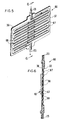
drug delivery device 40 which is adapted to be attached toformulator 30 as shown in Figures 1-3; - Figure 5 is a perspective view showing an
agent formulator 60 which can be used in anintravenous delivery system 10; and - Figure 6 is a cross-sectional view of
formulator 60 taken along line 6-6. - In the specification and the drawings, like parts in related Figures are identified by like numbers.
- Figure 1 illustrates an operative intravenous delivery system, generally designated by the numeral 10, showing the positioning of an
agent formulator 30 therein.System 10 comprises acontainer 12 that contains a fluid 13 suitable for intravenous administration, and an administration set, generally designated 14. The fluid 13 incontainer 12 will typically be a medical fluid, i.e., a sterile solution such as an aqueous solution of dextrose, saline, and/or electrolytes.Fluid 13 is a vehicle for intravenous administration of a pharmaceutical agent to a recipient.Container 12 is manufactured from glass or plastic, and is preferably of the no air-tube vacuum type and thus it is used with an administration set that has an air inlet filter. Other types of containers such as the air-tube vacuum type, or the non-vented type, can be used for the intended purpose. These alternative containers do not require an air filter in the administration set.Container 12 can be rigid, semi-rigid or flexible in structure, and it is usually adapted to be hung neck-down from a hanger 15 by ahandle 16 that connects or surroundscontainer 12. The neck ofcontainer 12 is covered by aclosure 17, generally made of rubber and air-tight. - Alternatively,
container 12 can take the form of an infusor or a syringe pump (not shown in the Figures), and in particular a portable infusor or syringe pump, of the kind known in this art. - Administration set 14 and
container 12 are interconnected by piercingclosure 17 with one end of ahollow spike 18 attached to or formed as a part of administration set 14.Spike 18 is equipped with aside air vent 19. The other end ofspike 18 is enlarged and fits snugly into adrip chamber 22.Drip chamber 22 traps air contained in theset 14 and facilitates adjusting the flow rate of intravenous fluid 13 fromcontainer 12 as the flow proceeds drop wise. The outlet at the bottom ofdrip chamber 22 is connected to a first segment oftubing 23 which fits intoagent formulator 30, the details of which are presented in Figures 2 and 3. A second segment oftubing 25 leads fromagent formulator 30 tobacterial filter 27. A third segment oftubing 29 extends fromfilter 27 to an infusion agent receptor site, terminating in an adapter-needle assembly 28 that is inserted into a vein of a warm-blooded animal 20, shown as a human arm. A piece oftape 21 holds adapter-needle assembly 28 firmly in place on the recipient's arm. The administration set can also include a pair of tubing clamps 24 and 26 located on either side offormulator 30 which may be used to govern or stop the flow of intravenous fluid through theintravenous delivery system 10. - In one embodiment of the present invention, a portion of the wall of
container 12 is comprised of a material 11 which is permeable to the beneficial agent contained within, and delivered by, thedelivery device 40. Thewall portion 11 forms a "drug delivery window" within the otherwise impermeable wall ofcontainer 12. During delivery of beneficial agent fromdevice 40, theIV fluid 13 must be in contact with the interior surface ofwall portion 11. Accordingly, thewall portion 11 is preferably located in a downstream portion of the wall ofcontainer 12 most preferably adjacent the neck ofcontainer 12. - As an alternative to, or in addition to the
drug delivery window 11 incontainer 12, anagent formulator 30 may be provided downstream from thecontainer 12.Agent formulator 30, as seen in Figures 2 and 3, comprises awall 32 forming achamber 34. At least a portion of thewall 32 is comprised of a material 36 which is permeable to the beneficial agent contained within, and delivered by, thedelivery device 40. Thewall portion 36 forms a drug delivery window, similar towall portion 11, within the otherwiseimpermeable wall 32 which may be formed of glass, plastic or the like. - As best shown in Figures 2 and 3, a
flow diverter 38 is provided within-chamber 34. Theflow diverter 38 is secured withinchamber 34 by supports 39. Preferably,formulator 30 has a cylindrical shape and thewall portion 36 extends around the entire circumference offormulator 30. Theflow diverter 38 also preferably has a roughly cylindrical shape. Theentire chamber 34 preferably remains filled with the flowingIV fluid 13 to ensure that the entire interior surface ofwall portion 36 is in contact with the flowingIV fluid 13. Theflow diverter 38 provides two important functions in theformulator 30 of the present invention. First, theflow diverter 38 diverts the flow of IV fluid in the direction shown by the arrows in Figure 2, i.e., along the interior surface ofwall portion 36. Secondly, theflow diverter 38 minimizes the dead volume withinformulator 30. Those skilled in the art will appreciate that theflow diverter 38 forces the IV fluid to flow in a relatively constricted space between theflow diverter 38 and thewall portion 36, thereby enabling a greater percentage of theIV fluid 13 to contact the interior surface ofwall portion 36. - The efficiency of drug transfer into the
IV fluid 13 is greatly enhanced by theflow diverter 38.Flow diverter 38 creates a higher liquid flow velocity (for any given liquid volumetric flow rate) along the interior surface ofwall portion 36 which helps eliminate any stagnant fluid layer. In accordance with well known flow principles, the thickness of the stagnant fluid layer along the walls ofchamber 34 decreases as the fluid flow velocity throughchamber 34 increases. This creates several beneficial effects. First, there is a trend to reduce the number of air or gas bubbles which might otherwise form on the interior surface of thewall portion 36 and which reduce the effective area of the wall portion through which drug can be transfered into the IV fluid. The higher fluid flow velocity also promotes higher drug transfer rates by maintaining a lower drug concentration in the IV fluid adjacent thewall portion 36. - An alternative embodiment of an agent formulator is shown in Figures 5 and 6 and is designated by 60. Like
formulator 30,formulator 60 is also connectable to an intravenous administration set by connecting toinlet tubing 23 andoutlet tubing 25.Agent formulator 60 comprises awall 32 and awall portion 36. Thedelivery device 40 is adapted to be secured towall portion 36.Wall portion 36 is comprised of a material which is permeable to the beneficial agent contained within, and delivered by, thedelivery device 40. Thewall portion 36 forms a drug delivery window, similar to wall portion 11 (Figure 1) and wall portion 36 (Figure 2), within the otherwiseimpermeable wall 32 which is preferably formed of a moldable plastic, e.g., polyethylene terephthalate. - As shown in Figures 5 and 6,
wall 32 is molded to form atortuous flow path 67 defined by a plurality offlow diverters 68.Wall portion 36 may be bonded to thewall 32 using heat and pressure according to well known methods. Thus, theIV fluid 13 flows along the interior surface ofwall portion 36 as shown by the arrows. Thetortuous flow path 67 achieves the same benefits of higher liquid flow velocity, elimination of stagnant fluid layers, reduction in air or gas bubbles and higher drug transfer rates mentioned above with respect to flow diverter 38 (Figures 2 and 3). - The
wall portions device 40 to diffuse therethrough but which prevent convective IV fluid flow therethrough. The composition ofwall portions device 40. In general, thewall portions device 40 to diffuse through the wall portion and into the interior ofcontainer 12 and/or intochamber 34. Representative polymers for formingwall portions - When the
device 40 delivers a hydrophilic drug, thewall portions - When
device 40 delivers a lipophilic drug, thewall portions - When
device 40 delivers a polypeptide, protein or other macromolecule, thewall portions container 12 and/or thechamber 34. In general, microporous materials having pore sizes in the above mentioned range will allow water molecules from the parenteral fluid to diffuse into the membrane. In some cases, the exterior of thewall portions wall portions microporous wall portions wall portions delivery device 40 may utilize a carrier which is immiscible in water. In such a case, the beneficial agent is suspended in a water-immiscible fluid carrier (e.g., an oil). When the oil-based carrier enters the pores of the microporous membrane, the pores will repel any water-based parenteral fluid which helps prevent convective losses through thewall portions - Examples of suitable microporous materials include Celgard® (a microporous polypropylene film sold by Celanese Chemical Co. of Dallas, TX) cellophane, glass frits, vycor glass, porous glass and microporous membranes of the type utilized in known elementary osmotic pumps. Of these, porous glass is most preferred.
- Selection of polymers for forming
wall portions 
wherein: - Q₁
- = cumulative amount of drug in the downstream solvent in micrograms at t₁;
- Q₂
- = cumulative amount of drug in solvent in micrograms at t₂;
- t₁
- = elapsed time to first sample, i.e., Q₁;
- t₂
- = elapsed time to second sample, i.e., Q₂;
- A
- = area of film in cm²;
- C
- = concentration of drug in saturated solution; and
- h
- = thickness of film in cm.
-
Wall portions wall portions - In an alternative embodiment of the invention, the agent
permeable wall portion 36 may be formed in situ. For example,wall 32 offormulator 30 may be composed of a polymer, such as polyvinylchloride, a polyester or a polyurethane, which is initially impermeable to the passage of drug or agent. Aportion 36 ofwall 32 can be treated with a permeability enhancing agent, such as a plasticizer or a transdermal permeation enhancer, in order to form a drugpermeable wall portion 36 in situ. The plasticizer may be delivered concurrently with the drug or agent fromdelivery device 40. For example, when thewall 32 is formed of polyvinylchloride,delivery device 40 contains both drug and a plasticizer. Thereafter the drug is delivered bydevice 40 throughwall portion 36 intochamber 34. - When the
wall portions container 12 or withinchamber 34. The porous or grid-like polymer structure should allow the IV fluid to contact the interior surface ofwall portions wall portions wall portions drug delivery device 40 thereon. - In its broadest sense, the
drug delivery device 40 comprises a beneficial agent-containing reservoir which can be releasably attached to the exterior surface of thewall portion 11 and/or 36. Typically, the reservoir comprises a polymeric matrix having a drug or other beneficial agent dispersed therein. The reservoir may be releasably attached to thewall portions 11 and/or 36 using tape, clamps, adhesives or other conventional attaching means. Mechanical attaching means are preferred where the beneficial agent delivered by the device is incompatible with adhesives. In cases where the beneficial agent is adhesive-compatible, the reservoir preferably incorporates a releasable contact adhesive, or has a releasable contact adhesive layer coated on one side thereof, so that the reservoir is itself releasably adhered to thewall portion 11 and/or 36. - The
agent delivery device 40 used in the present invention is not limited to any particular type or structure. Many suitable devices are known in the art and have generally been used in applications wherein a drug or other beneficial agent is administered transdermally. Examples of suitableagent delivery devices 40 may be found for example in U.S. Patents Nos. 3,536,809; 3,598,122; 3,598,123; 3,787,571; 3,699,963; 3,731,683; 3,734,097; 3,742,951; 3,797,494; 3,964,482; 3,996,934; 4,031,894; 4,060,084; and others to name just a few. The teachings of the above listed patents concerning the relevant structures of the drug delivery devices and the particular drugs which may be suitably administered using these devices are incorporated herein by reference. - A preferred
drug delivery device 40 is illustrated in Figure 4.Device 40 is a multilaminate system comprised of animpermeable backing layer 42, adrug reservoir 48 and anadhesive layer 50.Devite 40 also includes a permeation enhancer-containing layer 44 (e.g., an ethanol gel layer) and arate controlling membrane 46. Astrippable release liner 52, adapted to be removed prior to application, is normally included in the packaged product. - The
drug reservoir 48 may be comprised of a polymeric matrix or carrier having the drug/beneficial agent to be delivered, dispersed throughout. The polymer matrix stores and releases the beneficial agent/drug by diffusion or by osmotic action to wallportion 11 and/or 36. Representative polymers for forming the matrix may be selected from homopolymers, copolymers, cross-linked polymers, diffusion polymers and microporous polymers. Examples of suitable polymers include acrylic polymers and copolymers of methacrylate, ethylacrylate, ethylmethacrylate, and methylmethacrylate; homopolymers and copolymers including vinylchloride-vinylacetate copolymer; chlorinated vinyl chloride; polyethylene; polypropylene; ethylene-propylene copolymer; chlorinated polyethylene; ethylene-vinyl acetate copolymer (EVA) of the type described in U.S. Patent No. 4,144,317; styrene-butadiene copolymer; acrylonitrile-styrene-butadiene terpolymer; polyvinylidene chloride; vinylchloride-acrylonitrile copolymer; vinylchloride-vinylidene chloride copolymer; vinylidenechloride-acrylate ester copolymer; polybutylene terephthalate; vinylchloride-acrylate ester copolymer; cross-linked polyvinyl acetals such as cross-linked polyvinyl formal; cross-linked polyvinyl acetal and cross-linked polyvinyl butyral; polyethers; polyesters; sparingly cross-linked polyesters; polyurethane; polyamide; chlorosulfonated polyolefins; polyolefins; polybutadiene; polyisoprene; polysilicone; natural and synthetic rubbers; and the like. The polymers are known in The Handbook of Common Polymers, by Scott et al., (1971), published by CRC Press, Cleveland OH; in Modern Plastics Encyclopedia, (1979), published by McGraw-Hill Inc., New York, NY; and in Handbook of Plastics and Elastomers, by Harper, (1976), published by McGraw-Hill Inc., San Francisco, CA. - The
drug reservoir 48 may contain the drug alone or it may contain the drug along with one or more permeation enhancers. The drug/beneficial agent should either itself be soluble in the parenteral fluid or be capable of being solubilized using adjuvants such as surfactants and/or co-ions. The amount of drug in thereservoir 48 will depend upon the rate at which the drug is delivered from the system and the intended duration of therapy. The amount of drug/beneficial agent inreservoir 48 generally will be about 0.1% to 80% by weight, with a more preferred amount of 5% to 50% by weight. Thedevice 40 can be manufactured for delivering beneficial amounts of a drug over a prolonged period from about 0.5 hours to several days or longer, with a more preferred period of about 4 to 50 hours. Thedevice 40 used in the present invention releases from 10 ng to 750 mg per hour, or higher. Thereservoir 48 may also include diluents, stabilizers, vehicles, gelling agents, and the like. - The backing
member 42 serves the purpose of insuring unidirectional passage of drug throughwall portion 11 and/or 36 intocontainer 12 and/orchamber 34, and also of providing support for the system, where needed. The backing layer can be flexible or nonflexible and suitable materials include, without limitation, cellophane, cellulose acetate, ethylcellulose, plasticized vinylacetate-vinylchloride copolymers, polyethylene terephthalate, nylon, high and low density polyethylene, polypropylene, metalized polyester films, polyvinylidene chloride, coated flexible fibrous backings such as paper and cloth and aluminum foil. Such backings can be in the form of precast films or fabrics which are bonded to the reservoir by heat or adhesives and can be coated onto thereservoir 48. - The
device 40 is held in place onwall portion 11 and/or 36 by means of an in-line pharmaceutically acceptable contactadhesive layer 50. Drug and/or a permeation enhancer may also be incorporated into theadhesive layer 50. The composition and thickness of theadhesive layer 50 are preferably such that it does not constitute a significant permeation barrier to the drug or the permeation enhancer, if one is present. Any pharmaceutically acceptable contact adhesive may be used. Representative adhesives include mixtures of 2-cyanoacrylate and dimethyl methylenemalonate, monomeric ester of alpha-cyanoacrylic acid, cross-linked copolymer of dimethylaminoethylmethacrylate and an alkyl acrylate, adhesive compositions comprising a hydrocolloid gum, polyisobutylene and cross-linked dextran, silicone medical adhesives, mineral oil-polyisobulylene adhesives, contact adhesives such as those disclosed in U.S. Patent Nos. 3,797,494 and 4,031,894, and the like. The adhesive optionally can contain a rheological agent that imparts thixotropic characteristics to the adhesive, aids in increasing its cohesiveness and bond strength, imparts slump control, maintains thedelivery device 40 in contact withwall portion 11 and/or 36, and lets it be easily removed therefrom at the end of the delivery period. The rheological agents useful for this purpose are silicon compounds such as fumed silica. - The adhesive may also optionally contain a surfactant which allows better contact between the surface of the
delivery device 40 and the exterior surface ofwall portion 11 and/or 36. - If necessary or desirable, known permeation enhancers, such as ethanol or glycerol monolaurate, may be contained either within the separate layer 44 (if one is present), in the
adhesive layer 50, in thedrug reservoir 48, or in any combination of these. - Most preferably,
device 40 includes arate controlling membrane 46 which is effective to control the rate at which the beneficial agent is delivered fromreservoir 48 intocontainer 12 and/orchamber 34. Whendevice 40 contains arate controlling membrane 46, thewall portions rate controlling membrane 46 may be comprised of permeable, semipermeable or microporous materials which are known in the art to control the flux rate of the drug out of thedevice 40. Suitable materials include polyvinylacetate and ethylene vinylacetate polymers. When arate controlling membrane 46 is present indevice 40, the beneficial agent delivery rate is determined by thedelivery device 40, and not by thewall portions - However, it is also within the scope of the present invention to utilize a
delivery device 40 containing norate controlling membrane 46. When norate controlling membrane 46 is provided indelivery device 40, thewall portion 11 and/or 36 should be comprised of a material which is effective to control the rate at which the beneficial agent is delivered intocontainer 12 and/orchamber 34. When thewall portion 36 itself controls the rate at which the beneficial agent is delivered intochamber 34, the formulator 30 will be relatively drug specific (i.e., the formulator will only be suitable to control the rate of delivery of a specified drug or class of drugs. Likewise, when thewall portion 11 itself controls the rate at which the beneficial agent is delivered into thecontainer 12, thecontainer 12 will be relatively drug specific (i.e., the IV fluid container will only be suitable to control the rate of delivery of a specified drug or class of drugs.). - On the other hand, when the
wall portion 36 provides minimal resistance/control over the drug flux therethrough, the formulator 30 can be used with a wide range of drugs. Similarly, when thewall portion 11 provides minimal resistance/control over the drug flux therethrough, thecontainer 12 can be used with a wide range of drugs. However, in this second configuration, the control of drug delivery should be provided by thedrug delivery device 40. This is preferred since transdermal type drug delivery devices are generally manufactured to deliver a specific drug at a specific drug delivery rate. - The size (e.g., the surface area of
adhesive layer 50 which is in contact withwall portion 11 and/or 36) of thedevice 40 can typically vary from less than 1 cm² to greater than 200 cm². Anaverage device 40 however, will typically have a size within the range of about 5-50 cm². - Embodiments of
device 40 in which the drug and permeation enhancer supplies are separate (such as that illustrated in Figure 4) may be advantageous or necessary in instances where formulation or storage of the drug and the enhancer in contact with each other is impractical or undesirable or where separation of the drug and the enhancer facilitates selection of the rate controlling membrane. - The size (i.e., the surface area) of
wall portions delivery device 40, and preferably large enough to accommodate two ormore delivery devices 40. By makingwall portions delivery devices 40, it is possible to simultaneously deliver more than one beneficial agent into theIV fluid 13. Likewise, it is also possible to deliver a single beneficial agent at a delivery rate which is a multiple (e.g., 2x, 3x, 4x, etc.) of the delivery rate achieved by a single delivery device 40 (e.g., by adhering 2, 3, 4, etc.identical devices 40 to wallportions 11 and/or 36). - Important advantages achieved by the
container 12 and theformulator 30 of the present invention include (1) easy adjustment of the beneficial agent delivery rate, (2) easily changing the type of beneficial agent delivered, (3) it is unnecessary for a nurse or a the beneficial agent delivery rate, (2) easily changing the type of beneficial agent delivered, (3) it is unnecessary for a nurse or a pharmacist to preformulate the drug or other beneficial agent and (4) the drug or other beneficial agent has a longer stable shelf-life since the drug is maintained in a solid, rather than in solution, form. For instance, if it is desired to increase the rate of delivery of a beneficial agent (e.g., an antibiotic) into the flowingIV fluid 13, one can simply select a suitableantibiotic delivery device 40 with a specified delivery rate. Furthermore, if it is desired to either double, triple or quadruple the delivery rate of this particular antibiotic, it is only necessary to apply 2, 3, or 4delivery devices 40, respectively, to thewall portions 11 and/or 36. - Likewise, if instead of delivering an antibiotic it is desired to deliver an anti-cancer agent into the flowing IV fluid, it is only necessary to remove the antibiotic-containing
drug delivery device 40 and replace it with an anti-cancer drug-containing delivery device. - Because the
agent delivery devices 40 are attached to the exterior surfaces ofcontainer 12 andformulator 30, there is no danger of contamination of the flowing IV fluid. Thus, changing the type of drug delivered or the drug delivery rate does not require time consuming sterilization procedures. This is especially important when utilizing devices which deliver protein formulations since proteins are sensitive to heat sterilization and have a tendency to denature when heated. - The invention is further illustrated by the following examples.
- A nitroglycerin ("NG")/triethyl citrate reservoir composition comprising a silicone medical fluid carrier gelled with silica, having NG on lactose uniformly dispersed therethrough and triethyl citrate (Citroflex A6, sold by Morflex Inc. of Greensboro, NC) absorbed in a particulate carrier is fabricated by placing 5 kg of silicone medical fluid having a viscosity of about 100 centistokes and 175 grams of colloidal silicon dioxide in a high energy mixing vessel and blending to produce a gelled silicone fluid. 200 Grams of Accurel® porous polypropylene available from ARMAK Company is placed in a separate vessel and approximately 1200 grams of Citroflex A6 is added with stirring to produte an essentially dry flowable powder which on visual observation appears to have absorbed substantially all of the Citroflex. 5 kg of nitroglycerin-lactose (10 wt % nitroglycerin) and the Citroflex loaded porous polypropylene is placed in the original high energy mixing vessel and mixed until a homogeneous blend is obtained. A form-fill-seal pouching machine is used to pouch the NG-Citroflex gel so formed between an impermeable backing member comprising a medium density polyethylene/aluminized polyester/ethylene vinyl acetate multilaminate (Medpar® 1006 available from Minnesota Mining & Manufacturing Company) peripherally thermosealed to the rate controlling membrane layer of a trilaminate film consisting of a release liner layer formed from polyester film coated with a film release agent, an adhesive layer formed of silicone medical adhesive and a release rate controlling membrane layer formed from a 1 mil thick ethylene vinyl acetate (12% VA) membrane. Devices are fabricated having an NG/Citroflex releasing surface area of approximately 5 cm².
- One of the devices is adhered to an IV drug formulation chamber having the same shape and configuration as the formulation chamber illustrated in Figure 5.
Wall portion 36 is formed of polyvinylchloride which is initially unplasticized and impermeable to the passage of nitroglycerin. The thickness ofwall portion 36 is 5 mils. Once the drug delivery device is attached to the wall of the drug formulation chamber, the device delivers Citroflex A6 into the polyvinylchloride wall. Citroflex A6 is a plasticizer for polyvinylchloride. After a period of time, the portion of the chamber wall which is immediately adjacent to the drug delivery device becomes plasticized and drug permeable. Thereafter, nitroglycerine is delivered by the device through the drug permeable wall portion and into the IV fluid within the drug formulation chamber. - A monolithic transdermal device is prepared by melt blending 33 parts ethylene vinyl acetate (40% VA) with 32 parts Staybelite Ester No. 5, 5 parts estradiol valerate and 25 parts triethyl citrate (Citroflex A4 sold by Morflex Inc. of Greensboro, NC). The mixture is extruded and calendared to a thickness of 12 mils between an occlusive backing film of the type described in Example I and a strippable release liner film. Individual devices are rotary die cut with an area of 50 cm².
- One of the devices is adhered to an IV drug formulation chamber of the type described above in Example I. Once the drug delivery device is attached to the wall of the drug formulation chamber, the device delivers Citroflex A4 into the polyvinylchloride wall. Citroflex A4 is a plasticizer for polyvinylchloride. After a period of time, the portion of the chamber wall which is immediately adjacent to the drug delivery device becomes plasticized and drug permeable. Thereafter, estradiol valerate is delivered by the device through the drug permeable wall portion and into the IV fluid within the drug formulation chamber.
- Other benefits and advantages of the invention will become apparent to those skilled in the art. While the preferred embodiments of the invention have been selected for illustration in the drawings and have been described in detail herein, those skilled in the art will appreciate that various modifications, changes, additions and omissions from the illustrated embodiments can be made without departing from the spirit and scope of the invention, as defined in the appended claims.
By determining the slope of the plot, i.e., [Q₁ - Q₂/t₁ - t₂] and solving the equation using the known or measured values of A, C and h, the permeability coefficient, P, in cm²/time of the film for a given drug is readily determined. The procedures used to determine the rate of release through the polymer can be ascertained easily by standard techniques known to the art as recorded in J. Pharm. Sci., Vol. 52, pp 1145-49, (1963); ibid, Vol. 53, pp 798-802, (1964); ibid, Vol. 54, pp 1459-64, (1965); ibid, Vol., 55, pp 840-43 and 1224-39, (1966); Encyl. Polymer Sci. Technol., Vol. 5 & 9, pp 65-82 and 794-807, (1986); the references cited therein, and the like.
Claims (38)
- An agent formulator (30) for use in parenteral fluid delivery system, the formulator including a chamber (34) having fluid inlet (23) and outlet (25) means to maintain a continuous flow of the parenteral fluid therethrough, the chamber having a wall portion (36) comprised of a material that (1) is permeable to a beneficial agent to be delivered into the fluid and (2) prevents convective flow of parenteral fluid therethrough; and a flow distributor (38) within the formulator for distributing the flow of parenteral fluid along an interior surface of the wall portion; the formulator being characterised by:
an agent delivery device (40) attached to an accessible exterior surface of the wall portion, the delivery device comprising a reservoir (48) containing the beneficial agent, the reservoir being releasably attached to the exterior surface of the wall portion;
wherein in operation, the fluid flowing through the chamber is distributed by the flow distributor along the interior surface of the wall portion, causing the agent to be delivered from the device through the wall portion and into the flowing fluid, the agent being delivered at a rate which is controlled substantially by the formulator and which is substantially independent of volumetric flow rate of the fluid flowing through the chamber. - The formulator of claim 1, including a container (12) of a pharmaceutically acceptable parenteral fluid (13) that is a carrier for the agent and a parenteral fluid administration set (10) connected to the container for permitting the fluid to flow from the container through the administration set to an animal, the set comprising a drip chamber (22), tubing (23) extending from the drip chamber to the animal, and the agent formulator (30) connected into the tubing such that the intravenous fluid flows through the formulator.
- The formulator of claim 1 or 2, wherein the delivery device (40) comprises a laminate including: a backing member (42), a middle reservoir (48) containing the beneficial agent, and an adhesive surface (50) adapted to releasably adhere to the exterior surface of the wall portion (36).
- The formulator of any preceding claim, wherein the agent is a drug and the parenteral fluid is an intravenously acceptable fluid.
- The formulator of any preceding claim, wherein the delivery device contains a membrane layer (46) which controls the rate at which the delivery device delivers the beneficial agent into the chamber (34).
- The formulator of claim 1 or 2, wherein the chamber (34) is cylindrically shaped and said wall portion (36) extends around the entire circumference of the chamber (34).
- The formulator of claim 6, wherein the flow distributor comprises a cylindrically shaped member fixedly positioned within the chamber (34).
- The formulator of any preceding claim, wherein the flow distributor (38) forms a tortuous flow path (67) along the wall portion within the chamber (34).
- The formulator of any preceding claim, wherein the flow distributor (38) channels the parenteral fluid into a constricted space between the flow distributor (38) and the wall portion (36).
- The formulator of any preceding claim, wherein said chamber (34) contains an air release vent and is simultaneously employed as a drip chamber for providing a measurable number of drops per minute of the fluid, the fluid transporting the agent delivered by the delivery device to an agent receptor site.
- The formulator of any preceding claim, wherein the rate at which the agent is delivered into the chamber is controlled by the wall portion.
- The formulator of any preceding claim, wherein the wall portion (36) is comprised of a solution-diffusion membrane.
- The formulator of any of claims 1 to 11 wherein the wall portion (36) is comprised of a microporous membrane.
- The formulator of any preceding claim wherein the wall portion (36) is initially impermeable to the beneficial agent and the wall portion (36) is made permeable to the agent by application of a permeability enhacing agent thereto.
- The formulator of claim 14, wherein the permeability enhancing agent is delivered to the wall portion (36) the agent delivery device.
- The formulator of claim 14, wherein the permeability effacing agent comprises a plasticizer of the material forming the wall portion (36).
- The formulator of any preceding claim, wherein the wall portion (36) has a size and shape enabling a plurality of agent delivery devices to be attached to the exterior surface thereof.
- The formulator of any preceding claim, wherein the delivery device (40) is releasably adhered to the wall portion.
- The formulator of any preceding claim, wherein the agent is osmotically active.
- The formulator of any preceding claim, wherein the agent comprises a drug and an osmotically active solute.
- The formulator of any of claims 2 to 20, wherein a skin piercing means (28) is connected to the tubing for administering the agent to the animal.
- The formulator of any preceding claim adapted for use with a human and the agent comprises a drug.
- The formulator of any preceding claim, wherein the parenteral fluid is an intravenously acceptable fluid.
- A parenteral fluid reservoir container (10) for use in a parenteral fluid delivery system, the container comprising a chamber (12) for containing the parenteral fluid (13) and having fluid outlet means (17) to provide a continuous flow of the parenteral fluid out of the container, characterised by:
the chamber having a wall portion (11) comprised of a material that (1) is permeable to a beneficial agent to be delivered into the fluid and (2) prevents convective flow of parenteral fluid therethrough; and
an agent delivery device (40) attached to an accessible exterior surface of the wall portion, the delivery device comprising a reservoir (48) containing the beneficial agent, the reservoir being releasably attached to the exterior surface of the wall portion;
wherein in operation, the fluid in the container contacts an interior surface of the wall portion, causing the agent to be delivered from the device through the wall portion and into the fluid, the agent being delivered at a rate which is controlled substantially by the wall portion or by the agent delivery device and which is substantially independent of volumetric flow rate of the fluid flowing out of the container. - The container of claim 24, wherein the delivery device comprises a laminate including a backing member (42), a middle reservoir (48) containing the beneficial agent, and an adhesive surface (50) adapted to releasably adhere to the external surface of the wall portion.
- The container of claim 24 or 25, wherein the parental fluid is an intravenously acceptable fluid.
- The container of any of claims 24 to 26, wherein the container is adapted for use with a human and the agent comprises a drug.
- The container of any of claims 24 to 27, wherein the rate at which the agent is delivered into the chamber (12) is controlled by the wall portion (11).
- The container of any of claims 24 to 28, wherein the delivery device (40) contains a membrane layer (46) which controls the rate at which the delivery device delivers the beneficial agent into the chamber.
- The container of any of claims 24 to 29, wherein the wall portion (11) is comprised of a solution-diffusion membrane.
- The container of any of claims 24 to 29, wherein the wall portion (11) is comprised of a microporous membrane.
- The container of any of claims 24 to 29, wherein the wall portion (11) is initially impermeable to the beneficial agent and the wall portion (11) is made permeable to the agent by application of a permeability enhancing agent thereto.
- The container of any of claims 24 to 32, wherein the permeability enhancing agent is delivered to the wall portion (11) by the agent delivery device.
- The container of claim 33, wherein the permeability enhacing agent comprises a plasticizer of the arterial forming the wall portion (11).
- The container of any of claims 24 to 34, wherein the wall portion (11) has a size and shape enabling a plurality of agent delivery devices to be attached to the exterior surface thereof.
- The container of any of claims 24 to 35, wherein the delivery device is releasably adhered to the wall portion (11).
- The container of any of claims 24 to 36, wherein the agent is osmotically active.
- The container of any of claims 24 to 37, wherein the agent comprises a drug and an osmotically active solute.
Applications Claiming Priority (2)
| Application Number | Priority Date | Filing Date | Title |
|---|---|---|---|
| US311906 | 1989-02-15 | ||
| US07/311,906 US4969871A (en) | 1989-02-15 | 1989-02-15 | Intravenous system for delivering a beneficial agent |
Publications (2)
| Publication Number | Publication Date |
|---|---|
| EP0458879A1 EP0458879A1 (en) | 1991-12-04 |
| EP0458879B1 true EP0458879B1 (en) | 1993-06-02 |
Family
ID=23209012
Family Applications (1)
| Application Number | Title | Priority Date | Filing Date |
|---|---|---|---|
| EP90903659A Expired - Lifetime EP0458879B1 (en) | 1989-02-15 | 1990-02-14 | Intravenous system for delivering a beneficial agent |
Country Status (12)
| Country | Link |
|---|---|
| US (2) | US4969871A (en) |
| EP (1) | EP0458879B1 (en) |
| AT (1) | ATE90000T1 (en) |
| AU (1) | AU623983B2 (en) |
| CA (1) | CA2009984A1 (en) |
| DE (1) | DE69001812T2 (en) |
| DK (1) | DK0458879T3 (en) |
| ES (1) | ES2041174T3 (en) |
| GR (1) | GR1000496B (en) |
| NZ (1) | NZ232524A (en) |
| PT (1) | PT93152A (en) |
| WO (1) | WO1990009201A1 (en) |
Families Citing this family (50)
| Publication number | Priority date | Publication date | Assignee | Title |
|---|---|---|---|---|
| US5104390A (en) * | 1988-09-01 | 1992-04-14 | Alza Corporation | Fluid receiving receptacle comprising biocide delivery system contacting outside of receptacle |
| US4969871A (en) * | 1989-02-15 | 1990-11-13 | Alza Corporation | Intravenous system for delivering a beneficial agent |
| US5250028A (en) * | 1989-02-15 | 1993-10-05 | Alza Corporation | Intravenous system for delivering a beneficial agent using permeability enhancers |
| JPH02299663A (en) * | 1989-05-15 | 1990-12-11 | Unitika Ltd | Anti-infectious catheter |
| US5411480A (en) * | 1989-06-16 | 1995-05-02 | Science Incorporated | Fluid delivery apparatus |
| US5336188A (en) * | 1989-06-16 | 1994-08-09 | Science Incorporated | Fluid delivery apparatus having a stored energy source |
| AU3241393A (en) * | 1991-12-06 | 1993-06-28 | Edward Teeple Jr. | Method, apparatus for preparing and administering intravenous anesthesia infusions |
| RU2131273C1 (en) * | 1993-04-13 | 1999-06-10 | Сайенс Инкорпорейтед | Liquid delivery device |
| DE69529572T2 (en) * | 1994-11-10 | 2003-06-18 | Univ Kentucky Res Foundation L | IMPLANTABLE REFILLABLE DEVICE WITH CONTROLLED RELEASE FOR ADMINISTERING MEDICINAL SUBSTANCES DIRECTLY ON AN INNER PART OF THE BODY |
| US5841638A (en) * | 1996-02-15 | 1998-11-24 | L3 Communications | Stacked memory for flight recorders |
| IL121286A0 (en) * | 1997-07-11 | 1998-01-04 | Pets N People Ltd | Apparatus and methods for dispensing pet care substances |
| US6019750A (en) | 1997-12-04 | 2000-02-01 | Baxter International Inc. | Sliding reconstitution device with seal |
| US7425209B2 (en) | 1998-09-15 | 2008-09-16 | Baxter International Inc. | Sliding reconstitution device for a diluent container |
| AR021220A1 (en) | 1998-09-15 | 2002-07-03 | Baxter Int | CONNECTION DEVICE FOR ESTABLISHING A FLUID COMMUNICATION BETWEEN A FIRST CONTAINER AND A SECOND CONTAINER. |
| US6113583A (en) | 1998-09-15 | 2000-09-05 | Baxter International Inc. | Vial connecting device for a sliding reconstitution device for a diluent container |
| US6641556B1 (en) * | 1999-07-06 | 2003-11-04 | Respiratory Support Products, Inc. | Intravenous fluid heating system |
| US6723076B1 (en) | 2000-03-24 | 2004-04-20 | Michael Strobel | Animal drug delivery device |
| US6332467B1 (en) * | 2000-04-05 | 2001-12-25 | Lh Medical Products, Inc. | Feeding tube spike set with integrated Y-port |
| US6629949B1 (en) | 2000-05-08 | 2003-10-07 | Sterling Medivations, Inc. | Micro infusion drug delivery device |
| US6659982B2 (en) | 2000-05-08 | 2003-12-09 | Sterling Medivations, Inc. | Micro infusion drug delivery device |
| US20050277887A1 (en) * | 2000-05-08 | 2005-12-15 | Joel Douglas | Micro infusion drug delivery device |
| WO2002055136A2 (en) * | 2000-12-01 | 2002-07-18 | Nephros Therapeutics Inc | Intrasvascular drug delivery device and use therefor |
| US8775196B2 (en) | 2002-01-29 | 2014-07-08 | Baxter International Inc. | System and method for notification and escalation of medical data |
| US10173008B2 (en) | 2002-01-29 | 2019-01-08 | Baxter International Inc. | System and method for communicating with a dialysis machine through a network |
| US8234128B2 (en) | 2002-04-30 | 2012-07-31 | Baxter International, Inc. | System and method for verifying medical device operational parameters |
| US7018361B2 (en) | 2002-06-14 | 2006-03-28 | Baxter International Inc. | Infusion pump |
| US6997905B2 (en) | 2002-06-14 | 2006-02-14 | Baxter International Inc. | Dual orientation display for a medical device |
| US20030236489A1 (en) | 2002-06-21 | 2003-12-25 | Baxter International, Inc. | Method and apparatus for closed-loop flow control system |
| US7641851B2 (en) | 2003-12-23 | 2010-01-05 | Baxter International Inc. | Method and apparatus for validation of sterilization process |
| WO2007092735A2 (en) | 2006-02-02 | 2007-08-16 | Innovative Bio Therapies | An extracorporeal cell-based therapeutic device and delivery system |
| ITMO20060098A1 (en) * | 2006-03-24 | 2007-09-25 | Sidam Di Azzolini Graziano E C | SUPPORT DEVICE FOR BIO-MEDICAL FLUID CONTAINERS FOR PARENTERAL ADMINISTRATION, PARTICULARLY BOTTLES AND BOTTLES FOR MEDICAL FLUIDS, BLOOD OR SIMILAR |
| WO2010071692A2 (en) | 2008-06-18 | 2010-06-24 | Innovative Biotherapies, Inc. | Methods for enhanced propagation of cells |
| US10089443B2 (en) | 2012-05-15 | 2018-10-02 | Baxter International Inc. | Home medical device systems and methods for therapy prescription and tracking, servicing and inventory |
| US8057679B2 (en) | 2008-07-09 | 2011-11-15 | Baxter International Inc. | Dialysis system having trending and alert generation |
| US8554579B2 (en) | 2008-10-13 | 2013-10-08 | Fht, Inc. | Management, reporting and benchmarking of medication preparation |
| US8105269B2 (en) | 2008-10-24 | 2012-01-31 | Baxter International Inc. | In situ tubing measurements for infusion pumps |
| JP2010100009A (en) * | 2008-10-27 | 2010-05-06 | Canon Inc | Ink cartridge and sealing member |
| US8137083B2 (en) | 2009-03-11 | 2012-03-20 | Baxter International Inc. | Infusion pump actuators, system and method for controlling medical fluid flowrate |
| US8382447B2 (en) | 2009-12-31 | 2013-02-26 | Baxter International, Inc. | Shuttle pump with controlled geometry |
| US8567235B2 (en) | 2010-06-29 | 2013-10-29 | Baxter International Inc. | Tube measurement technique using linear actuator and pressure sensor |
| US10552577B2 (en) | 2012-08-31 | 2020-02-04 | Baxter Corporation Englewood | Medication requisition fulfillment system and method |
| SG11201503190RA (en) | 2012-10-26 | 2015-05-28 | Baxter Corp Englewood | Improved image acquisition for medical dose preparation system |
| EP2911641B1 (en) | 2012-10-26 | 2018-10-17 | Baxter Corporation Englewood | Improved work station for medical dose preparation system |
| EP3161778A4 (en) | 2014-06-30 | 2018-03-14 | Baxter Corporation Englewood | Managed medical information exchange |
| US11575673B2 (en) | 2014-09-30 | 2023-02-07 | Baxter Corporation Englewood | Central user management in a distributed healthcare information management system |
| US11107574B2 (en) | 2014-09-30 | 2021-08-31 | Baxter Corporation Englewood | Management of medication preparation with formulary management |
| WO2016090091A1 (en) | 2014-12-05 | 2016-06-09 | Baxter Corporation Englewood | Dose preparation data analytics |
| EP3265989A4 (en) | 2015-03-03 | 2018-10-24 | Baxter Corporation Englewood | Pharmacy workflow management with integrated alerts |
| CA2985719C (en) | 2015-06-25 | 2024-03-26 | Gambro Lundia Ab | Medical device system and method having a distributed database |
| WO2018114346A1 (en) | 2016-12-21 | 2018-06-28 | Gambro Lundia Ab | Medical device system including information technology infrastructure having secure cluster domain supporting external domain |
Family Cites Families (29)
| Publication number | Priority date | Publication date | Assignee | Title |
|---|---|---|---|---|
| US3536809A (en) * | 1969-02-17 | 1970-10-27 | Alza Corp | Medication method |
| US3598123A (en) * | 1969-04-01 | 1971-08-10 | Alza Corp | Bandage for administering drugs |
| US3797494A (en) * | 1969-04-01 | 1974-03-19 | Alza Corp | Bandage for the administration of drug by controlled metering through microporous materials |
| US3598122A (en) * | 1969-04-01 | 1971-08-10 | Alza Corp | Bandage for administering drugs |
| US3734097A (en) * | 1969-04-01 | 1973-05-22 | Alza Corp | Therapeutic adhesive tape |
| US3699963A (en) * | 1969-10-31 | 1972-10-24 | Alza Corp | Therapeutic adhesive patch |
| US3964482A (en) * | 1971-05-17 | 1976-06-22 | Alza Corporation | Drug delivery device |
| US3731683A (en) * | 1971-06-04 | 1973-05-08 | Alza Corp | Bandage for the controlled metering of topical drugs to the skin |
| US3996934A (en) * | 1971-08-09 | 1976-12-14 | Alza Corporation | Medical bandage |
| US3742951A (en) * | 1971-08-09 | 1973-07-03 | Alza Corp | Bandage for controlled release of vasodilators |
| US3787571A (en) * | 1971-11-11 | 1974-01-22 | Alza Corp | Trichloroethanol and trifluoroethanol topical and percutaneous steroid adsorption promoters |
| US4144317A (en) * | 1975-05-30 | 1979-03-13 | Alza Corporation | Device consisting of copolymer having acetoxy groups for delivering drugs |
| US4031894A (en) * | 1975-12-08 | 1977-06-28 | Alza Corporation | Bandage for transdermally administering scopolamine to prevent nausea |
| US4060084A (en) * | 1976-09-07 | 1977-11-29 | Alza Corporation | Method and therapeutic system for providing chemotherapy transdermally |
| US4511353A (en) * | 1981-07-13 | 1985-04-16 | Alza Corporation | Intravenous system for delivering a beneficial agent |
| US4740201A (en) * | 1981-10-09 | 1988-04-26 | Alza Corporation | Intravenous system for delivering a beneficial agent |
| US4552555A (en) * | 1981-07-31 | 1985-11-12 | Alza Corporation | System for intravenous delivery of a beneficial agent |
| US4857052A (en) * | 1981-07-13 | 1989-08-15 | Alza Corporation | Intravenous system for delivering a beneficial agent |
| US4439183A (en) * | 1981-10-09 | 1984-03-27 | Alza Corporation | Parenteral agent dispensing equipment |
| US4740103A (en) * | 1981-10-09 | 1988-04-26 | Alza Corporation | Intravenous system for delivering a beneficial agent |
| US4740197A (en) * | 1981-10-09 | 1988-04-26 | Alza Corporation | Intravenous system for delivering a beneficial agent via polymer delivery |
| US4741734A (en) * | 1981-10-09 | 1988-05-03 | Alza Corporation | Releasing means for adding agent using releasing means to IV fluid |
| US4740200A (en) * | 1981-10-09 | 1988-04-26 | Alza Corporation | Intravenous system for delivering a beneficial agent |
| US4534757A (en) * | 1982-06-14 | 1985-08-13 | Alza Corporation | Device for releasing active ingredient, insertable in a system of parenteral administering the ingredient |
| WO1984004036A1 (en) * | 1983-04-18 | 1984-10-25 | Baxter Travenol Lab | Articles and compositions providing antimicrobial effect during urinary drainage |
| US4533348A (en) * | 1983-07-29 | 1985-08-06 | Alza Corporation | In-line drug dispenser for use in intravenous therapy |
| DE3775830D1 (en) * | 1986-06-13 | 1992-02-20 | Alza Corp | ACTIVATING A TRANSDERMAL DRUG DELIVERY SYSTEM THROUGH MOISTURE. |
| US4871352A (en) * | 1987-12-07 | 1989-10-03 | Controlled Release Technologies, Inc. | Self-regulated therapeutic agent delivery system and method |
| US4969871A (en) * | 1989-02-15 | 1990-11-13 | Alza Corporation | Intravenous system for delivering a beneficial agent |
-
1989
- 1989-02-15 US US07/311,906 patent/US4969871A/en not_active Expired - Fee Related
-
1990
- 1990-02-14 EP EP90903659A patent/EP0458879B1/en not_active Expired - Lifetime
- 1990-02-14 AU AU51517/90A patent/AU623983B2/en not_active Ceased
- 1990-02-14 NZ NZ232524A patent/NZ232524A/en unknown
- 1990-02-14 CA CA002009984A patent/CA2009984A1/en not_active Abandoned
- 1990-02-14 PT PT93152A patent/PT93152A/en not_active Application Discontinuation
- 1990-02-14 DE DE9090903659T patent/DE69001812T2/en not_active Expired - Fee Related
- 1990-02-14 US US07/741,413 patent/US5160320A/en not_active Expired - Fee Related
- 1990-02-14 ES ES199090903659T patent/ES2041174T3/en not_active Expired - Lifetime
- 1990-02-14 AT AT90903659T patent/ATE90000T1/en not_active IP Right Cessation
- 1990-02-14 DK DK90903659.2T patent/DK0458879T3/en active
- 1990-02-14 WO PCT/US1990/000880 patent/WO1990009201A1/en active IP Right Grant
- 1990-02-14 GR GR900100104A patent/GR1000496B/en unknown
Also Published As
| Publication number | Publication date |
|---|---|
| GR1000496B (en) | 1992-07-30 |
| NZ232524A (en) | 1995-03-28 |
| US5160320A (en) | 1992-11-03 |
| DE69001812T2 (en) | 1993-09-23 |
| AU623983B2 (en) | 1992-05-28 |
| AU5151790A (en) | 1990-09-05 |
| ES2041174T3 (en) | 1993-11-01 |
| GR900100104A (en) | 1991-06-28 |
| US4969871A (en) | 1990-11-13 |
| ATE90000T1 (en) | 1993-06-15 |
| EP0458879A1 (en) | 1991-12-04 |
| CA2009984A1 (en) | 1990-08-15 |
| DK0458879T3 (en) | 1993-08-23 |
| PT93152A (en) | 1990-08-31 |
| WO1990009201A1 (en) | 1990-08-23 |
| DE69001812D1 (en) | 1993-07-08 |
Similar Documents
| Publication | Publication Date | Title |
|---|---|---|
| EP0458879B1 (en) | Intravenous system for delivering a beneficial agent | |
| AU635005B2 (en) | Intravenous system for delivering a beneficial agent | |
| US5250028A (en) | Intravenous system for delivering a beneficial agent using permeability enhancers | |
| JP2694984B2 (en) | Transdermal therapeutic device | |
| US4511353A (en) | Intravenous system for delivering a beneficial agent | |
| EP0059694A1 (en) | Drug administration device | |
| US4994031A (en) | Intravenous system for delivering a beneficial agent | |
| Sugibayashi et al. | Polymers for transdermal drug delivery systems | |
| US5069671A (en) | Intravenous medication | |
| US4740103A (en) | Intravenous system for delivering a beneficial agent | |
| US4740200A (en) | Intravenous system for delivering a beneficial agent | |
| WO1994021262A1 (en) | Device for the transdermal administration of alprazolam | |
| EP0637975B1 (en) | Fluid dispenser | |
| US4586922A (en) | Intravenous system for delivering a beneficial agent | |
| EP0252459A1 (en) | Compartmentalized transdermal delivery system | |
| US4740198A (en) | Method of administering intravenous drug using rate-controlled dosage form | |
| US4740201A (en) | Intravenous system for delivering a beneficial agent | |
| US5045059A (en) | Intravenous system for delivering a beneficial agent | |
| US4740197A (en) | Intravenous system for delivering a beneficial agent via polymer delivery | |
| Chandrasekaran et al. | Therapeutic systems and controlled drug delivery | |
| US4969872A (en) | Intravenous system for delivering a beneficial agent with delivery rate control via permeable surface area variance | |
| US4740199A (en) | Intravenous system for delivering a beneficial agent | |
| EP0251425A1 (en) | Article for administration of pharmacologically-active substances | |
| US4741735A (en) | Intravenous system for delivering a beneficial agent | |
| JPH04503466A (en) | Intravenous system for administering active agents |
Legal Events
| Date | Code | Title | Description |
|---|---|---|---|
| PUAI | Public reference made under article 153(3) epc to a published international application that has entered the european phase |
Free format text: ORIGINAL CODE: 0009012 |
|
| 17P | Request for examination filed |
Effective date: 19910724 |
|
| AK | Designated contracting states |
Kind code of ref document: A1 Designated state(s): AT BE CH DE DK ES FR GB IT LI LU NL SE |
|
| 17Q | First examination report despatched |
Effective date: 19920416 |
|
| GRAA | (expected) grant |
Free format text: ORIGINAL CODE: 0009210 |
|
| AK | Designated contracting states |
Kind code of ref document: B1 Designated state(s): AT BE CH DE DK ES FR GB IT LI LU NL SE |
|
| REF | Corresponds to: |
Ref document number: 90000 Country of ref document: AT Date of ref document: 19930615 Kind code of ref document: T |
|
| ITF | It: translation for a ep patent filed |
Owner name: JACOBACCI CASETTA & PERANI S.P.A. |
|
| REF | Corresponds to: |
Ref document number: 69001812 Country of ref document: DE Date of ref document: 19930708 |
|
| ET | Fr: translation filed | ||
| REG | Reference to a national code |
Ref country code: DK Ref legal event code: T3 |
|
| ITF | It: translation for a ep patent filed |
Owner name: DE DOMINICIS & MAYER S. |
|
| REG | Reference to a national code |
Ref country code: ES Ref legal event code: FG2A Ref document number: 2041174 Country of ref document: ES Kind code of ref document: T3 |
|
| EPTA | Lu: last paid annual fee | ||
| PLBE | No opposition filed within time limit |
Free format text: ORIGINAL CODE: 0009261 |
|
| STAA | Information on the status of an ep patent application or granted ep patent |
Free format text: STATUS: NO OPPOSITION FILED WITHIN TIME LIMIT |
|
| 26N | No opposition filed | ||
| EAL | Se: european patent in force in sweden |
Ref document number: 90903659.2 |
|
| PGFP | Annual fee paid to national office [announced via postgrant information from national office to epo] |
Ref country code: FR Payment date: 19970115 Year of fee payment: 8 |
|
| PGFP | Annual fee paid to national office [announced via postgrant information from national office to epo] |
Ref country code: DE Payment date: 19970117 Year of fee payment: 8 Ref country code: DK Payment date: 19970117 Year of fee payment: 8 |
|
| PGFP | Annual fee paid to national office [announced via postgrant information from national office to epo] |
Ref country code: AT Payment date: 19970120 Year of fee payment: 8 Ref country code: NL Payment date: 19970120 Year of fee payment: 8 |
|
| PGFP | Annual fee paid to national office [announced via postgrant information from national office to epo] |
Ref country code: CH Payment date: 19970122 Year of fee payment: 8 |
|
| PGFP | Annual fee paid to national office [announced via postgrant information from national office to epo] |
Ref country code: GB Payment date: 19970127 Year of fee payment: 8 |
|
| PGFP | Annual fee paid to national office [announced via postgrant information from national office to epo] |
Ref country code: BE Payment date: 19970128 Year of fee payment: 8 |
|
| PGFP | Annual fee paid to national office [announced via postgrant information from national office to epo] |
Ref country code: ES Payment date: 19970217 Year of fee payment: 8 Ref country code: LU Payment date: 19970217 Year of fee payment: 8 |
|
| PG25 | Lapsed in a contracting state [announced via postgrant information from national office to epo] |
Ref country code: LU Free format text: LAPSE BECAUSE OF NON-PAYMENT OF DUE FEES Effective date: 19980214 Ref country code: GB Free format text: LAPSE BECAUSE OF NON-PAYMENT OF DUE FEES Effective date: 19980214 Ref country code: AT Free format text: LAPSE BECAUSE OF NON-PAYMENT OF DUE FEES Effective date: 19980214 |
|
| PG25 | Lapsed in a contracting state [announced via postgrant information from national office to epo] |
Ref country code: SE Free format text: LAPSE BECAUSE OF NON-PAYMENT OF DUE FEES Effective date: 19980215 |
|
| PG25 | Lapsed in a contracting state [announced via postgrant information from national office to epo] |
Ref country code: ES Free format text: LAPSE BECAUSE OF EXPIRATION OF PROTECTION Effective date: 19980216 |
|
| PG25 | Lapsed in a contracting state [announced via postgrant information from national office to epo] |
Ref country code: FR Free format text: THE PATENT HAS BEEN ANNULLED BY A DECISION OF A NATIONAL AUTHORITY Effective date: 19980228 Ref country code: LI Free format text: LAPSE BECAUSE OF NON-PAYMENT OF DUE FEES Effective date: 19980228 Ref country code: BE Free format text: LAPSE BECAUSE OF NON-PAYMENT OF DUE FEES Effective date: 19980228 Ref country code: CH Free format text: LAPSE BECAUSE OF NON-PAYMENT OF DUE FEES Effective date: 19980228 |
|
| PG25 | Lapsed in a contracting state [announced via postgrant information from national office to epo] |
Ref country code: DK Free format text: LAPSE BECAUSE OF NON-PAYMENT OF DUE FEES Effective date: 19980302 |
|
| BERE | Be: lapsed |
Owner name: ALZA CORP. Effective date: 19980228 |
|
| PG25 | Lapsed in a contracting state [announced via postgrant information from national office to epo] |
Ref country code: NL Free format text: LAPSE BECAUSE OF NON-PAYMENT OF DUE FEES Effective date: 19980901 |
|
| GBPC | Gb: european patent ceased through non-payment of renewal fee |
Effective date: 19980214 |
|
| REG | Reference to a national code |
Ref country code: CH Ref legal event code: PL |
|
| EUG | Se: european patent has lapsed |
Ref document number: 90903659.2 |
|
| NLV4 | Nl: lapsed or anulled due to non-payment of the annual fee |
Effective date: 19980901 |
|
| PG25 | Lapsed in a contracting state [announced via postgrant information from national office to epo] |
Ref country code: DE Free format text: LAPSE BECAUSE OF NON-PAYMENT OF DUE FEES Effective date: 19981103 |
|
| REG | Reference to a national code |
Ref country code: FR Ref legal event code: ST |
|
| REG | Reference to a national code |
Ref country code: DK Ref legal event code: EBP |
|
| REG | Reference to a national code |
Ref country code: ES Ref legal event code: FD2A Effective date: 20000301 |
|
| PGFP | Annual fee paid to national office [announced via postgrant information from national office to epo] |
Ref country code: SE Payment date: 20040204 Year of fee payment: 15 |
|
| PGFP | Annual fee paid to national office [announced via postgrant information from national office to epo] |
Ref country code: IT Payment date: 20090218 Year of fee payment: 20 |