EP0459645A1 - Stack of sheet assemblies - Google Patents
Stack of sheet assemblies Download PDFInfo
- Publication number
- EP0459645A1 EP0459645A1 EP91304215A EP91304215A EP0459645A1 EP 0459645 A1 EP0459645 A1 EP 0459645A1 EP 91304215 A EP91304215 A EP 91304215A EP 91304215 A EP91304215 A EP 91304215A EP 0459645 A1 EP0459645 A1 EP 0459645A1
- Authority
- EP
- European Patent Office
- Prior art keywords
- sheet
- stack
- sheets
- edges
- assemblies
- Prior art date
- Legal status (The legal status is an assumption and is not a legal conclusion. Google has not performed a legal analysis and makes no representation as to the accuracy of the status listed.)
- Granted
Links
Images


Classifications
-
- B—PERFORMING OPERATIONS; TRANSPORTING
- B41—PRINTING; LINING MACHINES; TYPEWRITERS; STAMPS
- B41L—APPARATUS OR DEVICES FOR MANIFOLDING, DUPLICATING OR PRINTING FOR OFFICE OR OTHER COMMERCIAL PURPOSES; ADDRESSING MACHINES OR LIKE SERIES-PRINTING MACHINES
- B41L1/00—Devices for performing operations in connection with manifolding by means of pressure-sensitive layers or intermediaries, e.g. carbons; Accessories for manifolding purposes
- B41L1/20—Manifolding assemblies, e.g. book-like assemblies
- B41L1/22—Manifolding assemblies, e.g. book-like assemblies made up of single sheets or forms
- B41L1/24—Pads or books
-
- B—PERFORMING OPERATIONS; TRANSPORTING
- B41—PRINTING; LINING MACHINES; TYPEWRITERS; STAMPS
- B41L—APPARATUS OR DEVICES FOR MANIFOLDING, DUPLICATING OR PRINTING FOR OFFICE OR OTHER COMMERCIAL PURPOSES; ADDRESSING MACHINES OR LIKE SERIES-PRINTING MACHINES
- B41L1/00—Devices for performing operations in connection with manifolding by means of pressure-sensitive layers or intermediaries, e.g. carbons; Accessories for manifolding purposes
- B41L1/04—Devices for performing operations subsequent to manifolding, e.g. for separating single sheets or webs from single form sets, continuous manifold assemblies from carbons
- B41L1/08—Devices for performing operations subsequent to manifolding, e.g. for separating single sheets or webs from single form sets, continuous manifold assemblies from carbons on continuous manifold assemblies
- B41L1/12—Severing webs to obtain single sheets or forms, e.g. by cutting, by bursting
-
- B—PERFORMING OPERATIONS; TRANSPORTING
- B42—BOOKBINDING; ALBUMS; FILES; SPECIAL PRINTED MATTER
- B42D—BOOKS; BOOK COVERS; LOOSE LEAVES; PRINTED MATTER CHARACTERISED BY IDENTIFICATION OR SECURITY FEATURES; PRINTED MATTER OF SPECIAL FORMAT OR STYLE NOT OTHERWISE PROVIDED FOR; DEVICES FOR USE THEREWITH AND NOT OTHERWISE PROVIDED FOR; MOVABLE-STRIP WRITING OR READING APPARATUS
- B42D5/00—Sheets united without binding to form pads or blocks
- B42D5/003—Note-pads
-
- G—PHYSICS
- G09—EDUCATION; CRYPTOGRAPHY; DISPLAY; ADVERTISING; SEALS
- G09B—EDUCATIONAL OR DEMONSTRATION APPLIANCES; APPLIANCES FOR TEACHING, OR COMMUNICATING WITH, THE BLIND, DEAF OR MUTE; MODELS; PLANETARIA; GLOBES; MAPS; DIAGRAMS
- G09B29/00—Maps; Plans; Charts; Diagrams, e.g. route diagram
-
- Y—GENERAL TAGGING OF NEW TECHNOLOGICAL DEVELOPMENTS; GENERAL TAGGING OF CROSS-SECTIONAL TECHNOLOGIES SPANNING OVER SEVERAL SECTIONS OF THE IPC; TECHNICAL SUBJECTS COVERED BY FORMER USPC CROSS-REFERENCE ART COLLECTIONS [XRACs] AND DIGESTS
- Y10—TECHNICAL SUBJECTS COVERED BY FORMER USPC
- Y10T—TECHNICAL SUBJECTS COVERED BY FORMER US CLASSIFICATION
- Y10T428/00—Stock material or miscellaneous articles
- Y10T428/14—Layer or component removable to expose adhesive
Definitions
- the present invention relates to stacks of sheet assemblies, each of which sheet assemblies comprises at least two sheets adhered together along at least one edge, the stacks being so constructed that individual sheet assemblies may be removed from the stack.
- the present invention provides a stack of sheet assemblies that are easily removed from the stack and applied to a substrate, and require no liner or use of sheets of different sizes in the stack to afford such removal.
- a stack of sheet assemblies each of which sheet assemblies comprises first and second sheets each having front and rear major surfaces and first and second opposite edges, a first layer of adhesive adhering a portion of the rear surface of the first sheet adjacent the first edge of the first sheet to the front surface of the second sheet adjacent the first edge of the second sheet with the first edges generally aligned, the first layer of adhesive extending a first predetermined distance from the first edges toward the second edges of the sheets, and a second layer of pressure sensitive adhesive on the rear surface of the second sheet.
- the second layer of pressure sensitive adhesive comprises a first portion adhering the rear surface of the second sheet of the sheet assembly to the front surface of the first sheet on the sheet assembly beneath it in the stack within the first distance from the first edge.
- the sheet assemblies also include release means for providing first adhesion zones between the front surfaces of the first sheets and the rear surfaces of the second sheets of the sheet assemblies in the stack, the first adhesion zones extending about the first predetermined distance from the first edges toward the second edges of the sheets and providing a release force between the first portions of the second layers of adhesive and the front surfaces of the adjacent first sheets in the stack which is lower than the release force of the first layers of adhesive to the first and second sheets to afford easy initiation of peeling of the uppermost sheet assembly from the adjacent sheet assembly in the stack along the first adhesion zone by pulling on the first sheet of the uppermost sheet assembly on the stack.
- edges of the second layers of pressure sensitive adhesive adjacent the second edges of the sheets are spaced toward the first edges of the sheets from the edges of the first layers of pressure sensitive adhesive adjacent the second edges of the sheets so that movement of the second edge of the first sheet of the uppermost sheet assembly in the stack away from the second edge of the second sheet of that uppermost sheet assembly will initiate peeling of its second layer of pressure sensitive adhesive away from the adjacent sheet assembly in the stack.
- the second layers of pressure sensitive adhesive adhering the rear surfaces of the second sheets of the sheet assemblies to the front surfaces of the first sheets on the sheet assemblies beneath them in the stack include second portions positioned between the first adhesion zones and the second edges of the second sheets, and the release means provides second adhesion zones between the front surfaces of the first sheets and the rear surfaces of the second sheets in the stack adjacent the second portions with the second adhesion zones having release forces higher than the low release forces in the first adhesion zones that are sufficiently high to firmly adhere adjacent sheet assemblies in the stack together while affording continued peeling away of the uppermost sheet assembly in the stack along its second adhesion zone after initiating of such peeling along its first adhesion zone.
- This second embodiment of the stack of sheet assemblies can be easily dispensed from a container comprising walls around the stack of sheet assemblies, including a bottom wall supporting the stack of sheet assemblies, side walls along and closely spaced from the edges of the sheets in the stack of sheet assemblies including a first end wall along the first edges of the sheets in the stack of sheet assemblies, and a top wall along the top of the stack of sheets, the top wall having an edge surface spaced from the first end wall to provide an opening therebetween.
- the edge surface of the top wall is spaced from the end wall by a distance greater than the first predetermined distance so that with an end portion of the first sheet adjacent its second edge of the uppermost sheet assembly in the stack projecting through the opening, tension applied manually to that end portion will first cause separation of the second sheet of the uppermost sheet assembly in the stack from the second sheet assembly in the stack along the first adhesion zone by bending that second sheet around the edge surface, whereafter the second sheet of the uppermost sheet assembly in the stack will be pulled along the inner surface of the top wall of the container and around the edge surface while arching and carrying with it the first sheet of the second sheet assembly in the stack until an end portion of the second sheet of the uppermost sheet carries an end portion of the first sheet of the second sheet assembly through the opening and is subsequently peeled therefrom, leaving the first sheet of that second sheet assembly (now the uppermost sheet assembly in the stack) projecting through the opening in a position to also be manually pulled therethrough in the manner just described for the uppermost sheet assembly in the stack.
- the sheet assemblies each include a third layer of adhesive adhering a portion of the rear surface of the first sheet adjacent the second edge of the first sheet to the front surface of the rear sheet adjacent the second edge of the second sheet with the second edges generally aligned, the third layer of adhesive extending a distance about equal to the first predetermined distance from the second edges toward the first edges of the sheets, and the first sheets are transversely perforated along both adjacent edges of the first and third layers of adhesive.
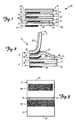
- FIG. 10 a first embodiment of a stack of sheet assemblies according to the present invention, which stack is generally designated by the reference numeral 10.
- the stack 10 includes a multiplicity of sheet assemblies 9, only 2 of which are shown in Figures 1 and 2.
- Each sheet assembly 9 comprises first and second sheets 11 and 12 having the same peripheral shape and size, with each sheet 11 and 12 having front and rear major surfaces and having first and second opposite edges 13, 14 and 15, 16 respectively.
- a first layer 18 of adhesive permanently adheres a portion of the rear surface of the first sheet 11 adjacent its first edge 13 to the front surface of the second sheet 12 adjacent its first edge 15 with the first edges 13 and 15 generally aligned.
- the first layer 18 of adhesive extends a first predetermined distance (e.g., less than half the distance) from the first edges 13, 15 toward the second edges 14, 16 of the sheets 11 and 12.
- a second layer 19 of pressure sensitive adhesive on the rear surface of the second sheet 15 of each sheet assembly 9 comprises (and in this embodiment consists only of) a first portion adhering the rear surface of the second sheet 12 of each sheet assembly 9 to the front surface of the first sheet 11 on the sheet assembly 9 beneath it in the stack 10 within the first distance from the first edges 13 and 15.
- the sheet assemblies 9 also include release means in the form of coatings of low-adhesion backsize 20 on the front surfaces of the first sheets 11 for providing first adhesion zones between the front surfaces of the first sheets 11 and the rear surfaces of the second sheets 12 of the sheet assemblies 9 in the stack 10, the first adhesion zones extending about the first predetermined distance from the first edges 13 and 15 toward the second edges 14 and 16 of the sheets 11 and 12 and providing a release force between the second layers 19 of pressure sensitive adhesive and the front surfaces of the adjacent first sheets 11 in the stack 10 which is lower than the release force of the first layers 18 of adhesive to the first and second sheets 11 and 12 to afford easy initiation of peeling of the uppermost sheet assembly 9 from the adjacent sheet assembly 9 in the stack along the first adhesion zone by pulling on the first sheet 11 of the uppermost sheet assembly 9 on the stack 10.
- the first layers 18 of adhesive that adhere the first sheets 11 to the second sheets 12 are in the shape of a rectangle spaced from the peripheral edges of the sheets 11 and 12 and nearer the center of the sheets 11 and 12 than are the second layers 19 of adhesive which are in the shape of stripe completely across the sheets 11 and 12 adjacent their first edges 13 and 15.
- edges of the second layers 19 of pressure sensitive adhesive adjacent the second edges 14 and 16 of the sheets 11 and 12 are spaced toward the first edges 13 and 15 of the sheets 11 and 12 from the edges of the first layers 18 of pressure sensitive adhesive adjacent the second edges 14 and 16 of the sheets 11 and 12 so that pulling the second edge 14 of the first sheet 11 away from the second edge 16 of the second sheet 12 in the uppermost sheet assembly 9 in the stack as is illustrated in Figure 2 will initiate peeling of the second layer 19 of pressure sensitive adhesive away from the adjacent sheet assembly 9 in the stack 10 as the top sheet assembly 9 is being removed from the stack 10.
- the sheet assemblies 9 can be used for various purposes including carbonless paper notes, form sets, or labels with a receipt portion provided by the first sheet 11, and can have indicia printed on their front surfaces. Such indicia could, for example, include bar codes, or sequential alpha numeric characters.
- the second sheets 12 preferably have a layer 21 of a release coating along their front surfaces which affords release from the layer 18 of adhesive so that the first sheet 11 can be separated from the second sheet 12 after the sheet assembly 9 is separate from the stack 10 and adhered to a substrate by the layer 19 of pressure sensitive adhesive.
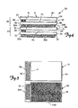
- FIG. 30 a second embodiment of a stack of sheet assemblies according to the present invention, which stack of sheet assemblies is generally designated by the reference numeral 30.
- the stack 30 of sheet assemblies includes a multiplicity of sheet assemblies 29, only 2 of which are shown in Figures 4 and 6.
- Each sheet assembly 29 comprises first and second rectangular sheets 31 and 32 having the same peripheral shape and size, with each sheet 31 and 32 having front and rear major surfaces and having first and second opposite edges 33, 34 and 35, 36 respectively.
- a first layer 38 of adhesive permanently adheres a portion of the rear surface of the first sheet 31 adjacent its first edge 33 to the front surface of the second sheet 32 adjacent its first edge 35 with the first edges 33 and 35 generally aligned.
- the first layer 38 of adhesive extends a first predetermined distance (e.g., less than half the distance) from the first edges 33, 35 toward the second edges 34, 36 of the sheets 31 and 32.
- the first sheets 31 have a transverse line of perforations 41 along the edges of the first layers of adhesive 38 adjacent the second edges 34 of the first sheets 31 so that the portions of the first sheets 31 between the perforations 41 and their second edges 34 are manually removable.
- a second layer 39 of pressure sensitive adhesive on the rear surface of the second sheet 32 of each sheet assembly 29 comprises a first portion 39a within the first distance from the first edges 33 and 35, and a second portion 39b positioned between the first adhesion zone and the second edge 36 of the second sheet 32.
- the portions 39a and 39b of the second layer 39 of pressure sensitive adhesive adhere the rear surface of the second sheet 32 of the sheet assembly 29 to the front surface of the first sheet 31 on the sheet assembly 29 beneath it in the stack 30.
- the sheet assemblies 29 also include release means in the form of coatings of low-adhesion backsize 40 on the front surfaces of the first sheets 31 and the use of less aggressive pressure sensitive adhesive in the portions 39a than in the portions 39b of the second layers of pressure sensitive adhesive 39 for providing (1) first adhesion zones between the front surfaces of the first sheets 31 and the rear surfaces of the second sheets 32 of the sheet assemblies 29 in the stack 30 which extend about the first predetermined distance from the first edges 33 and 35 toward the second edges 34 and 36 of the sheets 31 and 32 and providing a release force between the first portions 39a of second layers 39 of pressure sensitive adhesive and the front surfaces of the adjacent first sheets 31 in the stack 30 which is lower than the release force of the first layers 38 of adhesive to the first and second sheets 31 and 32 to afford easy initiation of peeling of the uppermost sheet assembly 29 from the adjacent sheet assembly 29 in the stack along the first adhesion zone by pulling on the first sheet 31 of the uppermost sheet assembly 29 on the stack 30 as is seen in Figure 6; and for providing (2) a second adhesion zone between the front surfaces of
- the first layers 38 of adhesive that adhere the first sheets 31 to the second sheets 32 are in the shape of a rectangle spaced slightly on three sides from the peripheral edges of the sheets 31 and 32, and the first portions 39a of the second layers 39 of pressure sensitive adhesive are also in the shape of a rectangle having elongate sides aligned in the stack 30 with the elongate sides of the first layers 38 of adhesive, but having opposite ends that are spaced further from the peripheral edges of the sheets 31 and 32 than are opposite ends of the first layers 38 of adhesive.
- the sheet assemblies 29 can be used for various purposes including carbonless paper notes, form sets, or labels with a receipt portion provided by the first sheet 31, and can have indicia printed on their front surfaces.
- the second sheets 32 preferably have a layer 43 of release coating along a portion of their front surfaces which enhance the graphic character of any previously printed indicia.
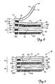
- FIG. 7 there is shown a third embodiment of a stack of sheet assemblies according to the present invention, which stack of sheet assemblies is generally designated by the reference numeral 50.
- the stack 50 of sheet assemblies includes a multiplicity of sheet assemblies 49, only 2 of which are shown in Figure 7.
- Each sheet assembly 49 comprises first and second rectangular sheets 51 and 52 having the same peripheral shape and size, with each sheet 51 and 52 having front and rear major surfaces and having first and second opposite edges 53, 54 and 55, 56 respectively.
- a first layer 58 of adhesive permanently adheres a portion of the rear surface of the first sheet 51 adjacent its first edge 53 to the front surface of the second sheet 52 adjacent its first edge 55 with the first edges 53 and 55 generally aligned.
- the first layer 58 of adhesive extends a first predetermined distance (e.g., less than half the distance) from the first edges 53, 55 toward the second edges 54, 56 of the sheets 51 and 52.
- the first sheets 51 have a transverse line of perforations 61 along the edges of the first layers of adhesive 58 adjacent the second edges 54 of the first sheets 51 so that the portions of the first sheets 51 between the perforations 61 and their second edges 54 are manually removable.
- a second layer 59 of pressure sensitive adhesive on the rear surface of the second sheet 55 of each sheet assembly 49 comprises a first portion 59a within the first distance from the first edges 53 and 55, and a second portion 59b positioned between the first adhesion zone and the second edge 56 of the second sheet 52.
- the portions 59a and 59b of the second layer 59 of pressure sensitive adhesive adhere the rear surface of the second sheet 52 of the sheet assembly 49 to the front surface of the first sheet 51 on the sheet assembly 49 beneath it in the stack 50.
- the sheet assemblies 49 also include release means in the form of coatings of low-adhesion backsize 60 on the front surfaces of the first sheets 51 and the use of discontinuous portions 59a consisting of triangular shaped parts with apexes adjacent the first edges 53 and 54 of the sheets and continuous portions 59b of the second layers of pressure sensitive adhesive 59 for providing (1) first adhesion zones between the front surfaces of the first sheets 51 and the rear surfaces of the second sheets 52 of the sheet assemblies 49 in the stack 50 which extend about the first predetermined distance from the first edges 53 and 55 toward the second edges 54 and 56 of the sheets 51 and 52 and providing a release force between the first portions 59a of second layers 59 of pressure sensitive adhesive and the front surfaces of the adjacent first sheets 51 in the stack 50 which is lower than the release force of the first layers 58 of adhesive to the first and second sheets 51 and 52 to afford easy initiation of peeling of the uppermost sheet assembly 49 from the adjacent sheet assembly 49 in the stack along the first adhesion zone by pulling on the first sheet 51 of the uppermost sheet assembly 49 on the
- the first layers 58 of adhesive that adhere the first sheets 51 to the second sheets 52 are in the shape of rectangles spaced slightly on three sides from the peripheral edges of the sheets 51 and 52. Pulling the second edge 54 of the first sheet 51 away from the second edge 56 of the second sheet 52 in the uppermost sheet assembly 49 in the stack will fairly easily separate the bond between the first portion 59a of the second layer of pressure sensitive adhesive 59, and will thereby initiate peeling of the more aggressive second portion 59b of the second layer 59 of pressure sensitive adhesive away from the adjacent sheet assembly 49 in the stack 50 as the top sheet assembly 49 is being removed from the stack 50.
- the sheet assemblies 49 can be used for the same purposes as the sheet assemblies 29, and can have indicia printed on their front surfaces.
- the second sheets 52 preferably have a layer 63 of release coating along a portion of their front surfaces which enhance the graphic character of any previously printed indicia.
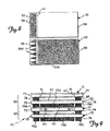
- FIG. 10 there is shown a fourth embodiment of a stack of sheet assemblies according to the present invention, which stack of sheet assemblies is generally designated by the reference numeral 70.
- the stack 70 of sheet assemblies includes a multiplicity of sheet assemblies 69, only 2 of which are shown in Figure 9.
- Each sheet assembly 69 comprises first and second rectangular sheets 71 and 72 having the same peripheral shape and size, with each sheet 71 and 72 having front and rear major surfaces and having first and second opposite edges 73, 74 and 75, 76 respectively.
- a first layer 78 of adhesive permanently adheres a portion of the rear surface of the first sheet 71 adjacent its first edge 73 to the front surface of the second sheet 72 adjacent its first edge 75 with the first edges 73 and 75 generally aligned
- a third layer 98 of adhesive permanently adheres a portion of the rear surface of the first sheet 71 adjacent its second edge 74 to the front surface of the second sheet 72 adjacent its second edge 76 with the first and second edges 73, 75 and 74, 76 generally aligned.
- the first and third layers 78 and 98 of adhesive extend a first predetermined distance (e.g., less than one third the distance) from the edges 73, 74, 75 and 76 which they are adjacent toward the opposite edges edges 73, 74, 75, and 76 of the sheets 71 and 72.
- the first sheets 71 have spaced transverse lines of perforations 81 along the adjacent edges of the first and third layers 78 and 98 of adhesive 78 so that the portions of the first sheets 71 between the perforations 41 are manually removable.
- a second layer 79 of pressure sensitive adhesive on the rear surface of the second sheet 72 of each sheet assembly 69 comprises a first portion 79a within the first distance from the first edges 73 and 75, a third portion 79c within the first distance from the second edges 74 and 76, and a second central portion 79b positioned between the first and third portions 79a and 79c.
- the portions 79a, 79b and 79c of the second layer 79 of pressure sensitive adhesive adhere the rear surface of the second sheet 72 of the sheet assembly 69 to the front surface of the first sheet 71 on the sheet assembly 69 beneath it in the stack 70.
- the sheet assemblies 69 also include release means in the form of coatings of low-adhesion backsize 40 on the front surfaces of the first sheets 71 and the use of less of the same adhesive or less aggressive pressure sensitive adhesive in the portions 79a and 79c than in the portions 79b of the second layers of pressure sensitive adhesive 79 for providing (1) first adhesion zones between the front surfaces of the first sheets 71 and the rear surfaces of the second sheets 72 of the sheet assemblies 69 in the stack 70 which extend about the first predetermined distance from the edges 73, 74, 75 and 76 of the sheets 71 and 72 and provide a release force between the first and third portions 79a and 79c of the second layers 79 of pressure sensitive adhesive and the front surfaces of the adjacent first sheets 71 in the stack 70 which is lower than the release force of the first layers 78 of adhesive to the first and second sheets 71 and 72 to afford easy initiation of peeling of the uppermost sheet assembly 69 from the adjacent sheet assembly 69 in the stack along the first and third adhesion zone by pulling on the first sheet 71
- the first and third layers 78 and 98 of adhesive that adhere the first sheets 71 to the second sheets 72 are in the shape of a rectangles spaced slightly on three sides from the peripheral edges of the sheets 71 and 72, and the first and third portions 79a and 79c of the second layers 79 of pressure sensitive adhesive are also in the shape of rectangles having elongate sides aligned in the stack 70 with the elongate sides of the first and third layers 78 and 98 of adhesive, respectively, but having opposite ends that are spaced further from the peripheral edges of the sheets 71 and 72 than are opposite ends of the first and third layers 78 and 98 of adhesive.
- the sheet assemblies 69 can be used for various purposes including carbonless paper notes, form sets, or labels with a receipt portion provided by the first sheet 71, and can have indicia printed on their front surfaces.
- the second sheets 72 preferably have a layer 83 of release coating along a portion of their front surfaces which enhance the graphic character of any previously printed indicia.
- FIGs 11 through 13 illustrate a container 100 from which sheet assemblies 29 or 49 from the stacks 30 or 50 of sheet assemblies can be dispensed, which container is illustrated in combination with the stack 30 of sheet assemblies 29 illustrated in Figures 4, 5 and 6.
- the container 100 comprises walls around the stack of sheet assemblies, including a bottom wall 102 supporting the stack 30 of sheet assemblies 29, side walls along and closely spaced from the edges of the sheets 31 and 32 in the stack of sheet assemblies 29 including a first end wall 106 along the first edges 33 and 35 of the sheets 31 and 32 in the stack 30 of sheet assemblies 29, and a top wall 109 along the top of the stack 30 of sheet assemblies 29.
- the top wall 109 has an edge surface 110 spaced from the first end wall 106 to provide an opening 112 therebetween, which edge surface 110 is spaced from the end wall 106 by a distance greater than said first predetermined distance that the layer 38 of adhesive extends so that with an end portion of the first sheet 31 adjacent its second edge 34 of the uppermost sheet assembly 29 in the stack 29 projecting through the opening 112, tension applied manually to that end portion will first cause separation of first portion 39a of the second layer of pressure sensitive adhesive 39 on the second sheet 32 of the uppermost sheet assembly 29 in the stack 30 from the second sheet assembly 29 in the stack 29 along the first adhesion zone by bending that second sheet 32 around the edge surface 110 ( Figure 12), whereafter the second sheet 32 of the uppermost sheet assembly 29 in the stack 30 will be pulled along the inner surface of the top wall 109 and around the edge surface 110 while carrying with it the first sheet 31 of the second sheet assembly 29 in the stack 30 ( Figure 12) until the end portion of the second sheet 32 of the uppermost sheet assembly 29 in the stack 30 carries the first sheet 31 of the
- a stack of sheet assemblies of the embodiment illustrated in Figures 1, 2, and 3 were produced by first preparing a plurality of the first and second sheets 11 and 12, then laminating them together to form the sheet assemblies 9, and then stacking the sheet assemblies 9.
- the first sheet 11 was prepared by apsheeting an 12.7 mm strip of a 0.13 mm thick tackified acrylic transfer tape (available from 3M as Scotch TM brand #969 Adhesive Transfer Tape) 3.2 mm from the 118 mm edge on the face without a release coating of the liner Daubert 4020 (commercially available from Daubert Coated Products Company) forming an 118 mm wide and 81 mm long sheet.
- the second sheet 12 was prepared on a separate paper of the same size.
- the paper was printed and coated with the silicone release system of 96 parts Syl-Off R 7610 and 4 parts Syl-Off R 7611 (commercially available from Dow Corning Corporation) and cured. To the opposite side was coated an 12.7 mm strip of .03 mm thick adhesive Duro-tak R 34-4142 (commercially available from National Starch and Chemical Corporation) 4.8 mm from the 118 mm wide edge.
- the sheet assemblies 9 were found to be easily separated from the stack 10 by merely grasping the first sheet 11 of the uppermost sheet assembly 9 and lifting. As described previously, when the first sheet 11 of the uppermost sheet assembly 9 was at the top of the stack 10, the uppermost sheet assembly 9 was dispensed while peeling parallel to the 81 mm edge of the stack 10.
- the then uppermost sheet assembly 9 sheet was dispensed while peeling parallel to the 118 mm edge.
- the adhesive coating 18 on the removed sheet assembly 9 was adhered to a substrate, the first sheet 11 could be easily removed from the second sheet 12 and adhered to another substrate by the first layer of adhesive 18.
- a stack of labels generally of the form shown in Figure Nos. 9 and 10 were produced by printing paper and then coating it with the silicone release system of 96 parts Syl-Off R 7610 and 4 parts Syl-Off R 7611 and curing the release material.
- To the opposite side of the top sheet were coated 12.7 mm strips of 0.03 mm thick adhesive Duro-tak R 34-4142.
- the adhesive bars on the top sheet were approximately 9.5 mm wide and 67.0 mm long on the 82.5 mm long and 127.0 mm wide sheet.
- the bottom sheet was printed and coated with the same release material, as the pictured sheet 22. The same adhesive was used to provide bars 9.5 mm wide and 65.0 mm long.
- the central block of adhesive 66 mm long and 87 mm wide was also applied in the center of the sheet.
- the sheets were laminated, stacked and trimmed. The sheets easily dispensed and were applied to various surfaces.
- the top sheet was permanently bonded to the bottom using the top sheet's adhesive. The sheets bonded to surfaces, and the central section of the top sheet was easily detached along the lines of weakness formed by a perforation.
- a stack of label or sheet assemblies of the embodiment illustrated in Figures 4, 5, and 6 were produced using the paper, release material, and adhesive described in Example No. 2.
- the first sheet 31 was prepared as above, except only a single layer or bar 38 of adhesive was applied, and only a single corresponding line of weakness was provided by perforations 41.
- the second sheet 32 was prepared as in Example 2 above, except only a single bar or layer portion 39a of adhesive was provided, and the second portion 39b of the layer 39 of pressure sensitive adhesive was extended to be 98 mm wide.
- the sheets were laminated to form the sheet assemblies 29, stacked and trimmed.
- the sheets assemblies 29 easily dispensed from the stack 30 and were applied to various surfaces.
- the first sheet 31 was permanently bonded to the second sheet 32 by the layer 38 of adhesive. After a dispensed sheet assembly was adhered to a surface by the layer of pressure sensitive adhesive 39, the portion of the first sheet 31 between the perforations 41 and its edge 34 was easily detached along the perforations 41.
- a stack of label or sheet assemblies 49 generally of the embodiment shown in Figures 7 and 8 were produced as in Example No. 3, except that the pattern of the first portion 59a of the layer 39 of pressure sensitive adhesive was changed. That pattern was made as series of six isosceles triangles with an 8 mm base and 12 mm sides, spaced 4 mm between bases.
- the sheet assemblies 50 easily dispensed and were applied to various surfaces.
- the first sheet 51 was permanently bonded to the second sheet 52 by the layer 58 of adhesive.
- the first sheet 51 was permanently bonded to the second sheet 52 by the layer 58 of adhesive.
- a container or dispenser for label or sheet assemblies generally of the embodiment shown in Figure 11 was made for a stack 50 of label or sheet assemblies 49 of the embodiment described in Example No. 4.
- the dispenser or container 100 was formed from a 0.51 mm card stock material.
- the stack 50 was 117 mm long and 77 mm wide, the side walls of the dispenser 100 were 22 mm high, the base or bottom wall 102 was 86 mm wide and 122 mm long, and the top wall 109 was 86 mm wide and 92 mm long, leaving an exit orifice or opening 112 82 mm wide and 33 mm long.
- the layer of pressure sensitive adhesive 59 on the second sheet 52 adjacent the bottom wall 102 was adhered thereto, and the first sheet 51 of the sheet assembly 49 adjacent the top wall 109 was positioned so that it projected through the opening 112. Sheet assemblies 49 were easily dispensed from the dispenser 100 and used in the manner described above.
- the dispenser 100 could be used in horizontal, vertical, or other attitudes.
- each sheet assembly could contain more than two sheets adhered together in the manners that the first sheets are adhered to the second sheets in the above embodiments.
- the scope of the present invention should not be limited to the structures described in this application, but only by structures described by the language of the claims and the equivalents of those structures.
Landscapes
- Engineering & Computer Science (AREA)
- Physics & Mathematics (AREA)
- Theoretical Computer Science (AREA)
- Mathematical Physics (AREA)
- Business, Economics & Management (AREA)
- Educational Administration (AREA)
- Educational Technology (AREA)
- General Physics & Mathematics (AREA)
- Adhesive Tapes (AREA)
- Laminated Bodies (AREA)
Abstract
Description
- The present invention relates to stacks of sheet assemblies, each of which sheet assemblies comprises at least two sheets adhered together along at least one edge, the stacks being so constructed that individual sheet assemblies may be removed from the stack.
- The present invention provides a stack of sheet assemblies that are easily removed from the stack and applied to a substrate, and require no liner or use of sheets of different sizes in the stack to afford such removal.
- According to the present invention there is provided a stack of sheet assemblies, each of which sheet assemblies comprises first and second sheets each having front and rear major surfaces and first and second opposite edges, a first layer of adhesive adhering a portion of the rear surface of the first sheet adjacent the first edge of the first sheet to the front surface of the second sheet adjacent the first edge of the second sheet with the first edges generally aligned, the first layer of adhesive extending a first predetermined distance from the first edges toward the second edges of the sheets, and a second layer of pressure sensitive adhesive on the rear surface of the second sheet. The second layer of pressure sensitive adhesive comprises a first portion adhering the rear surface of the second sheet of the sheet assembly to the front surface of the first sheet on the sheet assembly beneath it in the stack within the first distance from the first edge. The sheet assemblies also include release means for providing first adhesion zones between the front surfaces of the first sheets and the rear surfaces of the second sheets of the sheet assemblies in the stack, the first adhesion zones extending about the first predetermined distance from the first edges toward the second edges of the sheets and providing a release force between the first portions of the second layers of adhesive and the front surfaces of the adjacent first sheets in the stack which is lower than the release force of the first layers of adhesive to the first and second sheets to afford easy initiation of peeling of the uppermost sheet assembly from the adjacent sheet assembly in the stack along the first adhesion zone by pulling on the first sheet of the uppermost sheet assembly on the stack.
- In a first embodiment of the stack of sheet assemblies the edges of the second layers of pressure sensitive adhesive adjacent the second edges of the sheets are spaced toward the first edges of the sheets from the edges of the first layers of pressure sensitive adhesive adjacent the second edges of the sheets so that movement of the second edge of the first sheet of the uppermost sheet assembly in the stack away from the second edge of the second sheet of that uppermost sheet assembly will initiate peeling of its second layer of pressure sensitive adhesive away from the adjacent sheet assembly in the stack.
- In a second embodiment of the stack of sheet assemblies the second layers of pressure sensitive adhesive adhering the rear surfaces of the second sheets of the sheet assemblies to the front surfaces of the first sheets on the sheet assemblies beneath them in the stack include second portions positioned between the first adhesion zones and the second edges of the second sheets, and the release means provides second adhesion zones between the front surfaces of the first sheets and the rear surfaces of the second sheets in the stack adjacent the second portions with the second adhesion zones having release forces higher than the low release forces in the first adhesion zones that are sufficiently high to firmly adhere adjacent sheet assemblies in the stack together while affording continued peeling away of the uppermost sheet assembly in the stack along its second adhesion zone after initiating of such peeling along its first adhesion zone.
- This second embodiment of the stack of sheet assemblies can be easily dispensed from a container comprising walls around the stack of sheet assemblies, including a bottom wall supporting the stack of sheet assemblies, side walls along and closely spaced from the edges of the sheets in the stack of sheet assemblies including a first end wall along the first edges of the sheets in the stack of sheet assemblies, and a top wall along the top of the stack of sheets, the top wall having an edge surface spaced from the first end wall to provide an opening therebetween. The edge surface of the top wall is spaced from the end wall by a distance greater than the first predetermined distance so that with an end portion of the first sheet adjacent its second edge of the uppermost sheet assembly in the stack projecting through the opening, tension applied manually to that end portion will first cause separation of the second sheet of the uppermost sheet assembly in the stack from the second sheet assembly in the stack along the first adhesion zone by bending that second sheet around the edge surface, whereafter the second sheet of the uppermost sheet assembly in the stack will be pulled along the inner surface of the top wall of the container and around the edge surface while arching and carrying with it the first sheet of the second sheet assembly in the stack until an end portion of the second sheet of the uppermost sheet carries an end portion of the first sheet of the second sheet assembly through the opening and is subsequently peeled therefrom, leaving the first sheet of that second sheet assembly (now the uppermost sheet assembly in the stack) projecting through the opening in a position to also be manually pulled therethrough in the manner just described for the uppermost sheet assembly in the stack.
- In yet a third embodiment of the stack of sheet assemblies the sheet assemblies each include a third layer of adhesive adhering a portion of the rear surface of the first sheet adjacent the second edge of the first sheet to the front surface of the rear sheet adjacent the second edge of the second sheet with the second edges generally aligned, the third layer of adhesive extending a distance about equal to the first predetermined distance from the second edges toward the first edges of the sheets, and the first sheets are transversely perforated along both adjacent edges of the first and third layers of adhesive.
- The present invention will be further described with reference to the accompanying drawing wherein like reference numerals refer to like parts in the several views, and wherein:
- Figure 1 is a much enlarged side view of a first embodiment of a stack of sheet assemblies according to the present invention;
- Figure 2 illustrates initiating separation between the two sheet assemblies in the stack of sheet assemblies illustrated in Figure 1;
- Figure 3 illustrates the two sheets of one of the sheet assemblies in the stack of sheet assemblies illustrated in Figure 1, which sheets are shown separated from each other to show the patterns of adhesives on the sheets;
- Figure 4 is a much enlarged side view of a second embodiment of a stack of sheet assemblies according to the present invention;
- Figure 5 illustrates the two sheets of one of the sheet assemblies in the stack of sheet assemblies illustrated in Figure 4, which sheets are shown separated from each other to show the patterns of adhesives on the sheets;
- Figure 6 illustrates initiating separation between the two sheet assemblies in the stack of sheet assemblies illustrated in Figure 4;
- Figure 7 is a much enlarged side view of a third embodiment of a stack of sheet assemblies according to the present invention;
- Figure 8 illustrates the two sheets of one of the sheet assemblies in the stack of sheet assemblies illustrated in Figure 7, which sheets are shown separated from each other to show the patterns of adhesives on the sheets;
- Figure 9 is a much enlarged side view of a forth embodiment of a stack of sheet assemblies according to the present invention;
- Figure 10 illustrates the two sheets of one of the sheet assemblies in the stack of sheet assemblies illustrated in Figure 9, which sheets are shown separated from each other to show the patterns of adhesives on the sheets;
- Figure 11 illustrates a container from which the sheet assemblies from the second and third embodiments of the stack of sheet assemblies may be dispensed, which container has a part broken away to show details; and
- Figures 12 and 13 illustrate sequential positions of sheet assemblies during dispensing of sheet assemblies from the container of Figure 11.
- Referring now to Figures 1, 2, and 3 of the drawing, there is shown a first embodiment of a stack of sheet assemblies according to the present invention, which stack is generally designated by the
reference numeral 10. - The
stack 10 includes a multiplicity ofsheet assemblies 9, only 2 of which are shown in Figures 1 and 2. Eachsheet assembly 9 comprises first andsecond sheets sheet opposite edges first layer 18 of adhesive permanently adheres a portion of the rear surface of thefirst sheet 11 adjacent itsfirst edge 13 to the front surface of thesecond sheet 12 adjacent itsfirst edge 15 with thefirst edges first layer 18 of adhesive extends a first predetermined distance (e.g., less than half the distance) from thefirst edges second edges sheets second layer 19 of pressure sensitive adhesive on the rear surface of thesecond sheet 15 of eachsheet assembly 9 comprises (and in this embodiment consists only of) a first portion adhering the rear surface of thesecond sheet 12 of eachsheet assembly 9 to the front surface of thefirst sheet 11 on thesheet assembly 9 beneath it in thestack 10 within the first distance from thefirst edges sheet assemblies 9 also include release means in the form of coatings of low-adhesion backsize 20 on the front surfaces of thefirst sheets 11 for providing first adhesion zones between the front surfaces of thefirst sheets 11 and the rear surfaces of thesecond sheets 12 of the sheet assemblies 9 in thestack 10, the first adhesion zones extending about the first predetermined distance from thefirst edges second edges sheets second layers 19 of pressure sensitive adhesive and the front surfaces of the adjacentfirst sheets 11 in thestack 10 which is lower than the release force of thefirst layers 18 of adhesive to the first andsecond sheets uppermost sheet assembly 9 from theadjacent sheet assembly 9 in the stack along the first adhesion zone by pulling on thefirst sheet 11 of theuppermost sheet assembly 9 on thestack 10. As can be seen in Figure 3, thefirst layers 18 of adhesive that adhere thefirst sheets 11 to thesecond sheets 12 are in the shape of a rectangle spaced from the peripheral edges of thesheets sheets second layers 19 of adhesive which are in the shape of stripe completely across thesheets first edges second layers 19 of pressure sensitive adhesive adjacent thesecond edges sheets first edges sheets first layers 18 of pressure sensitive adhesive adjacent thesecond edges sheets second edge 14 of thefirst sheet 11 away from thesecond edge 16 of thesecond sheet 12 in theuppermost sheet assembly 9 in the stack as is illustrated in Figure 2 will initiate peeling of thesecond layer 19 of pressure sensitive adhesive away from theadjacent sheet assembly 9 in thestack 10 as thetop sheet assembly 9 is being removed from thestack 10. Similarly, though not shown, similar removal of asheet assembly 9 will occur when thesecond sheet 12 is uppermost in thestack 10, and thesecond sheet 12 is pulled away from thefirst sheet 11 in a direction parallel to the longitudinal edges of thesheets sheet assemblies 9 can be used for various purposes including carbonless paper notes, form sets, or labels with a receipt portion provided by thefirst sheet 11, and can have indicia printed on their front surfaces. Such indicia could, for example, include bar codes, or sequential alpha numeric characters. Also, thesecond sheets 12 preferably have alayer 21 of a release coating along their front surfaces which affords release from thelayer 18 of adhesive so that thefirst sheet 11 can be separated from thesecond sheet 12 after thesheet assembly 9 is separate from thestack 10 and adhered to a substrate by thelayer 19 of pressure sensitive adhesive. - Referring now to Figures 4, 5 and 6 of the drawing, there is shown a second embodiment of a stack of sheet assemblies according to the present invention, which stack of sheet assemblies is generally designated by the
reference numeral 30. - The
stack 30 of sheet assemblies includes a multiplicity ofsheet assemblies 29, only 2 of which are shown in Figures 4 and 6. Eachsheet assembly 29 comprises first and secondrectangular sheets sheet opposite edges first layer 38 of adhesive permanently adheres a portion of the rear surface of thefirst sheet 31 adjacent itsfirst edge 33 to the front surface of thesecond sheet 32 adjacent itsfirst edge 35 with thefirst edges first layer 38 of adhesive extends a first predetermined distance (e.g., less than half the distance) from thefirst edges second edges sheets first sheets 31 have a transverse line ofperforations 41 along the edges of the first layers ofadhesive 38 adjacent thesecond edges 34 of thefirst sheets 31 so that the portions of thefirst sheets 31 between theperforations 41 and theirsecond edges 34 are manually removable. A second layer 39 of pressure sensitive adhesive on the rear surface of thesecond sheet 32 of eachsheet assembly 29 comprises a first portion 39a within the first distance from thefirst edges second edge 36 of thesecond sheet 32. The portions 39a and 39b of the second layer 39 of pressure sensitive adhesive adhere the rear surface of thesecond sheet 32 of thesheet assembly 29 to the front surface of thefirst sheet 31 on thesheet assembly 29 beneath it in thestack 30. Thesheet assemblies 29 also include release means in the form of coatings of low-adhesion backsize 40 on the front surfaces of thefirst sheets 31 and the use of less aggressive pressure sensitive adhesive in the portions 39a than in the portions 39b of the second layers of pressure sensitive adhesive 39 for providing (1) first adhesion zones between the front surfaces of thefirst sheets 31 and the rear surfaces of thesecond sheets 32 of the sheet assemblies 29 in thestack 30 which extend about the first predetermined distance from thefirst edges second edges sheets first sheets 31 in thestack 30 which is lower than the release force of thefirst layers 38 of adhesive to the first andsecond sheets uppermost sheet assembly 29 from theadjacent sheet assembly 29 in the stack along the first adhesion zone by pulling on thefirst sheet 31 of theuppermost sheet assembly 29 on thestack 30 as is seen in Figure 6; and for providing (2) a second adhesion zone between the front surfaces of thefirst sheets 31 and the rear surfaces of thesecond sheets 32 in the stack adjacent the second portion 39b with the second adhesion zone having a release force higher than the low release force in the first adhesion zone that is sufficiently high to firmly adhereadjacent sheet assemblies 29 in the stack together while affording continued peeling away of theuppermost sheet assembly 29 in thestack 30 along the second adhesion zone after initiating of such peeling along the first adhesion zone. As can be seen in Figure 5, thefirst layers 38 of adhesive that adhere thefirst sheets 31 to thesecond sheets 32 are in the shape of a rectangle spaced slightly on three sides from the peripheral edges of thesheets stack 30 with the elongate sides of thefirst layers 38 of adhesive, but having opposite ends that are spaced further from the peripheral edges of thesheets first layers 38 of adhesive. Pulling thesecond edge 34 of thefirst sheet 31 away from thesecond edge 36 of thesecond sheet 32 in theuppermost sheet assembly 29 in the stack as is illustrated in Figure 6 will fairly easily separate the bond between the first portion 39a of the second layer of pressure sensitive adhesive 39, and will thereby initiate peeling of the more aggressive second portion 39b of the second layer 39 of pressure sensitive adhesive away from theadjacent sheet assembly 29 in thestack 30 as thetop sheet assembly 29 is being removed from thestack 30. Thesheet assemblies 29 can be used for various purposes including carbonless paper notes, form sets, or labels with a receipt portion provided by thefirst sheet 31, and can have indicia printed on their front surfaces. Also, thesecond sheets 32 preferably have alayer 43 of release coating along a portion of their front surfaces which enhance the graphic character of any previously printed indicia. - Referring now to Figures 7 and 8 of the drawing, there is shown a third embodiment of a stack of sheet assemblies according to the present invention, which stack of sheet assemblies is generally designated by the
reference numeral 50. - The
stack 50 of sheet assemblies includes a multiplicity ofsheet assemblies 49, only 2 of which are shown in Figure 7. Eachsheet assembly 49 comprises first and secondrectangular sheets sheet opposite edges first layer 58 of adhesive permanently adheres a portion of the rear surface of thefirst sheet 51 adjacent itsfirst edge 53 to the front surface of thesecond sheet 52 adjacent itsfirst edge 55 with thefirst edges first layer 58 of adhesive extends a first predetermined distance (e.g., less than half the distance) from thefirst edges second edges sheets first sheets 51 have a transverse line ofperforations 61 along the edges of the first layers ofadhesive 58 adjacent thesecond edges 54 of thefirst sheets 51 so that the portions of thefirst sheets 51 between theperforations 61 and theirsecond edges 54 are manually removable. A second layer 59 of pressure sensitive adhesive on the rear surface of thesecond sheet 55 of eachsheet assembly 49 comprises a first portion 59a within the first distance from thefirst edges second edge 56 of thesecond sheet 52. The portions 59a and 59b of the second layer 59 of pressure sensitive adhesive adhere the rear surface of thesecond sheet 52 of thesheet assembly 49 to the front surface of thefirst sheet 51 on thesheet assembly 49 beneath it in thestack 50. Thesheet assemblies 49 also include release means in the form of coatings of low-adhesion backsize 60 on the front surfaces of thefirst sheets 51 and the use of discontinuous portions 59a consisting of triangular shaped parts with apexes adjacent thefirst edges first sheets 51 and the rear surfaces of thesecond sheets 52 of the sheet assemblies 49 in thestack 50 which extend about the first predetermined distance from thefirst edges second edges sheets first sheets 51 in thestack 50 which is lower than the release force of thefirst layers 58 of adhesive to the first andsecond sheets uppermost sheet assembly 49 from theadjacent sheet assembly 49 in the stack along the first adhesion zone by pulling on thefirst sheet 51 of theuppermost sheet assembly 49 on thestack 50 as is seen in Figure 6; and for providing (2) a second adhesion zone between the front surfaces of thefirst sheets 51 and the rear surfaces of thesecond sheets 52 in the stack adjacent the second portion 59b with the second adhesion zone having a release force higher than the low release force in the first adhesion zone that is sufficiently high to firmly adhereadjacent sheet assemblies 49 in the stack together while affording continued peeling away of theuppermost sheet assembly 49 in thestack 50 along the second adhesion zone after initiating of such peeling along the first adhesion zone. As can be seen in Figure 5, thefirst layers 58 of adhesive that adhere thefirst sheets 51 to thesecond sheets 52 are in the shape of rectangles spaced slightly on three sides from the peripheral edges of thesheets second edge 54 of thefirst sheet 51 away from thesecond edge 56 of thesecond sheet 52 in theuppermost sheet assembly 49 in the stack will fairly easily separate the bond between the first portion 59a of the second layer of pressure sensitive adhesive 59, and will thereby initiate peeling of the more aggressive second portion 59b of the second layer 59 of pressure sensitive adhesive away from theadjacent sheet assembly 49 in thestack 50 as thetop sheet assembly 49 is being removed from thestack 50. Thesheet assemblies 49 can be used for the same purposes as the sheet assemblies 29, and can have indicia printed on their front surfaces. Also, thesecond sheets 52 preferably have alayer 63 of release coating along a portion of their front surfaces which enhance the graphic character of any previously printed indicia. - Referring now to Figures 9 and 10 of the drawing, there is shown a fourth embodiment of a stack of sheet assemblies according to the present invention, which stack of sheet assemblies is generally designated by the
reference numeral 70. - The
stack 70 of sheet assemblies includes a multiplicity ofsheet assemblies 69, only 2 of which are shown in Figure 9. Eachsheet assembly 69 comprises first and secondrectangular sheets sheet opposite edges first sheet 71 adjacent itsfirst edge 73 to the front surface of thesecond sheet 72 adjacent itsfirst edge 75 with thefirst edges third layer 98 of adhesive permanently adheres a portion of the rear surface of thefirst sheet 71 adjacent itssecond edge 74 to the front surface of thesecond sheet 72 adjacent itssecond edge 76 with the first andsecond edges third layers 78 and 98 of adhesive extend a first predetermined distance (e.g., less than one third the distance) from theedges sheets first sheets 71 have spaced transverse lines ofperforations 81 along the adjacent edges of the first andthird layers 78 and 98 of adhesive 78 so that the portions of thefirst sheets 71 between theperforations 41 are manually removable. A second layer 79 of pressure sensitive adhesive on the rear surface of thesecond sheet 72 of eachsheet assembly 69 comprises a first portion 79a within the first distance from thefirst edges second edges second sheet 72 of thesheet assembly 69 to the front surface of thefirst sheet 71 on thesheet assembly 69 beneath it in thestack 70. The sheet assemblies 69 also include release means in the form of coatings of low-adhesion backsize 40 on the front surfaces of the first sheets 71 and the use of less of the same adhesive or less aggressive pressure sensitive adhesive in the portions 79a and 79c than in the portions 79b of the second layers of pressure sensitive adhesive 79 for providing (1) first adhesion zones between the front surfaces of the first sheets 71 and the rear surfaces of the second sheets 72 of the sheet assemblies 69 in the stack 70 which extend about the first predetermined distance from the edges 73, 74, 75 and 76 of the sheets 71 and 72 and provide a release force between the first and third portions 79a and 79c of the second layers 79 of pressure sensitive adhesive and the front surfaces of the adjacent first sheets 71 in the stack 70 which is lower than the release force of the first layers 78 of adhesive to the first and second sheets 71 and 72 to afford easy initiation of peeling of the uppermost sheet assembly 69 from the adjacent sheet assembly 69 in the stack along the first and third adhesion zone by pulling on the first sheet 71 of the uppermost sheet assembly 69 on the stack 70; and for providing (2) a second central adhesion zone between the front surfaces of the first sheets 71 and the rear surfaces of the second sheets 72 in the stack adjacent the second portion 79b with the second adhesion zone having a release force higher than the low release force in the first and third adhesion zones that is sufficiently high to firmly adhere adjacent sheet assemblies 69 in the stack together while affording continued peeling away of the uppermost sheet assembly 69 in the stack 70 along the second adhesion zone after initiating of such peeling along the first adhesion zones. As can be seen in Figure 9, the first andthird layers 78 and 98 of adhesive that adhere thefirst sheets 71 to thesecond sheets 72 are in the shape of a rectangles spaced slightly on three sides from the peripheral edges of thesheets stack 70 with the elongate sides of the first andthird layers 78 and 98 of adhesive, respectively, but having opposite ends that are spaced further from the peripheral edges of thesheets third layers 78 and 98 of adhesive. Pulling either of theedges second sheets second sheet assembly 69 in thestack 70 will fairly easily separate the bond between the first or third portions 79a or 79c of the second layer of pressure sensitive adhesive 79, and will thereby initiate peeling of the more aggressive second portion 79b of the second layer 79 of pressure sensitive adhesive away from theadjacent sheet assembly 69 in thestack 70 as thetop sheet assembly 69 is being removed from thestack 70. Thesheet assemblies 69 can be used for various purposes including carbonless paper notes, form sets, or labels with a receipt portion provided by thefirst sheet 71, and can have indicia printed on their front surfaces. Also, thesecond sheets 72 preferably have alayer 83 of release coating along a portion of their front surfaces which enhance the graphic character of any previously printed indicia. - Figures 11 through 13 illustrate a
container 100 from whichsheet assemblies stacks stack 30 ofsheet assemblies 29 illustrated in Figures 4, 5 and 6. Thecontainer 100 comprises walls around the stack of sheet assemblies, including abottom wall 102 supporting thestack 30 ofsheet assemblies 29, side walls along and closely spaced from the edges of thesheets sheet assemblies 29 including afirst end wall 106 along thefirst edges sheets stack 30 ofsheet assemblies 29, and atop wall 109 along the top of thestack 30 ofsheet assemblies 29. The top wall 109 has an edge surface 110 spaced from the first end wall 106 to provide an opening 112 therebetween, which edge surface 110 is spaced from the end wall 106 by a distance greater than said first predetermined distance that the layer 38 of adhesive extends so that with an end portion of the first sheet 31 adjacent its second edge 34 of the uppermost sheet assembly 29 in the stack 29 projecting through the opening 112, tension applied manually to that end portion will first cause separation of first portion 39a of the second layer of pressure sensitive adhesive 39 on the second sheet 32 of the uppermost sheet assembly 29 in the stack 30 from the second sheet assembly 29 in the stack 29 along the first adhesion zone by bending that second sheet 32 around the edge surface 110 (Figure 12), whereafter the second sheet 32 of the uppermost sheet assembly 29 in the stack 30 will be pulled along the inner surface of the top wall 109 and around the edge surface 110 while carrying with it the first sheet 31 of the second sheet assembly 29 in the stack 30 (Figure 12) until the end portion of the second sheet 32 of the uppermost sheet assembly 29 in the stack 30 carries the first sheet 31 of the second sheet assembly 29 in the stack 30 through the opening 112 and is subsequently peeled therefrom, leaving the first sheet 31 of what was originally the second sheet assembly 29 in the stack 30 projecting through the opening 112 in a position to also be manually pulled therethrough in the manner described above. - The present invention will be further described with reference to the following non limiting examples.
- A stack of sheet assemblies of the embodiment illustrated in Figures 1, 2, and 3 were produced by first preparing a plurality of the first and
second sheets sheet assemblies 9, and then stacking thesheet assemblies 9. Thefirst sheet 11 was prepared by apsheeting an 12.7 mm strip of a 0.13 mm thick tackified acrylic transfer tape (available from 3M as Scotch TM brand #969 Adhesive Transfer Tape) 3.2 mm from the 118 mm edge on the face without a release coating of the liner Daubert 4020 (commercially available from Daubert Coated Products Company) forming an 118 mm wide and 81 mm long sheet. Thesecond sheet 12 was prepared on a separate paper of the same size. The paper was printed and coated with the silicone release system of 96 parts Syl-Off R 7610 and 4 parts Syl-Off R 7611 (commercially available from Dow Corning Corporation) and cured. To the opposite side was coated an 12.7 mm strip of .03 mm thick adhesive Duro-tak R 34-4142 (commercially available from National Starch and Chemical Corporation) 4.8 mm from the 118 mm wide edge. Thesheet assemblies 9 were found to be easily separated from thestack 10 by merely grasping thefirst sheet 11 of theuppermost sheet assembly 9 and lifting. As described previously, when thefirst sheet 11 of theuppermost sheet assembly 9 was at the top of thestack 10, theuppermost sheet assembly 9 was dispensed while peeling parallel to the 81 mm edge of thestack 10. When thestack 10 was inverted so thatsecond sheet 12 was uppermost, the thenuppermost sheet assembly 9 sheet was dispensed while peeling parallel to the 118 mm edge. In either event, when theadhesive coating 18 on the removedsheet assembly 9 was adhered to a substrate, thefirst sheet 11 could be easily removed from thesecond sheet 12 and adhered to another substrate by the first layer ofadhesive 18. - A stack of labels generally of the form shown in Figure Nos. 9 and 10 were produced by printing paper and then coating it with the silicone release system of 96 parts Syl-Off R 7610 and 4 parts Syl-Off R 7611 and curing the release material. To the opposite side of the top sheet were coated 12.7 mm strips of 0.03 mm thick adhesive Duro-tak R 34-4142. The adhesive bars on the top sheet were approximately 9.5 mm wide and 67.0 mm long on the 82.5 mm long and 127.0 mm wide sheet. The bottom sheet was printed and coated with the same release material, as the pictured sheet 22. The same adhesive was used to provide bars 9.5 mm wide and 65.0 mm long. The central block of adhesive, 66 mm long and 87 mm wide was also applied in the center of the sheet. The sheets were laminated, stacked and trimmed. The sheets easily dispensed and were applied to various surfaces. The top sheet was permanently bonded to the bottom using the top sheet's adhesive. The sheets bonded to surfaces, and the central section of the top sheet was easily detached along the lines of weakness formed by a perforation.
- A stack of label or sheet assemblies of the embodiment illustrated in Figures 4, 5, and 6 were produced using the paper, release material, and adhesive described in Example No. 2. The
first sheet 31 was prepared as above, except only a single layer or bar 38 of adhesive was applied, and only a single corresponding line of weakness was provided byperforations 41. Thesecond sheet 32 was prepared as in Example 2 above, except only a single bar or layer portion 39a of adhesive was provided, and the second portion 39b of the layer 39 of pressure sensitive adhesive was extended to be 98 mm wide. The sheets were laminated to form thesheet assemblies 29, stacked and trimmed. Thesheets assemblies 29 easily dispensed from thestack 30 and were applied to various surfaces. Thefirst sheet 31 was permanently bonded to thesecond sheet 32 by thelayer 38 of adhesive. After a dispensed sheet assembly was adhered to a surface by the layer of pressure sensitive adhesive 39, the portion of thefirst sheet 31 between theperforations 41 and itsedge 34 was easily detached along theperforations 41. - A stack of label or
sheet assemblies 49 generally of the embodiment shown in Figures 7 and 8 were produced as in Example No. 3, except that the pattern of the first portion 59a of the layer 39 of pressure sensitive adhesive was changed. That pattern was made as series of six isosceles triangles with an 8 mm base and 12 mm sides, spaced 4 mm between bases. Thesheet assemblies 50 easily dispensed and were applied to various surfaces. Thefirst sheet 51 was permanently bonded to thesecond sheet 52 by thelayer 58 of adhesive. Thefirst sheet 51 was permanently bonded to thesecond sheet 52 by thelayer 58 of adhesive. After a dispensed sheet assembly was adhered to a surface by the layer of pressure sensitive adhesive 59, the portion of thefirst sheet 51 between theperforations 61 and itsedge 54 was easily detached along theperforations 61. Thesecond sheet 52 was more securely attached at itsedge 55 than was thesecond sheet 32 of Example 3 along itsedge 35. - A container or dispenser for label or sheet assemblies generally of the embodiment shown in Figure 11 was made for a
stack 50 of label orsheet assemblies 49 of the embodiment described in Example No. 4. The dispenser orcontainer 100 was formed from a 0.51 mm card stock material. Thestack 50 was 117 mm long and 77 mm wide, the side walls of thedispenser 100 were 22 mm high, the base orbottom wall 102 was 86 mm wide and 122 mm long, and thetop wall 109 was 86 mm wide and 92 mm long, leaving an exit orifice or opening 112 82 mm wide and 33 mm long. The layer of pressure sensitive adhesive 59 on thesecond sheet 52 adjacent thebottom wall 102 was adhered thereto, and thefirst sheet 51 of thesheet assembly 49 adjacent thetop wall 109 was positioned so that it projected through theopening 112.Sheet assemblies 49 were easily dispensed from thedispenser 100 and used in the manner described above. Thedispenser 100 could be used in horizontal, vertical, or other attitudes. - The present invention has now been described with reference to several embodiments and examples thereof. It will be apparent to those skilled in the art that many changes can be made in the embodiments and examples described without departing from the scope of the present invention. For example, each sheet assembly could contain more than two sheets adhered together in the manners that the first sheets are adhered to the second sheets in the above embodiments. Thus the scope of the present invention should not be limited to the structures described in this application, but only by structures described by the language of the claims and the equivalents of those structures.
Claims (12)
- A stack (10;30;50;70) of sheet assemblies (9;29;49;69), each sheet assembly (9;29;49;69) comprising
first and second sheets (11,12;31,32;51,52;71,72) each having front and rear major surfaces and first and second opposite edges (13,14,15,16;33,34,35,36;53,54,55,56; 73,74,75,76),
a first layer (18;38;58;78) of adhesive adhering a portion of the rear surface of said first sheet (11;31;51;71) adjacent the first edge (13;33;53;73) of the first sheet (11;31;51;71) to the front surface of said second sheet (12;32;52;72) adjacent the first edge (15;35;55;75) of the second sheet (12;32;52;72) with said first edges (13,15;33,35;53,55;73,75) generally aligned, said first layer (18;38;58;78) of adhesive extending a first predetermined distance from said first edges (13,15;33,35;53,55;73,75) toward the second edges (14,16;34,36;54,56;74,76) of said sheets (11,12;31,32;51,52;71,72), and
a second layer (19;39;59;79) of pressure sensitive adhesive on said rear surface of said second sheet (12;32;52;72), said second layer (19;39;59;79) of pressure sensitive adhesive comprising a first portion adhering the rear surface of the second sheet (12;32;52;72) of the sheet assembly (9;29;49;69) to the front surface of the first sheet (11;31;51;71) on the sheet assembly (9;29;49;69) beneath it in the stack (10;30;50;70) within said first distance from said first edges (13,15;33,35;53,55;73,75),
said sheet assemblies (9;29;49;69) including release means for providing first adhesion zones between the front surfaces of the first sheets (11;31;51;71) and the rear surfaces of the second sheets (12;32;52;72) of the sheet assemblies (9;29;49;69) in the stack (10;30;50;70), said first adhesion zone extending about said first predetermined distance from the first edges (13,15;33,35;53,55;73,75) toward the second edges (14,16;34,36;54,56;74,76) of said sheets (11,12;31,32;51,52;71,72) and providing a release force between said first portions of said second layers (19;39;59;79) of adhesive and the front surfaces of the adjacent first sheets (11;31;51;71) in the stack (10;30;50;70) which is lower than the release force of the first layers (18;38;58;78) of adhesive to said first and second sheets (11,12;31,32;51,52;71,72) to afford easy initiation of peeling of the uppermost sheet assembly (9;29;49;69) from the adjacent sheet assembly (9;29;49;69) in the stack (10;30;50;70) along the first adhesion zone by pulling on the first sheet (11;31;51;71) of the uppermost sheet assembly (9;29;49;69) in the stack (10;30;50;70). - A stack (10) of sheet assemblies (9) according to claim 1 wherein the edges of said second layers (19) of pressure sensitive adhesive adjacent the second edges (16) of said sheets (11,12) are spaced toward said first edges (13) of said sheets (11,12) from the edges of said first layers (18) of pressure sensitive adhesive adjacent the second edges (14,16) of said sheets (11,12) so that movement of the second edge (14) of said first sheet (11) of the uppermost sheet assembly (9) in the stack (10) away from the second edge (16) of said second sheet (12) of the uppermost sheet assembly (9) in the stack (10) will initiate peeling of said second layer (19) of pressure sensitive adhesive away from the adjacent sheet assembly (9) in the stack (10).
- A stack (30;50;70) of sheet assemblies (29;49;69) according to claim 1 wherein said second layers (39;59;79) of pressure sensitive adhesive adhering the rear surfaces of the second sheets (32;52;72) of the sheet assemblies (29;49;69) to the front surfaces of the first sheets (31;51;71) on the sheet assemblies (29;49;69) beneath them in the stack (30;50;70) include second portions positioned between said first adhesion zones and the second edges of said second sheets (32;52;72), and said release means provides second adhesion zones between the front surfaces of the first sheets (31;51;71) and the rear surfaces of the second sheets (32;52;72) in the stack (30;50;70) adjacent said second portions with said second adhesion zones having a release force higher than said low release force in the first adhesion zones that is sufficiently high to firmly adhere adjacent sheet assemblies (29;49;69) in the stack (30;50;70) together while affording continued peeling away of the uppermost sheet assembly (29;49;69) in the stack (30;50;70) along said second adhesion zone after initiating of such peeling along the first adhesion zone.
- A stack (30;50;70) of sheet assemblies (29;49;69) according to claim 1 wherein said first sheets (31;51;71) are transversely perforated along the edges of the first layers of adhesive adjacent the second edges of the first sheets (31;51;71).
- A stack (70) of sheet assemblies (69) according to claim 1 wherein said sheet assemblies (69) each include a third layer (98) of adhesive adhering a portion of the rear surface of said first sheet (71) adjacent the second edge (74) of the first sheet (71) to the front surface of said second sheet (72) adjacent the second edge (76) of the second sheet (72) with said second edges (74,76) generally aligned, said third layer (98) of adhesive extending a distance about equal to said first predetermined distance from said second edges (74,76) toward the first edges (73,75) of said sheets (71,72), and wherein said first sheets (71) are transversely perforated along both adjacent edges of the first and third layers (78,98) of adhesive.
- A stack (10;30;50;70) of sheet assemblies (9;29;49;69) according to claim 1 wherein said second coatings of pressure sensitive adhesive on the rear surfaces of said second sheets (12;32;52;72) are uniform coatings of the same pressure sensitive adhesive, and said release means includes coatings of low adhesion backsize on the portions of said front surfaces of said first sheets (11;31;51;71) in said first adhesion zones.
- A stack (50) of sheet assemblies (49) according to claim 1 wherein said second coatings of pressure sensitive adhesive are discontinuous on the rear surfaces of said first sheets (51) in the first adhesion zones to provide at least a portion of said release means.
- A stack (30) of sheet assemblies (29) according to claim 1 wherein said second coatings of pressure sensitive adhesive have different compositions in said first and second portions to provide at least portions of said release means.
- A stack (10) of sheet assemblies (9) according to claim 2 wherein said release means includes coatings (20) of silicone low adhesion backsize along the front surfaces of said first sheets (11) in said first adhesion zone, and the second layers (19) of pressure sensitive adhesive on the rear surfaces of said second sheets (12) are uniform, of the same adhesive composition, and have an adhesion to glass of less than 111.6 grams per centimeter (10 ounces per inch).
- A stack (10;30;50;70) of sheet assemblies (9;29;49;69) according to claim 1 wherein said first and second sheets (12;32;52;72) have the same peripheral size and shape, have their peripheries aligned in the stack (10;30;50;70), and have indicia printed on said front surfaces.
- A stack (10;30;50;70) of sheet assemblies (9;29;49;69) according to claim 1 wherein said coatings of pressure sensitive adhesive comprise acrylic acid in one of said adhesion zones and comprise rubber resin in the other of said adhesion zones.
- A stack (30;50) of sheet assemblies (29;49) according to claim 1 in combination with a container (100), said container (100) comprising walls around said stack (30;50) of sheet assemblies (29;49), including a bottom wall (102) supporting said stack (30;50) of sheet assemblies (29;49), side walls along and closely spaced from the edges of the sheets in said stack (30;50) of sheet assemblies (29;49) including a first end wall (106) along the first edges (33,35;53,55) of the sheets in the stack (30;50) of sheet assemblies (29;49), and a top wall (109) along the top of said stack (30;50) of sheet assemblies (29;49), said top wall (109) having an edge surface (110) spaced from said first end wall (106) to provide an opening (112) therebetween, and said edge surface (110) of said top wall (109) being spaced from said first end wall (106) by a distance greater than said first predetermined distance so that with an end portion of the first sheet (31;51) adjacent the second edge (34,54) of the first sheet (31;51) of the uppermost sheet assembly (29;49) in the stack (30;50) projecting through said opening (112), tension applied manually to said end portion will first cause separation of the second sheet (32;52) of the uppermost sheet assembly (29;49) in the stack (30;50) from the second sheet assembly (29;49) in the stack (30;50) along the first adhesion zone by bending that second sheet (32;52) around said edge surface (110), whereafter said second sheet (32;52) of the uppermost sheet assembly (29;49) in the stack (30;50) will be pulled along the top wall (109) of the container and around said edge surface (1100 while carrying with it the first sheet (31;51) of the second sheet (32;52) assembly in the stack (30;50) until the end portion of the second sheet (32;52) of the uppermost sheet assembly (29;49) in the stack (30;50) carries the first sheet (31;51) of the second sheet assembly (24;49) in the stack (30;50) through the opening (112) and is subsequently peeled therefrom, leaving the first sheet (31;51) of what was originally the second sheet assembly (24;49) in the stack (30;50) projecting through the opening (112) in a position to also be manually pulled therethrough in the manner described above.
Applications Claiming Priority (2)
| Application Number | Priority Date | Filing Date | Title |
|---|---|---|---|
| US07/531,870 US5050909A (en) | 1990-06-01 | 1990-06-01 | Stack of sheet assemblies |
| US531870 | 2003-12-23 |
Publications (2)
| Publication Number | Publication Date |
|---|---|
| EP0459645A1 true EP0459645A1 (en) | 1991-12-04 |
| EP0459645B1 EP0459645B1 (en) | 1995-03-22 |
Family
ID=24119390
Family Applications (1)
| Application Number | Title | Priority Date | Filing Date |
|---|---|---|---|
| EP91304215A Expired - Lifetime EP0459645B1 (en) | 1990-06-01 | 1991-05-10 | Stack of sheet assemblies |
Country Status (7)
| Country | Link |
|---|---|
| US (1) | US5050909A (en) |
| EP (1) | EP0459645B1 (en) |
| JP (1) | JP2547033Y2 (en) |
| KR (1) | KR0119544Y1 (en) |
| AU (1) | AU640475B2 (en) |
| CA (1) | CA2040512A1 (en) |
| DE (1) | DE69108294T2 (en) |
Cited By (6)
| Publication number | Priority date | Publication date | Assignee | Title |
|---|---|---|---|---|
| WO1994007228A2 (en) * | 1992-09-22 | 1994-03-31 | Corporate Culture Limited | Holder for repositionable notes |
| WO1995034431A1 (en) * | 1994-06-13 | 1995-12-21 | Minnesota Mining And Manufacturing Company | Binding assembly |
| WO1995035215A1 (en) * | 1994-06-21 | 1995-12-28 | Minnesota Mining And Manufacturing Company | Dispenser package |
| WO1996031861A1 (en) * | 1995-04-04 | 1996-10-10 | Moore Business Forms, Inc. | Strip coated adhesive products |
| WO1996034770A1 (en) * | 1995-05-02 | 1996-11-07 | Minnesota Mining And Manufacturing Company | Binding assembly |
| EP1118568A2 (en) * | 2000-01-21 | 2001-07-25 | Paper Converting Machine Company | Stack formed from connected groups of interfolded sheets |
Families Citing this family (62)
| Publication number | Priority date | Publication date | Assignee | Title |
|---|---|---|---|---|
| JPH03504054A (en) * | 1989-10-05 | 1991-09-05 | クリンゲンベルグ ハンス ウルリッヒ | Labeling method |
| US5199924A (en) * | 1991-06-20 | 1993-04-06 | Uarco Incorporated | Structure for and method of making overlapping multipart business form unit sets |
| US5267899A (en) * | 1992-01-23 | 1993-12-07 | Moore Business Forms, Inc. | Defective equipment window stickers |
| US5618062A (en) * | 1992-11-09 | 1997-04-08 | Minnesota Mining And Manufacturing Company | Note or note pad preparation method |
| US5382055A (en) * | 1992-11-09 | 1995-01-17 | Minnesota Mining And Manufacturing Company | Note or note pad preparation method |
| DE4305081C2 (en) | 1993-02-19 | 1996-08-01 | Minnesota Mining & Mfg | Method and device for applying pressure sensitive adhesive to sheets of paper or the like material |
| US5437476A (en) * | 1993-04-13 | 1995-08-01 | Moore Business Forms, Inc. | Multipage bound booklet having pressure sealed binding |
| US5458378A (en) * | 1993-04-22 | 1995-10-17 | Crawford; David | Record keeping system |
| US5366776A (en) * | 1993-06-29 | 1994-11-22 | Minnesota Mining And Manufacturing Company | Pad assembly |
| US5411168A (en) * | 1993-08-03 | 1995-05-02 | Minnesota Mining And Manufacturing Company | Sheet dispenser and dispenser subassemblies |
| US5397117A (en) * | 1993-10-05 | 1995-03-14 | Minnesota Mining And Manufacturing Company | Sheet dispenser |
| US5575574A (en) * | 1994-04-06 | 1996-11-19 | Minnesota Mining And Manufacturing Company | Sheet composite adapted to be printed |
| KR950031539A (en) * | 1994-05-20 | 1995-12-18 | 조명호 | Position indicating means for print |
| US5939161A (en) | 1994-06-21 | 1999-08-17 | Minnesota Mining And Manufacturing Company | Adhesive tape strip and tape flag pads with center tabbed leader strip |
| US5520308A (en) * | 1994-11-21 | 1996-05-28 | The Procter & Gamble Company | Sequential dispensing of tissues and dispenser therefor |
| US5967555A (en) * | 1995-05-12 | 1999-10-19 | Samelian; John K. | Removable binding system |
| JPH091719A (en) * | 1995-06-21 | 1997-01-07 | Minnesota Mining & Mfg Co <3M> | Blind transfer supplies |
| US5755356A (en) * | 1996-04-15 | 1998-05-26 | Minnesota Mining And Manufacturing Company | Compressible sheet dispenser |
| US5697518A (en) * | 1996-06-18 | 1997-12-16 | Minnesota Mining And Manufacturing Company | Header padded stationery equipped with adhesive sheet pads recessed within the header |
| US5827591A (en) * | 1996-10-08 | 1998-10-27 | Tricor Direct, Inc. | Removable adhesive notes for an industrial setting |
| US5948494A (en) * | 1997-05-29 | 1999-09-07 | Levin; Herbert L. | Composite sheet and sheet stack |
| US6153278A (en) * | 1997-06-17 | 2000-11-28 | Taylor Corporation | Pad of adhesively secured sheets |
| EP0890451A1 (en) * | 1997-07-11 | 1999-01-13 | Minnesota Mining And Manufacturing Company | Stack of sheets with repositionable adhesive alternating between opposite edges and containing one or more sheets different from other sheets |
| US6406244B1 (en) | 1998-07-09 | 2002-06-18 | Frederic P. A. Le Riche | Stack of sheets with repositionable adhesive alternating between opposite edges and containing one or more sheets different from other sheets |
| US6286871B1 (en) | 1998-05-12 | 2001-09-11 | Carol Wilson Fine Arts, Inc. | Pads of embossed, self-stick paper and process and apparatus for making same |
| ATE232797T1 (en) * | 1998-07-02 | 2003-03-15 | Lichtensteig Ag Blockfab | BLOCK CONSISTING OF SEVERAL SHEET-SHAPED PRODUCTS SUPPOSED TO EACH OTHER AND USE OF THE BLOCK |
| EP0968839A1 (en) * | 1998-07-02 | 2000-01-05 | Blockfabrik Lichtensteig AG | Block |
| US6102247A (en) * | 1998-07-29 | 2000-08-15 | 3M Innovative Properties Company | Trifold dispenser blank for tape strip pads |
| US20020011304A1 (en) | 2000-05-03 | 2002-01-31 | Elijah Abron | Substrate sheets with removable strip |
| JP2002321469A (en) * | 2001-04-26 | 2002-11-05 | Kokuyo Co Ltd | Tag sheet |
| US7081080B2 (en) | 2001-05-31 | 2006-07-25 | Kimberly-Clark Worldwide, Inc. | Stack of fan folded material and combinations thereof |
| US6550633B2 (en) | 2001-05-31 | 2003-04-22 | Kimberly-Clark Worldwide, Inc. | Process for joining wet wipes together and product made thereby |
| US6905748B2 (en) * | 2001-05-31 | 2005-06-14 | Kimberly-Clark Worldwide, Inc. | Stack of fan folded material and combinations thereof |
| US6612462B2 (en) | 2001-05-31 | 2003-09-02 | Kimberly-Clark Worldwide, Inc. | Stack of fan folded material and combinations thereof |
| DE10219875A1 (en) * | 2002-03-02 | 2003-10-16 | Tesa Ag | Peel-removal notepaper pad has groups of leaves separated by narrow strip bearing weak adhesive on both sides |
| US6971542B2 (en) * | 2002-12-13 | 2005-12-06 | Kimberly-Clark Worldwide, Inc. | Reach-in wipes with enhanced dispensibility |
| US6848595B2 (en) * | 2002-12-13 | 2005-02-01 | Kimberly-Clark Worldwide, Inc. | Wipes with a pleat-like zone along the leading edge portion |
| US7487566B2 (en) | 2003-09-04 | 2009-02-10 | The Evercare Company | Adhesive roller |
| US20050050660A1 (en) * | 2003-09-04 | 2005-03-10 | The Evercare Company | Adhesive roller |
| US7735872B1 (en) * | 2003-10-16 | 2010-06-15 | Arkwright George A | Adhesive fastener assembly and method for removably mounting papers |
| US7181878B2 (en) * | 2003-10-21 | 2007-02-27 | Ward/Kraft, Inc. | Label, or business form/label combination having multiple layered or patterned coated adhesives and methods of making same |
| US8100435B1 (en) | 2006-04-03 | 2012-01-24 | Arkwright George A | Adhesive fastener binder and method of filing a paper |
| US10209265B2 (en) * | 2007-04-19 | 2019-02-19 | Quest Diagnostics Investments Incorporated | Chain of custody forms and methods |
| US20100230429A1 (en) * | 2007-08-07 | 2010-09-16 | Jacobs Joy B | Chewing gum pocket |
| US20090038964A1 (en) * | 2007-08-07 | 2009-02-12 | Jacobs Joy B | Chewing gum pocket |
| US8147643B1 (en) * | 2008-06-06 | 2012-04-03 | Chicago Tag & Label, Inc. | Bar code label book single pass manufacturing process |
| BRPI0916023A2 (en) * | 2008-11-13 | 2015-11-10 | 3M Innovative Properties Co | "tag stack and method for tagging an article" |
| EP2607072B1 (en) * | 2008-12-31 | 2014-07-16 | AKI, Inc. | Device for containing and releasing a sample material |
| JP2012522698A (en) * | 2009-04-06 | 2012-09-27 | スリーエム イノベイティブ プロパティズ カンパニー | Pad label dispenser and label dispensing method |
| MX2012002203A (en) | 2009-08-24 | 2012-07-23 | Aki Inc | Unitized package and method of making same. |
| US9272830B2 (en) | 2009-08-24 | 2016-03-01 | Aki, Inc. | Unitized package of card and fluid vessel |
| USD679753S1 (en) | 2010-02-08 | 2013-04-09 | Avery Dennison Corporation | Note sheets and related pads of note sheets |
| US20110195217A1 (en) * | 2010-02-08 | 2011-08-11 | Sato Jay K | Note sheet and pads thereof and related method |
| CA134378S (en) | 2010-02-08 | 2011-06-13 | Avery Dennison Corp | Note sheet pad |
| US8778474B2 (en) | 2010-02-08 | 2014-07-15 | Ccl Label, Inc. | Repositionable medium and stack thereof |
| USD683397S1 (en) | 2010-04-21 | 2013-05-28 | Avery Dennison Corporation | Pad of labels |
| US8528731B2 (en) | 2010-04-21 | 2013-09-10 | Ccl Label, Inc. | Labels, related pads thereof, and related methods |
| JP6704235B2 (en) * | 2015-10-15 | 2020-06-03 | スリーエム イノベイティブ プロパティズ カンパニー | Dispenser and shield |
| USD862601S1 (en) | 2016-07-07 | 2019-10-08 | Ccl Label, Inc. | Carrier assembly |
| DE102017127893A1 (en) * | 2017-11-24 | 2019-05-29 | Certoplast Technische Klebebänder Gmbh | Method for producing a casing for elongated material |
| WO2020172109A1 (en) * | 2019-02-19 | 2020-08-27 | Ranpak Corp. | Bound pad of expandable slit-sheet stock material |
| EP3939906B1 (en) * | 2020-07-15 | 2024-02-14 | Storopack Hans Reichenecker GmbH | A supply of cushioning material for wrapping at least one object |
Citations (3)
| Publication number | Priority date | Publication date | Assignee | Title |
|---|---|---|---|---|
| DE2404585B1 (en) * | 1974-01-31 | 1975-06-19 | Burgmer, Josef, 5608 Radevormwald | Multi-layer copy paper sets - has carbon paper sheets arranged between the sheets of writing paper |
| DE8322955U1 (en) * | 1983-08-09 | 1984-01-26 | Publiplast Werbemittel Gmbh, 7759 Immenstaad | Note device |
| EP0261817B1 (en) * | 1986-09-25 | 1993-03-31 | Moore Business Forms, Inc. | Preprinted form pad |
Family Cites Families (12)
| Publication number | Priority date | Publication date | Assignee | Title |
|---|---|---|---|---|
| US3332829A (en) * | 1964-02-18 | 1967-07-25 | Avery Adhesive Products Inc | Article for multiplicate marking |
| CH452479A (en) * | 1966-12-08 | 1968-05-31 | Eugster Walter | Paper block with self-adhesive single sheets |
| US3524782A (en) * | 1967-03-10 | 1970-08-18 | Duwayne F Buske | Combination protection label and coupon |
| US3508754A (en) * | 1967-09-28 | 1970-04-28 | Chromographic Press Inc | Stacked sheet article with release coated removable areas |
| US4281762A (en) * | 1980-03-17 | 1981-08-04 | Graphic Resources, Incorporated | In-store coupon and methods |
| US4416392A (en) * | 1981-02-19 | 1983-11-22 | Minnesota Mining & Manufacturing Company | Dispenser for adhesive coated sheet material |
| US4583765A (en) * | 1983-10-17 | 1986-04-22 | Emanuel Messinger | Multi-copy self-stick label set |
| JPS61139058A (en) * | 1984-12-11 | 1986-06-26 | Seiko Epson Corp | Production apparatus for semiconductor |
| DE3522626A1 (en) * | 1985-06-25 | 1987-01-08 | Merz & Co Gmbh & Co | SOLUBLE COLLAGEN SPONGE |
| US4768810A (en) * | 1986-06-23 | 1988-09-06 | Minnesota Mining And Manufacturing Company | Fanfolded tablet of a web which is separable into sheets each bearing a pressure-sensitive adhesive pattern |
| US4895746A (en) * | 1989-03-01 | 1990-01-23 | Minnesota Mining And Manufacturing Company | Stack of pressure sensitive adhesive coated sheets |
| US4955640A (en) * | 1989-08-25 | 1990-09-11 | Moore Business Forms, Inc. | Z-folded packing list/invoice |
-
1990
- 1990-06-01 US US07/531,870 patent/US5050909A/en not_active Expired - Lifetime
-
1991
- 1991-04-15 CA CA002040512A patent/CA2040512A1/en not_active Abandoned
- 1991-04-22 AU AU75260/91A patent/AU640475B2/en not_active Ceased
- 1991-05-10 EP EP91304215A patent/EP0459645B1/en not_active Expired - Lifetime
- 1991-05-10 DE DE69108294T patent/DE69108294T2/en not_active Expired - Fee Related
- 1991-05-31 KR KR2019910008087U patent/KR0119544Y1/en not_active IP Right Cessation
- 1991-05-31 JP JP1991040504U patent/JP2547033Y2/en not_active Expired - Lifetime
Patent Citations (3)
| Publication number | Priority date | Publication date | Assignee | Title |
|---|---|---|---|---|
| DE2404585B1 (en) * | 1974-01-31 | 1975-06-19 | Burgmer, Josef, 5608 Radevormwald | Multi-layer copy paper sets - has carbon paper sheets arranged between the sheets of writing paper |
| DE8322955U1 (en) * | 1983-08-09 | 1984-01-26 | Publiplast Werbemittel Gmbh, 7759 Immenstaad | Note device |
| EP0261817B1 (en) * | 1986-09-25 | 1993-03-31 | Moore Business Forms, Inc. | Preprinted form pad |
Cited By (12)
| Publication number | Priority date | Publication date | Assignee | Title |
|---|---|---|---|---|
| WO1994007228A2 (en) * | 1992-09-22 | 1994-03-31 | Corporate Culture Limited | Holder for repositionable notes |
| WO1994007228A3 (en) * | 1992-09-22 | 1994-04-28 | Corporate Culture Ltd | Holder for repositionable notes |
| WO1995034431A1 (en) * | 1994-06-13 | 1995-12-21 | Minnesota Mining And Manufacturing Company | Binding assembly |
| AU688039B2 (en) * | 1994-06-13 | 1998-03-05 | Minnesota Mining And Manufacturing Company | Binding assembly |
| WO1995035215A1 (en) * | 1994-06-21 | 1995-12-28 | Minnesota Mining And Manufacturing Company | Dispenser package |
| US5518144A (en) * | 1994-06-21 | 1996-05-21 | Minnesota Mining And Manufacturing Company | Dispenser package |
| WO1996031861A1 (en) * | 1995-04-04 | 1996-10-10 | Moore Business Forms, Inc. | Strip coated adhesive products |
| US5750192A (en) * | 1995-04-04 | 1998-05-12 | Moore Business Forms Inc | Method of producing linerless thermal labels |
| AU704761B2 (en) * | 1995-04-04 | 1999-05-06 | Moore North America, Inc. | Strip coated adhesive products |
| WO1996034770A1 (en) * | 1995-05-02 | 1996-11-07 | Minnesota Mining And Manufacturing Company | Binding assembly |
| EP1118568A2 (en) * | 2000-01-21 | 2001-07-25 | Paper Converting Machine Company | Stack formed from connected groups of interfolded sheets |
| EP1118568A3 (en) * | 2000-01-21 | 2003-01-08 | Paper Converting Machine Company | Stack formed from connected groups of interfolded sheets |
Also Published As
| Publication number | Publication date |
|---|---|
| EP0459645B1 (en) | 1995-03-22 |
| AU640475B2 (en) | 1993-08-26 |
| KR0119544Y1 (en) | 1998-07-01 |
| DE69108294T2 (en) | 1995-10-12 |
| JPH0744311U (en) | 1995-11-14 |
| CA2040512A1 (en) | 1991-12-02 |
| US5050909A (en) | 1991-09-24 |
| AU7526091A (en) | 1991-12-05 |
| KR920000506U (en) | 1992-01-27 |
| DE69108294D1 (en) | 1995-04-27 |
| JP2547033Y2 (en) | 1997-09-03 |
Similar Documents
| Publication | Publication Date | Title |
|---|---|---|
| EP0459645B1 (en) | Stack of sheet assemblies | |
| US7185785B2 (en) | Tape sheet pads and dispenser and method of dispensing individual tape sheets from such pads | |
| EP0385647B1 (en) | Stack of pressure sensitive adhesive coated sheets | |
| EP0338028B1 (en) | Sheet and dispenser package therefor | |
| US6756100B2 (en) | Tape strip pads and dispenser and method of dispensing individual tape strips | |
| US4863772A (en) | Label stock with dry separation interface | |
| EP0353906A2 (en) | Pressure-sensitive adhesive label | |
| US20050048244A1 (en) | Label applicator system | |
| JPH01251077A (en) | Multilayer label and manufacture thereof | |
| EP0646477A1 (en) | Sheet dispenser | |
| US6511725B1 (en) | Stippled label sheet | |
| US6238510B1 (en) | Method of making adhesive tape strip and tape flag pads with center tabbed leader strip | |
| EP0442217B1 (en) | Hexagonal pad | |
| WO1999054860A1 (en) | Pressure sensitive linerless label assemblies with dry release | |
| EP1478576B1 (en) | Package with adhesive hanging means | |
| KR20010080434A (en) | Heavy duty pre-cut adhesive coated tapes and dispenser | |
| EP0365055B1 (en) | Sheet and dispenser package thereof | |
| JP3512830B2 (en) | Label sheet | |
| JPH1010975A (en) | Label | |
| CN101510378A (en) | Label slice design easy of peeling label | |
| JPS63301090A (en) | Label or manufacture thereof |
Legal Events
| Date | Code | Title | Description |
|---|---|---|---|
| PUAI | Public reference made under article 153(3) epc to a published international application that has entered the european phase |
Free format text: ORIGINAL CODE: 0009012 |
|
| AK | Designated contracting states |
Kind code of ref document: A1 Designated state(s): DE FR GB IT SE |
|
| 17P | Request for examination filed |
Effective date: 19920601 |
|
| 17Q | First examination report despatched |
Effective date: 19940427 |
|
| GRAA | (expected) grant |
Free format text: ORIGINAL CODE: 0009210 |
|
| ITF | It: translation for a ep patent filed |
Owner name: BARZANO' E ZANARDO ROMA S.P.A. |
|
| AK | Designated contracting states |
Kind code of ref document: B1 Designated state(s): DE FR GB IT SE |
|
| REF | Corresponds to: |
Ref document number: 69108294 Country of ref document: DE Date of ref document: 19950427 |
|
| ET | Fr: translation filed | ||
| PLBE | No opposition filed within time limit |
Free format text: ORIGINAL CODE: 0009261 |
|
| STAA | Information on the status of an ep patent application or granted ep patent |
Free format text: STATUS: NO OPPOSITION FILED WITHIN TIME LIMIT |
|
| 26N | No opposition filed | ||
| PGFP | Annual fee paid to national office [announced via postgrant information from national office to epo] |
Ref country code: GB Payment date: 19990421 Year of fee payment: 9 Ref country code: FR Payment date: 19990421 Year of fee payment: 9 |
|
| PGFP | Annual fee paid to national office [announced via postgrant information from national office to epo] |
Ref country code: SE Payment date: 19990422 Year of fee payment: 9 Ref country code: DE Payment date: 19990422 Year of fee payment: 9 |
|
| PG25 | Lapsed in a contracting state [announced via postgrant information from national office to epo] |
Ref country code: GB Free format text: LAPSE BECAUSE OF NON-PAYMENT OF DUE FEES Effective date: 20000510 |
|
| PG25 | Lapsed in a contracting state [announced via postgrant information from national office to epo] |
Ref country code: SE Free format text: LAPSE BECAUSE OF NON-PAYMENT OF DUE FEES Effective date: 20000511 |
|
| GBPC | Gb: european patent ceased through non-payment of renewal fee |
Effective date: 20000510 |
|
| EUG | Se: european patent has lapsed |
Ref document number: 91304215.6 |
|
| PG25 | Lapsed in a contracting state [announced via postgrant information from national office to epo] |
Ref country code: FR Free format text: LAPSE BECAUSE OF NON-PAYMENT OF DUE FEES Effective date: 20010131 |
|
| PG25 | Lapsed in a contracting state [announced via postgrant information from national office to epo] |
Ref country code: DE Free format text: LAPSE BECAUSE OF NON-PAYMENT OF DUE FEES Effective date: 20010301 |
|
| REG | Reference to a national code |
Ref country code: FR Ref legal event code: ST |
|
| PG25 | Lapsed in a contracting state [announced via postgrant information from national office to epo] |
Ref country code: IT Free format text: LAPSE BECAUSE OF NON-PAYMENT OF DUE FEES Effective date: 20050510 |