EP0459746B1 - Pattern recognition method, and apparatus therefor - Google Patents
Pattern recognition method, and apparatus therefor Download PDFInfo
- Publication number
- EP0459746B1 EP0459746B1 EP91304791A EP91304791A EP0459746B1 EP 0459746 B1 EP0459746 B1 EP 0459746B1 EP 91304791 A EP91304791 A EP 91304791A EP 91304791 A EP91304791 A EP 91304791A EP 0459746 B1 EP0459746 B1 EP 0459746B1
- Authority
- EP
- European Patent Office
- Prior art keywords
- data
- pattern
- stroke
- code
- coordinate
- Prior art date
- Legal status (The legal status is an assumption and is not a legal conclusion. Google has not performed a legal analysis and makes no representation as to the accuracy of the status listed.)
- Expired - Lifetime
Links
Images


Classifications
-
- G—PHYSICS
- G06—COMPUTING; CALCULATING OR COUNTING
- G06V—IMAGE OR VIDEO RECOGNITION OR UNDERSTANDING
- G06V30/00—Character recognition; Recognising digital ink; Document-oriented image-based pattern recognition
- G06V30/10—Character recognition
- G06V30/32—Digital ink
- G06V30/36—Matching; Classification
- G06V30/373—Matching; Classification using a special pattern or subpattern alphabet
-
- G—PHYSICS
- G06—COMPUTING; CALCULATING OR COUNTING
- G06V—IMAGE OR VIDEO RECOGNITION OR UNDERSTANDING
- G06V30/00—Character recognition; Recognising digital ink; Document-oriented image-based pattern recognition
- G06V30/10—Character recognition
- G06V30/32—Digital ink
- G06V30/333—Preprocessing; Feature extraction
- G06V30/347—Sampling; Contour coding; Stroke extraction
Landscapes
- Engineering & Computer Science (AREA)
- Computer Vision & Pattern Recognition (AREA)
- Physics & Mathematics (AREA)
- General Physics & Mathematics (AREA)
- Multimedia (AREA)
- Theoretical Computer Science (AREA)
- Character Discrimination (AREA)
- Character Input (AREA)
Description
- This invention relates to a pattern recognition method. More particularly, the invention relates to a method and apparatus for on-line recognition of a handwriting pattern, in which a pattern sequence inputted by handwriting in real-time is recognized upon being delimited pattern by pattern.
- In the prior art, a pattern recognition apparatus such as an on-line, handwritten character recognition apparatus comprises a resistance-film digitizer serving as coordinate input means for inputting handwriting patterns; one of (a) pattern delimiting means for delimiting a pattern by measuring the period of time (hereinafter referred to as "pen-up time") a pen has been raised from the digitizer, (b) pattern-entry blocks for delimiting a pattern based upon the absolute position at which the pattern is entered, and (c) a recognition-execute key for inputting the end of entry of one pattern; and pattern recognizing means for performing recognition by matching coordinate information relating to one entered pattern with a dictionary of individual patterns.
- In the example of the prior art described above, however, certain problems arise when it is desired to enter patterns in succession and the delimiting of the individual patterns is to be performed by measuring pen-up time, by using the pattern-entry blocks or by means of the recognition-execute key. Specifically, the problems encountered are as follows:
- (1) Assume that a pattern is considered delimited when a fixed period of time has elapsed when measuring pen-up time. If the fixed period of time is made comparatively long, then the person doing the writing is constrained to wait a comparatively long period of time between entry of individual patterns. If the fixed period of time is made comparatively short, on the other hand, then the pen-up time between the first and second strokes of one and the same pattern must be made shorter than the aforementioned fixed period of time. Since this does now allow enough time for a pattern to be entered in a natural manner, cases arise in which pattern delimiting is performed erroneously.
- (2) In the case where use is made of the pattern-entry blocks in which delimiting of an entered pattern is performed based upon absolute position, patterns cannot be entered at freely selected positions and care must be taken to assure that each individual pattern does not protrude from the block. As a result, when patterns are entered in a free, natural manner, erroneous delimiting of the patterns can occur.
- (3) In the case where pattern delimiting is performed by pressing a recognition-execute key each time entry of one pattern ends, the key must be pressed after every single pattern is entered. This is a very troublesome operation.
- An article by P Mermelstein et al (Proc. of The Fall Joint Computer Conf. October 1964, San Francisco, pages 333-342, "A system for automatic recognition of handwritten words") discloses a pattern recognition method comprising the steps of: generating coordinate data for at least one pattern to be recognised, the or each pattern comprising one or more sequential handwritten strokes; and recognising the or each pattern by comparing strokes of said coordinate data with stroke data stored in a dictionary. This method uses only stroke data and thus requires stroke segments to be assigned to stroke categories which are statistically defined.
- The present invention provides a pattern recognition method comprising the steps of:
- generating coordinate data for at least one pattern to be recognised, the or each pattern comprising one or more sequential handwritten strokes; and
- recognising the or each pattern by comparing strokes of said coordinate data with stroke data stored in a dictionary;
- in that the step of generating coordinate data includes the step of forming stroke pattern data and jump vector data for the or each pattern to be recognised; and
- in that the step of recognising the or each pattern comprises the steps of
- matching the stroke pattern data and jump vector data for the or each pattern to be recognised with the stroke pattern data and jump vector data in said dictionary to obtain corresponding code data for the matched stroke pattern data and jump vector data; and
- outputting a pattern code for an individual pattern when said code data indicates that the matched stroke pattern data and jump vector data comprises an individual pattern.
- The present invention further provides a pattern recognition apparatus comprising:
- coordinate data memory means for storing coordinate data for at least one pattern to be recognised, the or each pattern comprising one or more sequential handwritten strokes;
- a dictionary for storing stroke data; and
- pattern recognising means for recognising the or each pattern by comparing strokes of said coordinate data with stroke data in said dictionary;
- in that said pattern recognising means comprises:
- converter means for forming stroke pattern data and jump vector data for the or each pattern to be recognised from the coordinate data;
- matching means for matching the stroke pattern data and jump vector data for the or each pattern to be recognised with the stroke pattern data and jump vector data in said dictionary to obtain corresponding code data for the matched stroke pattern data and jump vector data; and
- means for outputting a pattern code for an individual pattern when said code data indicates that the matched stroke pattern data and jump vector data comprises an individual pattern.
- The present invention makes it possible to enter successive characters naturally at any desired position and at any desired timing.
- Thus, the present invention provides a pattern recognition method and apparatus which can eliminate the annoyance involved in entering handwriting.
- Other features and advantages of the present invention will be apparent from the following description taken in conjunction with the accompanying drawings, in which like reference characters designate the same or similar parts throughout the figures thereof.
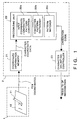
- Fig. 1 is a block diagram showing the construction of a handwritten character recognition apparatus according to an embodiment of the present invention;
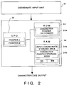
- Fig. 2 is a block diagram showing an example of the hardware configuration according to this embodiment;
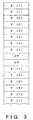
- Fig. 3 is a diagram showing the structure of input coordinate data;
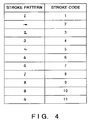
- Fig. 4 is a correlation table showing the correlation between stroke patterns and stroke codes;
- Fig. 5 is a diagram showing the composition of a character pattern dictionary;
- Fig. 6 is a diagram showing eight-direction vectors; and
- Fig. 7 is a flowchart showing a processing procedure.
- An embodiment of the present invention will now be described in detail with reference to the accompanying drawings. In this embodiment, an apparatus which recognizes handwritten characters will be described as one example of a pattern recognition apparatus. Also, in order to simplify the description, a processing procedure performed by this apparatus for recognizing numeral inputs will be discussed.
- Fig. 1 is a block diagram showing the construction of an apparatus for recognizing handwritten characters according to this embodiment.
- As shown in Fig. 1, the apparatus includes an
input block 1 having aninput pen 11 and aninput unit 12. The apparatus further includes aprocessing block 2 comprising acoordinate information memory 21, acharacter recognizing unit 22 and acharacter delimiting controller 23. Theinput unit 12 is an input panel comprising a network of electrodes arrayed horizontally and vertically and enters coordinate data in response to being pressed by theinput pen 11. The coordinate data is delivered to thecoordinate information memory 21. The latter receives and stores the pen coordinate data sent from theinput unit 12 and transmits the character coordinate data to thecharacter recognizing unit 22. The latter comprises an input coordinate/character pattern converter 22a, acharacter pattern dictionary 22b which stores patterns inclusive of two or more compound character patterns, and a pattern matcher 22c. Thecharacter recognizing unit 22 recognizes the character coordinate data from thecoordinate information memory 21 and provides thecharacter delimiting controller 23 with a character code which includes a character-entry continuance code or a character delimiting code. - The input coordinate/
character pattern converter 22a divides one stroke of coordinate data received from thecoordinate information memory 21 into ten equal segments (where one "stroke" of data is that which enters from the start until the pen is raised from the input panel, or which enters from one moment the pen is raised until the next moment the pen is raised), converts the resulting equally divided vectors into vectors in eight directions, as shown in Fig. 6, and converts the vectorized patterns into stroke codes by the conversion table shown in Fig. 4 in order to simplify processing. A vector (jump vector) connecting the end coordinates of the first stroke and the starting coordinates of the second stroke also is similarly converted into vectors in eight directions, thereby converting an input coordinate character into a character pattern. Thecharacter pattern dictionary 22b has the composition shown in Fig. 5. By way of example, the numeral "4" is stored as a character pattern of "5" (stroke code), "3" (jump vector), "1" (stroke code), and an input of successive numerals "12" is stored as a character pattern of "1" (stroke code), "3" (jump vector), "3" (stroke code). The pattern matcher 22c matches the input character pattern, which results from character-pattern conversion by the input coordinate/character pattern converter 22a, with the character patterns in thecharacter pattern dictionary 22b, outputs a character code, which includes the character-entry continuance code or the character delimiting code, as the result of recognition, and sends the character code to thecharacter delimiting controller 23. - Based upon the character code received from the
character recognizing unit 22, thecharacter delimiting controller 23 continues character entry if the character code contains the character-entry continuance code. If the character code contains the character delimiting code, however, thecharacter delimiting controller 23 converts the data which prevails from the moment of code arrival until just before one stroke to corresponding JIS code and outputs the JIS code as one character, and recognizes the data from just before one stroke as the next character. If the character code is the JIS code, the JIS code is outputted from thecharacter delimiting controller 23. Thecharacter delimiting controller 23 contains a converting table (not shown) for converting the character-entry continuance code to the corresponding JIS code. - Each step of this processing will now be described in further detail.
- Fig. 2 is a block diagram illustrating an example of the hardware configuration of this embodiment.
Numeral 31 denotes a coordinate input unit, namely a conventional input panel comprising a network of electrodes arrayed horizontally and vertically, for entering coordinate data in response to being pressed by theinput pen 11. The coordinate data is delivered to a central processing unit (hereinafter referred to as a CPU) 32.. The latter has aROM 33, in which character patterns and a processing procedure in accordance with the flowchart of Fig. 7 are stored in advance, and aRAM 34 for storing processed data. In accordance with the processing procedure stored in theROM 33, theCPU 32 stores coordinate values, which have been entered from the coordinateinput unit 31, in an input-coordinatestorage area 34a of theRAM 34, creates a character pattern from the input coordinate data, stores the character pattern in a character-pattern storage area 34b of theRAM 34, matches this pattern with a character-pattern dictionary 33a stored previously in theROM 33, and outputs a pattern code, which is the result of recognition based upon the pattern matching. TheCPU 32 has pointers n, M, and theRAM 34 a continuance-code storage area BA and a point storage area BM. These are used in the description of the processing procedure given below. - Fig. 3 is a diagram showing the structure of input coordinate data stored in the input-coordinate
storage area 33a ofRAM 33. In Fig. 3, X(1) represents the entered X-coordinate value of the starting point of the first stroke. It is composed of two bytes and has a value of 0 - 7 FFFH. Similarly, Y(1) represents the entered Y-coordinate value of the starting point of the first stroke; X(4) represents the entered X-coordinate value of the end point of the first stroke; and Y(4) represents the entered Y-coordinate value of the end point of the first stroke. "UP", which follows Y(4), is a pen-up code (FFFFH) representing the fact that the pen has been raised from the input panel. It indicates the end to one stroke. X(1) through Y(4) constitute the data of the first stroke. X(5) is the X-coordinate value of the starting point of the second stroke, and Y(5) is the Y-coordinate of the starting point of the second stroke. The coordinate values from X(5) onward constitute the data of the second stroke. - Fig. 4 is a correspondence table showing the correspondence between stroke patterns (actually represented by 10 items of vector data) and stroke codes. A stroke pattern of the type "↓" (the stroke pattern of "1" or a stroke pattern which is part of "4"; 7777777777) is assigned a stroke code "1". For example, when entered patterns are limited to numerals, the stroke patterns are classified as the eleven types of stroke patterns shown in Fig. 4, and all numerals are represented by combinations of eleven types of stroke codes. In case of characters, especially Chinese characters, there is a much wider variety, but these also can be expressed by combinations of stroke codes in the same manner as numerals.
- Fig. 5 is a diagram showing the composition of a
character pattern dictionary 33a. When the stroke pattern "↓" is entered as the data of one stroke, the stroke code from Fig. 4 is "1", and therefore "FF01H" corresponds as the output code. In case of two-stroke data, e.g., character pattern data corresponding to the numeral "4", "1" is the stroke code from Fig. 4, "3" is the jump vector from Fig. 6, and "5" is the stroke code from Fig. 4. Thus, the corresponding output code in Fig. 5 is "2334H" (JIS code). When the numeral "4" is entered, therefore, "2334H" is outputted as the output code. Here "FFXXH" is referred to as a continuance code and indicates the possibility that a further input will be made to form a particular character. "FE00H" is referred to as a character delimiting code and indicates that a compound pattern of two characters has been verified. If a character delimiting code has been outputted, one character preceding the compound pattern is delimited and outputted. - Fig. 6 is a diagram representing the conversion into vectors of eight directions. Specifically, a direction vector is classified, depending upon its angle, as a vector in any of eight directions. For example, a direction vector from left to right is classified as a vector "1", a direction vector toward the upper right is classified as a vector "2", and so on.
- Fig. 7 is a flowchart illustrating the procedure of processing executed by the handwriting character recognition apparatus of the present embodiment. Processing will be described in line with the flowchart of Fig. 7.
- Step S71 of the flowchart calls for initialization of the
RAM 34. That is, the initial value "1" is entered in the pointer n, which indicates the address of the storage location of the input coordinate data, and the initial value "1" is entered in the pointer M, which indicates the address of the storage location of the input coordinate data for performing recognition processing. The location indicated by the initial value "1" is the location of X(1) in case of Fig. 3, namely the beginning of thestorage area 34a for the input coordinate data. - The items of X-, Y-coordinate data are entered from the coordinate
input unit 31 at step S72. In this example, the minimum coordinate values sent by the coordinateinput unit 31 are (0,0), and the maximum coordinate values sent are (320,128). When thepen 11 is not being pressed against the coordinateinput unit 31, the latter sends back the pen-up codes (FFFFH, FFFFH). The pen-up codes are outputted at the moment the pen is raised from the coordinateinput unit 31, and from this point onward no data arrives from the coordinateinput unit 31 until the pen is pressed down. - The input coordinate values (X,Y) are stored in the input-coordinate
storage area 34a of theRAM 34 at step S73. If the value of the pointer n representing the address of the storage location of the input coordinate data is the initial value "1", this is stored at the locations of X(1), Y(1) of Fig. 3. If the value of the pointer n is "2", this is stored at the locations of X(2), Y(2) of Fig. 3. - The value of the point n representing the address of the input-coordinate
storage area 34a is incremented at step S74. If "1" has been stored at X(1), Y(1) at step S73, the value of the point n will be "2" since the pointer n is incremented at step S74. - It is determined at step S75 whether the item of data (X,Y) sent from the coordinate
input unit 31 is the pen-up code (FFFFH,FFFFH). If thepen 11 is not being pressed down on the coordinateinput unit 31, then the pen-up code is sent and entry of one stroke ends. The program then proceeds to step S76 to begin pattern recognition. If thepen 11 is being pressed down on the coordinateinput unit 31, X-, Y-coordinate data other than the pen-up code enters and the program returns to step S72 in to execute input processing of the next item of data. - In case of the pen-up code at step S75, an input character pattern is created from the stored coordinate data at step S76 in accordance with the above-described procedure, the created pattern is matched with the data in the
character pattern dictionary 33a, and a pattern code is outputted. By way of example, assume that "1" has been entered as the first stroke. Since the stroke pattern "↓" has the stroke code "1", as shown in Fig. 4, matching is performed with the stroke code "1" of the character pattern data of the single-stroke character data shown in Fig. 5, and therefore the output code "FF01H" is outputted as the character code. At the moment "1" is entered as the first stroke, it is unclear at this time as to whetherwill be entered next at the same position to form the numeral "4" or whether a subsequent numeral will be entered alongside "1". The character-entry continuance code "FF01H" inclusive of the code "1" is outputted for this reason. Assume that "12" has been entered. Here the stroke pattern "↓" of the first stroke has the stroke code "1" from Fig. 4, the jump vector, namely the vector connecting the coordinates of the end point of the first stroke and the coordinates of the starting point of the second stroke, is the upwardly directed vector "3" from Fig. 6, the stroke pattern of the second stroke is , and therefore the stroke code for this pattern is "3" from Fig. 4. Accordingly, the character pattern data is (1,3,3). Since this is the same as the third item of two-stroke character data in Fig. 5, the output code "FEOOH" (the character delimiting code) is outputted as the character code.
- It is determined at step S77 whether the character code which is the result of pattern recognition is the character-entry continuance code. Since codes such as FF01H, FF02H, FF05H and FF06H are used as character-entry continuance codes, a code greater than FF00H is a character-entry continuance code, in which case the program proceeds to step S80. If the code is less than FF00H, it is not a character-entry continuance code, and therefore the program proceeds to step S78.
- When the stroke pattern "↓" is entered as the first stroke, as in the foregoing example, the character code is the character-entry continuance code "FF01H", and the program proceeds to step S80, where entry of the next stroke is awaited. On the other hand, when the stroke patternis entered as the first stroke, the character code differs from that of the foregoing example and obviously is the JIS code "2332H" for "2". Since this is a code other than a character-entry continuance code, the program proceeds to step S78.

- It is determined at step S78 whether the character code resulting from character recognition is a character delimiting code. Since FE00H is used as the character delimiting code, a code greater than FE00H is a character delimiting code. Therefore, in order to perform delimiting processing of the preceding one character, the program proceeds to step S81. If the code is less than FE00H, the code is other than a character delimiting code, and therefore the program proceeds to step S79.
- The character code resulting from character recognition is outputted to the exterior of the apparatus at step S79.
- The current status of character recognition is stored at step S80. The continuance code outputted at step S76 is stored in the continuance code storage area BA of
RAM 34, which area stores the character code currently undergoing recognition. The value of pointer n of the next item of input data is stored in the point storage area BM ofRAM 34, which area stores the content of the pointer of the input coordinate data currently undergoing recognition. When the stroke pattern "↓" is entered as the first stroke, as in the foregoing example, the character code "FF01H" is outputted at step S76 and the program proceeds to step S80. At step S80, therefore, "FF01H" is stored in the continuance code storage area BA. When the input coordinate data is as shown in Fig. 3, data from X(1) to the UP position is stored. Accordingly, the value of the pointer n is "6", which indicates the position of X(5), and "6" is stored in the point storage area BM. - At step S81, the input data up to two strokes previous is recognized as one character and a character code is outputted. Further, data from one stroke previous is treated as the next character and recognition is performed again. First, the value in the continuance code storage area BA currently undergoing recognition (which value was stored at step S80) is converted into a JIS character code, and this code is outputted. Next, since the data to be recognized is the input coordinate data following that which has undergone character delimiting, the value of the point storage area BM of the input coordinate data currently undergoing recognition (which value was stored at step S80) is inputted to the pointer M representing the address of the input coordinate data to undergo recognition processing.
- When "12" is entered in the previous example, first "FF01H" is outputted at step S76 at the moment "1" is entered, and "FF01H" is stored in the continuance code storage area BA. The value of the pointer n at this time is "6", which represents the location of X(5) in Fig. 3, and "6" is stored in the point storage area BM. Next, at the moment "2" is entered, the character pattern is (1,3,3), and "FE00H" is outputted at step S76. At step S81, the value of the continuance code storage area BA is "FF01H", and therefore this is outputted upon being converted into "2331H", which is the JIS code of "1". Also, the value "6" of the point storage area BM is inputted to the pointer M. At the next step S76, recognition is performed from the location of X(5) in Fig. 3, namely from the beginning of the "2" pattern.
- Thus, as described above, the character sequence entered successively as "12" is treated as the two characters "1" and "2" so that the characters can be delimited and recognized.
- In the embodiment set forth above, processing regarding entry of numerals is described. However, it goes without saying that similar processing can be realized with regard also to hiragana and katakana syllables in the Japanese language, alphabetic characters in the English language, Chinese characters, etc., by increasing the stroke patterns of Fig. 4 and the character pattern dictionary of Fig. 5.
- Thus, in accordance with the present invention as described above, character recognizing means having a character pattern dictionary which includes compound-character patterns of two or more characters is provided. This makes it possible to provide an on-line character delimiting apparatus for handwritten characters, in which even if characters in a sequence are entered at any desired positions in a natural manner without any restriction in terms of time, the characters are delimited correctly one at a time so that character recognition can be performed in an outstanding manner.
- As many apparently widely different embodiments of the present invention can be made without departing from the scope thereof, it is to be understood that the invention is not limited to the specific embodiments thereof.
Claims (6)
- A pattern recognition method comprising the steps of:generating coordinate data (S72,S73,S74,S75) for at least one pattern to be recognised, the or each pattern comprising one or more sequential handwritten strokes; andrecognising the or each pattern (S76,S77,S78) by comparing (S76) strokes of said coordinate data with stroke data stored in a dictionary (22b);characterised in that the stroke data stored in said dictionary (22b) is stored as a table of code data for stroke pattern data and jump vector data, the stroke pattern data defining a plurality of individual strokes each having a unique stroke pattern from a start coordinate to an end coordinate of the stroke, the jump vector data representing a direction from an end coordinate of one stroke to a start coordinate of the next sequential stroke, the code data indicating whether or not a stroke pattern data or a string of stroke pattern data and jump vector data comprises an individual pattern;in that the step of generating coordinate data (S72,S73,S74,S75) includes the step (S75) of forming stroke pattern data and jump vector data for the or each pattern to be recognised; andin that the step of recognising the or each pattern (S76,S77,S78) comprises the steps ofmatching (S76) the stroke pattern data and jump vector data for the or each pattern to be recognised with the stroke pattern data and jump vector data in said dictionary (22b) to obtain corresponding code data for the matched stroke pattern data and jump vector data; andoutputting (S79) a pattern code for an individual pattern when said code data indicates that the matched stroke pattern data and jump vector data comprises an individual pattern.
- A method as claimed in claim 1 wherein said code data includes continuance codes for indicating whether the stroke pattern data represents part of an individual pattern, said step of recognising (S76,S77,S78) including the steps of waiting (S77,S80) for a jump vector data and a stroke pattern data to be formed for the next sequential stroke when a said continuance code is output from said dictionary (22b), and matching a string of stroke pattern data and jump vector data for a pattern to be recognised with a string of stroke pattern data and jump vector data in said dictionary (22b).
- A method as claimed in claim 1 or claim 2 wherein said code data includes delimiting codes for indicating whether a string of stroke pattern data and jump vector data represents an end of an individual pattern, the step of recognising (S76,S77,S78) including the steps of outputting (S81) a code for an individual pattern when a said delimiting code is output from said dictionary (22b) and waiting for a jump vector data and a stroke pattern data to be formed for the first stroke for the next individual pattern.
- Pattern recognition apparatus comprising:coordinate data memory means (21) for storing coordinate data for at least one pattern to be recognised, the or each pattern comprising one or more sequential handwritten strokes;a dictionary (22b) for storing stroke data; andpattern recognising means (22,23) for recognising the or each pattern by comparing strokes of said coordinate data with stroke data in said dictionary (22b);characterised in that said dictionary (22b) is arranged to store a table of code data for stroke pattern data and jump vector data, the stroke pattern data defining a plurality of individual strokes each having a unique stroke pattern from a start coordinate to an end coordinate of the stroke, the jump vector data representing a direction from an end coordinate of one stroke to a start coordinate of the next sequential stroke, the code data indicating whether or not a stroke pattern data or a string of stroke pattern data and jump vector data comprises an individual pattern; andin that said pattern recognising means (22,23) comprises:converter means (22a) for forming stroke pattern data and jump vector data for the or each pattern to be recognised from the coordinate data;matching means (22c) for matching the stroke pattern data and jump vector data for the or each pattern to be recognised with the stroke pattern data and jump vector data in said dictionary (22b) to obtain corresponding code data for the matched stroke pattern data and jump vector data; andmeans (23) for outputting a pattern code for an individual pattern when said code data indicates that the matched stroke pattern data and jump vector data comprises an individual pattern.
- Pattern recognition apparatus as claimed in claim 4 wherein said code data includes continuance codes for indicating whether the stroke pattern data represents part of an individual pattern; said output means (23) being arranged to wait for a jump vector data and a stroke pattern data to be formed for the next sequential stroke when a said continuance code is output from said dictionary (22b); said matching means (22c) being arranged to match a string of stroke pattern data and jump vector data for a pattern to be recognised with a string of stroke pattern data and jump vector data in said dictionary (22b).
- Pattern recognition apparatus as claimed in claim 4 or claim 5 wherein said code data includes delimiting codes for indicating whether a string of stroke pattern data and jump vector data represents an end of an individual pattern.
Applications Claiming Priority (2)
| Application Number | Priority Date | Filing Date | Title |
|---|---|---|---|
| JP137277/90 | 1990-05-29 | ||
| JP02137277A JP3143461B2 (en) | 1990-05-29 | 1990-05-29 | Character recognition method and character recognition device |
Publications (3)
| Publication Number | Publication Date |
|---|---|
| EP0459746A2 EP0459746A2 (en) | 1991-12-04 |
| EP0459746A3 EP0459746A3 (en) | 1993-07-21 |
| EP0459746B1 true EP0459746B1 (en) | 1997-03-12 |
Family
ID=15194917
Family Applications (1)
| Application Number | Title | Priority Date | Filing Date |
|---|---|---|---|
| EP91304791A Expired - Lifetime EP0459746B1 (en) | 1990-05-29 | 1991-05-28 | Pattern recognition method, and apparatus therefor |
Country Status (4)
| Country | Link |
|---|---|
| US (1) | US5533147A (en) |
| EP (1) | EP0459746B1 (en) |
| JP (1) | JP3143461B2 (en) |
| DE (1) | DE69125054T2 (en) |
Families Citing this family (41)
| Publication number | Priority date | Publication date | Assignee | Title |
|---|---|---|---|---|
| JPH07295940A (en) * | 1994-04-21 | 1995-11-10 | Sharp Corp | Electronic equipment |
| US6292181B1 (en) | 1994-09-02 | 2001-09-18 | Nec Corporation | Structure and method for controlling a host computer using a remote hand-held interface device |
| US5867106A (en) * | 1994-09-02 | 1999-02-02 | Packard Bell Nec | Password switch to override remote control |
| US6137473A (en) * | 1994-09-02 | 2000-10-24 | Nec Corporation | System and method for switching control between a host computer and a remote interface device |
| US6209034B1 (en) | 1994-09-02 | 2001-03-27 | Nec Corporation | Remote keyboard macros activated by hot icons |
| US6092117A (en) * | 1994-09-02 | 2000-07-18 | Packard Bell Nec | System and method for automatically reconnecting a wireless interface device to a host computer |
| US6279153B1 (en) | 1995-10-16 | 2001-08-21 | Nec Corporation | Multi-user flash ROM update |
| US6018806A (en) * | 1995-10-16 | 2000-01-25 | Packard Bell Nec | Method and system for rebooting a computer having corrupted memory using an external jumper |
| US6126327A (en) * | 1995-10-16 | 2000-10-03 | Packard Bell Nec | Radio flash update |
| US6330231B1 (en) | 1995-10-16 | 2001-12-11 | Nec Corporation | Dynamic server allocation for load balancing wireless remote interface processing |
| US5990875A (en) * | 1995-10-16 | 1999-11-23 | Packard Bell Nec | Double pen up event |
| US6664982B1 (en) | 1995-10-16 | 2003-12-16 | Nec Corporation | Multi-user on-screen keyboard |
| US6724372B1 (en) | 1995-10-16 | 2004-04-20 | Nec Corporation | Ink trails on a wireless remote interface tablet and wireless remote ink field object |
| US6148344A (en) * | 1995-10-16 | 2000-11-14 | Nec Corporation | System and method for enabling an IPX driver to accommodate multiple LAN adapters |
| US6005533A (en) * | 1995-10-16 | 1999-12-21 | Packard Bell Nec | Remote occlusion region |
| US6353599B1 (en) | 1995-10-16 | 2002-03-05 | Nec Corporation | Wireless enumeration |
| US5996082A (en) * | 1995-10-16 | 1999-11-30 | Packard Bell Nec | System and method for delaying a wake-up signal |
| US6141688A (en) * | 1995-10-16 | 2000-10-31 | Nec Corporation | Broadcast search for available host |
| JPH09319829A (en) * | 1996-06-03 | 1997-12-12 | Nec Corp | Online character recognition device |
| US6370269B1 (en) * | 1997-01-21 | 2002-04-09 | International Business Machines Corporation | Optical character recognition of handwritten or cursive text in multiple languages |
| US6215901B1 (en) * | 1997-03-07 | 2001-04-10 | Mark H. Schwartz | Pen based computer handwriting instruction |
| US6144764A (en) * | 1997-07-02 | 2000-11-07 | Mitsui High-Tec, Inc. | Method and apparatus for on-line handwritten input character recognition and recording medium for executing the method |
| KR100454541B1 (en) * | 1998-04-27 | 2004-11-03 | 산요덴키가부시키가이샤 | Method and system of handwritten-character recognition |
| US7750891B2 (en) | 2003-04-09 | 2010-07-06 | Tegic Communications, Inc. | Selective input system based on tracking of motion parameters of an input device |
| US7286115B2 (en) * | 2000-05-26 | 2007-10-23 | Tegic Communications, Inc. | Directional input system with automatic correction |
| US7030863B2 (en) | 2000-05-26 | 2006-04-18 | America Online, Incorporated | Virtual keyboard system with automatic correction |
| US7821503B2 (en) * | 2003-04-09 | 2010-10-26 | Tegic Communications, Inc. | Touch screen and graphical user interface |
| CA2392446C (en) * | 1999-05-27 | 2009-07-14 | America Online Incorporated | Keyboard system with automatic correction |
| US7610194B2 (en) * | 2002-07-18 | 2009-10-27 | Tegic Communications, Inc. | Dynamic database reordering system |
| US6970599B2 (en) * | 2002-07-25 | 2005-11-29 | America Online, Inc. | Chinese character handwriting recognition system |
| JP3974359B2 (en) * | 2000-10-31 | 2007-09-12 | 株式会社東芝 | Online character recognition apparatus and method, computer-readable storage medium, and online character recognition program |
| JP4061094B2 (en) * | 2002-03-15 | 2008-03-12 | インターナショナル・ビジネス・マシーンズ・コーポレーション | Speech recognition apparatus, speech recognition method and program thereof |
| US7590386B2 (en) * | 2002-04-18 | 2009-09-15 | Interdigital Technology Corporation | Method for control of contention-based wireless access |
| JP2007312250A (en) * | 2006-05-19 | 2007-11-29 | Canon Inc | Web information processing apparatus and method, information processing apparatus, and control method of information processing apparatus |
| JP4372119B2 (en) * | 2006-05-19 | 2009-11-25 | キヤノン株式会社 | Web information processing apparatus and Web information processing method |
| US8225203B2 (en) * | 2007-02-01 | 2012-07-17 | Nuance Communications, Inc. | Spell-check for a keyboard system with automatic correction |
| US8201087B2 (en) | 2007-02-01 | 2012-06-12 | Tegic Communications, Inc. | Spell-check for a keyboard system with automatic correction |
| CN101561725B (en) * | 2008-04-16 | 2010-12-08 | 汉王科技股份有限公司 | Method and system of fast handwriting input |
| US8150160B2 (en) * | 2009-03-26 | 2012-04-03 | King Fahd University Of Petroleum & Minerals | Automatic Arabic text image optical character recognition method |
| JP6195333B2 (en) | 2012-08-08 | 2017-09-13 | キヤノン株式会社 | Robot equipment |
| US10725650B2 (en) * | 2014-03-17 | 2020-07-28 | Kabushiki Kaisha Kawai Gakki Seisakusho | Handwritten music sign recognition device and program |
Family Cites Families (17)
| Publication number | Priority date | Publication date | Assignee | Title |
|---|---|---|---|---|
| CH591726A5 (en) * | 1973-07-30 | 1977-09-30 | Nederlanden Staat | |
| JPS60136892A (en) * | 1983-12-26 | 1985-07-20 | Hitachi Ltd | On-line recognition device of hand written graphic |
| US4731857A (en) * | 1984-06-29 | 1988-03-15 | International Business Machines Corporation | Recognition system for run-on handwritten characters |
| US4764972A (en) * | 1985-05-23 | 1988-08-16 | Nec Corporation | Continuous characters recognition system |
| JPS6282486A (en) * | 1985-10-08 | 1987-04-15 | Hitachi Ltd | Recognizing device for online handwritten graphic form |
| JPH0766418B2 (en) * | 1985-11-20 | 1995-07-19 | 三洋電機株式会社 | Handwriting recognition device |
| JPS62193758A (en) * | 1986-02-21 | 1987-08-25 | Y K Trading Kk | Surface polishing attachment |
| US5157737A (en) * | 1986-07-25 | 1992-10-20 | Grid Systems Corporation | Handwritten keyboardless entry computer system |
| JPS63193759A (en) * | 1987-02-06 | 1988-08-11 | Fujitsu Ltd | High ac impedance circuit |
| US4953225A (en) * | 1987-10-16 | 1990-08-28 | Sharp Kabushiki Kaisha | Handwritten character-recognizing apparatus for automatically generating and displaying character frames |
| JP2619429B2 (en) * | 1987-11-05 | 1997-06-11 | グローリー工業株式会社 | How to separate contact characters |
| JP2777890B2 (en) * | 1988-04-15 | 1998-07-23 | 富士通株式会社 | Handwritten character extraction method |
| US5001765A (en) * | 1989-01-05 | 1991-03-19 | International Business Machines Corporation | Fast spatial segmenter for handwritten characters |
| US5029223A (en) * | 1990-02-02 | 1991-07-02 | International Business Machines Corporation | Constraint driven-on line recognition of handwritten characters and symbols |
| JP3095145B2 (en) * | 1990-06-14 | 2000-10-03 | ソニー株式会社 | Information processing device |
| US5121441A (en) * | 1990-09-21 | 1992-06-09 | International Business Machines Corporation | Robust prototype establishment in an on-line handwriting recognition system |
| US5216725A (en) * | 1990-10-31 | 1993-06-01 | Environmental Research Institute Of Michigan | Apparatus and method for separating handwritten characters by line and word |
-
1990
- 1990-05-29 JP JP02137277A patent/JP3143461B2/en not_active Expired - Fee Related
-
1991
- 1991-05-28 DE DE69125054T patent/DE69125054T2/en not_active Expired - Fee Related
- 1991-05-28 EP EP91304791A patent/EP0459746B1/en not_active Expired - Lifetime
-
1994
- 1994-11-02 US US08/334,003 patent/US5533147A/en not_active Expired - Lifetime
Also Published As
| Publication number | Publication date |
|---|---|
| EP0459746A3 (en) | 1993-07-21 |
| US5533147A (en) | 1996-07-02 |
| EP0459746A2 (en) | 1991-12-04 |
| JPH0431988A (en) | 1992-02-04 |
| DE69125054T2 (en) | 1997-07-17 |
| JP3143461B2 (en) | 2001-03-07 |
| DE69125054D1 (en) | 1997-04-17 |
Similar Documents
| Publication | Publication Date | Title |
|---|---|---|
| EP0459746B1 (en) | Pattern recognition method, and apparatus therefor | |
| KR100297482B1 (en) | Method and apparatus for character recognition of hand-written input | |
| US5113452A (en) | Hand-written character recognition apparatus and method | |
| JPH02266485A (en) | Information recognizing device | |
| US5659633A (en) | Character recognition method utilizing compass directions and torsion points as features | |
| KR19980058361A (en) | Korean Character Recognition Method and System | |
| KR100301216B1 (en) | Online text recognition device | |
| JPS62271086A (en) | Pattern recognizing device | |
| JP2851865B2 (en) | Character recognition device | |
| JP2922206B2 (en) | Online handwriting recognition system | |
| JPH01316889A (en) | Handwritten character recognizing system | |
| JPH0210473B2 (en) | ||
| JPH09179935A (en) | Character recognition device and control method therefor | |
| JPH0830717A (en) | Character recognition method and device therefor | |
| JPS5914081A (en) | Device for recognizing on-line hand-writing character | |
| JPH09167208A (en) | On-line character recognizing device | |
| JPS6055481A (en) | Pattern recognizing device | |
| JPS58101377A (en) | On-line manuscript character input device | |
| JPH01169588A (en) | On-line character recognizing device | |
| JPH0371322A (en) | Continuous command processing system | |
| JPS62216092A (en) | Online hand-written character recognizing system | |
| JPH06301819A (en) | Online handwritten character recognition device | |
| JPS61288284A (en) | Direction code collating system | |
| JPH0264884A (en) | Dictionary retrieval circuit for character recognizing device | |
| JPS63106089A (en) | Online hand-written character recognizing and processing circuit |
Legal Events
| Date | Code | Title | Description |
|---|---|---|---|
| PUAI | Public reference made under article 153(3) epc to a published international application that has entered the european phase |
Free format text: ORIGINAL CODE: 0009012 |
|
| AK | Designated contracting states |
Kind code of ref document: A2 Designated state(s): DE FR GB IT NL |
|
| PUAL | Search report despatched |
Free format text: ORIGINAL CODE: 0009013 |
|
| RHK1 | Main classification (correction) |
Ipc: G06K 9/22 |
|
| AK | Designated contracting states |
Kind code of ref document: A3 Designated state(s): DE FR GB IT NL |
|
| 17P | Request for examination filed |
Effective date: 19931208 |
|
| 17Q | First examination report despatched |
Effective date: 19950524 |
|
| GRAG | Despatch of communication of intention to grant |
Free format text: ORIGINAL CODE: EPIDOS AGRA |
|
| GRAH | Despatch of communication of intention to grant a patent |
Free format text: ORIGINAL CODE: EPIDOS IGRA |
|
| GRAH | Despatch of communication of intention to grant a patent |
Free format text: ORIGINAL CODE: EPIDOS IGRA |
|
| GRAA | (expected) grant |
Free format text: ORIGINAL CODE: 0009210 |
|
| AK | Designated contracting states |
Kind code of ref document: B1 Designated state(s): DE FR GB IT NL |
|
| REF | Corresponds to: |
Ref document number: 69125054 Country of ref document: DE Date of ref document: 19970417 |
|
| ET | Fr: translation filed | ||
| ITF | It: translation for a ep patent filed |
Owner name: SOCIETA' ITALIANA BREVETTI S.P.A. |
|
| PLBE | No opposition filed within time limit |
Free format text: ORIGINAL CODE: 0009261 |
|
| STAA | Information on the status of an ep patent application or granted ep patent |
Free format text: STATUS: NO OPPOSITION FILED WITHIN TIME LIMIT |
|
| 26N | No opposition filed | ||
| REG | Reference to a national code |
Ref country code: GB Ref legal event code: IF02 |
|
| PGFP | Annual fee paid to national office [announced via postgrant information from national office to epo] |
Ref country code: NL Payment date: 20050513 Year of fee payment: 15 |
|
| PGFP | Annual fee paid to national office [announced via postgrant information from national office to epo] |
Ref country code: IT Payment date: 20060531 Year of fee payment: 16 |
|
| PG25 | Lapsed in a contracting state [announced via postgrant information from national office to epo] |
Ref country code: NL Free format text: LAPSE BECAUSE OF NON-PAYMENT OF DUE FEES Effective date: 20061201 |
|
| NLV4 | Nl: lapsed or anulled due to non-payment of the annual fee |
Effective date: 20061201 |
|
| PGFP | Annual fee paid to national office [announced via postgrant information from national office to epo] |
Ref country code: DE Payment date: 20090531 Year of fee payment: 19 Ref country code: FR Payment date: 20090520 Year of fee payment: 19 |
|
| PG25 | Lapsed in a contracting state [announced via postgrant information from national office to epo] |
Ref country code: IT Free format text: LAPSE BECAUSE OF NON-PAYMENT OF DUE FEES Effective date: 20070528 |
|
| PGFP | Annual fee paid to national office [announced via postgrant information from national office to epo] |
Ref country code: GB Payment date: 20090527 Year of fee payment: 19 |
|
| GBPC | Gb: european patent ceased through non-payment of renewal fee |
Effective date: 20100528 |
|
| REG | Reference to a national code |
Ref country code: FR Ref legal event code: ST Effective date: 20110131 |
|
| PG25 | Lapsed in a contracting state [announced via postgrant information from national office to epo] |
Ref country code: DE Free format text: LAPSE BECAUSE OF NON-PAYMENT OF DUE FEES Effective date: 20101201 |
|
| PG25 | Lapsed in a contracting state [announced via postgrant information from national office to epo] |
Ref country code: FR Free format text: LAPSE BECAUSE OF NON-PAYMENT OF DUE FEES Effective date: 20100531 |
|
| PG25 | Lapsed in a contracting state [announced via postgrant information from national office to epo] |
Ref country code: GB Free format text: LAPSE BECAUSE OF NON-PAYMENT OF DUE FEES Effective date: 20100528 |