EP0462432B1 - Integrated process control valve - Google Patents
Integrated process control valve Download PDFInfo
- Publication number
- EP0462432B1 EP0462432B1 EP91108859A EP91108859A EP0462432B1 EP 0462432 B1 EP0462432 B1 EP 0462432B1 EP 91108859 A EP91108859 A EP 91108859A EP 91108859 A EP91108859 A EP 91108859A EP 0462432 B1 EP0462432 B1 EP 0462432B1
- Authority
- EP
- European Patent Office
- Prior art keywords
- signals
- valve
- fluid
- producing
- pressure
- Prior art date
- Legal status (The legal status is an assumption and is not a legal conclusion. Google has not performed a legal analysis and makes no representation as to the accuracy of the status listed.)
- Expired - Lifetime
Links
Images


Classifications
-
- G—PHYSICS
- G05—CONTROLLING; REGULATING
- G05D—SYSTEMS FOR CONTROLLING OR REGULATING NON-ELECTRIC VARIABLES
- G05D7/00—Control of flow
- G05D7/06—Control of flow characterised by the use of electric means
- G05D7/0617—Control of flow characterised by the use of electric means specially adapted for fluid materials
- G05D7/0629—Control of flow characterised by the use of electric means specially adapted for fluid materials characterised by the type of regulator means
- G05D7/0635—Control of flow characterised by the use of electric means specially adapted for fluid materials characterised by the type of regulator means by action on throttling means
-
- F—MECHANICAL ENGINEERING; LIGHTING; HEATING; WEAPONS; BLASTING
- F16—ENGINEERING ELEMENTS AND UNITS; GENERAL MEASURES FOR PRODUCING AND MAINTAINING EFFECTIVE FUNCTIONING OF MACHINES OR INSTALLATIONS; THERMAL INSULATION IN GENERAL
- F16K—VALVES; TAPS; COCKS; ACTUATING-FLOATS; DEVICES FOR VENTING OR AERATING
- F16K31/00—Actuating devices; Operating means; Releasing devices
- F16K31/12—Actuating devices; Operating means; Releasing devices actuated by fluid
- F16K31/122—Actuating devices; Operating means; Releasing devices actuated by fluid the fluid acting on a piston
-
- F—MECHANICAL ENGINEERING; LIGHTING; HEATING; WEAPONS; BLASTING
- F16—ENGINEERING ELEMENTS AND UNITS; GENERAL MEASURES FOR PRODUCING AND MAINTAINING EFFECTIVE FUNCTIONING OF MACHINES OR INSTALLATIONS; THERMAL INSULATION IN GENERAL
- F16K—VALVES; TAPS; COCKS; ACTUATING-FLOATS; DEVICES FOR VENTING OR AERATING
- F16K37/00—Special means in or on valves or other cut-off apparatus for indicating or recording operation thereof, or for enabling an alarm to be given
- F16K37/0025—Electrical or magnetic means
- F16K37/005—Electrical or magnetic means for measuring fluid parameters
-
- Y—GENERAL TAGGING OF NEW TECHNOLOGICAL DEVELOPMENTS; GENERAL TAGGING OF CROSS-SECTIONAL TECHNOLOGIES SPANNING OVER SEVERAL SECTIONS OF THE IPC; TECHNICAL SUBJECTS COVERED BY FORMER USPC CROSS-REFERENCE ART COLLECTIONS [XRACs] AND DIGESTS
- Y10—TECHNICAL SUBJECTS COVERED BY FORMER USPC
- Y10T—TECHNICAL SUBJECTS COVERED BY FORMER US CLASSIFICATION
- Y10T137/00—Fluid handling
- Y10T137/2278—Pressure modulating relays or followers
- Y10T137/2409—With counter-balancing pressure feedback to the modulating device
-
- Y—GENERAL TAGGING OF NEW TECHNOLOGICAL DEVELOPMENTS; GENERAL TAGGING OF CROSS-SECTIONAL TECHNOLOGIES SPANNING OVER SEVERAL SECTIONS OF THE IPC; TECHNICAL SUBJECTS COVERED BY FORMER USPC CROSS-REFERENCE ART COLLECTIONS [XRACs] AND DIGESTS
- Y10—TECHNICAL SUBJECTS COVERED BY FORMER USPC
- Y10T—TECHNICAL SUBJECTS COVERED BY FORMER US CLASSIFICATION
- Y10T137/00—Fluid handling
- Y10T137/7722—Line condition change responsive valves
- Y10T137/7758—Pilot or servo controlled
- Y10T137/7761—Electrically actuated valve
Definitions
- the invention relates to a process control valve having integrated therewith a plurality of sensors for sensing various physical parameters of the fluid flowing through the valve, and a controller for controlling operation of the valve.
- a process control valve comprising a fluid valve body having a fluid flow passage including an inlet for receiving fluid and an outlet for discharging fluid.
- a controllable throttling element is actuated by means of an actuator means coupled to the valve body and responsive to control signals for selectively moving the throttling element.
- a first pressure sensor is disposed at the inlet of the valve and a second pressure sensor is disposed at the outlet of the valve.
- the pressure signals derived therefrom are sent to a controller for developing an output dependent upon the received signals.
- the controller determines the fluid pressure drop across the valve body, compares the measured fluid pressure drop with a stored predetermined fluid pressure drop value and sends a corresponding difference signal to the actuator in order to match the actual fluid pressure drop value with the stored predetermined fluid pressure drop value.
- an integrated process control valve which includes a valve body having an inlet for receiving fluid, an outlet for discharging fluid, a fluid flow passage connecting the inlet and outlet, and a throttling element which is movable to selectively vary the flow rate of fluid flowing through the passage.
- An actuator is coupled to the valve body and is responsive to control signals for selectively moving the throttling element.
- a first pressure sensor is disposed at the inlet of the valve body for producing a first signal representing the pressure of the fluid at the inlet, and a second pressure sensor is disposed at the outlet of the valve body for producing a second signal representing the pressure of the fluid at the outlet.
- a utilization device receives and processes the first and second signals and develops control signals for application to the actuator to cause the actuator to move the throttling element in a manner dependent upon the values of the first and second signals.
- the utilization device includes a video display screen for displaying representations of the first and second signals.
- representations include graphic "signatures” showing various measured values of the first and second signals for various positions of the throttling element.
- These "measured" signatures may be displayed on the display screen along side of predetermined and previously stored “correct” signatures for enabling the user to determine if the valve is operating properly.
- signatures may be developed and displayed showing various measured parameters of the valve and valve command signals. For example, if pneumatic control signals are used for causing the actuator to move the throttling element, signatures may be developed and displayed of the values of the pneumatic control signals for various positions of the throttling element.
- a temperature sensor is disposed in the valve body to produce a third signal representing the temperature of the fluid in the fluid flow passage, and a throttling element position sensor is coupled to the throttling element to produce a fourth signal representing the position of the throttling element.
- the first, second, third and fourth signals are processed, along with certain predetermined parameters which characterize the shape, size, etc., of the valve body being employed, to develop a measure of the flow rate of fluid flowing through the fluid flow passage.
- FIG. 1 there is shown one illustrative embodiment of an integrated process control valve made in accordance with the present invention.
- the valve includes a valve body 4 having an inlet 8, an outlet 12, and a fluid flow passage 16 connecting the inlet and outlet.
- a central opening 20 Formed centrally in the valve body 4 is a central opening 20 circumscribed by a valve seat 24 for receiving a valve plug 28.
- the valve plug 28 is coupled to the lower end of a valve stem 32 which extends upwardly and out of the valve body 4 to a location within a cylinder 36 which is part of an actuator 40 disposed on the top of the valve body.
- the actuator 40 also includes a yoke 44 on which the cylinder 36 is disposed, and which, in turn, is fitted onto a bonnet 48 disposed in an opening 52 in the top of the valve body 4.
- a bonnet flange 56, and bolts 60 hold the bonnet 48 in place in the opening 52.
- the stem 32 extends upwardly through the bonnet 48 and is held slidably in place by an upper guide 62 and a lower guide 63, which are surrounded by the bonnet.
- the valve stem 32 extends also through the yoke 44 and into the cylinder 36 where a piston 68 is disposed on the upper end of the stem.
- the cylinder 36 includes openings 72 and 76 for receiving air under pressure into the interior of the cylinder, both above and below the piston 68, to thereby control the positioning of the piston 68 in the cylinder and thus the position of the plug 28. That is, when air supplied to opening 72 is under greater pressure than that supplied to opening 76, the piston 68 is forced downwardly, and vice versa.
- valve positioner 80 which receives air under pressure from an air supply 84 and, in response to an electrical control signal supplied via line 88 from a controller 120, develops a control pressure by which air under pressure is selectively directed to either the opening 72 or the opening 76 in the cylinder 36.
- the positioner 80 includes an arm 92 coupled to a stem clamp 94 which, in turn, is coupled to the stem 32 so that each change of position of the plug 28 and thus of the stem 32 may be detected by the positioner.
- the position of the stem 32, as detected by the arm 92, is mechanically converted into a force (represented, for example, by distortion of a spring) and then compared to a force representing an input signal from the controller 120 supplied over lead 88, to ascertain the difference in values of the forces.
- the positioner 80 then causes the piston 68 to move until the signal values match, indicating that the piston, and thus plug 28, has been moved to the correct position.
- the position of the stem 32, and thus plug 28, is detected by the controller 120 via a position sensor arm 96 pivotally mounted to the controller and coupled to the stem clamp 94.
- An angular position sensor disposed in the controller 120 detects the angular position of the arm 96 and thus the position of the stem 32. This information is made available to the controller 120.
- a pressure sensor 104 Disposed in the valve body 4 are a number of sensors, including a pressure sensor 104 disposed in the side wall of the fluid flow passage 16, near the inlet 8, and at a location where the axial side walls of the passage are generally linear or uncurved. The purpose of this is to locate the sensor 104 at a place in the valve body 4 a repeatable, continuous pressure measurement can be made, unaffected by flow problems. This is best accomplished at an axially linear portion of the passage 16.
- a second pressure sensor 108 is located at the outlet 12 of the valve body 4, again on the side wall, and at a location where the axis of the fluid flow generates substantially repeatable, continuous pressures.
- the sensors 104 and 108 are located on the side of the passage 16, rather than at the bottom or at the top, to avoid contamination and interference by debris and scales flowing along the bottom or gas bubbles flowing along the top.
- the pressure sensors 104 and 108 could be any of a variety of fluid pressure sensors such as a conventional diaphragm strain gauge.
- the pressure sensors 104 and 108 produce signals which are carried by lines 112 and 116 respectively to a controller 120 which is mounted on the side of the yoke 44.
- the pressure signals would comprise voltage levels for supply to the controller 120 for initial storage and ultimate processing.
- the controller 120 could advantageously be a microprocessor such as the Intel 8032 microcontroller or the Motorola 68332 microprocessor.
- a temperature sensor 124 for sensing the temperature of the fluid flowing in the passage.
- the sensor 124 might illustratively be a thermocouple temperature sensor suitable for measuring temperatures over a wide range.
- the temperature sensor 124 produces a signal which is supplied by line 128 also to the controller 120.
- a cavitation sensor 132 Disposed on the downstream side of the valve seat 24 in the fluid flow passage 16 is a cavitation sensor 132.
- This sensor develops a signal representing the cavitation or turbulence taking place in the narrowest part of the passage 16 (vena contracta) where such cavitation is of concern.
- the signal so developed is supplied via line 136 to the controller 120.
- the cavitation sensor 132 is a conventional sensing device such as accelerometer or an acoustic transducer.
- Two air pressure sensors are provided in the cylinder 36 of the actuator 40, including a sensor 140 for sensing the air pressure above the piston 68 and a sensor 144 for sensing the pressure below the piston, both in the cylinder 36. Signals developed by sensors 140 and 144, representing the detected air pressures, are supplied via lines 142 and 144 respectively to the controller 120.
- controller 120 Other parameters which may be sensed and utilized by the controller 120 are the pressure of the air from the air supply 84, (characterizing signal supplied over line 148 to the controller) the position of the piston 68 and thus stem 32 as determined by the arm 92 (characterizing signal supplied over line 152), and a control pressure produced by the positioner 80 in response to the electrical signals supplied over line 88 (characterizing signal supplied by the positioner 80 over line 156).
- a number of the parameters sensed for the valve shown in FIG. 1 are specific to the particular valve structure thereshown. It should be understood that a variety of other parameters could likewise be sensed or detected by built-in sensing devices if other valve structures were employed. Signals representing these parameters could also be supplied to the controller 120 as desired by the user.
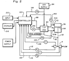
- FIG. 2 there is shown a schematic diagram of the integrated process control valve of FIG. 1, with the valve body shown at 4 in diagrammatic form, the valve stem being shown at 32, the cylinder of the actuator being shown at 36, the piston being shown at 68, the positioner at 80, and the positioner arm at 92.
- Other parts of FIG. 2 corresponding to the FIG. 1 apparatus are the controller 120 (but not shown mounted on the side of the yoke as in FIG.
- a position sensor line 152 for carrying signals to the controller representing the position of the piston 168
- a control pressure line 156 for carrying signals representing the control pressure developed by the positioner 80
- a control signal line 88 for carrying the electrical control signals from the controller to the positioner
- an air supply pressure line 148 for carrying signals representing the pressure of air supplied by the supply 84
- valve inlet and outlet pressure lines 112 and 116 respectively for carrying signals representing the fluid pressure at the inlet of the valve body 4 and at the outlet of the valve body
- a temperature sensing line 128 for carrying signals representing the temperature of the fluid in the valve body 4
- a cavitation sensing line 136 for carrying signals representing the cavitation occurring in the vena contracta of the valve body 4, all as previously discussed.
- the air pressure in the cylinder 36 above the piston 68 is determined by a pressure sensor 140 shown located in an input air pressure line 204 (rather than in the sidewall of the cylinder 36 as in FIG. 1), and the air pressure in the cylinder 36 below the piston 68 is determined by a pressure sensor 144 shown located in an input pressure line 208.
- the controller 120 is programmed to read, store and process the signals supplied by the various sensors, as desired by the user, and then may signal the positioner 80 to change the position of the piston 68 and thus the position of the plug 28 (FIG. 1) to bring the valve in conformance with certain predetermined characteristics. For example, predetermined inlet pressures P 1 , and outlet pressures P 2 , or a predetermined temperature T could be keyed into the controller 120 on an input device 212 and stored. The controller 120 could then be programmed to successively monitor the inlet and outlet pressures and temperature of the fluid in the valve body 4, and then make adjustments in the position of the piston 68 to bring selected measured parameters into conformance with the corresponding predetermined stored parameters.
- the controller 120 may also be programmed to develop a variety of data, graphs and "signatures" which may be displayed on a video display screen 216 for viewing by the user. Further, a signature of the valve can be developed prior to use and this signature stored in the controller 120 for comparison against signatures developed at various times while the valve is in use. For example, a signature consisting of correct pressures, temperature and flow rates for various positions of the plug 28 (and thus various flow capacities C v ) can be determined and stored in the controller for subsequent comparison with corresponding measured signatures to determine if the valve is operating and process proceeding correctly.
- the internal parameters of the valve such as the air pressure in the cylinder above the piston P u , the air pressure in the cylinder below the piston P d , the control of pressure developed by the positioner P c , the air supply pressure P s and the position of the piston and valve stem, could also be measured, stored and displayed on a display screen 216 (FIG. 2).
- Predetermined acceptable ranges for these parameters could also be stored in the controller 120 and then periodically compared with corresponding measured values for the parameters (for example on the display screen 216) to enable the user to determine if the measured parameters are within acceptable ranges.
- FIGS. 3 and 4 show representative graphs of various parameter measurements of the process control valve of FIG. 1, as the valve is gradually opened (FIG. 3) and as the valve is gradually closed (FIG. 4). Such graphs may be displayed on the display screen 216 (FIG. 2) to show the user how the valve is operating.
- the various lines on the graphs of FIGS. 3 and 4 are labeled to correspond to the parameter identification given above.
- the integrated process control valve described and shown in FIGS. 1 and 2 could also be used to provide a "signature" of the process and operation taking place in other components of the system in which the valve is installed.
- pumps, other valves, holding tanks, etc. are typically designed to operate within certain specifications as to pressure, temperature, etc. and pressure and temperature measurements could be made by the valve of the present invention and compared to previously provided specification values for the other components to which the valve is connected to thereby determine if the measured parameters compare with the specification values.
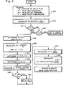
- FIG. 5 shows a flow chart of a program which may be implemented on the controller 120 for calculating the flow rate of liquid in the valve body 4.
- the first step after the start, is to measure the position of the valve plug (piston), and the valve inlet pressure, valve outlet pressure, and temperature of the fluid flowing in the valve for given positions of the valve plug (box 304). These measurements are supplied to the valve controller which stores the measurements for subsequent processing.
- the pressure drop ⁇ P v across the valve body for various valve plug positions is calculated in accordance with the formula of box 308. This pressure drop is corrected for ISA standards since subsequent calculations in arriving at the flow rate are all keyed to these ISA standards.
- the correction formula is shown in box 312, where a and b are empirically determined constants for various positions of the valve plug for the particular valve in question typically done to compensate for change in pressure readings.
- the vapor pressure P v of the liquid is calculated in accordance with the formula shown in box 316, where A, B and C are Antoines coefficients for the liquid in question.
- the liquid pressure ratio factor F f is then calculated in accordance with the formula given in box 320, where P c is the critical pressure for the particular liquid flowing through the valve.
- the flow coefficient C v and liquid pressure recovery coefficient F L for the valve are determined from predetermined, stored tables for the particular valve and for various positions of the valve plug.
- the valve is checked to determine if it is choked (cavitating) and this is done by first calculating the pressure drop across the valve for the choked condition ⁇ P(choked) in accordance with the formula shown in box 328.
- the specific gravity G f of the liquid is next calculated pursuant to the formula in box 332, where GFB, T c and T B are known constants for the particular liquid in question.
- box 336 a determination is made as to whether or not the pressure drop calculated in box 312 is greater than the pressure drop for a choked valve, calculated in box 328, and if it is, the process moves to box 340, otherwise the process moves to box 344.
- the flow rate q is calculated using formulas shown in the boxes to give the desired current measure of flow rate.
- the calculated flow rate may either be used to apprise the user by way of a visual display as to the present flow rate of fluid in the valve, or to provide an indication to the controller as to which direction the valve plug must be moved to change the flow rate and thus bring it closer to a predetermined desired flow rate value.
- the controller would develop the appropriate signal for supply to the valve positioner to cause the valve positioner to change the position of the valve plug, after which measurements and calculations to obtain the flow rate would again be made. This process would be repeated until the desired flow rate were achieved.
- FIG. 6 shows a flow diagram for calculating flow rate of a gas in the valve of FIGS. 1 and 2.
- the first step after starting is to measure the position of the valve plug, and the valve inlet pressure, valve outlet pressure and valve fluid temperature as indicated in box 404.
- the vapor pressure of the gas P v is then calculated (box 408) using a formula already discussed.
- a determination is then made as to whether the measured temperature T is greater than the critical absolute temperature T c (for the particular gas flowing through the valve) as indicated in box 412. If it is, the process moves to box 416; otherwise the process moves to box 420.
- a determination is made as to whether the valve inlet pressure P i is greater than or equal to the vapor pressure P v and if it is, the process is stopped since the fluid flowing in the valve may be a liquid rather than a gas.
- valve inlet pressure calibrated to ISA standards and the valve outlet pressure, also calibrated to ISA standards, are determined by table lookup which would have been earlier determined by experimental testing and stored in the controller.
- the next step in the process is to calculate P, and T r (box 420) which, along with stored tables, are used to determine the compressibility factor Z of the gas (box 424), where P c is the critical pressure (psia) for the gas.
- P c is the critical pressure (psia) for the gas.
- the flow coefficient C v and gas pressure recovery coefficient X t for various valve positions are determined from predetermined, previously stored tables.
- the ratio of the pressure drop across the valve to the valve inlet pressure is then calculated in box 432, followed by a determination as to whether X is greater than X t (box 436). If it is (meaning that a choked condition exists), X is set equal to X t (box 440), and the process moves to box 444, whereas if it is not, the process moves directly to 444.
- the expansion factor Y is calculated in accordance with the formula given in box 444, where F k equals K/1.40 and K is the ratio of specific heats for the gas in question. Finally, the flow rate q is calculated in box 448 as shown by the formula.
- the controller may either display the calculated rate, use it to adjust the valve plug position to thereby change the flow rate, or both as previously described for the calculation of liquid flow rates.
Abstract
Description
Claims (18)
- A process control valve comprising:a fluid valve body (4) having a fluid flow passage (16) including an inlet (8) for receiving fluid and an outlet (12) for discharging fluid, the fluid flow passage (16) having a generally linear portion at the inlet (8), a generally linear portion at the outlet (12), and a curved portion between the inlet (8) and the outlet (12);a controllable throttling element (28) which is movable to selectively vary the cross-sectional area of flow of at least a portion of the passage (16);actuator means (40) coupled to the valve body (4) and responsive to control signals for selectively moving the throttling element (28);a first pressure sensor (104) disposed in the linear portion at a side of the inlet (8) of the valve body (4) in the fluid flow passage (16), at a place such that a repeatable, continuous pressure measurement can be made, for producing a first signal representing the pressure P1 of the fluid at the inlet (8);a second pressure sensor (108) disposed in the linear portion at a side of the outlet (12) of the valve body (4) in the fluid flow passage (16), at a place such that a repeatable, continuous pressure measurement can be made, for producing a second signal representing the pressure P2 of the fluid at the outlet (12);a cavitation sensor (132) disposed downstream of the throttling element (28) in the valve body (4) for producing a signal representing the cavitation of the fluid occurring in the fluid flow passage (16);a controller (120) for receiving said first and second signals and for developing an output dependent upon the received signals;said controller (120) including:means for determining the fluid pressure drop across the valve body (4) from the first and second signals;means for storing a predetermined fluid pressure drop value;means for comparing the determined fluid pressure drop with the stored fluid pressure drop value and for producing a difference signal whose magnitude represents a difference between the compared values; andmeans for producing control signals for application to the actuator means (40) to cause it to move the throttling element (28) to thereby vary the fluid pressure drop across the valve body (4) to more closely match the stored predetermined fluid pressure drop value and reduce the magnitude of the difference signal.
- The process control valve according to claim 1, characterised in that said controller (120) further includes means for determining Pi(ISA) and Po(ISA) from the first and second signals, where Pi(ISA) and Po(ISA) represent the fluid pressure calibrated to ISA standards at the inlet (8) and outlet (12) of the valve body (4), respectively.
- The process control valve according to claim 1 or 2, characterised in that it further comprises a temperature sensor (124) disposed in the fluid flow passage (16) for producing a third signal representing the temperature T1 of the fluid in the fluid flow passage (16); andthe controller (120) being adapted for receiving said third signal.
- The process control valve according to claim 3, characterised in that said controller (120) comprises a processing means which includes:means for storing a predetermined temperature value;means for comparing the signal representing the temperature T1 for the fluid with the stored temperature value and for producing a difference signal whose magnitude represents the difference between the compared values.
- The process control valve as in claim 1, characterised in that it further comprisesa temperature sensor (124) for producing a third signal representing the temperature T1 of the fluid in the fluid flow passage; anda throttling element position sensor (96) for producing a fourth signal representing the flow capacity Cv of the valve body (4); andwherein said controller further comprises processing means for determining from the first, second and fourth signals the flow rate of the fluid in the passage (16).
- The process control valve as in claim 5, characterised in that said fluid is a liquid having a specific gravity of GF, and wherein said processing means comprises stored program control means for determining the flow rate Q in accordance with
Cv is the flow capacity of the valve body. - The process control valve as in claim 5, characterised in that said fluid is a gas having a molecular weight of M and a ratio of specific heats k, and wherein said processing means comprises a stored program control means for determining the flow rate Q in accordance withg is a scaling constant determined for the valve body;Cv is the flow capacity of the valve body,Y is an expansion factor equal to 1-ΔP/P13FXT, where
Fk = k/1.40, XT is the terminal pressure drop for the valve body, andZ is a compressibility factor of the gas in question determined for a particular T1 and P1. - The process control valve according to any one of claims 5 to 7,
characterised in that said processing means include:means for storing a predetermined flow rate value;means for comparing the predetermined flow rate with the stored flow rate value and for producing a difference signal whose magnitude represents the difference between the compared values. - The process control valve according to claim 1, characterised in that it further comprisesat least one further sensor (124) disposed in the fluid flow passage (16) for producing at least one further signal representing at least one physical parameter of the fluid present in the valve body (14), andthe controller (120) being adapted for receiving said further signals.
- The process control valve according to claim 9, characterised in that said controller (120) further comprises means for producing a visual display of the further signals.
- The process control valve according to claim 10, characterised in that it comprises a position sensing means (96) for producing a position signal representing the position of the throttling element (28) in the valve body (4), and control signal measuring means for producing a status signal representing the magnitude of the control signal delivered to the actuator means (40); andwherein said visual display producing means comprises a display screen; andmeans for producing a selective display on the display screen of visual signatures representing each of the further signals, position signal and status signal.
- The process control valve according to one of the preceding claims, characterised in that the throttling element (28) is a valve plug movable to selectively vary the size of the valve passage through which fluid flows to thereby vary the rate of fluid flow through the valve, the actuator means (40) is a valve actuator responsive to pneumatic control signals Pu, Pd) for developing a pressure to selectively move the valve plug (28), and the control valve further includes a valve positioner (80) responsive to command signals for producing pneumatic control signals from an air supply source (84) for application to the valve actuator (40),and a valve diagnostic system is provided comprising:means for producing signals indicating the position of the valve plug (28);said first pressure sensor (104);said second pressure sensor (108);means for storing said position signals and said inlet P1 and outlet P2 pressure signals; andmeans for displaying representations of the inlet and outlet pressure signals for selected positions of the valve plug (28).
- The process control valve according to claim 12, characterised in that the valve diagnostic system further includes means (124) disposed in a wall of the valve body (4) adjacent the valve passage (16) for producing signals indicating the temperature of fluid in the passage (16);wherein the storing means further includes means for storing temperature indicating signals, andwherein said displaying means (216) further includes means for displaying representations of the temperature indicating signals for selected positions of the valve plug (28).
- The process control valve according to claim 13, characterised in that the valve diagnostic system further includes processing means responsive to said inlet and outlet pressure signals and said position signals for calculating the flow rates of fluid through the valve body (4), wherein said storing means further includes means for storing flow rate calculations and wherein said displaying means (216) further includes means for displaying representations of the flow rate calculations for selected positions of the valve plug (28).
- The process control valve according to one of the claims 12 to 13, characterised in that the valve diagnostic system further includes:means (140, 144) for producing signals Pa indicating the pressure in the valve actuator (40);means for producing signals Ps indicating the pressure of the air supply source (84);means for producing signals Pc indicating the pressure of the pneumatic control signals;means (96, 94) for producing signals P indicating the position of the valve plug (28);wherein said storing means includes means for storing said signals Pa, Ps, Pc and P, andwherein said displaying means (216) includes means for displaying representations of the signals Pa, Ps and Pc for selected positions of the valve plug.
- The process control valve according to claim 15, characterised in that the valve diagnostic system further includes:signal generation means for producing command signals to define positions to which the valve plug (28) is to be moved;wherein said at least one further sensor means further includes means for producing signals Ic indicating the value of the command signals;wherein said storing means further includes means for storing said signals Ic; andwherein said displaying means (216) further includes means for displaying representations of the signals Ic for selected positions of the valve plug.
- The process control valve according to claim 15, characterised in that the valve diagnostic system further includes input means (212) for supplying input signals to the signal generation means to cause the signal generation means to produce command signals which define positions to which the valve plug (28) is to be moved.
- The process control valve according to one of the claims 12 to 17, characterised in that said valve actuator (40) comprises:a double-action piston actuator having a housing (36), a piston (68) moveable up and down in the housing (36) and coupled to the valve plug (28) to move the valve plug;upper inlet means (72) for receiving upper pneumatic control signals to develop an upper pressure (Pu) to cause the piston (68) to move downwardly; anda lower inlet means (76) for receiving lower pneumatic control signals to develop a lower pressure (Pd) to cause the piston (68) to move upwardly;wherein the valve positioner (80) comprises means responsive to said command signals for selectively supplying upper pneumatic control signals to the upper inlet means (72) of the actuator (40) and lower pneumatic control signals to the lower inlet means (76) to thereby control the position of the valve plug (28); andwherein said Pa signal producing means comprises means for producing signals Pu indicating the magnitude of the upper pressure, and signals Pd indicating the magnitude of the lower pressure.
Applications Claiming Priority (2)
| Application Number | Priority Date | Filing Date | Title |
|---|---|---|---|
| US07/533,166 US5251148A (en) | 1990-06-01 | 1990-06-01 | Integrated process control valve |
| US533166 | 1990-06-01 |
Publications (3)
| Publication Number | Publication Date |
|---|---|
| EP0462432A2 EP0462432A2 (en) | 1991-12-27 |
| EP0462432A3 EP0462432A3 (en) | 1992-01-15 |
| EP0462432B1 true EP0462432B1 (en) | 1998-12-09 |
Family
ID=24124774
Family Applications (1)
| Application Number | Title | Priority Date | Filing Date |
|---|---|---|---|
| EP91108859A Expired - Lifetime EP0462432B1 (en) | 1990-06-01 | 1991-05-29 | Integrated process control valve |
Country Status (8)
| Country | Link |
|---|---|
| US (1) | US5251148A (en) |
| EP (1) | EP0462432B1 (en) |
| JP (1) | JP2772159B2 (en) |
| AT (1) | ATE174439T1 (en) |
| AU (1) | AU3776795A (en) |
| BR (1) | BR9102243A (en) |
| CA (1) | CA2043682C (en) |
| DE (1) | DE69130592T2 (en) |
Cited By (4)
| Publication number | Priority date | Publication date | Assignee | Title |
|---|---|---|---|---|
| US8036760B2 (en) | 2005-10-04 | 2011-10-11 | Fisher-Rosemount Systems, Inc. | Method and apparatus for intelligent control and monitoring in a process control system |
| US8046096B2 (en) | 2005-10-04 | 2011-10-25 | Fisher-Rosemount Systems, Inc. | Analytical server integrated in a process control network |
| US8706267B2 (en) | 2005-10-04 | 2014-04-22 | Fisher-Rosemount Systems, Inc. | Process model identification in a process control system |
| US8925576B2 (en) | 2007-12-04 | 2015-01-06 | Apv Rosista Gmbh | Device for actuating a process valve for use in foodstuffs technology |
Families Citing this family (126)
| Publication number | Priority date | Publication date | Assignee | Title |
|---|---|---|---|---|
| EP0495001B1 (en) * | 1989-10-02 | 1999-02-17 | Rosemount Inc. | Field-mounted control unit |
| IT1251941B (en) * | 1991-10-17 | 1995-05-27 | Nuovo Pignone Spa | IMPROVED ACTUATOR CONTROL SYSTEM OF A FLOW REGULATION VALVE. |
| DE9211165U1 (en) * | 1991-11-29 | 1992-10-29 | Arca Regler Gmbh, 4154 Toenisvorst, De | |
| US5549137A (en) * | 1993-08-25 | 1996-08-27 | Rosemount Inc. | Valve positioner with pressure feedback, dynamic correction and diagnostics |
| US5574657A (en) * | 1994-02-08 | 1996-11-12 | Micro-Trak Systems, Inc. | Electronic rate meter controller and method |
| US5669713A (en) * | 1994-09-27 | 1997-09-23 | Rosemount Inc. | Calibration of process control temperature transmitter |
| US5488969A (en) * | 1994-11-04 | 1996-02-06 | Gas Research Institute | Metering valve |
| US5634786A (en) * | 1994-11-30 | 1997-06-03 | North American Manufacturing Company | Integrated fuel/air ratio control system |
| US5966679A (en) * | 1995-10-30 | 1999-10-12 | Fisher Controls International, Inc. | Method of and apparatus for nonobtrusively obtaining on-line measurements of a process control device parameter |
| US5728942A (en) * | 1995-11-28 | 1998-03-17 | Boger; Henry W. | Fluid pressure measuring system for control valves |
| US5902927A (en) | 1995-12-01 | 1999-05-11 | Perception Incorporated | Fluid metering apparatus and method |
| US6076542A (en) * | 1995-12-01 | 2000-06-20 | Perception Incorporated | Fluid metering method |
| DE19612370C1 (en) * | 1996-03-28 | 1997-11-20 | Samson Ag | Flow determining apparatus for process fluid at regulating device |
| US5934302A (en) * | 1996-05-01 | 1999-08-10 | Nemelka; Mark S. | Control valve apparatus and method for regulating fluid flow in fluid-intake machines |
| JP3182717B2 (en) * | 1996-06-06 | 2001-07-03 | 株式会社山武 | Control valve abnormality detection method and detection device |
| US5884894A (en) * | 1996-08-20 | 1999-03-23 | Valtek, Inc. | Inner-loop valve spool positioning control apparatus |
| DE29721502U1 (en) * | 1996-12-21 | 1998-04-23 | Klein Schanzlin & Becker Ag | String control valve |
| EP0858018A1 (en) * | 1997-02-06 | 1998-08-12 | Georg Fischer Rohrleitungssysteme AG | Method and device for flow control of liquids |
| US5913183A (en) * | 1997-04-07 | 1999-06-15 | Taiwan Semiconductor Manufacturing Company, Ltd. | Check device for air activated pressure valve |
| US6272401B1 (en) | 1997-07-23 | 2001-08-07 | Dresser Industries, Inc. | Valve positioner system |
| US5974945A (en) * | 1997-08-14 | 1999-11-02 | Valtek, Inc. | Pneumatic valve positioner with adjustable gain |
| US6035878A (en) * | 1997-09-22 | 2000-03-14 | Fisher Controls International, Inc. | Diagnostic device and method for pressure regulator |
| US6056008A (en) * | 1997-09-22 | 2000-05-02 | Fisher Controls International, Inc. | Intelligent pressure regulator |
| US6466893B1 (en) | 1997-09-29 | 2002-10-15 | Fisher Controls International, Inc. | Statistical determination of estimates of process control loop parameters |
| US6192321B1 (en) * | 1997-09-29 | 2001-02-20 | Fisher Controls International, Inc. | Method of and apparatus for deterministically obtaining measurements |
| US6804618B2 (en) * | 1997-09-29 | 2004-10-12 | Fisher Controls International, Llc | Detection and discrimination of instabilities in process control loops |
| US6244296B1 (en) | 1999-02-23 | 2001-06-12 | Spx Corporation | Position detection for rotary control valves |
| DE19910750A1 (en) * | 1999-03-11 | 2000-09-14 | Andreas Moehlenhoff | Procedure for adjusting a valve |
| EP1088260A1 (en) * | 1999-03-25 | 2001-04-04 | Technology Finance Corporation (Proprietary) Limited | Fluid flow control method and apparatus for filtration system |
| DE19917737A1 (en) * | 1999-04-20 | 2000-11-23 | Arca Regler Gmbh | Regulator has a housing and driving member operated by a setting device |
| US6854478B1 (en) * | 1999-05-18 | 2005-02-15 | Xiangwei Zeng | Fluid-controlled valve for pipeline pig |
| DE19924377B4 (en) * | 1999-05-27 | 2004-12-02 | Siemens Ag | Diagnostic system for a valve actuated by a positioner via a drive |
| US6539315B1 (en) * | 1999-06-29 | 2003-03-25 | Fisher Controls International, Inc. | Regulator flow measurement apparatus |
| US7064671B2 (en) * | 2000-06-23 | 2006-06-20 | Fisher Controls International Llc | Low power regulator system and method |
| US6895351B2 (en) * | 1999-06-29 | 2005-05-17 | Fisher Controls International Llc | Regulator flow measurement apparatus |
| JP2001087698A (en) * | 1999-09-22 | 2001-04-03 | Ishikawajima Harima Heavy Ind Co Ltd | Color deforming apparatus for curtain coater |
| US6357335B1 (en) | 1999-12-23 | 2002-03-19 | Sox Corporation | Pneumatic volume booster for valve positioner |
| US7096093B1 (en) * | 2000-02-14 | 2006-08-22 | Invensys Systems, Inc. | Intelligent valve flow linearization |
| DE10012405A1 (en) * | 2000-03-15 | 2001-09-20 | Mannesmann Rexroth Ag | Hydraulic actuator control for electromechanical and electrohydraulic drives, uses electronic control specifically as freely programmable sequence with numerical- and/or stored program control |
| DE10012409A1 (en) * | 2000-03-15 | 2001-09-20 | Mannesmann Rexroth Ag | Hydraulic actuator control for application with machine tools, has electrically actuated valve provided with pressure sensor for detecting pressure in region of output connection of valve |
| US6742539B2 (en) * | 2000-05-24 | 2004-06-01 | Innovative Controls | Co-axial control valve |
| US7621293B2 (en) * | 2001-04-05 | 2009-11-24 | Fisher Controls International Llc | Versatile emergency shutdown device controller implementing a pneumatic test for a system instrument device |
| US6866061B2 (en) * | 2001-09-24 | 2005-03-15 | Hydrogenics Corporation | Back pressure valve with dynamic pressure control |
| US6725876B2 (en) * | 2001-10-15 | 2004-04-27 | Woodward Governor Company | Control valve with integrated electro-hydraulic actuator |
| DE50108787D1 (en) * | 2001-11-23 | 2006-04-13 | Siemens Ag | Method for continuously controlling a position of a control valve |
| US6902620B1 (en) * | 2001-12-19 | 2005-06-07 | Novellus Systems, Inc. | Atomic layer deposition systems and methods |
| US6725167B2 (en) | 2002-01-16 | 2004-04-20 | Fisher Controls International Llc | Flow measurement module and method |
| US6678584B2 (en) * | 2002-05-03 | 2004-01-13 | Fisher Controls International Llc | Method and apparatus for performing diagnostics in a control loop of a control valve |
| US6999853B2 (en) | 2002-05-03 | 2006-02-14 | Fisher Controls International Llc. | Methods and apparatus for operating and performing diagnostics in a control loop of a control valve |
| CN101109470A (en) * | 2002-07-19 | 2008-01-23 | 诚实公司 | Liquid flow controller and precision dispense apparatus and system |
| DE10238963A1 (en) * | 2002-08-20 | 2004-03-04 | Honeywell Ag | Valve in particular line valve |
| DE10257910B3 (en) * | 2002-12-11 | 2004-08-12 | Siemens Ag | Process for monitoring a pipeline and positioner for a control valve |
| US20170138154A1 (en) * | 2003-01-10 | 2017-05-18 | Woodward, Inc. | Wireless Control Valve |
| DE10303889B3 (en) * | 2003-01-30 | 2004-04-08 | Bar Pneumatische Steuerungssysteme Gmbh | Diagnosis method for pneumatic setting drive using monitoring of static pressure component of working space pressure between 2 operating points of setting drive |
| ES2301968T3 (en) * | 2003-02-14 | 2008-07-01 | Dresser, Inc. | METHOD, SYSTEM AND MEMORY MEANS TO EFFECT THE DIAGNOSIS OF A VALVE IN A PRODUCTION LINE. |
| US20040182443A1 (en) * | 2003-03-21 | 2004-09-23 | Douglas Mclntosh | Dual purpose valve |
| DE20304894U1 (en) * | 2003-03-26 | 2003-07-31 | Buerkert Werke Gmbh & Co | Fluid flow control system, e.g. for regulating the flow speed of transport gas, comprises a valve mounted in a prefabricated unit, with pressure transmitters and electronic controller, for ease of installation |
| US20040216782A1 (en) * | 2003-05-03 | 2004-11-04 | Mares E. Joseph | Gas turbine metering valve |
| US20040261855A1 (en) * | 2003-06-27 | 2004-12-30 | Hart Justin Wade | Pressure regulator with integrated reverse pressure exhaust |
| DE20314772U1 (en) * | 2003-09-22 | 2003-12-04 | Gce-Druva Gmbh & Co. Kg | Gas extraction device, in particular for high-purity gases |
| US20050150552A1 (en) * | 2004-01-06 | 2005-07-14 | Randy Forshey | Device, method, and system for controlling fluid flow |
| US7740024B2 (en) * | 2004-02-12 | 2010-06-22 | Entegris, Inc. | System and method for flow monitoring and control |
| CA2564216C (en) * | 2004-05-14 | 2011-03-29 | Exxonmobil Research And Engineering Company | Production and removal of free-flowing coke from delayed coker drum |
| US7082842B2 (en) * | 2004-06-25 | 2006-08-01 | Rivatek Incorporated | Software correction method and apparatus for a variable orifice flow meter |
| WO2006004674A2 (en) * | 2004-06-25 | 2006-01-12 | Rivatek Incorporated | Software correction method and apparatus for a variable orifice flow meter |
| US7246941B2 (en) * | 2004-07-23 | 2007-07-24 | Invensys Building Systems | Sensing media temperature in an HVAC valve |
| DE102005018730B4 (en) * | 2005-04-22 | 2008-04-03 | Karl Dungs Gmbh & Co. Kg | Valve arrangement with piezo control |
| US20090078905A1 (en) * | 2005-04-25 | 2009-03-26 | Joseph Peter Marcilese | Versatile valve |
| US20070016333A1 (en) * | 2005-07-12 | 2007-01-18 | Edwards Grant B | Method and apparatus for controlling the valve position of a variable orifice flow meter |
| US7604019B2 (en) * | 2005-07-22 | 2009-10-20 | B/E Intellectual Property | Electromechanical regulator with primary and backup modes of operation for regulating passenger oxygen |
| US7283894B2 (en) | 2006-02-10 | 2007-10-16 | Dresser, Inc. | System and method for fluid regulation |
| US7530278B2 (en) * | 2006-11-02 | 2009-05-12 | Rivatek, Inc. | Fluid flow blender and methods |
| US7539560B2 (en) * | 2007-01-05 | 2009-05-26 | Dresser, Inc. | Control valve and positioner diagnostics |
| DE102007003602B4 (en) * | 2007-01-18 | 2017-11-23 | B/E Aerospace Systems Gmbh | Sauerstoffnotversorgungssystem |
| NO328089B1 (en) * | 2007-09-03 | 2009-11-30 | Weltec As | Tire gas flow controller for a welding apparatus |
| JP2009115271A (en) * | 2007-11-09 | 2009-05-28 | Yamatake Corp | Flow rate measurement valve |
| JP4927683B2 (en) * | 2007-11-09 | 2012-05-09 | 株式会社山武 | Flow control valve |
| US8037894B1 (en) * | 2007-12-27 | 2011-10-18 | Intermolecular, Inc. | Maintaining flow rate of a fluid |
| US8271141B2 (en) * | 2008-06-09 | 2012-09-18 | Ross Operating Valve Company | Control valve system with cycle monitoring, diagnostics and degradation prediction |
| JP2010019644A (en) * | 2008-07-09 | 2010-01-28 | Bridgestone Corp | Cavitation evaluation device and cavitation evaluation method using the same |
| JP5188937B2 (en) * | 2008-11-14 | 2013-04-24 | 株式会社テイエルブイ | Drain trap |
| JP5188938B2 (en) * | 2008-11-14 | 2013-04-24 | 株式会社テイエルブイ | Drain trap |
| KR101177752B1 (en) * | 2009-04-24 | 2012-08-28 | 영도산업 주식회사 | Cylinder valve having stoppers and cylinder valve system |
| CH700991A1 (en) * | 2009-05-13 | 2010-11-15 | Alstom Technology Ltd | Method for operating a gas turbine plant with a compressor station for gaseous fuel. |
| DE102009040397A1 (en) * | 2009-09-07 | 2011-03-17 | Siemens Aktiengesellschaft | Diagnostic system for a valve |
| DE102009058838A1 (en) | 2009-12-18 | 2011-06-22 | BARTEC BENKE GmbH, 21465 | Measuring arrangement for a liquid, in particular for use in a milk receiving arrangement, and method for operating a milk receiving arrangement |
| US8594852B2 (en) * | 2010-02-22 | 2013-11-26 | Eaton Corporation | Device and method for controlling a fluid actuator |
| JP5426452B2 (en) * | 2010-03-30 | 2014-02-26 | アズビル株式会社 | Positioner |
| JP5457249B2 (en) * | 2010-03-30 | 2014-04-02 | アズビル株式会社 | Positioner |
| JP5466068B2 (en) * | 2010-03-31 | 2014-04-09 | アズビル株式会社 | Electro-pneumatic positioner and electro-pneumatic converter |
| US9441453B2 (en) * | 2010-08-04 | 2016-09-13 | Safoco, Inc. | Safety valve control system and method of use |
| DE202010016534U1 (en) | 2010-11-30 | 2012-03-06 | Arca Regler Gmbh | Control valve actuating device |
| DE102011016650A1 (en) * | 2011-04-01 | 2012-10-04 | Südmo Holding GmbH | Device for monitoring and controlling a valve and such a valve |
| US8974606B2 (en) | 2011-05-09 | 2015-03-10 | Intermolecular, Inc. | Ex-situ cleaning assembly |
| JP5843558B2 (en) * | 2011-10-14 | 2016-01-13 | アズビル株式会社 | Positioner |
| CN102563190A (en) * | 2012-02-03 | 2012-07-11 | 深圳乐满油气技术有限公司 | Pneumatic positioning actuator with intermittent gas supply |
| JP2014077517A (en) * | 2012-10-11 | 2014-05-01 | Azbil Corp | Cavitation diagnostic device |
| US9016140B2 (en) * | 2012-11-20 | 2015-04-28 | Fluid Handling Llc | Valve having rotatable valve ball with calibrated orifice and coaxial upstream/downstream ports and angled taps to measure upstream/downstream pressures for flow measurement |
| US10295080B2 (en) | 2012-12-11 | 2019-05-21 | Schneider Electric Buildings, Llc | Fast attachment open end direct mount damper and valve actuator |
| JP6002029B2 (en) * | 2012-12-26 | 2016-10-05 | アズビル株式会社 | Flow rate calculation device and flow rate control device |
| WO2014143922A1 (en) * | 2013-03-15 | 2014-09-18 | Schneider Electric Buildings, Llc | Advanced valve actuator with true flow feedback |
| US9423050B2 (en) * | 2013-04-09 | 2016-08-23 | Fisher Controls International Llc | Intelligent actuator and method of monitoring actuator health and integrity |
| IL227323A (en) * | 2013-07-04 | 2016-06-30 | Israel Radomsky | System for wirelessly monitoring and predicting failures of linear valves |
| US9989162B2 (en) * | 2013-08-27 | 2018-06-05 | Profire Energy, Inc | Dual cartridge temperature control valve |
| GB2520479A (en) * | 2013-11-05 | 2015-05-27 | Score Group Plc | Improvements in or relating to fluid flow devices |
| DK178362B1 (en) * | 2014-04-07 | 2016-01-11 | Agena As | System for control of inlet air |
| JP2016192039A (en) * | 2015-03-31 | 2016-11-10 | アズビル株式会社 | Flow control valve |
| FR3035469B1 (en) * | 2015-04-23 | 2017-05-12 | Snecma | VALVE AND CONTROL METHOD |
| CN104896180A (en) * | 2015-05-27 | 2015-09-09 | 扬中市第一蝶阀厂有限公司 | Novel regulating valve |
| US20170102078A1 (en) * | 2015-10-07 | 2017-04-13 | Zp Interests, Llc | Hydraulic and programmable hydra seal gate valve and remotely operated fracturing stack |
| US10503181B2 (en) * | 2016-01-13 | 2019-12-10 | Honeywell International Inc. | Pressure regulator |
| US10227838B2 (en) | 2016-05-10 | 2019-03-12 | Weatherford Technology Holdings, Llc | Drilling system and method having flow measurement choke |
| DE102016125643B3 (en) * | 2016-12-23 | 2018-06-14 | Samson Aktiengesellschaft | Control and / or control method for an electropneumatic field device |
| US10792697B2 (en) * | 2017-05-17 | 2020-10-06 | Taiwan Semiconductor Manufacturing Company, Ltd. | Drippage prevention system and method of operating same |
| IL256730A (en) * | 2018-01-04 | 2018-02-28 | Ham Let Israel Canada Ltd | Sensing valve |
| ES2786636T3 (en) * | 2018-03-16 | 2020-10-13 | Siemens Ag | Flow measurement in valves with thermal correction |
| DE102018110084A1 (en) * | 2018-04-26 | 2019-10-31 | Fibro Gmbh | diagnostic unit |
| MX2021004078A (en) | 2018-10-12 | 2021-09-14 | Bray Int Inc | Smart valve with integrated electronics. |
| US11624453B2 (en) | 2018-12-06 | 2023-04-11 | Bray International, Inc. | Smart valve adaptor with integrated electronics |
| CA3127477A1 (en) * | 2019-01-25 | 2020-07-30 | Ideation As | Abnormal condition detection of shut down valves and blow down valves |
| KR102154340B1 (en) * | 2019-02-08 | 2020-09-09 | 주식회사 엑스큐시스템 | Pressurized type explosion-proof valve |
| DE102020124541A1 (en) | 2020-09-21 | 2022-03-24 | Woco Industrietechnik Gmbh | Control valve position detection |
| DE102020213974A1 (en) | 2020-11-06 | 2022-05-12 | Festo Se & Co. Kg | Valve drive device, method for operating a valve drive device and process device |
| US20220275963A1 (en) * | 2021-02-26 | 2022-09-01 | Johnson Controls Technology Company | Flowrate determination system and method for a flow control valve |
| US11668618B2 (en) | 2021-09-27 | 2023-06-06 | Flowserve Pte. Ltd. | Apparatus for measuring the pressure and flow rate of a high temperature corrosive liquid |
| WO2024040359A1 (en) * | 2022-08-23 | 2024-02-29 | Gabriel Eliceo Madariaga Elgueta | System and method for measuring fluid flow in pressurised and/or atmospheric systems that uses at least one valve as a sensor element |
Family Cites Families (36)
| Publication number | Priority date | Publication date | Assignee | Title |
|---|---|---|---|---|
| DE1295254B (en) * | 1958-03-03 | 1969-05-14 | Sulzer Ag | Arrangement for controlling the amount of medium flowing through a line with a throttle element per unit of time |
| US3746049A (en) * | 1971-02-05 | 1973-07-17 | Connor J O | A control valve |
| US4121763A (en) * | 1977-07-07 | 1978-10-24 | The Garrett Corporation | Fluid temperature transducer |
| JPS54142017A (en) * | 1978-04-27 | 1979-11-05 | Toshiba Corp | Trend graph display unit |
| JPS5578206U (en) * | 1978-11-20 | 1980-05-29 | ||
| EP0012267B1 (en) * | 1978-12-06 | 1982-07-28 | Yarway Corporation | Thermostatic steam trap and insert assembly usable in a body member to form a thermostatic steam trap |
| US4277832A (en) * | 1979-10-01 | 1981-07-07 | General Electric Company | Fluid flow control system |
| US4333389A (en) * | 1980-01-18 | 1982-06-08 | Tadeusz Budzich | Load responsive fluid control valve |
| GB2077434B (en) * | 1980-05-30 | 1984-04-26 | Millar John | Ascertaining flow rate through valves or pumps |
| JPS57189212A (en) * | 1981-05-15 | 1982-11-20 | Mitsubishi Electric Corp | Monitor device for device operation |
| US4458839A (en) * | 1982-03-03 | 1984-07-10 | Masco Corporation | Thermostatic valve assembly |
| JPS596670U (en) * | 1982-07-06 | 1984-01-17 | タコ株式会社 | Pilot regulator system for multiple control |
| GB2123983B (en) * | 1982-07-15 | 1986-01-08 | Delta Technical Services Ltd | Pressure controllers |
| GB2140871A (en) * | 1983-06-03 | 1984-12-05 | Bowthorpe Hellermann Ltd | Piston and cylinder actuator control |
| JPS6089210A (en) * | 1983-10-21 | 1985-05-20 | Mitsubishi Electric Corp | Plant monitor display method |
| US4580305A (en) * | 1983-12-29 | 1986-04-08 | Milliken Research Corporation | Optimum pressure control |
| JPS6129913A (en) * | 1984-07-19 | 1986-02-12 | Kubota Ltd | Flow controller |
| DE3432494C2 (en) * | 1984-09-04 | 1995-07-27 | Buerkert Gmbh | Control arrangement for controlling the throughput of gas or liquid flows in pipelines |
| JPS6184715A (en) * | 1984-10-02 | 1986-04-30 | Tlv Co Ltd | Automatic setting reducing valve |
| JPH0668698B2 (en) * | 1984-12-07 | 1994-08-31 | 株式会社東芝 | Process status monitor |
| JPS6249418A (en) * | 1985-08-28 | 1987-03-04 | Toyooki Kogyo Co Ltd | Pressure control valve |
| JPH04404Y2 (en) * | 1985-11-19 | 1992-01-08 | ||
| US4643350A (en) * | 1985-12-17 | 1987-02-17 | Whirlpool Corporation | Water temperature sensing and control means for automatic washer |
| GB8620357D0 (en) * | 1986-08-21 | 1986-10-01 | Apv Int Ltd | Flow control valve |
| US4896101A (en) * | 1986-12-03 | 1990-01-23 | Cobb Harold R W | Method for monitoring, recording, and evaluating valve operating trends |
| DE3700898A1 (en) * | 1987-01-14 | 1988-07-28 | Herion Werke Kg | Flow control valve |
| US4761999A (en) * | 1987-02-27 | 1988-08-09 | Crosby Valve & Gage Company | Set pressure verification device and method |
| JP2532920Y2 (en) * | 1987-04-07 | 1997-04-16 | 西部電機 株式会社 | Valve control device with built-in electronic control device |
| US4875623A (en) * | 1987-07-17 | 1989-10-24 | Memrysafe, Inc. | Valve control |
| JPS6484118A (en) * | 1987-09-26 | 1989-03-29 | Yamatake Honeywell Co Ltd | Control valve with flow rate indicator |
| US4879662A (en) * | 1988-03-11 | 1989-11-07 | Sundstrand Corporation | Fluid flow self calibration scheme |
| JPH01292509A (en) * | 1988-05-20 | 1989-11-24 | Chino Corp | Meter display device |
| US5040380A (en) * | 1988-08-04 | 1991-08-20 | Super S.E.E.R. Systems Inc. | Method and apparatus for the sensing of refrigerant temperatures and the control of refrigerant loading |
| US4976144A (en) * | 1988-08-25 | 1990-12-11 | Fisher Controls International, Inc. | Diagnostic apparatus and method for fluid control valves |
| US5014211A (en) * | 1989-06-16 | 1991-05-07 | Diversey Corporation | Microprocessor controlled liquid chemical delivery system and method |
| US5029597A (en) * | 1990-01-22 | 1991-07-09 | Liberty Technology Center, Inc. | Controller for controlling the operation of a motor operated valve combination |
-
1990
- 1990-06-01 US US07/533,166 patent/US5251148A/en not_active Expired - Lifetime
-
1991
- 1991-05-29 AT AT91108859T patent/ATE174439T1/en not_active IP Right Cessation
- 1991-05-29 DE DE69130592T patent/DE69130592T2/en not_active Expired - Lifetime
- 1991-05-29 EP EP91108859A patent/EP0462432B1/en not_active Expired - Lifetime
- 1991-05-31 BR BR919102243A patent/BR9102243A/en not_active IP Right Cessation
- 1991-05-31 JP JP3129433A patent/JP2772159B2/en not_active Expired - Fee Related
- 1991-05-31 CA CA002043682A patent/CA2043682C/en not_active Expired - Fee Related
-
1995
- 1995-11-09 AU AU37767/95A patent/AU3776795A/en not_active Abandoned
Non-Patent Citations (2)
| Title |
|---|
| Installation of Instrumentation and Process Control Systems, Handbook of the Engineering Equipment Users' Association, reprinted 1981, ISBN 0 09 458880 5, pages 28-29 * |
| US Technical Journal "Control Engineering", January 1990, pages 74-75. * |
Cited By (4)
| Publication number | Priority date | Publication date | Assignee | Title |
|---|---|---|---|---|
| US8036760B2 (en) | 2005-10-04 | 2011-10-11 | Fisher-Rosemount Systems, Inc. | Method and apparatus for intelligent control and monitoring in a process control system |
| US8046096B2 (en) | 2005-10-04 | 2011-10-25 | Fisher-Rosemount Systems, Inc. | Analytical server integrated in a process control network |
| US8706267B2 (en) | 2005-10-04 | 2014-04-22 | Fisher-Rosemount Systems, Inc. | Process model identification in a process control system |
| US8925576B2 (en) | 2007-12-04 | 2015-01-06 | Apv Rosista Gmbh | Device for actuating a process valve for use in foodstuffs technology |
Also Published As
| Publication number | Publication date |
|---|---|
| CA2043682A1 (en) | 1991-12-02 |
| AU3776795A (en) | 1996-01-11 |
| JPH04232514A (en) | 1992-08-20 |
| CA2043682C (en) | 2000-12-05 |
| AU653151B2 (en) | 1994-09-22 |
| AU7709691A (en) | 1991-12-05 |
| EP0462432A3 (en) | 1992-01-15 |
| DE69130592D1 (en) | 1999-01-21 |
| EP0462432A2 (en) | 1991-12-27 |
| JP2772159B2 (en) | 1998-07-02 |
| US5251148A (en) | 1993-10-05 |
| DE69130592T2 (en) | 1999-05-06 |
| BR9102243A (en) | 1992-01-07 |
| ATE174439T1 (en) | 1998-12-15 |
Similar Documents
| Publication | Publication Date | Title |
|---|---|---|
| EP0462432B1 (en) | Integrated process control valve | |
| JP4897894B2 (en) | Flow measuring device and method using regulator | |
| US5660198A (en) | Flow compensated pressure control system | |
| US5152309A (en) | Valve control apparatus | |
| US6895351B2 (en) | Regulator flow measurement apparatus | |
| US8744784B2 (en) | Diagnostic mechanism in differential pressure type mass flow controller | |
| JP3943026B2 (en) | Automatic centering magnet assembly for use in linear displacement measuring devices | |
| US4581707A (en) | Microprocessor controlled valve flow indicators | |
| US5684245A (en) | Apparatus for mass flow measurement of a gas | |
| EP0708389A1 (en) | Method and apparatus for detecting a fault of a control valve assembly in a control loop | |
| JP5148634B2 (en) | Diagnosis of valve self-leakage | |
| AU9133998A (en) | Integrated process control valve | |
| JP2637881B2 (en) | Flow measurement device | |
| JPH03210608A (en) | Tank pressure controller | |
| JPH05288588A (en) | Volume and leakage quantity measuring device | |
| JPH10228323A (en) | Pressure reducing valve with flow rate measuring function |
Legal Events
| Date | Code | Title | Description |
|---|---|---|---|
| PUAI | Public reference made under article 153(3) epc to a published international application that has entered the european phase |
Free format text: ORIGINAL CODE: 0009012 |
|
| PUAL | Search report despatched |
Free format text: ORIGINAL CODE: 0009013 |
|
| AK | Designated contracting states |
Kind code of ref document: A2 Designated state(s): AT BE CH DE DK ES FR GB GR IT LI NL SE |
|
| AK | Designated contracting states |
Kind code of ref document: A3 Designated state(s): AT BE CH DE DK ES FR GB GR IT LI NL SE |
|
| 17P | Request for examination filed |
Effective date: 19920708 |
|
| 17Q | First examination report despatched |
Effective date: 19940531 |
|
| GRAG | Despatch of communication of intention to grant |
Free format text: ORIGINAL CODE: EPIDOS AGRA |
|
| GRAG | Despatch of communication of intention to grant |
Free format text: ORIGINAL CODE: EPIDOS AGRA |
|
| GRAH | Despatch of communication of intention to grant a patent |
Free format text: ORIGINAL CODE: EPIDOS IGRA |
|
| GRAH | Despatch of communication of intention to grant a patent |
Free format text: ORIGINAL CODE: EPIDOS IGRA |
|
| GRAA | (expected) grant |
Free format text: ORIGINAL CODE: 0009210 |
|
| AK | Designated contracting states |
Kind code of ref document: B1 Designated state(s): AT BE CH DE DK ES FR GB GR IT LI NL SE |
|
| PG25 | Lapsed in a contracting state [announced via postgrant information from national office to epo] |
Ref country code: CH Free format text: LAPSE BECAUSE OF FAILURE TO SUBMIT A TRANSLATION OF THE DESCRIPTION OR TO PAY THE FEE WITHIN THE PRESCRIBED TIME-LIMIT Effective date: 19981209 Ref country code: LI Free format text: LAPSE BECAUSE OF FAILURE TO SUBMIT A TRANSLATION OF THE DESCRIPTION OR TO PAY THE FEE WITHIN THE PRESCRIBED TIME-LIMIT Effective date: 19981209 Ref country code: GR Free format text: LAPSE BECAUSE OF NON-PAYMENT OF DUE FEES Effective date: 19981209 Ref country code: ES Free format text: THE PATENT HAS BEEN ANNULLED BY A DECISION OF A NATIONAL AUTHORITY Effective date: 19981209 Ref country code: BE Free format text: LAPSE BECAUSE OF FAILURE TO SUBMIT A TRANSLATION OF THE DESCRIPTION OR TO PAY THE FEE WITHIN THE PRESCRIBED TIME-LIMIT Effective date: 19981209 Ref country code: AT Free format text: LAPSE BECAUSE OF FAILURE TO SUBMIT A TRANSLATION OF THE DESCRIPTION OR TO PAY THE FEE WITHIN THE PRESCRIBED TIME-LIMIT Effective date: 19981209 |
|
| REF | Corresponds to: |
Ref document number: 174439 Country of ref document: AT Date of ref document: 19981215 Kind code of ref document: T |
|
| REG | Reference to a national code |
Ref country code: CH Ref legal event code: EP |
|
| REF | Corresponds to: |
Ref document number: 69130592 Country of ref document: DE Date of ref document: 19990121 |
|
| ET | Fr: translation filed | ||
| ITF | It: translation for a ep patent filed |
Owner name: MODIANO & ASSOCIATI S.R.L. |
|
| PG25 | Lapsed in a contracting state [announced via postgrant information from national office to epo] |
Ref country code: DK Free format text: LAPSE BECAUSE OF FAILURE TO SUBMIT A TRANSLATION OF THE DESCRIPTION OR TO PAY THE FEE WITHIN THE PRESCRIBED TIME-LIMIT Effective date: 19990309 Ref country code: SE Free format text: LAPSE BECAUSE OF FAILURE TO SUBMIT A TRANSLATION OF THE DESCRIPTION OR TO PAY THE FEE WITHIN THE PRESCRIBED TIME-LIMIT Effective date: 19990309 |
|
| REG | Reference to a national code |
Ref country code: CH Ref legal event code: PL |
|
| PLBE | No opposition filed within time limit |
Free format text: ORIGINAL CODE: 0009261 |
|
| STAA | Information on the status of an ep patent application or granted ep patent |
Free format text: STATUS: NO OPPOSITION FILED WITHIN TIME LIMIT |
|
| 26N | No opposition filed | ||
| REG | Reference to a national code |
Ref country code: GB Ref legal event code: 732E |
|
| NLS | Nl: assignments of ep-patents |
Owner name: FLOWSERVE FCD CORPORATION |
|
| REG | Reference to a national code |
Ref country code: FR Ref legal event code: TP |
|
| REG | Reference to a national code |
Ref country code: GB Ref legal event code: IF02 |
|
| NLS | Nl: assignments of ep-patents |
Owner name: FLOWSERVE MANAGEMENT COMPANY |
|
| REG | Reference to a national code |
Ref country code: GB Ref legal event code: 732E |
|
| REG | Reference to a national code |
Ref country code: FR Ref legal event code: TP |
|
| PGFP | Annual fee paid to national office [announced via postgrant information from national office to epo] |
Ref country code: NL Payment date: 20040429 Year of fee payment: 14 |
|
| PGFP | Annual fee paid to national office [announced via postgrant information from national office to epo] |
Ref country code: FR Payment date: 20040519 Year of fee payment: 14 |
|
| PG25 | Lapsed in a contracting state [announced via postgrant information from national office to epo] |
Ref country code: IT Free format text: LAPSE BECAUSE OF NON-PAYMENT OF DUE FEES;WARNING: LAPSES OF ITALIAN PATENTS WITH EFFECTIVE DATE BEFORE 2007 MAY HAVE OCCURRED AT ANY TIME BEFORE 2007. THE CORRECT EFFECTIVE DATE MAY BE DIFFERENT FROM THE ONE RECORDED. Effective date: 20050529 |
|
| PG25 | Lapsed in a contracting state [announced via postgrant information from national office to epo] |
Ref country code: NL Free format text: LAPSE BECAUSE OF NON-PAYMENT OF DUE FEES Effective date: 20051201 |
|
| PG25 | Lapsed in a contracting state [announced via postgrant information from national office to epo] |
Ref country code: FR Free format text: LAPSE BECAUSE OF NON-PAYMENT OF DUE FEES Effective date: 20060131 |
|
| NLV4 | Nl: lapsed or anulled due to non-payment of the annual fee |
Effective date: 20051201 |
|
| REG | Reference to a national code |
Ref country code: FR Ref legal event code: ST Effective date: 20060131 |
|
| PGFP | Annual fee paid to national office [announced via postgrant information from national office to epo] |
Ref country code: DE Payment date: 20100527 Year of fee payment: 20 |
|
| PGFP | Annual fee paid to national office [announced via postgrant information from national office to epo] |
Ref country code: GB Payment date: 20100525 Year of fee payment: 20 |
|
| REG | Reference to a national code |
Ref country code: DE Ref legal event code: R071 Ref document number: 69130592 Country of ref document: DE |
|
| REG | Reference to a national code |
Ref country code: GB Ref legal event code: PE20 Expiry date: 20110528 |
|
| PG25 | Lapsed in a contracting state [announced via postgrant information from national office to epo] |
Ref country code: GB Free format text: LAPSE BECAUSE OF EXPIRATION OF PROTECTION Effective date: 20110528 |
|
| PG25 | Lapsed in a contracting state [announced via postgrant information from national office to epo] |
Ref country code: DE Free format text: LAPSE BECAUSE OF EXPIRATION OF PROTECTION Effective date: 20110530 |