EP0466988A2 - Permanent magnet having improved corrosion resistance and method for producing the same - Google Patents
Permanent magnet having improved corrosion resistance and method for producing the same Download PDFInfo
- Publication number
- EP0466988A2 EP0466988A2 EP90313781A EP90313781A EP0466988A2 EP 0466988 A2 EP0466988 A2 EP 0466988A2 EP 90313781 A EP90313781 A EP 90313781A EP 90313781 A EP90313781 A EP 90313781A EP 0466988 A2 EP0466988 A2 EP 0466988A2
- Authority
- EP
- European Patent Office
- Prior art keywords
- nitrogen
- carbon
- oxygen
- weight
- permanent magnet
- Prior art date
- Legal status (The legal status is an assumption and is not a legal conclusion. Google has not performed a legal analysis and makes no representation as to the accuracy of the status listed.)
- Granted
Links
Images


Classifications
-
- H—ELECTRICITY
- H01—ELECTRIC ELEMENTS
- H01F—MAGNETS; INDUCTANCES; TRANSFORMERS; SELECTION OF MATERIALS FOR THEIR MAGNETIC PROPERTIES
- H01F1/00—Magnets or magnetic bodies characterised by the magnetic materials therefor; Selection of materials for their magnetic properties
- H01F1/01—Magnets or magnetic bodies characterised by the magnetic materials therefor; Selection of materials for their magnetic properties of inorganic materials
- H01F1/03—Magnets or magnetic bodies characterised by the magnetic materials therefor; Selection of materials for their magnetic properties of inorganic materials characterised by their coercivity
- H01F1/032—Magnets or magnetic bodies characterised by the magnetic materials therefor; Selection of materials for their magnetic properties of inorganic materials characterised by their coercivity of hard-magnetic materials
- H01F1/04—Magnets or magnetic bodies characterised by the magnetic materials therefor; Selection of materials for their magnetic properties of inorganic materials characterised by their coercivity of hard-magnetic materials metals or alloys
- H01F1/047—Alloys characterised by their composition
- H01F1/053—Alloys characterised by their composition containing rare earth metals
- H01F1/055—Alloys characterised by their composition containing rare earth metals and magnetic transition metals, e.g. SmCo5
- H01F1/057—Alloys characterised by their composition containing rare earth metals and magnetic transition metals, e.g. SmCo5 and IIIa elements, e.g. Nd2Fe14B
- H01F1/0571—Alloys characterised by their composition containing rare earth metals and magnetic transition metals, e.g. SmCo5 and IIIa elements, e.g. Nd2Fe14B in the form of particles, e.g. rapid quenched powders or ribbon flakes
Definitions
- This invention relates to a permanent magnet having improved corrosion resistance and a method for producing the same.
- Metallic platings applied by electro or electroless plating practices, provide platings of nickel, copper, tin and cobalt. These practices have been somewhat successful in improving the corrosion resistance of these magnets. Problems may result with this plating practice from the acidic or alkaline solutions used in the pretreatment employed prior to the plating operation. These solutions may remain in the porous surface of the magnet or may react with neodymium-rich phases thereof to form unstable compounds. These unstable compounds react during or after plating to cause loss of plating adhesion. With metallic platings, it is common for the plating to exhibit microporosity which tends to accelerate reaction of unstable phases. For example, if there is a reactive media, such as a halide, in the environment, such as is the case with salt water, a galvanic reaction may result between the metallic plating and the unstable phases of the magnet.
- a reactive media such as a halide
- a permanent magnet characterised by having improved corrosion resistance, which magnet consists essentially of Nd2-Fe,4.-B with oxygen being equal to or greater than 0.6 weight%, carbon 0.05 to 0.15 weight % and nitrogen 0.15 weight % maximum.
- oxygen may be 0.6 to 1.2 weight %, carbon 0.05 to 0.1 weight % and nitrogen 0.02 to 0.15 or more preferably 0.04 to 0.08 weight %.
- the aforementioned magnet compositions may be heated in an argon atmosphere and thereafter quenched in a nitrogen atmosphere to further improve the corrosion resistance thereof.
- the heating in the argon atmosphere may be conducted at a temperature of about 550°C.
- the permanent magnet alloy from which the magnet samples were produced contained one or more of the rare earth elements, Nd and Dy, in combination with iron and boron.
- the material was produced by vacuum induction melting of a pre-alloyed charge to produce a molten mass of the desired permanent magnet alloy composition.
- the molten mass was either poured into a mold or atomized to form fine powder by the use of argon gas.
- the alloy RNA-1 was atomized with a mixture of argon and nitrogen gas. With the molten material poured into a mold, the resulting solidified ingot casting was crushed and pulverized to form coarse powders. These powders, as well as the atomized powders, were ground to form fine powder by jet milling. The average particle sizes of these milled powders were in the range 1 to 4 microns.
- the oxygen content of the alloys was controlled by introducing a controlled amount of air during jet milling or alternately blending the powders in air after the milling operation.
- the nitrogen content was usually controlled by introducing a controlled amount of nitrogen during jet milling, but nitrogen was also introduced during atomization.
- the latter practice usually produced a high nitrogen content alloy.
- the nitrogen content was controlled by blending low and high nitrogen alloy powders. This practice was used to produce the samples reported in Table 11 hereinafter.
- the carbon content was controlled by introducing a controlled amount of carbon into the alloys during melting and/or by blending high carbon alloy powder and low carbon alloy powder to achieve the desired carbon content.
- the alloy powders were placed in a rubber bag, aligned in a magnetic field and compacted by cold isostatic pressing.
- the specific alloy compositions used in the experimental work reported herein are listed in Table 1.
- the cold pressed compacts were sintered to substantially full theoretical density in a vacuum furnace at a temperature of 1030°C for one hour. A portion of the sintered or sintered plus heat treated magnet was then ground to a desired shape. Some of the ground magnets were further heat treated in various environments at different temperatures, as well as being subjected to surface treatment, such as with chromic acid.
- the samples were tested with respect to corrosion behavior using an autoclave operated at 5-10 psi in a steam environment at a temperature of 110-1150 C for 18, 40 or 96 hours. After autoclave testing, the weight loss of the samples was measured with a balance after removing the corrosion products therefrom. The weight loss per unit area of the sample was plotted as a function of the oxygen, nitrogen or carbon content. The contents of oxygen, nitrogen and carbon in the magnet were analyzed with a Leco oxygen- nitrogen analyzer and carbon-sulfur analyzer. The corrosion product was identified by the use of X-ray diffraction.
- Figures 1-3 and Tables 2-5 report the weight loss for the reported magnet compositions after exposure in an autoclave at 5-10 psi within the temperature range of 110-1150 C for 40 and 96 hours, as a function of the oxygen content.
- the weight loss of the magnet was measured per unit area of the sample during autoclave testing to provide an indication of the corrosion rate of the magnet in the autoclave environment.
- the corrosion rate of the magnet decreases rapidly as the oxygen content increases from 0.2 to about 0.6%, and reaches a minimum when the oxygen content is between 0.6 and 1.0%. With the minimum corrosion rate, the weight loss is less than 1 mg/cm 2 and the corrosion products are barely observable on the surface of the magnet sample after exposure in the autoclave environment for the test period.
- the oxygen content required to achieve the minimum corrosion rate varies depending upon the carbon and nitrogen contents with the corrosion rate decreasing rapidly as the oxygen content increases up to about 0.6%.
- the corrosion rate of the reported alloy also decreases rapidly with oxygen content increases from 0.2 to 0.6% and reaches the minimum at an oxygen content of 1.2%.
- the beneficial affect of oxygen on the corrosion rate shifts from a relatively high oxygen content of about 1.0% to a relatively low oxygen content of about 0.6% as the nitrogen content is varied from a range of 0.014-0.025% to 0.05-0.15% with a carbon content of 0.1 %.
- the corrosion rate decreases as the nitrogen content increases from about 0.02% to between 0.05 to 0.15%.
- This data shows the significance of nitrogen and that nitrogen is beneficial in improving corrosion resistance within the oxygen content limits of the invention, including the preferred oxygen limit of 0.6 to 1.2%.
- Table 5 shows the corrosion rate or the reported alloy composition as a function of the oxygen content. The corrosion rate decreases as the oxygen content increases. It is noted, however, that the corrosion of this alloy is higher than that of the alloy Fe-33.9Nd-1.15B-0.064N-0.14C alloy shown in Table 4 at a similar oxygen content range. This indicates that the corrosion rate is also affected by the carbon content. From these results, it may be seen that the corrosion rate is affected not only by the oxygen content but also by the carbon and nitrogen contents.
- Figures 4-6 and Tables 6-9 show the weight loss of Nd-Fe-B magnets after exposure in an autoclave environment at 5-10 psi at a temperature of 110-115° C as a function of the carbon content.
- the corrosion rate of the magnet decreases rapidly as the carbon content is increased up to about 0.05% and then reaches the minimum corrosion rate at about 0.06% carbon, as shown in Figure 4 and Table 6 and 7.
- the oxygen content is greater than 0.6%
- the nitrogen content is 0.05-0.08% and the carbon content is within the range of 0.06-0.15%
- the corrosion rate is at the minimum level. If the oxygen content is about 0.7%, and the carbon content exceeds 0.15%, the corrosion rate begins to increase. If the oxygen content is greater than 0.8%, then the minimum corrosion rate continues until the carbon content reaches about 0.2%.
- Figure 5 and Table 8 show that the corrosion rates or Nd-Fe-B magnets containing 0.46% oxygen and 0.055% nitrogen decreases to their lowest levels when the carbon content is increased up to about 0.11 % and then rises with further increases in the carbon content.
- Figures 7 and 8 and Tables 10 and 11 show the weight loss of Nd-Fe-B magnets after exposure in an autoclave environment at 5-10 psi at a temperature of 110-115 C as a function of the nitrogen content.
- RNA-1 contains a high nitrogen content (0.4%)
- a low nitrogen content alloy powder (Alloy 3) was blended in a proper ratio to control the nitrogen content of the alloy.
- the corrosion rate of low carbon content alloys increases slowly up to 0.1% nitrogen and then increases with further increases in the nitrogen content. Therefore, a high nitrogen content exceeding 0.15% nitrogen is detrimental to the corrosion resistance of low carbon Nd-Fe-B magnets with nitrogen contents being beneficial within the range of 0.05-0.15% with carbon contents within the range of the invention.
- This data indicates that the carbon and nitrogen contents may adversely affect the corrosion resistance imparted by each if they are not each within the limits of the invention.
- magnets heat treated in an argon atmosphere followed by nitrogen quenching exhibit a corrosion rate much lower than untreated magnets. This indicates that the corrosion resistance can be improved by this heat treatment but that the corrosion resistance cannot be improved to the extent achieved within the oxygen, carbon and nitrogen limits in accordance with the invention.
- the improvement in corrosion resistance achieved through this heat treatment may result from the modification of the magnet surface by forming a protective layer thereon.
- Tables 12, 13 and 14 show the weight loss of various Nd-Fe-B magnets after autoclave testing, as a function of the surface treatment or heat treatment.
- the magnet heat treated at 550°C in an argon atmosphere followed by nitrogen quenching exhibited a corrosion rate lower than that of the control sample (a ground and untreated magnet), while magnets heat treated at 550 °C in nitrogen or heated at 900 °C in vacuum, argon or nitrogen exhibits corrosion rates higher than that of the control sample.
- Table 13 also shows the weight loss of various magnets after autoclave testing as a function of heat treatment.
- heat treatment at 550°C in argon followed by a nitrogen quench substantially reduces the corrosion rate from that of the control sample, while heat treatment at 550 °C in nitrogen and argon followed by nitrogen quenching increases the corrosion rate.
- preheating the sample at 200° C in air or nitrogen increases the corrosion rate over that of the control sample.
- the magnet heat treated at 550 °C in argon followed by a nitrogen quench exhibits a further decrease in the corrosion rate after heating at 200° C in air. Improved corrosion resistance is also achieved by heat treating in vacuum at 550° C followed by argon quenching.
- a heat treatment in a vacuum at 550 °C or 900°C substantially reduces the corrosion rate from the control sample, while heat treatments at 550° C in nitrogen or oxygen containing environments or in argon followed by air quenching increases the corrosion rate significantly. Heat treatment at 550° C under argon slightly improves the corrosion resistance.
- Table 15 shows those phases identified by X-ray diffraction formed on the surface of the magnets after various heat treatments.
- Table 16, 17 and 18 show magnetic properties of various Nd-Fe-B magnets as a function of the carbon, nitrogen and oxygen contents.
- the magnetic properties do not change significantly.
- the nitrogen content is relatively low (less than 0.08%)
- the magnetic properties do not change significantly.
- the nitrogen content is high (greater than 0.15%) it forms NdN by consuming the neodymium-rich phase, which deteriorates the magnetic properties, densification and corrosion resistance.
- the corrosion rate of the magnets decreases with increasing oxygen content and reaches a minimum with an oxygen content within the range of 0.6 to 1.2% with the maximum carbon content being 0.15%.
- the effect of oxygen on corrosion resistance is dependent upon the carbon and nitrogen contents, which must be maintained within the limits of the invention.
- the corrosion resistance is also improved with proper heat treatment to form a protective oxidation resistant layer on the magnet surface.
- the magnetic properties also vary with the oxygen, carbon and nitrogen contents.
Abstract
Description
- This invention relates to a permanent magnet having improved corrosion resistance and a method for producing the same.
- It is known to produce permanent magnets of a rare earth element-iron-boron composition to achieve high energy product at a lower cost than samarium cobalt magnets. These magnets do, however, exhibit severe corrosion by oxidation in air, particularly under humid conditions. This results in degradation of the magnetic properties during use of the magnet.
- Efforts have been made to improve the corrosion resistance of those magnets, such as by applying metallic platings thereto, using aluminum-ion vapor deposition coatings, organic resin coatings, synthetic resin coatings, metal-resin double layer coatings, as well as combinations of these coating systems. In addition, chemical surface treatments have been employed with these magnets in an attempt to improve the corrosion resistance thereof.
- Metallic platings, applied by electro or electroless plating practices, provide platings of nickel, copper, tin and cobalt. These practices have been somewhat successful in improving the corrosion resistance of these magnets. Problems may result with this plating practice from the acidic or alkaline solutions used in the pretreatment employed prior to the plating operation. These solutions may remain in the porous surface of the magnet or may react with neodymium-rich phases thereof to form unstable compounds. These unstable compounds react during or after plating to cause loss of plating adhesion. With metallic platings, it is common for the plating to exhibit microporosity which tends to accelerate reaction of unstable phases. For example, if there is a reactive media, such as a halide, in the environment, such as is the case with salt water, a galvanic reaction may result between the metallic plating and the unstable phases of the magnet.
- With aluminum-ion vapor deposition no pretreatment is required and thus the problems of metallic platings in this regard are avoided. Coatings of this type,however, are characterized by significant microporosity because of the nonuniform deposition of the coating on the surface of the magnet. In addition, this practice is not amenable to mass production processes and thus is too expensive for commercial application.
- The use of resin coatings suffer from poor adhesion to result in the gradual removal of the coating followed by oxidation of the magnet surface at the removed coating portion thereof.
- Metallic-resin double layered coatings if not applied in a continuous fashion result in accelerated, spreading corrosion from any areas of coating discontinuity.
- Chemical surface treatments, including chromic acid, hydrofluoric acid, oxalic acid or phosphate treatments, all suffer from the disadvantage of requiring expensive equipment to comply with environmental regulations. Consequently, these practices are not commercially feasible from the cost standpoint.
- All of the conventional methods for improving the corrosion resistance of permanent magnets of this type suffer from the same deficiency in that the corrosion protection is obtained by a surface treatment of the magnet. Accordingly, the magnet per se is not stabilized with respect to corrosion by any of these surface-treatment practices.
- It is known to vary the composition of the magnet to improve the corrosion resistance thereof. Alloy modifications of this type are disclosed in Narasimhan et al., U.S. Patent No. 4,588,439 wherein an oxygen addition is added to improve corrosion resistance by reducing the disintegration of the magnet in humid high-temperature conditions. A. Kim, and J. Jacobson: 1 EEE Trans on Mag. Mag-23, No. 5, 1987 disclose the addition of aluminum and dysprosium or dysprosium oxide for this purpose. This publication also recognizes that chlorine contamination of the magnet results in deterioration of the corrosion resistance both in humid and in dry air at elevated temperature. Sagawa et al., Japanese Patent No. 63-38555, 1986 disclose the addition of cobalt and aluminum to improve corrosion resistance. These alloying additions are combined with reduced carbon and oxygen contents. Takeshita, and Watanabe: Proceedings of 10th Int'I Workshop on RE magnets and their application (I), Kyoto, Japan, 1989 disclose the addition of oxides of chromium, yttrium, vanadium and aluminum for purposes of corrosion resistance in these alloys. H. Nakamura, A. Fukumo and Yoneyaaama: Proceedings of 10th Int'I Workshop on RE Magnets and Their Application (II) Kyoto, Japan, 1989, discloses the substitution of a portion of iron with cobalt and zirconium for this purpose. A. Hasabe, E. Otsuki and Y. Umetsu: Proceedings of the 10th Int'I Workshop on RE Magnets and their Application (II),
- Kyoto, Japan 1989, disclose various anodic polarization techniques for improving corrosion resistance.
- All of these practices may result in improved corrosion resistance but otherwise provide problems, such as increased cost or degradation of magnetic properties. For example, the addition of cobalt increases the Curie temperature but causes a decrease in coercive force. The addition of the aforementioned oxides degrades the energy product of the magnets.
- It is accordingly a primary object of the present invention to provide a permanent magnet and a method for producing the same wherein improved corrosion resistance may be achieved while minimizing adverse effects, such as degradation of the magnetic properties and increased cost.
- In accordance with one aspect of the invention there is provided a permanent magnet characterised by having improved corrosion resistance, which magnet consists essentially of Nd2-Fe,4.-B with oxygen being equal to or greater than 0.6 weight%, carbon 0.05 to 0.15 weight % and nitrogen 0.15 weight % maximum. Preferably, oxygen may be 0.6 to 1.2 weight %, carbon 0.05 to 0.1 weight % and nitrogen 0.02 to 0.15 or more preferably 0.04 to 0.08 weight %.
- In accordance with the method of the invention the aforementioned magnet compositions may be heated in an argon atmosphere and thereafter quenched in a nitrogen atmosphere to further improve the corrosion resistance thereof. The heating in the argon atmosphere may be conducted at a temperature of about 550°C.
- All percentages are in weight percent unless otherwise indicated.
- Fig. 1 is a graph showing the weight loss of Fe-33.5% Nd-1.1% B-0.1%C-(0.05 to 0.15%)N magnets made from atomized powder after exposure in an autoclave at 5-10 psi for 96 hours, as a function of the oxygen content of the magnet samples;
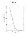
- Fig. 2 is a similar graph showing the weight loss of a magnet of the same composition as Fig. 1, except having 0.014 to 0.025% N, after 96 hours exposure in an autoclave at 5-10 psi, as a function of the oxygen content;
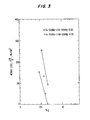
- Fig. 3 in a similar graph showing the weight loss after 96 hours exposure in art autoclave at 5-10 psi as a function of the oxygen content of magnets having the compositions in weight percent listed on this figure;
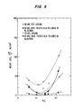
- Fig. 4 is a similar graph showing weight loss after exposure in an autoclave at 5-10 psi as a function of carbon content of magnets having the compositions in weight percent listed on this figure;
- Fig. 5 is a similar graph showing the weight loss of Fe-33.9% Nd-1.15% B-0.46% O-0.055% N magnets after exposure in an autoclave at 5-10 psi as a function of carbon content, exposure time and surface treatment;
- Fig. 6 is a similar graph showing weight loss of Fe-33.9% Nd-1.15%B-0.33% O-0.024% N magnets after autoclave testing for 40 hours at 5-10 psi as a function of the carbon content and surface treatment;
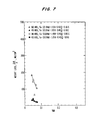
- Fig. 7 is a similar graph showing weight loss of Fe-Nd-B-0.45% O-0.10 to 0.16% C magnets after exposure in an autoclave for 40 hours and 96 hours at 5-10 psi as a function of the nitrogen content; and
- Fig. 8 is a similar graph showing weight loss of Fe-34.2% Nd-1.13% B-0.55% O-0.06% C magnets after exposure in an autoclave for 40 hours at 5-10 psi as a function of nitrogen content.
- To demonstrate the invention permanent magnet alloys and magnets made therefrom were produced by conventional powder metallurgy techniques. The permanent magnet alloy from which the magnet samples were produced contained one or more of the rare earth elements, Nd and Dy, in combination with iron and boron.
- The material was produced by vacuum induction melting of a pre-alloyed charge to produce a molten mass of the desired permanent magnet alloy composition. The molten mass was either poured into a mold or atomized to form fine powder by the use of argon gas. The alloy RNA-1 was atomized with a mixture of argon and nitrogen gas. With the molten material poured into a mold, the resulting solidified ingot casting was crushed and pulverized to form coarse powders. These powders, as well as the atomized powders, were ground to form fine powder by jet milling. The average particle sizes of these milled powders were in the
range 1 to 4 microns. - The oxygen content of the alloys was controlled by introducing a controlled amount of air during jet milling or alternately blending the powders in air after the milling operation. The nitrogen content was usually controlled by introducing a controlled amount of nitrogen during jet milling, but nitrogen was also introduced during atomization. The latter practice usually produced a high nitrogen content alloy. With high nitrogen content alloys, the nitrogen content was controlled by blending low and high nitrogen alloy powders. This practice was used to produce the samples reported in Table 11 hereinafter. The carbon content was controlled by introducing a controlled amount of carbon into the alloys during melting and/or by blending high carbon alloy powder and low carbon alloy powder to achieve the desired carbon content.
- The alloy powders were placed in a rubber bag, aligned in a magnetic field and compacted by cold isostatic pressing. The specific alloy compositions used in the experimental work reported herein are listed in Table 1.

- The cold pressed compacts were sintered to substantially full theoretical density in a vacuum furnace at a temperature of 1030°C for one hour. A portion of the sintered or sintered plus heat treated magnet was then ground to a desired shape. Some of the ground magnets were further heat treated in various environments at different temperatures, as well as being subjected to surface treatment, such as with chromic acid.
- The samples were tested with respect to corrosion behavior using an autoclave operated at 5-10 psi in a steam environment at a temperature of 110-1150 C for 18, 40 or 96 hours. After autoclave testing, the weight loss of the samples was measured with a balance after removing the corrosion products therefrom. The weight loss per unit area of the sample was plotted as a function of the oxygen, nitrogen or carbon content. The contents of oxygen, nitrogen and carbon in the magnet were analyzed with a Leco oxygen- nitrogen analyzer and carbon-sulfur analyzer. The corrosion product was identified by the use of X-ray diffraction.
- It has been determined from the work reported herein that the corrosion rate of Nd-Fe-B magnets is affected by the oxygen, carbon and nitrogen contents of the magnet alloy composition and the heat treatment cycle of the magnet.
- Figures 1-3 and Tables 2-5 report the weight loss for the reported magnet compositions after exposure in an autoclave at 5-10 psi within the temperature range of 110-1150 C for 40 and 96 hours, as a function of the oxygen content. The weight loss of the magnet was measured per unit area of the sample during autoclave testing to provide an indication of the corrosion rate of the magnet in the autoclave environment. As shown in Figure 1 and Table 2, the corrosion rate of the magnet decreases rapidly as the oxygen content increases from 0.2 to about 0.6%, and reaches a minimum when the oxygen content is between 0.6 and 1.0%. With the minimum corrosion rate, the weight loss is less than 1 mg/cm2 and the corrosion products are barely observable on the surface of the magnet sample after exposure in the autoclave environment for the test period. The oxygen content required to achieve the minimum corrosion rate varies depending upon the carbon and nitrogen contents with the corrosion rate decreasing rapidly as the oxygen content increases up to about 0.6%. As shown in Figure 2 and Table 3, the corrosion rate of the reported alloy also decreases rapidly with oxygen content increases from 0.2 to 0.6% and reaches the minimum at an oxygen content of 1.2%. In this regard as may be seen from Figures 1 and 2, the beneficial affect of oxygen on the corrosion rate shifts from a relatively high oxygen content of about 1.0% to a relatively low oxygen content of about 0.6% as the nitrogen content is varied from a range of 0.014-0.025% to 0.05-0.15% with a carbon content of 0.1 %. Hence, at these oxygen and carbon contents, the corrosion rate decreases as the nitrogen content increases from about 0.02% to between 0.05 to 0.15%. This data shows the significance of nitrogen and that nitrogen is beneficial in improving corrosion resistance within the oxygen content limits of the invention, including the preferred oxygen limit of 0.6 to 1.2%.
-


- The corrosion rates of the identical alloy composition used in obtaining the data reported in Figures 1 and 2 except with varying nitrogen contents were compared as a function of the oxygen content. As shown in Figure 3 and Table 4, the corrosion rates of both magnets having low nitrogen (0.038%) and with higher nitrogen (0.064%) decreased rapidly as the oxygen content increased. It may be seen, however, that the corrosion rate progresses downwardly as the nitrogen content increases from 0.038 to 0.064% at the reported range of oxygen content with a carbon content of 0.13%.

- Table 5 shows the corrosion rate or the reported alloy composition as a function of the oxygen content. The corrosion rate decreases as the oxygen content increases. It is noted, however, that the corrosion of this alloy is higher than that of the alloy Fe-33.9Nd-1.15B-0.064N-0.14C alloy shown in Table 4 at a similar oxygen content range. This indicates that the corrosion rate is also affected by the carbon content. From these results, it may be seen that the corrosion rate is affected not only by the oxygen content but also by the carbon and nitrogen contents.

- Figures 4-6 and Tables 6-9 show the weight loss of Nd-Fe-B magnets after exposure in an autoclave environment at 5-10 psi at a temperature of 110-115° C as a function of the carbon content.


- As may be seen from this data, when the oxygen content is greater than 0.6% and the nitrogen content is about 0.025%, the corrosion rate of the magnet decreases rapidly as the carbon content is increased up to about 0.05% and then reaches the minimum corrosion rate at about 0.06% carbon, as shown in Figure 4 and Table 6 and 7. When the oxygen content is greater than 0.6%, the nitrogen content is 0.05-0.08% and the carbon content is within the range of 0.06-0.15%, the corrosion rate is at the minimum level. If the oxygen content is about 0.7%, and the carbon content exceeds 0.15%, the corrosion rate begins to increase. If the oxygen content is greater than 0.8%, then the minimum corrosion rate continues until the carbon content reaches about 0.2%. This data indicates that carbon is an important element in affecting the corrosion rate even in the presence of relatively high oxygen contents. The significant carbon content for the minimum corrosion rate is about 0.05%, and the maximum carbon content for the minimum corrosion rate is about 0.15%. Therefore, when the oxygen content is in the range 0.6-1.2%, this carbon range results in the minimum corrosion rate.
- Figure 5 and Table 8 show that the corrosion rates or Nd-Fe-B magnets containing 0.46% oxygen and 0.055% nitrogen decreases to their lowest levels when the carbon content is increased up to about 0.11 % and then rises with further increases in the carbon content.
- It is noted that although the corrosion rate decreases to its lowest level when the carbon content is within the above-stated range of the invention, the corrosion rate is still relatively high with an oxygen content of 0.46%, which is lower than the 0.6% lower limit for oxygen in accordance with the invention. This indicates that carbon reduces the corrosion rate but does not achieve this alone but only in combination with oxygen within the limits of the invention. Therefore, the minimum corrosion rate can be obtained by controlling both oxygen and carbon, as shown in Figure 4.
- Further reduction in the oxygen content as well as in the nitrogen content increases the overall corrosion rate, as shown in Figure 6 and Table 9. The corrosion rate of Nd-Fe-B magnet containing 0.33% oxygen and 0.024% nitrogen decreases to its lowest value when the carbon content is increased up to about 0.1% and then increases with further increases in the carbon content. The corrosion rate of this magnet as a function of the carbon content exhibits a much higher corrosion rate than that of the magnet containing higher oxygen. This indicates that the magnet containing relatively low oxygen is much more easily oxidized. From this data, it was determined that the carbon content to achieve desired low corrosion rates is within the range of 0.05-0.15%.
- Figures 7 and 8 and Tables 10 and 11 show the weight loss of Nd-Fe-B magnets after exposure in an autoclave environment at 5-10 psi at a temperature of 110-115 C as a function of the nitrogen content.


- As shown in Figure 7, when the carbon content is relatively high (0.10-0.16%C), the corrosion rate decreases as the nitrogen content increases from about 0.04 to about 0.07%. Similar behavior was also observed with respect to the data reported in Figures 1 and 2. When the nitrogen content increases from 0.014-0.025% to 0.05-0.15% in the Fe-33.5Nd-1.1B-0.1C alloy, the corrosion rate decreases substantially at a similar oxygen content. When, however, the carbon content is relatively low (about 0.06%), the effect of the nitrogen content on the corrosion rate is adverse. Figure 8 and Table 11 show the weight loss of the reported magnets made from blends of nitrogen atomized powder (RNA-1) and argon atomized powder (Alloy 3), as a function of the nitrogen content. Since the nitrogen atomized powder (RNA-1) contains a high nitrogen content (0.4%), a low nitrogen content alloy powder (Alloy 3) was blended in a proper ratio to control the nitrogen content of the alloy. As shown in Figure 8, the corrosion rate of low carbon content alloys increases slowly up to 0.1% nitrogen and then increases with further increases in the nitrogen content. Therefore, a high nitrogen content exceeding 0.15% nitrogen is detrimental to the corrosion resistance of low carbon Nd-Fe-B magnets with nitrogen contents being beneficial within the range of 0.05-0.15% with carbon contents within the range of the invention. This data indicates that the carbon and nitrogen contents may adversely affect the corrosion resistance imparted by each if they are not each within the limits of the invention. This data also shows that the corrosion rate reaches a minimum even though the nitrogen content is as low as 0.025% when the oxygen and carbon contents are within the limits of the invention, as shown in Table 7 and Figure 4. From these results, the proper nitrogen content for a minimum corrosion rate is 0.15% maximum, preferably 0.02-0.15%, and more preferably 0.04-0.08%.
- Heat treatment in an argon atmosphere followed by a nitrogen quench substantially reduces the corrosion rate, as shown in Figure 8.
- As shown in Figures 5, 6 and 8, magnets heat treated in an argon atmosphere followed by nitrogen quenching exhibit a corrosion rate much lower than untreated magnets. This indicates that the corrosion resistance can be improved by this heat treatment but that the corrosion resistance cannot be improved to the extent achieved within the oxygen, carbon and nitrogen limits in accordance with the invention. The improvement in corrosion resistance achieved through this heat treatment may result from the modification of the magnet surface by forming a protective layer thereon.
- Tables 12, 13 and 14 show the weight loss of various Nd-Fe-B magnets after autoclave testing, as a function of the surface treatment or heat treatment.


- As shown in Table 12, the magnet heat treated at 550°C in an argon atmosphere followed by nitrogen quenching exhibited a corrosion rate lower than that of the control sample (a ground and untreated magnet), while magnets heat treated at 550 °C in nitrogen or heated at 900 °C in vacuum, argon or nitrogen exhibits corrosion rates higher than that of the control sample. This data shown that heat treatments other than at about 550°C in argon followed by nitrogen quenching form a non-protective layer and thus increase the corrosion rate of the magnet. Table 13 also shows the weight loss of various magnets after autoclave testing as a function of heat treatment. As shown in Table 13, heat treatment at 550°C in argon followed by a nitrogen quench substantially reduces the corrosion rate from that of the control sample, while heat treatment at 550 °C in nitrogen and argon followed by nitrogen quenching increases the corrosion rate. As shown in this table, preheating the sample at 200° C in air or nitrogen increases the corrosion rate over that of the control sample. However, the magnet heat treated at 550 °C in argon followed by a nitrogen quench exhibits a further decrease in the corrosion rate after heating at 200° C in air. Improved corrosion resistance is also achieved by heat treating in vacuum at 550° C followed by argon quenching. As shown in Table 14 a heat treatment in a vacuum at 550 °C or 900°C substantially reduces the corrosion rate from the control sample, while heat treatments at 550° C in nitrogen or oxygen containing environments or in argon followed by air quenching increases the corrosion rate significantly. Heat treatment at 550° C under argon slightly improves the corrosion resistance.
- Table 15 shows those phases identified by X-ray diffraction formed on the surface of the magnets after various heat treatments.

- Table 16, 17 and 18 show magnetic properties of various Nd-Fe-B magnets as a function of the carbon, nitrogen and oxygen contents.


- As shown in Table 16 with fixed carbon and nitrogen contents, the higher oxygen content gives slightly higher remanence (Br) and slightly lower intrinsic coercivity (iHC) than at a lower oxygen content. As the carbon content increases from 0.014 to 0.056%, the remanence remains the same and the intrinsic coercivity increases substantially from 11.4 to 13.0 KOe. This indicates that the magnetic properties generally improve as the carbon content increases up to about 0.06%. With higher carbon contents, both remanence and intrinsic coercivity remain the same with carbon content increases from 0.070 to 0.11 % and begin to decrease with further increases in the carbon content, as shown by the data presented in Table 17. It should be noted, however, that the squareness and Hk value decrease as the carbon content increases. An additional example of the effects of high carbon are shown in the data presented in Table 18. Unlike the data presented in Table 17, in the tests reported in this table the intrinsic coercivity of the magnet decreased as the carbon content increased from about 0.06%. The remanence slightly increased up to about 0.1% carbon and then decreased with further increases in the carbon content. The squareness and Hk value also decreased as carbon content increased. These results indicate that the magnetic properties as a function of the carbon content vary depending upon the alloy composition. In general, as the carbon content increases up to about 0.06%, the magnetic properties may improve. When the carbon content increases from 0.06 to about 0.11%, the magnetic properties may remain the same or decrease slightly. Further increases in the carbon content may reduce the magnetic properties substantially. When the nitrogen content is relatively low (less than 0.08%), the magnetic properties do not change significantly. However, if the nitrogen content is high (greater than 0.15%) it forms NdN by consuming the neodymium-rich phase, which deteriorates the magnetic properties, densification and corrosion resistance.
- As may be seen from the data reported and discussed above in accordance with the invention, the corrosion rate of the magnets decreases with increasing oxygen content and reaches a minimum with an oxygen content within the range of 0.6 to 1.2% with the maximum carbon content being 0.15%. The effect of oxygen on corrosion resistance is dependent upon the carbon and nitrogen contents, which must be maintained within the limits of the invention.
- The corrosion resistance is also improved with proper heat treatment to form a protective oxidation resistant layer on the magnet surface.
- The magnetic properties also vary with the oxygen, carbon and nitrogen contents.
Claims (10)
Priority Applications (1)
| Application Number | Priority Date | Filing Date | Title |
|---|---|---|---|
| DE9018099U DE9018099U1 (en) | 1990-04-10 | 1990-12-21 | Permanent magnet with improved corrosion resistance |
Applications Claiming Priority (2)
| Application Number | Priority Date | Filing Date | Title |
|---|---|---|---|
| US07/507,026 US5162064A (en) | 1990-04-10 | 1990-04-10 | Permanent magnet having improved corrosion resistance and method for producing the same |
| US507026 | 1990-04-10 |
Publications (3)
| Publication Number | Publication Date |
|---|---|
| EP0466988A2 true EP0466988A2 (en) | 1992-01-22 |
| EP0466988A3 EP0466988A3 (en) | 1992-06-17 |
| EP0466988B1 EP0466988B1 (en) | 1994-06-08 |
Family
ID=24016980
Family Applications (1)
| Application Number | Title | Priority Date | Filing Date |
|---|---|---|---|
| EP90313781A Expired - Lifetime EP0466988B1 (en) | 1990-04-10 | 1990-12-21 | Permanent magnet having improved corrosion resistance and method for producing the same |
Country Status (7)
| Country | Link |
|---|---|
| US (2) | US5162064A (en) |
| EP (1) | EP0466988B1 (en) |
| JP (1) | JPH04242902A (en) |
| AT (1) | ATE107077T1 (en) |
| CA (1) | CA2031281A1 (en) |
| DE (2) | DE9018099U1 (en) |
| DK (1) | DK0466988T3 (en) |
Cited By (3)
| Publication number | Priority date | Publication date | Assignee | Title |
|---|---|---|---|---|
| US5282904A (en) * | 1990-04-10 | 1994-02-01 | Crucible Materials Corporation | Permanent magnet having improved corrosion resistance and method for producing the same |
| EP1744331A1 (en) * | 2004-03-31 | 2007-01-17 | TDK Corporation | Rare earth magnet and method for manufacturing same |
| CN101615462B (en) * | 2009-05-26 | 2011-08-17 | 安徽大地熊新材料股份有限公司 | Preparation method of trace nitrogen-containing Re-Fe-B permanent magnetic material |
Families Citing this family (24)
| Publication number | Priority date | Publication date | Assignee | Title |
|---|---|---|---|---|
| US5186765A (en) * | 1989-07-31 | 1993-02-16 | Kabushiki Kaisha Toshiba | Cold accumulating material and method of manufacturing the same |
| GB9217760D0 (en) * | 1992-08-21 | 1992-10-07 | Martinex R & D Inc | Permanent manget material containing a rare-earth element,iron,nitrogen & carbon |
| US5454998A (en) * | 1994-02-04 | 1995-10-03 | Ybm Technologies, Inc. | Method for producing permanent magnet |
| US5486240A (en) * | 1994-04-25 | 1996-01-23 | Iowa State University Research Foundation, Inc. | Carbide/nitride grain refined rare earth-iron-boron permanent magnet and method of making |
| US5480471A (en) * | 1994-04-29 | 1996-01-02 | Crucible Materials Corporation | Re-Fe-B magnets and manufacturing method for the same |
| US5858123A (en) * | 1995-07-12 | 1999-01-12 | Hitachi Metals, Ltd. | Rare earth permanent magnet and method for producing the same |
| DE19541948A1 (en) * | 1995-11-10 | 1997-05-15 | Schramberg Magnetfab | Magnetic material and permanent magnet of the NdFeB type |
| US6022424A (en) * | 1996-04-09 | 2000-02-08 | Lockheed Martin Idaho Technologies Company | Atomization methods for forming magnet powders |
| JP3779404B2 (en) * | 1996-12-05 | 2006-05-31 | 株式会社東芝 | Permanent magnet materials, bonded magnets and motors |
| WO1999002337A1 (en) * | 1997-07-11 | 1999-01-21 | Aura Systems, Inc. | High temperature passivation of rare earth magnets |
| US6332933B1 (en) | 1997-10-22 | 2001-12-25 | Santoku Corporation | Iron-rare earth-boron-refractory metal magnetic nanocomposites |
| US6159308A (en) * | 1997-12-12 | 2000-12-12 | Hitachi Metals, Ltd. | Rare earth permanent magnet and production method thereof |
| WO2000003403A1 (en) | 1998-07-13 | 2000-01-20 | Santoku America Inc. | High performance iron-rare earth-boron-refractory-cobalt nanocomposites |
| DE69916764T2 (en) * | 1998-12-15 | 2005-03-31 | Shin-Etsu Chemical Co., Ltd. | Rare earth / iron / boron based alloy for permanent magnet |
| US6261515B1 (en) | 1999-03-01 | 2001-07-17 | Guangzhi Ren | Method for producing rare earth magnet having high magnetic properties |
| US6818041B2 (en) * | 2000-09-18 | 2004-11-16 | Neomax Co., Ltd | Magnetic alloy powder for permanent magnet and method for producing the same |
| AU2003291539A1 (en) * | 2002-11-18 | 2004-06-15 | Iowa State University Research Foundation, Inc. | Permanent magnet alloy with improved high temperature performance |
| US20050062572A1 (en) * | 2003-09-22 | 2005-03-24 | General Electric Company | Permanent magnet alloy for medical imaging system and method of making |
| EP1712652A4 (en) * | 2004-06-22 | 2010-10-13 | Shinetsu Chemical Co | R-fe-b-based rare earth permanent magnet material |
| US20070089806A1 (en) * | 2005-10-21 | 2007-04-26 | Rolf Blank | Powders for rare earth magnets, rare earth magnets and methods for manufacturing the same |
| US8821650B2 (en) * | 2009-08-04 | 2014-09-02 | The Boeing Company | Mechanical improvement of rare earth permanent magnets |
| JP5494056B2 (en) * | 2010-03-16 | 2014-05-14 | Tdk株式会社 | Rare earth sintered magnet, rotating machine and reciprocating motor |
| CN104766717B (en) * | 2014-01-07 | 2018-12-07 | 中国科学院宁波材料技术与工程研究所 | A method of improving sintered Nd-Fe-B permanent magnet magnetic property |
| CN110957094B (en) * | 2019-12-23 | 2022-07-15 | 厦门优星电子科技有限公司 | Sintering method of neodymium iron boron magnet |
Citations (4)
| Publication number | Priority date | Publication date | Assignee | Title |
|---|---|---|---|---|
| JPS62133040A (en) * | 1985-12-05 | 1987-06-16 | Shin Etsu Chem Co Ltd | Rare-earth permanent magnet material |
| JPS62151542A (en) * | 1985-12-25 | 1987-07-06 | S C M:Kk | Improved permanent magnet material |
| EP0289599A1 (en) * | 1986-06-27 | 1988-11-09 | Namiki Precision Jewel Co., Ltd. | Process for producing permanent magnets |
| JPS63301505A (en) * | 1987-06-01 | 1988-12-08 | Hitachi Metals Ltd | R-b-fe sintered magnet |
Family Cites Families (12)
| Publication number | Priority date | Publication date | Assignee | Title |
|---|---|---|---|---|
| DE268977C (en) * | ||||
| EP0153744B1 (en) * | 1984-02-28 | 1990-01-03 | Sumitomo Special Metals Co., Ltd. | Process for producing permanent magnets |
| JPS61208807A (en) * | 1985-03-13 | 1986-09-17 | Hitachi Metals Ltd | Permanent magnet |
| US4588439A (en) * | 1985-05-20 | 1986-05-13 | Crucible Materials Corporation | Oxygen containing permanent magnet alloy |
| JPH07107882B2 (en) * | 1985-09-12 | 1995-11-15 | 日立金属株式会社 | permanent magnet |
| JPS62119903A (en) * | 1985-11-19 | 1987-06-01 | Shin Etsu Chem Co Ltd | Manufacture of rare earth permanent magnet |
| JPS62165305A (en) * | 1986-01-16 | 1987-07-21 | Hitachi Metals Ltd | Permanent magnet of good thermal stability and manufacture thereof |
| EP0255939B1 (en) * | 1986-08-04 | 1993-07-28 | Sumitomo Special Metals Co., Ltd. | Rare earth magnet and rare earth magnet alloy powder having high corrosion resistance |
| JPH0668144B2 (en) * | 1986-08-04 | 1994-08-31 | 住友特殊金属株式会社 | Rare earth magnet material with excellent corrosion resistance |
| DE3637521A1 (en) * | 1986-11-04 | 1988-05-11 | Schramberg Magnetfab | Permanent magnet and process for producing it |
| FR2610411B1 (en) * | 1987-02-04 | 1989-06-09 | Sfim | METHOD AND DEVICE FOR MEASURING THE SPEED IN RELATION TO THE AIR OF A LOW-SPEED HELICOPTER |
| US5162064A (en) * | 1990-04-10 | 1992-11-10 | Crucible Materials Corporation | Permanent magnet having improved corrosion resistance and method for producing the same |
-
1990
- 1990-04-10 US US07/507,026 patent/US5162064A/en not_active Expired - Lifetime
- 1990-11-30 CA CA002031281A patent/CA2031281A1/en not_active Abandoned
- 1990-12-21 AT AT90313781T patent/ATE107077T1/en active
- 1990-12-21 DE DE9018099U patent/DE9018099U1/en not_active Expired - Lifetime
- 1990-12-21 EP EP90313781A patent/EP0466988B1/en not_active Expired - Lifetime
- 1990-12-21 DK DK90313781.8T patent/DK0466988T3/en active
- 1990-12-21 DE DE69009753T patent/DE69009753D1/en not_active Expired - Lifetime
-
1991
- 1991-04-04 JP JP3097944A patent/JPH04242902A/en active Pending
-
1992
- 1992-10-27 US US07/966,855 patent/US5282904A/en not_active Expired - Lifetime
Patent Citations (4)
| Publication number | Priority date | Publication date | Assignee | Title |
|---|---|---|---|---|
| JPS62133040A (en) * | 1985-12-05 | 1987-06-16 | Shin Etsu Chem Co Ltd | Rare-earth permanent magnet material |
| JPS62151542A (en) * | 1985-12-25 | 1987-07-06 | S C M:Kk | Improved permanent magnet material |
| EP0289599A1 (en) * | 1986-06-27 | 1988-11-09 | Namiki Precision Jewel Co., Ltd. | Process for producing permanent magnets |
| JPS63301505A (en) * | 1987-06-01 | 1988-12-08 | Hitachi Metals Ltd | R-b-fe sintered magnet |
Non-Patent Citations (5)
| Title |
|---|
| IEEE TRANSACTIONS ON MAGNETICS. vol. 26, no. 5, September 1990, NEW YORK US pages 1936 - 1938; A.S.KIM ET AL: 'EFFECT OF OXYGEN, CARBON, AND NITROGEN CONTENTS ON THE CORROSION RESISTANCE OF Nd-Fe-B MAGNETS' * |
| PATENT ABSTRACTS OF JAPAN vol. 11, no. 361 (C-459)(2808) 25 November 1987 & JP-62 133 040 ( SHIN ETSU CHEM CO ) 16 June 1987 * |
| PATENT ABSTRACTS OF JAPAN vol. 11, no. 381 (C-464)(2828) 12 December 1987 & JP-62 151 542 ( S C S K.K. ) 6 July 1987 * |
| PATENT ABSTRACTS OF JAPAN vol. 13, no. 139 (E-738)(3487) 6 April 1989 & JP-63 301 505 ( HITACHI METALS LTD ) 8 December 1988 * |
| PATENT ABSTRACTS OF JAPAN vol. 13, no. 139 (E-738)(3487) 6 April 1989IEEE TRANSACTIONS ON MAGNETICS. vol. 26, no. 5, September 1990, NEW YORK USpages 1936 - 1938; A.S.KIM ET AL: 'EFFECT OF OXYGEN, CARBON, AND NITROGENCONTENTS ON THE CORROSION RESISTANCE OF Nd-Fe-B MAGNETS' * |
Cited By (5)
| Publication number | Priority date | Publication date | Assignee | Title |
|---|---|---|---|---|
| US5282904A (en) * | 1990-04-10 | 1994-02-01 | Crucible Materials Corporation | Permanent magnet having improved corrosion resistance and method for producing the same |
| EP1744331A1 (en) * | 2004-03-31 | 2007-01-17 | TDK Corporation | Rare earth magnet and method for manufacturing same |
| EP1744331A4 (en) * | 2004-03-31 | 2010-06-02 | Tdk Corp | Rare earth magnet and method for manufacturing same |
| US9903009B2 (en) | 2004-03-31 | 2018-02-27 | Tdk Corporation | Rare earth magnet and method for manufacturing same |
| CN101615462B (en) * | 2009-05-26 | 2011-08-17 | 安徽大地熊新材料股份有限公司 | Preparation method of trace nitrogen-containing Re-Fe-B permanent magnetic material |
Also Published As
| Publication number | Publication date |
|---|---|
| JPH04242902A (en) | 1992-08-31 |
| US5162064A (en) | 1992-11-10 |
| US5282904A (en) | 1994-02-01 |
| ATE107077T1 (en) | 1994-06-15 |
| EP0466988A3 (en) | 1992-06-17 |
| DE9018099U1 (en) | 1995-06-01 |
| DE69009753D1 (en) | 1994-07-14 |
| EP0466988B1 (en) | 1994-06-08 |
| DK0466988T3 (en) | 1994-07-11 |
| CA2031281A1 (en) | 1991-10-11 |
Similar Documents
| Publication | Publication Date | Title |
|---|---|---|
| EP0466988B1 (en) | Permanent magnet having improved corrosion resistance and method for producing the same | |
| RU2377681C2 (en) | Rare-earth constant magnet | |
| CN104752049A (en) | Process For Preparing Rare Earth Magnets | |
| US5472525A (en) | Nd-Fe-B system permanent magnet | |
| US20110274898A1 (en) | Method for Producing Sintered Magnet and alloy for sintered magnet | |
| US10672545B2 (en) | R-T-B based permanent magnet | |
| EP0249973A1 (en) | Permanent magnetic material and method for producing the same | |
| CA1336866C (en) | Rare earth magnet having excellent corrosion resistance | |
| JP3781095B2 (en) | Method for producing corrosion-resistant rare earth magnet | |
| EP0430198B1 (en) | Rare earth-based permanent magnet having corrosion resistant surface film and method for the preparation thereof | |
| EP0029071B1 (en) | Process for producing permanent magnet alloy | |
| US5114502A (en) | Magnetic materials and process for producing the same | |
| US5069713A (en) | Permanent magnets and method of making | |
| JP3781094B2 (en) | Corrosion resistant rare earth magnet | |
| EP0386286B1 (en) | Rare earth iron-based permanent magnet | |
| US7338566B2 (en) | Alloy for sm-co based magnet, method for production thereof, sintered magnet and bonded magnet | |
| JPH05247601A (en) | Alloy for corrosion resistant permanent magnet and method for producing permanent magnet therefrom | |
| EP1607491B1 (en) | Process for production of a permanent magnet alloy having improved heat resistance | |
| US5266128A (en) | Magnetic materials and process for producing the same | |
| EP1494250B1 (en) | Rare earth sintered magnet and method for production thereof | |
| JPH04354104A (en) | Manufacture of rare earth bond magnet | |
| JPH0525592A (en) | Rare earth magnet material | |
| Maehara et al. | Development of Sm 2 Fe 17 N 3 magnetic powder doped with La, W, and Ti | |
| JPH04365840A (en) | Rare earth magnet material | |
| JPH04318152A (en) | Rare earth magnetic material and its manufacture |
Legal Events
| Date | Code | Title | Description |
|---|---|---|---|
| PUAI | Public reference made under article 153(3) epc to a published international application that has entered the european phase |
Free format text: ORIGINAL CODE: 0009012 |
|
| AK | Designated contracting states |
Kind code of ref document: A2 Designated state(s): AT BE CH DE DK ES FR GB GR IT LI LU NL SE |
|
| RAP1 | Party data changed (applicant data changed or rights of an application transferred) |
Owner name: CRUCIBLE MATERIALS CORPORATION |
|
| PUAL | Search report despatched |
Free format text: ORIGINAL CODE: 0009013 |
|
| AK | Designated contracting states |
Kind code of ref document: A3 Designated state(s): AT BE CH DE DK ES FR GB GR IT LI LU NL SE |
|
| 17P | Request for examination filed |
Effective date: 19920717 |
|
| 17Q | First examination report despatched |
Effective date: 19930405 |
|
| GRAA | (expected) grant |
Free format text: ORIGINAL CODE: 0009210 |
|
| AK | Designated contracting states |
Kind code of ref document: B1 Designated state(s): AT BE CH DE DK ES FR GB GR IT LI LU NL SE |
|
| PG25 | Lapsed in a contracting state [announced via postgrant information from national office to epo] |
Ref country code: IT Free format text: LAPSE BECAUSE OF FAILURE TO SUBMIT A TRANSLATION OF THE DESCRIPTION OR TO PAY THE FEE WITHIN THE PRE;WARNING: LAPSES OF ITALIAN PATENTS WITH EFFECTIVE DATE BEFORE 2007 MAY HAVE OCCURRED AT ANY TIME BEFORE 2007. THE CORRECT EFFECTIVE DATE MAY BE DIFFERENT FROM THE ONE RECORDED.SCRIBED TIME-LIMIT Effective date: 19940608 Ref country code: LI Effective date: 19940608 Ref country code: CH Effective date: 19940608 Ref country code: GR Free format text: LAPSE BECAUSE OF FAILURE TO SUBMIT A TRANSLATION OF THE DESCRIPTION OR TO PAY THE FEE WITHIN THE PRESCRIBED TIME-LIMIT Effective date: 19940608 Ref country code: NL Effective date: 19940608 Ref country code: AT Effective date: 19940608 |
|
| REF | Corresponds to: |
Ref document number: 107077 Country of ref document: AT Date of ref document: 19940615 Kind code of ref document: T |
|
| ET | Fr: translation filed | ||
| REG | Reference to a national code |
Ref country code: DK Ref legal event code: T3 |
|
| REF | Corresponds to: |
Ref document number: 69009753 Country of ref document: DE Date of ref document: 19940714 |
|
| PG25 | Lapsed in a contracting state [announced via postgrant information from national office to epo] |
Ref country code: DE Effective date: 19940909 |
|
| REG | Reference to a national code |
Ref country code: CH Ref legal event code: PL |
|
| PG25 | Lapsed in a contracting state [announced via postgrant information from national office to epo] |
Ref country code: ES Free format text: LAPSE BECAUSE OF FAILURE TO SUBMIT A TRANSLATION OF THE DESCRIPTION OR TO PAY THE FEE WITHIN THE PRESCRIBED TIME-LIMIT Effective date: 19940919 |
|
| NLV1 | Nl: lapsed or annulled due to failure to fulfill the requirements of art. 29p and 29m of the patents act | ||
| PGFP | Annual fee paid to national office [announced via postgrant information from national office to epo] |
Ref country code: LU Payment date: 19941201 Year of fee payment: 5 |
|
| PGFP | Annual fee paid to national office [announced via postgrant information from national office to epo] |
Ref country code: SE Payment date: 19941221 Year of fee payment: 5 |
|
| PGFP | Annual fee paid to national office [announced via postgrant information from national office to epo] |
Ref country code: BE Payment date: 19941222 Year of fee payment: 5 |
|
| PGFP | Annual fee paid to national office [announced via postgrant information from national office to epo] |
Ref country code: ES Payment date: 19941223 Year of fee payment: 5 |
|
| EAL | Se: european patent in force in sweden |
Ref document number: 90313781.8 |
|
| PLBI | Opposition filed |
Free format text: ORIGINAL CODE: 0009260 |
|
| 26 | Opposition filed |
Opponent name: VACUUMSCHMELZE GMBH, HANAU Effective date: 19950213 |
|
| PG25 | Lapsed in a contracting state [announced via postgrant information from national office to epo] |
Ref country code: LU Free format text: LAPSE BECAUSE OF NON-PAYMENT OF DUE FEES Effective date: 19951221 |
|
| PG25 | Lapsed in a contracting state [announced via postgrant information from national office to epo] |
Ref country code: SE Effective date: 19951222 |
|
| PG25 | Lapsed in a contracting state [announced via postgrant information from national office to epo] |
Ref country code: BE Effective date: 19951231 |
|
| BERE | Be: lapsed |
Owner name: CRUCIBLE MATERIALS CORP. Effective date: 19951231 |
|
| PLBQ | Unpublished change to opponent data |
Free format text: ORIGINAL CODE: EPIDOS OPPO |
|
| PLAB | Opposition data, opponent's data or that of the opponent's representative modified |
Free format text: ORIGINAL CODE: 0009299OPPO |
|
| REG | Reference to a national code |
Ref country code: DK Ref legal event code: EGB |
|
| R26 | Opposition filed (corrected) |
Opponent name: VACUUMSCHMELZE GMBH, HANAU Effective date: 19950213 |
|
| REG | Reference to a national code |
Ref country code: DK Ref legal event code: EGE |
|
| PLBL | Opposition procedure terminated |
Free format text: ORIGINAL CODE: EPIDOS OPPC |
|
| PLBQ | Unpublished change to opponent data |
Free format text: ORIGINAL CODE: EPIDOS OPPO |
|
| PLAB | Opposition data, opponent's data or that of the opponent's representative modified |
Free format text: ORIGINAL CODE: 0009299OPPO |
|
| R26 | Opposition filed (corrected) |
Opponent name: VACUUMSCHMELZE GMBH, HANAU Effective date: 19950213 |
|
| RAP2 | Party data changed (patent owner data changed or rights of a patent transferred) |
Owner name: YBM MAGNEX, INC. |
|
| PLBQ | Unpublished change to opponent data |
Free format text: ORIGINAL CODE: EPIDOS OPPO |
|
| PLAB | Opposition data, opponent's data or that of the opponent's representative modified |
Free format text: ORIGINAL CODE: 0009299OPPO |
|
| R26 | Opposition filed (corrected) |
Opponent name: VACUUMSCHMELZE GMBH, HANAU Effective date: 19950213 |
|
| PLBL | Opposition procedure terminated |
Free format text: ORIGINAL CODE: EPIDOS OPPC |
|
| PLBM | Termination of opposition procedure: date of legal effect published |
Free format text: ORIGINAL CODE: 0009276 |
|
| STAA | Information on the status of an ep patent application or granted ep patent |
Free format text: STATUS: OPPOSITION PROCEDURE CLOSED |
|
| 27C | Opposition proceedings terminated |
Effective date: 20000907 |
|
| REG | Reference to a national code |
Ref country code: DK Ref legal event code: EBP |
|
| REG | Reference to a national code |
Ref country code: GB Ref legal event code: IF02 |
|
| PGFP | Annual fee paid to national office [announced via postgrant information from national office to epo] |
Ref country code: DK Payment date: 20021212 Year of fee payment: 13 |
|
| REG | Reference to a national code |
Ref country code: GB Ref legal event code: 732E |
|
| PG25 | Lapsed in a contracting state [announced via postgrant information from national office to epo] |
Ref country code: DK Free format text: LAPSE BECAUSE OF NON-PAYMENT OF DUE FEES Effective date: 20040102 |
|
| REG | Reference to a national code |
Ref country code: GB Ref legal event code: 732E |
|
| REG | Reference to a national code |
Ref country code: FR Ref legal event code: TP |
|
| REG | Reference to a national code |
Ref country code: DK Ref legal event code: EBP |
|
| PGFP | Annual fee paid to national office [announced via postgrant information from national office to epo] |
Ref country code: FR Payment date: 20041208 Year of fee payment: 15 |
|
| PG25 | Lapsed in a contracting state [announced via postgrant information from national office to epo] |
Ref country code: FR Free format text: LAPSE BECAUSE OF NON-PAYMENT OF DUE FEES Effective date: 20060831 |
|
| REG | Reference to a national code |
Ref country code: FR Ref legal event code: ST Effective date: 20060831 |
|
| PGFP | Annual fee paid to national office [announced via postgrant information from national office to epo] |
Ref country code: GB Payment date: 20071220 Year of fee payment: 18 |
|
| GBPC | Gb: european patent ceased through non-payment of renewal fee |
Effective date: 20081221 |
|
| PG25 | Lapsed in a contracting state [announced via postgrant information from national office to epo] |
Ref country code: GB Free format text: LAPSE BECAUSE OF NON-PAYMENT OF DUE FEES Effective date: 20081221 |