EP0469407A2 - Dispersal valve and canister - Google Patents
Dispersal valve and canister Download PDFInfo
- Publication number
- EP0469407A2 EP0469407A2 EP19910112111 EP91112111A EP0469407A2 EP 0469407 A2 EP0469407 A2 EP 0469407A2 EP 19910112111 EP19910112111 EP 19910112111 EP 91112111 A EP91112111 A EP 91112111A EP 0469407 A2 EP0469407 A2 EP 0469407A2
- Authority
- EP
- European Patent Office
- Prior art keywords
- canister
- fluid
- liquid
- dispersant
- housing
- Prior art date
- Legal status (The legal status is an assumption and is not a legal conclusion. Google has not performed a legal analysis and makes no representation as to the accuracy of the status listed.)
- Granted
Links
Images


Classifications
-
- C—CHEMISTRY; METALLURGY
- C02—TREATMENT OF WATER, WASTE WATER, SEWAGE, OR SLUDGE
- C02F—TREATMENT OF WATER, WASTE WATER, SEWAGE, OR SLUDGE
- C02F1/00—Treatment of water, waste water, or sewage
- C02F1/68—Treatment of water, waste water, or sewage by addition of specified substances, e.g. trace elements, for ameliorating potable water
- C02F1/685—Devices for dosing the additives
- C02F1/688—Devices in which the water progressively dissolves a solid compound
-
- B—PERFORMING OPERATIONS; TRANSPORTING
- B01—PHYSICAL OR CHEMICAL PROCESSES OR APPARATUS IN GENERAL
- B01F—MIXING, e.g. DISSOLVING, EMULSIFYING OR DISPERSING
- B01F21/00—Dissolving
- B01F21/20—Dissolving using flow mixing
- B01F21/22—Dissolving using flow mixing using additional holders in conduits, containers or pools for keeping the solid material in place, e.g. supports or receptacles
- B01F21/221—Dissolving using flow mixing using additional holders in conduits, containers or pools for keeping the solid material in place, e.g. supports or receptacles comprising constructions for blocking or redispersing undissolved solids
-
- C—CHEMISTRY; METALLURGY
- C02—TREATMENT OF WATER, WASTE WATER, SEWAGE, OR SLUDGE
- C02F—TREATMENT OF WATER, WASTE WATER, SEWAGE, OR SLUDGE
- C02F2103/00—Nature of the water, waste water, sewage or sludge to be treated
- C02F2103/42—Nature of the water, waste water, sewage or sludge to be treated from bathing facilities, e.g. swimming pools
-
- Y—GENERAL TAGGING OF NEW TECHNOLOGICAL DEVELOPMENTS; GENERAL TAGGING OF CROSS-SECTIONAL TECHNOLOGIES SPANNING OVER SEVERAL SECTIONS OF THE IPC; TECHNICAL SUBJECTS COVERED BY FORMER USPC CROSS-REFERENCE ART COLLECTIONS [XRACs] AND DIGESTS
- Y10—TECHNICAL SUBJECTS COVERED BY FORMER USPC
- Y10T—TECHNICAL SUBJECTS COVERED BY FORMER US CLASSIFICATION
- Y10T137/00—Fluid handling
- Y10T137/4891—With holder for solid, flaky or pulverized material to be dissolved or entrained
Definitions
- This invention relates to dispersal valves and more specifically to improvements to dispersal valves and removable canisters for dispersal valves.
- a valve with a canister for dispersing materials into a liquid is shown in U.S. patent 4,662,387.
- Such dispersal valves are used to disperse a solid dispersant into a liquid. Typical applications are to disperse chlorine or bromine into a water supply to disinfect the water.
- the prior art inline dispersal valve controls the rate of dispersant by controlling the amount of water flowing through a canister in the dispersal valve.
- the canister includes a removable top for inserting additional dispersant material in the canister.
- the present invention is an improvement to the dispersal valve shown in patent 4,662,387 by providing more precise control of the rate of dispersal over an extended period of time as well as providing a visual indication of when the dispersant in the canister is used up.
- U.S. patent 3,258,968 shows a liquid level indicating device that uses a magnetic switch and a float.
- U.S. patent 4,763,685 shows a floating dispersal member that tips over when the dispersant is dissolved.
- U.S. patent 3,915,340 shows an indicator for a dispensing device for a copier that uses a magnetic switch.
- U.S. patent 885,675 shows a liquid level indicator that uses a magnet that rotates a second magnet on the outside of the container.
- a spiral groove in the side of the container and a float coact to causes the internal magnet to rotate the outside magnet to provide an indication of whether the container is full.
- U.S. patent 4,208,376 shows an indicator that is mechanical pushed up to a visible state from a a recess.
- U.S. patent 1,469,065 shows a sight glass to permit a user to observe and indicator in a fertilizer spreader.
- U.S. patent 2,069,179 shows a pointer that follows the level of the liquid in the container.
- Offenlegungsschrift 2210827 shows an indicator that with a pointer that moves in response to the weight on a spring.
- U.S. patent 4,750,512 shows a fertilizer container with the rate of solution dependent on the the water flow.
- U.S. patent 4,662,387 shows an inline dispersal valve with a keyed cannister to disperse material into a liquid.
- the present invention comprise a dispersal valve and canister with the dispersal valve resiliently supporting a loaded canister in the dispersal valve.
- the canister includes a visual indicator to permit a user to determine when the canister needs to be replaced with the canister having an air pocket for retaining at least a portion of the dispersant above the liquid in the dispersal valve so that the amount of dispersant in contact with the liquid remains substantially constant during a substantial portion of the time the dispersal valve is dispersing material into the liquid.
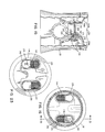
- reference numeral 10 general identifies a dispersal valve for controllable dispersing a solid dispersant such as bromine or chlorine tablets into a liquid.
- Dispersal valve 10 includes a housing 17 having a removable cover 11 fastened thereto by threads or the like. Located on top of cover 11 is an air vent 16 that can be opened to bleed air from dispersal valve 10. Located on top center of cover 11 is a visual indicator means 15 comprising an outer transparent, hollow sight member that permits an observer to peer through the sight member to determine if any visual indication means is present in the sight member.
- Dispersal valve 10 includes a fluid inlet 13 on one side of housing 17 and a fluid outlet 12 located on the opposite side of housing 17.
- a rotary plug 14 permits a user to control the amount of fluid that can be directed through the dispersal valve.
- An example of a dispersal valve with a rotatable plug for controllable directing fluid through the dispersal valve to disperse materials such as bromine and chlorine into swimming pools, hot tubs, spas, and the like is shown in greater detail in U.S. Patent 4,662,387.
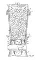
- Fig. 2 shows a partial cross sectional view of a dispersal valve 10 containing a removable, buoyant canister 30 that is filled with solid disk shaped dispersant tablets 9.
- Canister 30 is displaceable upward in response to the dispersing of solid dispersant tablets 9 in canister 30. The upward displacement of canister 30 is used to provide a visual indication that the dispersant in canister 30 has been depleted and that the empty canister 30 should be replaced with a full canister.
- Dispersal valve 10 comprises an interior chamber 45 for holding removable canister 30.
- the lower portion of chamber 45 includes a fluid outlet ports 51 extending upward into a fluid inlet cap 32 which is located in the bottom portion of canister 30.
- Fluid inlet cap 32 includes a grid work to support and prevent dispersant tablets 9 from falling out of canister 30.
- a plurality of openings 31 in fluid cap 32 permits liquid 42 to circulate through and around dispersant tablets 9.
- Located around port 51 is a resilient member 52 comprising a compression spring that provides a normal upward force on an annular lip 32a of canister 30.
- Fig. 2 shows canister 30 filled with dispersant tablets 9 with the weight of canister 30 and dispersant tablets 9 compressing spring 52 downward to hold the inlet cap 32 in fluid communication with outlet port 51.
- a fluid outlet port 33 Located on the side of canister 30 is a fluid outlet port 33 that permits liquid 42 entering canister 30 to be discharged to a fluid inlet port 53 located in the bottom of chamber 45.
- Reference numeral 41 generally identifies the interface between the the air and the liquid 42 in dispersal valve 10. The arrows indicate the general flow of liquid through the interior of valve 10 and canister 30.
- Fig. 2 shows that there are two distinct compartments in canister 30, a lower compartment 30b filled with liquid 42 and solid dispersant tablets 9 and an upper compartment 30a filled with a fluid such as air or a gas and additional dispersant tablets 9.
- the upper compartment comprises an air pocket where air remains trapped since there is no opening in the top portion of canister 30.
- Fig. 2 shows the dispersant valve with a full canister with the dispersant tablets 9 located in both lower compartment 30b and upper air pocket 30a.
- the utilization of a canister that contains an air pocket prevents all of the liquid dissolvable dispersant tablets 9 from being in contact with liquid 42. Consequently, only those tablets 9 that are located in liquid 42 can be dissolved and carried away by liquid 42.
- the present invention by providing an air chamber in the canister 30 can control the rate of dispersant by maintaining the same amount of dispersant tablets in the liquid even though the dispersant tablets are being continually dissolved.
- valve 10 For example if one wanted to use valve 10 to disperse dispersant at a much slower rate one would use a canister with an air pocket to limit the amount of liquid in contact with the dispersant tablets.
- An advantage of the present invention is that not only can the rate of dispersing be slowed down by using a canister with an air pocket but the rate of dispersant remains substantially constant while the dispersant tablets 9 are being dissolved and carried away by liquid 42 since the tablets that are dissolved are being continually being replaced by fresh tablets 9 that fall from upper compartment 30a into lower compartment 30b.
- One of the benefits of the present invention with the use of an air pocket is that it has been found to limit the amount of gas in the canister that results from the dissolution of the solid dispersant. For example, if chlorine tablets are used one will limit the amount of chlorine gas that escapes from the system in comparison to dispersal valves that have open canisters since the canister and its air pocket limit the amount of space for chlorine gas in the dispersal valve. This advantage is particular true in applications where the dispersal valve is located at a lower level than the pool or spa. In these instances the water flows over the top of the canister as the system is shut down but it does not flow into the air pocket.
- valve inlet 13 liquid from valve inlet 13 enters canister 30 through passages 50 in rotary plug 14 and openings 31 in fluid cap 32.
- the liquid flows around the tablets 9 in the lower portion of canister 30 and out through the side opening 33.
- the tablets will either dissolve or erode and be carried away by liquid 42.
- From canister outlet port 33 liquid flows through port 53 and openings 59 in rotary plug 14. Liquid 42 then flows back and into valve outlet port 12 to the pool, spa, or other liquid which requires treatment.
- Fig. 3 shows a top sectional view of the lower portion of valve 10 showing the location of fluid port 55 with spring 52 extending around port 55.
- port 55 is shown as being circular, port 55 could be elliptical or other shape as long as port 55 matches up with the inlet port to canister 30 to thereby direct liquid 42 into canister 30 as the canister moves upward in chamber 45.
- the fluid port 53 shows openings 59 in plug 14 that permit liquid to flow back into the chambers located in the lower portion of valve 10.
- the fluid port 55 shows openings 50 in plug 14 to permit liquid to enter canister 30.
- Fig. 4 shows a side sectional view showing the diversion of a portion of the liquid to the canister and the relative direction of liquid flowing from inlet port 13 to outlet port 12.
- a fluid outlet chamber 12a Located in the lower portion of valve 10 is a fluid outlet chamber 12a and a fluid inlet chamber 13a.
- a venturi ramp 61 Located on the bottom portion of valve 10 is a venturi ramp 61 having a first ramped surface 61 a and a second ramped surface 62b that coacts with extension lip 62 to smoothly and gradually decrease the area for fluid to pass through opening 60.
- the purpose of venturi ramp 60 is to provide a smaller region or opening 60 for the liquid to flow through and consequently increase the velocity of the liquid while decreasing the local pressure on the fluid.
- a venturi ramp 61 is located at the bottom of valve 10 it generally renders the volume of the air in compartment 30a relatively insensitive to changes in downstream pressure located beyond the outlet port 12. Consequently, if the volume of the compressed air in canister 30 remains relatively constant even though the downstream pressure may vary, the level of liquid in the valve remains substantially constant and one can maintain substantially the same amount of tablets in contact with the liquid to thereby maintain a constant rate of dispersant from valve 10.
- Fig. 4 also shows a two way valve 58 that permits liquid in the upper portion of valve 10 to drain into the lower portion when the system is shut down. When the system is pressurized the opposite occurs since valve 58 seals lower chamber 13a from valve chamber 45.
- valve 10 In operation of valve 10 a liquid such as water flows into chamber 13a with a portion of the liquid entering opening 63 and into plug 14 where it flows through port 55. A portion of the liquid continues on through chamber 13a by flowing under lip 62 where the velocity increases and the pressure decreases as the area decreases. As the fluid flows down ramp surface 61 a the area increases and the velocity decreases as the liquid discharges from the discharge side of plug 14. It should be understood that in most applications the downstream pressure remains relatively constant, however in those applications where there may be substantial variation a restricter such as a venturi 61 in valve 10 may be used
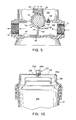
- Fig. 5 shows an alternate embodiment of a dispersal valve where the venturi ramp 61 has been replaced by an upward extending weir 68 that also restricts the area for fluid as it flows from chamber 13a to chamber 12a. In either case the fluid velocity is increased by the decreasing of cross sectional area thereby increasing the velocity of the fluid flowing through the lower portion of valve 10.
- the use of a weir or a venturi ramp the effect is to render the pressure P 3 in the interior of valve 10 and the volume of the air in compartment 30a less sensitive to changes in pressure downstream of valve 10.
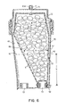
- Fig. 6 shows an alternate embodiment of a canister 70 located in a valve housing 17.
- Canister 70 includes a tapered neck 80 that limits the volume of tablets in contact with the liquid in the canister 70.
- Canister 70 has a top diameter D and a lower cross sectional dimension X located at the liquid level line 41.
- the purpose of having a smaller region at the bottom of a canister is to extend the lower range of dispersing rates of the dispersal valve. That is, a dispersal valve that is normally used to disperse material at a minimum rate through control of the size of the openings in the plug 14 can be adapted to provide even lower more controlled dispersant rates with the present invention.
- the minimum rate of dispersal is determined by the minimum rate of liquid that flows through the valve.
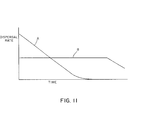
- fig. 11 shows the dispersal rate as a function of time.
- Curve A denotes the dispersal rate with a prior art dispersal valve where the all the dispersant tablets remained in contact with the liquid.
- Curve B illustrates the rate of dispersal with the present invention using a canister where a portion of the tablets are stored in the canister above the liquid.
- a feature of the present invention is not only the ability to scale down the rate of dispersant but also provide for a more uniform dispersion rate of material into the liquid.
- Canister 70 includes a top having a magnet 71 embedded within the central top region of canister 70.
- the axis of magnet 71 is located so that one pole of magnet 71 faces upward and the opposite pole of magnet 71 faces downward.
- Magnet 71 is shown as a permanent part of canister 71.
- Located in the cover 11 is a visual indicating member comprising a transparent sight member 15 that contains a second magnet 15a.
- Magnet 15a is positioned with its poles so that the two magnets repel each other when magnet 71 is brought close to magnet 15a. Consequently, if the magnets 71 and 15a repel one another as canister 70 rises because the dispersant has dissolved it forces magnet 15a upward in sight member 15 thereby visually alerting a user that it is time to replace canister 70.
- Fig. 7 illustrates canister 70 in a nearly empty condition with substantially all of tablets 9 dissolved.
- canister 70 is forced upward by the combination of the buoyant forces and spring 52.
- the magnet 15a is positioned at the top of the sight member thereby providing a visual indicating means to alert a user to the fact that canister 17 needs replacement.
- Fig. 8 shows a further variation of the visual indicating means wherein a canister 100 includes a sight post 109 mounted in a protruding manner at the top of canister 100. Located on the top end of canister 100 are a pair of recesses 105 and 106 with a corresponding hand gripping areas 105a and 106a that permit a user to grasp canister 100 from the top and lift the empty canister from the dispersal valve.
- canister 100 includes an outward extending fluid outlet member 102 that has a cylindrical break line 103 where the the outlet member 102 must be cut off if one wants to insert canister 100 into housing 17. That is, as fig. 9 shows if one attempts to insert canister 100 into housing 17 the canister will not fit. Consequently, one is prevented from inserting the canister into the container unless one is familiar with handling of the dispersant canisters.
- Fig. 10 illustrates how the canister 100 provides a visual indication of the amount of dispersant tablets in the canister.
- Canister 100 includes the post 109 with a colored region 109a that projects partial up into the transparent sight cup located on the top of cover 120. With the transparent sight cover located on the top of canister 100 it is apparent that upward displacement of the canister 100 produces a visual indication of the movement of the canister in housing 17 and consequently of the amount of dispersant remaining in the canister.
- the entire cover 11 can be made from a transparent material with markings on the interior of cover 11. Consequently, upward displacement of canister 100 could be determined by merely observing the vertical position of the canister with regard to the interior markings on cover 11. Also if the canister were made of clear material the user could visually observe the amount of remaining dispersant.
- Fig. 12 shows a top view of a canister 230 having a keyed inlet spout 229 for engaging a port in the dispersal valve.
- Spout 229 has a lip 231 and a tapered neck 232 that fits into a mating opening in the fluid port on the dispersal valve.
- Located inside spout 229 is a screen 235 that has sufficiently small openings so as to prevent granules from falling into the fluid port on the dispersal valve.
- the spout include an extension 242 having an opening 238 for engaging a stud(not shown) in a dispersal valve.
- an extension member 237 having a rectangular opening 239 for engaging a rectangular shaped stud (not shown) on a dispersal valve.
- the combination of keyed opening on the spout for the canister and a stud like key in the dispensing valve prevents one from inserting a cannister into the wrong dispersal valve.
- Fig. 13 shows a partial cross sectional view of a canister and a spout 229.
- container 230 Located in container 230 is a granular dispersant 240.
- the purpose of using a granular dispersant is to enable one to more effectively disperse the dispersant into the liquid as it flows through canister 230 .
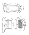
- Fig. 14 shows an alternate embodiment of a canister 130 having a handgrip ridge 131 with a finger recess 132 to permit a user to lift canister 130 out of a dispersal valve.
- Canister 130 comprises a housing having an upper region 133 and a lower region having a first fluid port 134 and a second fluid port 135.
- a cap 136 extends over ports 134 and 135 to seal the canister during storage.
- a break line 138 extends around each of the ports to permit cap 136 to be quickly separated from canister when the canister is in use.
- a mating line 137 identifies where the top half and the lower half of canister have been joined together to form a closed canister.
- Fig. 15 shows a partial sectional view of canister 130 mounted in dispersal valve 10.
- Fig. 15 illustrates the fluid tight sealing relationship of port 134 with an elongated mating extension port 140 located in the bottom of valve 10 through the use of closely mating tapered male and female members.
- the port on the opposite of canister 130 forms a fluid tight sealing relationship with the second mating extension located in the bottom of valve 10.
- the sealing relationship of the ports and extensions can be better seen in fig. 17.
- the purpose of having the ports and extensions forming sealing relationships is that the fluid flowing through my valve must pass through the canister rather than around it and thus avoid contact with the dispersant.
- Canister 130 also includes an elongated cap 142 having a screen 141 on one end and a keyed recess 175 on the other end for matingly engaging a key post 170 in valve 10.
- the key post 170 can be better seen in Figs. 20-22 and comprises a circular base 172 having a circular extension 171 with a male extension 174 comprising the letter K extending upward from base 171 to from a male member for fitting into a female recess.
- Fig. 23 shows the female recess 175 for engaging the male extensions 174 shown in fig. 20.
- a feature of the invention is that the user can make a single all purpose dispersal valves 10 unique to the chemical used in the dispersal valve.
- Fig. 15 and 22 show a cylindrical post 129 extending upward from keypost base 128 in valve 10.
- the recess 173 (fig. 21) in the bottom of keypost 170 forms a mating opening with surface 129s on post 129.
- the surface 173b forms a mating surface with valve surface 106 to permit a manufacturer to instal keypost 170 in a valve through sonic welding or the like.
- the advantage of having a keypost that is installed after the valve is made is that the manufacture can key the valve for the proper canister so only the proper canister is used in the dispersal valve. For example, if one dispersal valve is to be used in a chlorine system that uses only a chlorine canister and another dispersal valve is to be used in a bromine system that uses only a bromine canister the two dispersal valve can be keyed with different keyposts to prevent a user from accidently inserting the bromine canister into the dispersal valve that dispenses chlorine or vice versa.
- my canister allows one to controllable dispense material into a fluid at a substantially constant rate over an extended period of time through the use of an air pocket that limits the amount of fluid in contact with the dispensing material.
- bromine dispersant is formed into a powder. The powder is then formed into granules referred to as granular material.
- the granular material may have 9% of the the particles with a diameter of less than .020 inches with about 91% of the particles having a diameter over .020 inches and generally not greater than about .040 inches in diameter.
- the material in the granular state has been unsuitable for use in canister in dispersal valves since it has been difficult to control the dispersal rate of the granular material into the liquid. Consequently, the granular dispensing material such as chlorine or bromine has been formed into cylindrical tablets that may have a diameter of 1 to 3 inches. These tablets have then been inserted into the canister of the dispersal valve to controllable dispense the material into the liquid in the dispersal valve.
- the present invention provides a canister that can both hold and controllable disperse a dispersant into a liquid while the dispersant is in a granular state.
- Fig.18 shows a portion of the lower region of canister 130 without any dispensing material therein.
- the lower region of canister 130 includes an elongated trough 153 having sides 131 a and 130a that funnel material downward into trough 153 under the force of gravity.
- Canister 130 differs from the other canisters shown in the drawings in that the inlet and the outlet passage for canister 130 are located in the same horizontal plane and at the bottom of though 153.
- Port 134 includes an internal passage 151 for directing liquid inward into a first bottom end of trough 153 and port 135 includes and outlet passage 152 for directing liquid through the opposite bottom end of trough 153.
- the liquid In operation of canister 130 the liquid is directed into trough 153 and flows along the bottom of trough 153 until it discharges through passage 152.
- the air pocket located above trough 153 prevents the liquid from rising in canister 130 and causes the liquid to reach a maximum level indicated by liquid line 155. That is, the level of liquid in trough 153 remains relatively low and is confined to the trough area.
- the trough volume 153 may be only 5% of the total volume of the canister. Consequently, only a very small portion of the dispensing material will remain in contact with the liquid flowing through trough 153.
- a canister containing a dispersant into a dispersal valve that normally may fill with the liquid without having the entire contents of the canister filled with a liquid.
- Fig. 17 illustrates valve 10 and canister 130 in cross section with tablets 9 located in trough 153.
- the height of trough 153 is indicated by h and the liquid level in trough 153 is indicated by L.
- P 2 indicates he pressure at the inlet passage 151
- P 1 indicates the pressure at the outlet 152
- P 3 indicates the pressure in the air pocket 150.
- the tablets in air pocket P 3 remain free of contact with liquid and remain in an undispensed state.
- the tablets 9 located in trough 153 are in contact with the liquid resulting in dispensing of dissolvable or erodible tablets directly into the liquid in proportion to the rate of liquid flowing past the tablets and the amount of tablets in contact with the surface of the tablets.
- a dispersal valve that directs only a portion of the fluid through the trough permits a user to controllable dispense the dispersant in the trough at a substantially constant rate over an extended period of time.
- a canister that continually funnels unspent dispersant into the trough permits one to controllable dispense material at a substantially constant rate for two weeks or longer.
- Fig. 19 shows an alternate embodiment of a canister that is identical to the canister in Fig. 17 except that canister 130 contains a granular material 160 rather than a tabletized or solid material.
- canister 130 contains a granular material 160 rather than a tabletized or solid material.
- bromine and chlorine which was in granular form needed to be tabletized in order to be used in dispersal valves.
- the present invention permits one to use granular material in the canister thus eliminating the step of having to tabletize the material before dispensing.
- the present invention limits the liquid contacting the dispensing material and allows fresh dispensing material to fall into a dispensing trough as the dispensing material is removed from the dispensing trough one can obtain both limited and uniform dispersion rates of the dispensing material over an extended period of time.ln addition the control of the size of the dispensing trough permits one to control the amount of liquid in contact with the dispensing material. The use of an upper region that funnels materials from the upper region to the lower region containing the dispensing trough permits one to continually replenish spent dispensing material.
- a spring support for canister 130 similar to canister spring support 52, can be used to have canister 130 provide a visual indication of the amount of unspent dispersant material remaining in the canister.
- a different sealing relationship between the extension and port would be required to ensure that the fluid is directed through valve 10 as the canister moves up in response to the removal of dispersant.
- my invention includes a pocket with a compressible gas such as air located therein
- a compressible gas such as air located therein
- I provide an automatic method for forcing the liquid away from the dispersant to stop the liberation of dispersant when the line pressure to the valve is shut down. That is, under normally operating pressure in the valve the air in the air pocket compresses to a smaller volume to permit liquid to flow through the valve and the dispersant in the canister.
- the liquid pressure to the line is shutoff the liquid pressure deceases and the air pressure of the compressed air forces the compressed air to expand to its original volume and thus force the liquid in the canister back into the liquid line and out of the canister thus preventing further liberation of dispersant by any residual liquid remaining in contact with the dispersant in the canister.
- my canister provides an effective means for holding and safely disposing of substantially all toxic or noxious dispersant gas remaining in the valve.
- the dispersant was used up one would remove the cover of the valve and place a new dispersant tablet into the valve.
- the valve may contain residual gas from the dispersant even though the dispersant had been used up. For example, if the valve contained chlorine gas once the cover of the valve was removed the chlorine gas could escape and be inhaled by the person attempting to refill the valve. In the present embodiment most of the gas from the dispersant remains in the canister and can be removed with the canister.
Abstract
Description
- This invention relates to dispersal valves and more specifically to improvements to dispersal valves and removable canisters for dispersal valves.
- A valve with a canister for dispersing materials into a liquid is shown in U.S. patent 4,662,387. Such dispersal valves are used to disperse a solid dispersant into a liquid. Typical applications are to disperse chlorine or bromine into a water supply to disinfect the water. In general, the prior art inline dispersal valve controls the rate of dispersant by controlling the amount of water flowing through a canister in the dispersal valve. The canister includes a removable top for inserting additional dispersant material in the canister. The present invention is an improvement to the dispersal valve shown in patent 4,662,387 by providing more precise control of the rate of dispersal over an extended period of time as well as providing a visual indication of when the dispersant in the canister is used up.
- U.S. patent 4,731,036 shows an indicating means using a magnet to indicate the presence of metallic objects in the water
- U.S. patent 3,258,968 shows a liquid level indicating device that uses a magnetic switch and a float.
- U.S. patent 4,552,090 showing a floatable follower with a magnet and a switch to indicate the position of the follower.
- U.S. patent 4,763,685 shows a floating dispersal member that tips over when the dispersant is dissolved.
- U.S. patent 3,915,340 shows an indicator for a dispensing device for a copier that uses a magnetic switch.
- U.S. patent 885,675 shows a liquid level indicator that uses a magnet that rotates a second magnet on the outside of the container. A spiral groove in the side of the container and a float coact to causes the internal magnet to rotate the outside magnet to provide an indication of whether the container is full.
- U.S. patent 4,208,376 shows an indicator that is mechanical pushed up to a visible state from a a recess.
- U.S. patent 1,469,065 shows a sight glass to permit a user to observe and indicator in a fertilizer spreader.
- U.S. patent 2,069,179 shows a pointer that follows the level of the liquid in the container.
- Offenlegungsschrift 2210827 shows an indicator that with a pointer that moves in response to the weight on a spring.
- U.S. patent 4,750,512 shows a fertilizer container with the rate of solution dependent on the the water flow.
- U.S. patent 4,010,708 shows a an indicator for a helicopter blade.
- U.S. patent 4,662,387 shows an inline dispersal valve with a keyed cannister to disperse material into a liquid.
- Briefly, the present invention comprise a dispersal valve and canister with the dispersal valve resiliently supporting a loaded canister in the dispersal valve. The canister includes a visual indicator to permit a user to determine when the canister needs to be replaced with the canister having an air pocket for retaining at least a portion of the dispersant above the liquid in the dispersal valve so that the amount of dispersant in contact with the liquid remains substantially constant during a substantial portion of the time the dispersal valve is dispersing material into the liquid.
- The present invention is described by reference to the drawings in which:
- Fig. 1 is a pictorial view of a dispersal valve;
- Fig. 2 is a partial cut-away view of the dispersal valve and canister;
- Fig. 3 is a top sectional view of the dispersal valve;
- Fig. 4 is a partial sectional view of the bottom of the dispersal valve;
- Fig. 5 is an alternate embodiment partial sectional view of the bottom of the dispersal valve;
- Fig. 6 is a partial cut-away view of an alternate embodiment inside a sectional cut-away dispersal valve;
- Fig. 7 is a partial cut-away view of the emptied canister and the dispersal valve;
- Fig. 8 is a front view of a further alternate embodiment of a canister;
- Fig. 9 is a partial side view of the canister of Fig.8;
- Fig. 10 is a partial side view of the top of the canister of Fig.8 and the top of the dispersal valve;
- Fig. 11 is a graph showing dependent variable, dispersal rate, along the Y-axis versus the independent variable, time, along the X-axis;
- Fig. 12 is a top view of an end spout for a canister;
- Fig. 13 shows a partial cutaway view of a side elevation of a canister containing a granular dispersant.
- Fig. 14 shows a pictorial view of an alternate embodiment of a canister;
- Fig. 15 shows a partial cross sectional view of the canister of Fig. 14 and a dispersal valve;
- Fig. 16 shows a cross sectional view without the dispersant material in the canister taking along lines 16-16 of Fig. 17;
- Fig. 17 shows a cross sectional view of the canister of Fig. 14 and a dispersal valve;
- Fig. 18 shows a partial cross section view of the trough located in the canister of Fig. 15;
- Fig. 19 shows a cross sectional view of the canister of Fig. 14 and a dispersal valve with the canister containing granular material;
- Fig. 20 shows a pictorial view of the keypost used in the dispersal valve;
- Fig. 21 shows a bottom view of the keypost of Fig. 20;
- Fig. 22 shows a sectional view of the keypost of Fig. 20; and
- Fig. 23 shows a bottom view of the canister of Fig. 14.
- Referring to fig. 1
reference numeral 10 general identifies a dispersal valve for controllable dispersing a solid dispersant such as bromine or chlorine tablets into a liquid.Dispersal valve 10 includes ahousing 17 having aremovable cover 11 fastened thereto by threads or the like. Located on top ofcover 11 is anair vent 16 that can be opened to bleed air fromdispersal valve 10. Located on top center ofcover 11 is a visual indicator means 15 comprising an outer transparent, hollow sight member that permits an observer to peer through the sight member to determine if any visual indication means is present in the sight member. -
Dispersal valve 10 includes afluid inlet 13 on one side ofhousing 17 and afluid outlet 12 located on the opposite side ofhousing 17. Arotary plug 14 permits a user to control the amount of fluid that can be directed through the dispersal valve. An example of a dispersal valve with a rotatable plug for controllable directing fluid through the dispersal valve to disperse materials such as bromine and chlorine into swimming pools, hot tubs, spas, and the like is shown in greater detail in U.S. Patent 4,662,387. - Fig. 2 shows a partial cross sectional view of a
dispersal valve 10 containing a removable,buoyant canister 30 that is filled with solid disk shapeddispersant tablets 9. Canister 30 is displaceable upward in response to the dispersing ofsolid dispersant tablets 9 incanister 30. The upward displacement ofcanister 30 is used to provide a visual indication that the dispersant incanister 30 has been depleted and that theempty canister 30 should be replaced with a full canister. -
Dispersal valve 10 comprises aninterior chamber 45 for holdingremovable canister 30. In order to permit removal ofcanister 30 fromhousing 17 there are providethreads 20 onhousing 17 andthreads 21 oncover 11. The thread connection betweenhousing 17 and cover 11 permits the user to removecover 11 and replace an empty canister with a full canister. - The lower portion of
chamber 45 includes afluid outlet ports 51 extending upward into afluid inlet cap 32 which is located in the bottom portion ofcanister 30.Fluid inlet cap 32 includes a grid work to support and preventdispersant tablets 9 from falling out ofcanister 30. A plurality ofopenings 31 influid cap 32 permits liquid 42 to circulate through and arounddispersant tablets 9. Located aroundport 51 is aresilient member 52 comprising a compression spring that provides a normal upward force on anannular lip 32a ofcanister 30. Fig. 2 showscanister 30 filled withdispersant tablets 9 with the weight ofcanister 30 anddispersant tablets 9compressing spring 52 downward to hold theinlet cap 32 in fluid communication withoutlet port 51. - Located on the side of
canister 30 is afluid outlet port 33 that permits liquid 42 enteringcanister 30 to be discharged to afluid inlet port 53 located in the bottom ofchamber 45.Reference numeral 41 generally identifies the interface between the the air and the liquid 42 indispersal valve 10. The arrows indicate the general flow of liquid through the interior ofvalve 10 andcanister 30. - Fig. 2 shows that there are two distinct compartments in
canister 30, alower compartment 30b filled withliquid 42 andsolid dispersant tablets 9 and anupper compartment 30a filled with a fluid such as air or a gas andadditional dispersant tablets 9. The upper compartment comprises an air pocket where air remains trapped since there is no opening in the top portion ofcanister 30. Fig. 2 shows the dispersant valve with a full canister with thedispersant tablets 9 located in bothlower compartment 30b andupper air pocket 30a. In the present invention the utilization of a canister that contains an air pocket prevents all of the liquiddissolvable dispersant tablets 9 from being in contact withliquid 42. Consequently, only thosetablets 9 that are located in liquid 42 can be dissolved and carried away byliquid 42. As thetablets 9 dissolve in the liquid 42 the fresh, undissolved tablets inupper air compartment 30a fall into the liquid 42 incompartment 30b and begin to dissolve. Thus with the present invention and the utilization of an air compartment in the top of the canister, one prevents all of thetablets 9 from simultaneously dissolving or dispersing intoliquid 42. By limiting the amount of tablets in contact withliquid 42 one can control the rate at which thetablets 9 disperse intoliquid 42 since the dissolution rate of dispersant is directly proportional to the amount of dispersant tablets in contact with the liquid. Thus the present invention by providing an air chamber in thecanister 30 can control the rate of dispersant by maintaining the same amount of dispersant tablets in the liquid even though the dispersant tablets are being continually dissolved. One can also disperse material at a lesser rate. For example if one wanted to usevalve 10 to disperse dispersant at a much slower rate one would use a canister with an air pocket to limit the amount of liquid in contact with the dispersant tablets. An advantage of the present invention is that not only can the rate of dispersing be slowed down by using a canister with an air pocket but the rate of dispersant remains substantially constant while thedispersant tablets 9 are being dissolved and carried away byliquid 42 since the tablets that are dissolved are being continually being replaced byfresh tablets 9 that fall fromupper compartment 30a intolower compartment 30b. - One of the benefits of the present invention with the use of an air pocket is that it has been found to limit the amount of gas in the canister that results from the dissolution of the solid dispersant. For example, if chlorine tablets are used one will limit the amount of chlorine gas that escapes from the system in comparison to dispersal valves that have open canisters since the canister and its air pocket limit the amount of space for chlorine gas in the dispersal valve. This advantage is particular true in applications where the dispersal valve is located at a lower level than the pool or spa. In these instances the water flows over the top of the canister as the system is shut down but it does not flow into the air pocket.
- In normal dispensing operation of
dispersal valve 10 liquid fromvalve inlet 13 enterscanister 30 throughpassages 50 inrotary plug 14 andopenings 31 influid cap 32. The liquid flows around thetablets 9 in the lower portion ofcanister 30 and out through theside opening 33. As the liquid flows aroundtablets 9 depending on the type of tablets the tablets will either dissolve or erode and be carried away byliquid 42. Fromcanister outlet port 33 liquid flows throughport 53 andopenings 59 inrotary plug 14.Liquid 42 then flows back and intovalve outlet port 12 to the pool, spa, or other liquid which requires treatment. - Fig. 3 shows a top sectional view of the lower portion of
valve 10 showing the location offluid port 55 withspring 52 extending aroundport 55. Althoughport 55 is shown as being circular,port 55 could be elliptical or other shape as long asport 55 matches up with the inlet port to canister 30 to thereby direct liquid 42 intocanister 30 as the canister moves upward inchamber 45. Thefluid port 53 showsopenings 59 inplug 14 that permit liquid to flow back into the chambers located in the lower portion ofvalve 10. Similarly, thefluid port 55 showsopenings 50 inplug 14 to permit liquid to entercanister 30. - Fig. 4 shows a side sectional view showing the diversion of a portion of the liquid to the canister and the relative direction of liquid flowing from
inlet port 13 tooutlet port 12. Located in the lower portion ofvalve 10 is afluid outlet chamber 12a and afluid inlet chamber 13a. Located on the bottom portion ofvalve 10 is aventuri ramp 61 having a first rampedsurface 61 a and a second rampedsurface 62b that coacts withextension lip 62 to smoothly and gradually decrease the area for fluid to pass throughopening 60. The purpose ofventuri ramp 60 is to provide a smaller region or opening 60 for the liquid to flow through and consequently increase the velocity of the liquid while decreasing the local pressure on the fluid. It has been found that if aventuri ramp 61 is located at the bottom ofvalve 10 it generally renders the volume of the air incompartment 30a relatively insensitive to changes in downstream pressure located beyond theoutlet port 12. Consequently, if the volume of the compressed air incanister 30 remains relatively constant even though the downstream pressure may vary, the level of liquid in the valve remains substantially constant and one can maintain substantially the same amount of tablets in contact with the liquid to thereby maintain a constant rate of dispersant fromvalve 10. Fig. 4 also shows a twoway valve 58 that permits liquid in the upper portion ofvalve 10 to drain into the lower portion when the system is shut down. When the system is pressurized the opposite occurs sincevalve 58 sealslower chamber 13a fromvalve chamber 45. In operation of valve 10 a liquid such as water flows intochamber 13a with a portion of theliquid entering opening 63 and intoplug 14 where it flows throughport 55. A portion of the liquid continues on throughchamber 13a by flowing underlip 62 where the velocity increases and the pressure decreases as the area decreases. As the fluid flows downramp surface 61 a the area increases and the velocity decreases as the liquid discharges from the discharge side ofplug 14. It should be understood that in most applications the downstream pressure remains relatively constant, however in those applications where there may be substantial variation a restricter such as aventuri 61 invalve 10 may be used - Fig. 5 shows an alternate embodiment of a dispersal valve where the
venturi ramp 61 has been replaced by an upward extendingweir 68 that also restricts the area for fluid as it flows fromchamber 13a tochamber 12a. In either case the fluid velocity is increased by the decreasing of cross sectional area thereby increasing the velocity of the fluid flowing through the lower portion ofvalve 10. In both embodiments the use of a weir or a venturi ramp the effect is to render the pressure P3 in the interior ofvalve 10 and the volume of the air incompartment 30a less sensitive to changes in pressure downstream ofvalve 10. - Fig. 6 shows an alternate embodiment of a
canister 70 located in avalve housing 17.Canister 70 includes a taperedneck 80 that limits the volume of tablets in contact with the liquid in thecanister 70.Canister 70 has a top diameter D and a lower cross sectional dimension X located at theliquid level line 41. The purpose of having a smaller region at the bottom of a canister is to extend the lower range of dispersing rates of the dispersal valve. That is, a dispersal valve that is normally used to disperse material at a minimum rate through control of the size of the openings in theplug 14 can be adapted to provide even lower more controlled dispersant rates with the present invention. For example with control of only the rate of water flowing through the dispersal valve the minimum rate of dispersal is determined by the minimum rate of liquid that flows through the valve. To illustrate the effect of dispersant rate on time reference should be made to fig. 11 which shows the dispersal rate as a function of time. Curve A denotes the dispersal rate with a prior art dispersal valve where the all the dispersant tablets remained in contact with the liquid. Curve B illustrates the rate of dispersal with the present invention using a canister where a portion of the tablets are stored in the canister above the liquid. By having a smaller portion of the dispersant tablets in contact with the liquid, and more fresh tablets located above the liquid to fall into the lower portion of the canister extends the time t where the dispersal rate remains relatively constant. Thus a feature of the present invention is not only the ability to scale down the rate of dispersant but also provide for a more uniform dispersion rate of material into the liquid. With the present invention one can conventionally disperse dispersant at high rates or the dispersant rate can be quickly changed to disperse small amounts of dispersant by merely changing the size of the canister in the dispersal valve. That is, with the same volume flow of liquid throughchamber 45canister 70 disperses dispersant at a slower rate than thecanister 30 which has a wider lower section that permits more dispersant tablets to be in contact with the water for the same water level h. -
Canister 70 includes a top having amagnet 71 embedded within the central top region ofcanister 70. The axis ofmagnet 71 is located so that one pole ofmagnet 71 faces upward and the opposite pole ofmagnet 71 faces downward.Magnet 71 is shown as a permanent part ofcanister 71. Located in thecover 11 is a visual indicating member comprising atransparent sight member 15 that contains asecond magnet 15a.Magnet 15a is positioned with its poles so that the two magnets repel each other whenmagnet 71 is brought close tomagnet 15a. Consequently, if themagnets canister 70 rises because the dispersant has dissolved it forcesmagnet 15a upward insight member 15 thereby visually alerting a user that it is time to replacecanister 70. - Fig. 7 illustrates
canister 70 in a nearly empty condition with substantially all oftablets 9 dissolved. In thiscondition canister 70 is forced upward by the combination of the buoyant forces andspring 52. Note, themagnet 15a is positioned at the top of the sight member thereby providing a visual indicating means to alert a user to the fact thatcanister 17 needs replacement. - Fig. 8 shows a further variation of the visual indicating means wherein a
canister 100 includes asight post 109 mounted in a protruding manner at the top ofcanister 100. Located on the top end ofcanister 100 are a pair ofrecesses hand gripping areas canister 100 from the top and lift the empty canister from the dispersal valve. - In addition to the hand grips
canister 100 includes an outward extendingfluid outlet member 102 that has acylindrical break line 103 where the theoutlet member 102 must be cut off if one wants to insertcanister 100 intohousing 17. That is, as fig. 9 shows if one attempts to insertcanister 100 intohousing 17 the canister will not fit. Consequently, one is prevented from inserting the canister into the container unless one is familiar with handling of the dispersant canisters. - Fig. 10 illustrates how the
canister 100 provides a visual indication of the amount of dispersant tablets in the canister.Canister 100 includes thepost 109 with acolored region 109a that projects partial up into the transparent sight cup located on the top ofcover 120. With the transparent sight cover located on the top ofcanister 100 it is apparent that upward displacement of thecanister 100 produces a visual indication of the movement of the canister inhousing 17 and consequently of the amount of dispersant remaining in the canister. In an alternate embodiment theentire cover 11 can be made from a transparent material with markings on the interior ofcover 11. Consequently, upward displacement ofcanister 100 could be determined by merely observing the vertical position of the canister with regard to the interior markings oncover 11. Also if the canister were made of clear material the user could visually observe the amount of remaining dispersant. - Fig. 12 shows a top view of a
canister 230 having akeyed inlet spout 229 for engaging a port in the dispersal valve.Spout 229 has alip 231 and atapered neck 232 that fits into a mating opening in the fluid port on the dispersal valve. Located insidespout 229 is ascreen 235 that has sufficiently small openings so as to prevent granules from falling into the fluid port on the dispersal valve. In order to prevent the canister with the spout from being improperly inserted into a dispersal valve the the spout include anextension 242 having anopening 238 for engaging a stud(not shown) in a dispersal valve. Similar located on the other side of the spout is anextension member 237 having arectangular opening 239 for engaging a rectangular shaped stud (not shown) on a dispersal valve. The combination of keyed opening on the spout for the canister and a stud like key in the dispensing valve prevents one from inserting a cannister into the wrong dispersal valve. - Fig. 13 shows a partial cross sectional view of a canister and a
spout 229. Located incontainer 230 is agranular dispersant 240. The purpose of using a granular dispersant is to enable one to more effectively disperse the dispersant into the liquid as it flows throughcanister 230 . - Fig. 14 shows an alternate embodiment of a
canister 130 having ahandgrip ridge 131 with afinger recess 132 to permit a user to liftcanister 130 out of a dispersal valve.Canister 130 comprises a housing having anupper region 133 and a lower region having a firstfluid port 134 and a secondfluid port 135. Acap 136 extends overports break line 138 extends around each of the ports to permitcap 136 to be quickly separated from canister when the canister is in use. Amating line 137 identifies where the top half and the lower half of canister have been joined together to form a closed canister. - Fig. 15 shows a partial sectional view of
canister 130 mounted indispersal valve 10. Fig. 15 illustrates the fluid tight sealing relationship ofport 134 with an elongatedmating extension port 140 located in the bottom ofvalve 10 through the use of closely mating tapered male and female members. Similarly, the port on the opposite ofcanister 130 forms a fluid tight sealing relationship with the second mating extension located in the bottom ofvalve 10. The sealing relationship of the ports and extensions can be better seen in fig. 17. The purpose of having the ports and extensions forming sealing relationships is that the fluid flowing through my valve must pass through the canister rather than around it and thus avoid contact with the dispersant.Canister 130 also includes anelongated cap 142 having ascreen 141 on one end and akeyed recess 175 on the other end for matingly engaging akey post 170 invalve 10. Thekey post 170 can be better seen in Figs. 20-22 and comprises acircular base 172 having acircular extension 171 with amale extension 174 comprising the letter K extending upward frombase 171 to from a male member for fitting into a female recess. Fig. 23 shows thefemale recess 175 for engaging themale extensions 174 shown in fig. 20. A feature of the invention is that the user can make a single allpurpose dispersal valves 10 unique to the chemical used in the dispersal valve. That is, by merelysonic welding keypost 170 with a unique key onto an extension on the inside ofvalve 10 one makes an all purpose dispersal valve receptive to only the type of canister having a mating recess for the key on the keypost. Fig. 15 and 22 show acylindrical post 129 extending upward fromkeypost base 128 invalve 10. The recess 173 (fig. 21) in the bottom ofkeypost 170 forms a mating opening withsurface 129s onpost 129. Thesurface 173b forms a mating surface withvalve surface 106 to permit a manufacturer to instalkeypost 170 in a valve through sonic welding or the like. The advantage of having a keypost that is installed after the valve is made is that the manufacture can key the valve for the proper canister so only the proper canister is used in the dispersal valve. For example, if one dispersal valve is to be used in a chlorine system that uses only a chlorine canister and another dispersal valve is to be used in a bromine system that uses only a bromine canister the two dispersal valve can be keyed with different keyposts to prevent a user from accidently inserting the bromine canister into the dispersal valve that dispenses chlorine or vice versa. - One of the features of my invention is that my canister allows one to controllable dispense material into a fluid at a substantially constant rate over an extended period of time through the use of an air pocket that limits the amount of fluid in contact with the dispensing material. Another feature of my invention is that I can control where the liquid flows through the dispersant as well as the amount of dispersant in contact with the liquid flowing through my valve. Still another feature of my invention is that I can dispense material from the granular state without having to tabletize the material. Heretofore the material has been tabletized before use in dispersal valves. Typically, bromine dispersant is formed into a powder. The powder is then formed into granules referred to as granular material. The granular material may have 9% of the the particles with a diameter of less than .020 inches with about 91% of the particles having a diameter over .020 inches and generally not greater than about .040 inches in diameter. The material in the granular state has been unsuitable for use in canister in dispersal valves since it has been difficult to control the dispersal rate of the granular material into the liquid. Consequently, the granular dispensing material such as chlorine or bromine has been formed into cylindrical tablets that may have a diameter of 1 to 3 inches. These tablets have then been inserted into the canister of the dispersal valve to controllable dispense the material into the liquid in the dispersal valve. The present invention provides a canister that can both hold and controllable disperse a dispersant into a liquid while the dispersant is in a granular state.
- In order to appreciate the operation of my invention reference should be made to Fig.18 which shows a portion of the lower region of
canister 130 without any dispensing material therein. The lower region ofcanister 130 includes anelongated trough 153 havingsides trough 153 under the force of gravity.Canister 130 differs from the other canisters shown in the drawings in that the inlet and the outlet passage forcanister 130 are located in the same horizontal plane and at the bottom of though 153.Port 134 includes aninternal passage 151 for directing liquid inward into a first bottom end oftrough 153 andport 135 includes andoutlet passage 152 for directing liquid through the opposite bottom end oftrough 153. In operation ofcanister 130 the liquid is directed intotrough 153 and flows along the bottom oftrough 153 until it discharges throughpassage 152. The air pocket located abovetrough 153 prevents the liquid from rising incanister 130 and causes the liquid to reach a maximum level indicated byliquid line 155. That is, the level of liquid intrough 153 remains relatively low and is confined to the trough area. For example, thetrough volume 153 may be only 5% of the total volume of the canister. Consequently, only a very small portion of the dispensing material will remain in contact with the liquid flowing throughtrough 153. Thus with the present invention one can place a canister containing a dispersant into a dispersal valve that normally may fill with the liquid without having the entire contents of the canister filled with a liquid. - Fig. 17 illustrates
valve 10 andcanister 130 in cross section withtablets 9 located intrough 153. The height oftrough 153 is indicated by h and the liquid level intrough 153 is indicated by L. P2 indicates he pressure at theinlet passage 151, P1 indicates the pressure at theoutlet 152 and P3 indicates the pressure in theair pocket 150. In the embodiment shown the tablets in air pocket P3 remain free of contact with liquid and remain in an undispensed state. However, thetablets 9 located intrough 153 are in contact with the liquid resulting in dispensing of dissolvable or erodible tablets directly into the liquid in proportion to the rate of liquid flowing past the tablets and the amount of tablets in contact with the surface of the tablets. Consequently, the use of a dispersal valve that directs only a portion of the fluid through the trough permits a user to controllable dispense the dispersant in the trough at a substantially constant rate over an extended period of time. In addition the use of a canister that continually funnels unspent dispersant into the trough permits one to controllable dispense material at a substantially constant rate for two weeks or longer. - Fig. 19 shows an alternate embodiment of a canister that is identical to the canister in Fig. 17 except that
canister 130 contains agranular material 160 rather than a tabletized or solid material. Prior to my canister bromine and chlorine which was in granular form needed to be tabletized in order to be used in dispersal valves. The present invention permits one to use granular material in the canister thus eliminating the step of having to tabletize the material before dispensing. Because the present invention limits the liquid contacting the dispensing material and allows fresh dispensing material to fall into a dispensing trough as the dispensing material is removed from the dispensing trough one can obtain both limited and uniform dispersion rates of the dispensing material over an extended period of time.ln addition the control of the size of the dispensing trough permits one to control the amount of liquid in contact with the dispensing material. The use of an upper region that funnels materials from the upper region to the lower region containing the dispensing trough permits one to continually replenish spent dispensing material. - Although not shown a spring support for
canister 130, similar tocanister spring support 52, can be used to havecanister 130 provide a visual indication of the amount of unspent dispersant material remaining in the canister. However, in such an arrangement a different sealing relationship between the extension and port would be required to ensure that the fluid is directed throughvalve 10 as the canister moves up in response to the removal of dispersant. - When my invention includes a pocket with a compressible gas such as air located therein I provide an automatic method for forcing the liquid away from the dispersant to stop the liberation of dispersant when the line pressure to the valve is shut down. That is, under normally operating pressure in the valve the air in the air pocket compresses to a smaller volume to permit liquid to flow through the valve and the dispersant in the canister. When the liquid pressure to the line is shutoff the liquid pressure deceases and the air pressure of the compressed air forces the compressed air to expand to its original volume and thus force the liquid in the canister back into the liquid line and out of the canister thus preventing further liberation of dispersant by any residual liquid remaining in contact with the dispersant in the canister.
- A still further feature of my invention is my canister provides an effective means for holding and safely disposing of substantially all toxic or noxious dispersant gas remaining in the valve. In prior art systems when the dispersant was used up one would remove the cover of the valve and place a new dispersant tablet into the valve. A drawback was that the valve may contain residual gas from the dispersant even though the dispersant had been used up. For example, if the valve contained chlorine gas once the cover of the valve was removed the chlorine gas could escape and be inhaled by the person attempting to refill the valve. In the present embodiment most of the gas from the dispersant remains in the canister and can be removed with the canister. Once the cover is removed from the valve only a small amount of gas between the outside of the canister and the interior of the valve housing can escape. By removing the canister and covering the ports one can take the canister with any noxious gas to a disposal area where the canister and the gas can be disposed of without injuring humans. Consequently, my invention makes it safer to replace the dispersant by permiting the user to remove the canister and substantially all the noxious gases without letting the noxious gases escape into the immediate users environment around the valve.
- Where technical features mentioned in any claim are followed by reference signs, those reference signs have been included for the sole purpose of increasing the intelligibility of the claims and accordingly, such reference signs do not have any limiting effect on the scope of each element identified by way of example by such reference signs.
Claims (11)
Applications Claiming Priority (4)
| Application Number | Priority Date | Filing Date | Title |
|---|---|---|---|
| US55676090A | 1990-07-23 | 1990-07-23 | |
| US556760 | 1990-07-23 | ||
| US605734 | 1990-10-30 | ||
| US07/605,734 US5076315A (en) | 1990-07-23 | 1990-10-30 | Dispersal valve and canister |
Publications (3)
| Publication Number | Publication Date |
|---|---|
| EP0469407A2 true EP0469407A2 (en) | 1992-02-05 |
| EP0469407A3 EP0469407A3 (en) | 1992-04-08 |
| EP0469407B1 EP0469407B1 (en) | 1995-01-18 |
Family
ID=27071250
Family Applications (1)
| Application Number | Title | Priority Date | Filing Date |
|---|---|---|---|
| EP19910112111 Expired - Lifetime EP0469407B1 (en) | 1990-07-23 | 1991-07-19 | Dispersal valve and canister |
Country Status (7)
| Country | Link |
|---|---|
| US (1) | US5076315A (en) |
| EP (1) | EP0469407B1 (en) |
| AT (1) | ATE117276T1 (en) |
| AU (1) | AU650274B2 (en) |
| CA (1) | CA2046555C (en) |
| DE (1) | DE69106807T2 (en) |
| ES (1) | ES2069134T3 (en) |
Cited By (9)
| Publication number | Priority date | Publication date | Assignee | Title |
|---|---|---|---|---|
| EP0911297A1 (en) * | 1997-10-24 | 1999-04-28 | Joseph A. King | Water treatment composition and method of making |
| WO2001051420A2 (en) * | 2000-01-14 | 2001-07-19 | Gert Erasmus Van Wyk | Chemical dispenser |
| WO2008044230A1 (en) * | 2006-10-08 | 2008-04-17 | H2Q Water Industries | Fluid filter monitoring device |
| EP2467334A1 (en) * | 2009-08-18 | 2012-06-27 | Medentech Limited | A chlorination device |
| US9034192B2 (en) | 2009-09-09 | 2015-05-19 | Strauss Water Ltd. | Liquid filter device |
| WO2018127589A1 (en) * | 2017-01-09 | 2018-07-12 | Zottloederer Werner | Device for adding an additive to a fluid flow |
| US10046981B2 (en) | 2015-03-23 | 2018-08-14 | Strauss Water Ltd. | Water filter and assembly thereof |
| AT519597A3 (en) * | 2017-01-09 | 2019-01-15 | Ing Mag Fh Werner Zottloederer | Device for adding an additive to a fluid stream |
| CN112062239A (en) * | 2019-06-11 | 2020-12-11 | 上海诚茨测控科技有限公司 | Magnetic reinforced coagulation process and device for treating oil-containing micro-polluted water |
Families Citing this family (54)
| Publication number | Priority date | Publication date | Assignee | Title |
|---|---|---|---|---|
| US5294212A (en) * | 1992-04-01 | 1994-03-15 | Hydroplan Engineering Ltd. | Irrigation systems |
| US5225074A (en) * | 1992-08-28 | 1993-07-06 | Philip L. Leslie | Automatic swimming pool chlorinator |
| US5251656A (en) * | 1993-02-19 | 1993-10-12 | Sexton Sr Wilson B | Multiple chemical feeder for swimming pools |
| US5419355A (en) * | 1993-11-12 | 1995-05-30 | Olin Corporation | Method and apparatus for dissolving a treating material |
| US5441073A (en) * | 1994-03-07 | 1995-08-15 | Hoadley; Francis B. | Apparatus for controlled release of an erodible solid into a liquid |
| US5660802A (en) * | 1994-06-07 | 1997-08-26 | Fountainhead Technologies, Inc. | Water purifier |
| US5743287A (en) * | 1996-04-03 | 1998-04-28 | Rauchwerger; George P. | Automatic pool chlorinator |
| US5779913B1 (en) * | 1996-08-01 | 2000-02-01 | Fountainhead Technologies Inc | Water purifier for a spa |
| US6210566B1 (en) | 1996-09-25 | 2001-04-03 | Joseph A. King | Nestable containers and improved water treatment materials |
| US6004458A (en) * | 1997-01-29 | 1999-12-21 | H-Tech, Inc. | Filter/sanitizer |
| US5993753A (en) * | 1997-02-12 | 1999-11-30 | H-Tech, Inc. | Chlorinator/sanitizer and method of using same |
| US5976364A (en) * | 1997-04-28 | 1999-11-02 | Innovation Unlimited, Inc. | Apparatus for treating air conditioner condensate with algicide |
| US6007788A (en) * | 1997-10-17 | 1999-12-28 | Diverseylever, Inc. | Injection molded container for detergents |
| US6221321B1 (en) * | 1997-11-12 | 2001-04-24 | H-Tech, Inc. | Chemical feeder |
| WO2001003796A1 (en) | 1999-07-13 | 2001-01-18 | Hammonds Technical Services, Inc. | Chlorination apparatus and method |
| US6183631B1 (en) | 1999-09-14 | 2001-02-06 | Cormier General Contractor, Inc. | Solution treatment agent supply apparatus |
| US6309551B1 (en) | 1999-09-14 | 2001-10-30 | Hoot Aerobic Systems, Inc. | Solution treatment agent supply apparatus |
| US7999118B2 (en) | 2000-01-18 | 2011-08-16 | Albemarle Corporation | Process for producing N-halogenated hydantoins |
| US7579018B2 (en) * | 2000-01-18 | 2009-08-25 | Albemarle Corporation | Microbiological control in aqueous systems |
| US7371397B2 (en) | 2000-01-18 | 2008-05-13 | Albemarle Corporation | Methods for microbiological control in aqueous systems |
| US6680070B1 (en) | 2000-01-18 | 2004-01-20 | Albemarle Corporation | Particulate blends and compacted products formed therefrom, and the preparation thereof |
| US6508954B1 (en) | 2000-01-18 | 2003-01-21 | Albemarle Corporation | 1,3-dibromo-5,5-dimethylhydantoin of enhanced properties |
| US6565868B1 (en) | 2000-01-18 | 2003-05-20 | Albemarle Corporation | Methods for microbiological control in aqueous systems |
| US20050049420A1 (en) * | 2000-01-18 | 2005-03-03 | Elnagar Hassan Y. | Process for producing N-halogenated organic compounds |
| US6638959B2 (en) | 2000-01-18 | 2003-10-28 | Albemarle Corporation | Microbiological control in aqueous systems |
| US6495698B1 (en) | 2000-01-18 | 2002-12-17 | Albemarle Corporation | Binder-free compacted forms of 1,3-dihalo-5,5-dimethylhydantoins |
| US6500334B1 (en) * | 2000-07-31 | 2002-12-31 | Joseph A. King | Stand alone water purifier |
| US7147770B2 (en) * | 2000-07-31 | 2006-12-12 | King Technology, Inc. | Activity enhanced dispensers |
| US6287466B1 (en) * | 2000-08-11 | 2001-09-11 | Ihassan F. Yassin | Swimming pool water inlet pool chlorinator |
| US6919364B2 (en) | 2001-06-28 | 2005-07-19 | Solution Biosciences, Inc. | Microbiological control in animal processing |
| US7238278B2 (en) * | 2001-10-26 | 2007-07-03 | Zodiac Pool Care, Inc. | Apparatus for purifying water |
| US6761827B2 (en) | 2001-10-26 | 2004-07-13 | Zodiac Pool Care, Inc. | Method and apparatus for purifying water |
| US20040010024A1 (en) * | 2002-07-10 | 2004-01-15 | Howarth Jonathan N. | Particulate blends and compacted products formed therefrom, and the preparation thereof |
| US6965035B1 (en) | 2002-07-25 | 2005-11-15 | Albemarle Corp | Compacted forms of halogenated hydantoins |
| US6760931B1 (en) | 2002-08-02 | 2004-07-13 | Roy W. Mattson, Jr. | Non-electric sanitation water vessel system |
| US6982040B2 (en) * | 2003-04-16 | 2006-01-03 | Zodiac Pool Care, Inc. | Method and apparatus for purifying water |
| US6907690B1 (en) | 2003-04-25 | 2005-06-21 | Jimmie L. Stallings | Environmentally friendly insect eradication method and apparatus |
| US7901276B2 (en) | 2003-06-24 | 2011-03-08 | Albemarle Corporation | Microbiocidal control in the processing of meat-producing four-legged animals |
| US7211176B2 (en) * | 2004-11-02 | 2007-05-01 | Zodiac Pool Care, Inc. | Replaceable chlorinator electrode assembly |
| US20060096639A1 (en) * | 2004-11-05 | 2006-05-11 | Gregory Coogle | Condensate drain tray connector |
| US20060096638A1 (en) * | 2004-11-05 | 2006-05-11 | Gregory Coogle | Chemical delivery system for condensate drain tray of an air conditioner |
| US20060191833A1 (en) * | 2005-01-26 | 2006-08-31 | Water Missions International | Pressurized erosion chlorinator |
| US7604018B2 (en) * | 2005-05-12 | 2009-10-20 | King Technology Inc. | Dispensers |
| WO2007065113A1 (en) | 2005-12-01 | 2007-06-07 | Solution Biosciences, Inc. | Microbiocidal control in the processing of meat-producing four-legged animals |
| ES2576582T3 (en) * | 2007-08-28 | 2016-07-08 | Ge Healthcare Limited | Nozzle for a polarizer for dynamic nuclear polarization (DNP) |
| US8852442B2 (en) | 2010-03-08 | 2014-10-07 | Delaware Capital Formation, Inc. | Solid chemical dissolver and methods |
| US9950302B1 (en) * | 2014-01-13 | 2018-04-24 | Crossford International, Llc | Stand-alone chemical dispenser |
| ES2774387T3 (en) * | 2014-07-16 | 2020-07-20 | King Tech Inc | Dispensing systems |
| USD784490S1 (en) * | 2016-04-30 | 2017-04-18 | CPA Pool Products, Inc. | Swimming pool chlorine dispenser |
| US10441908B2 (en) | 2017-08-18 | 2019-10-15 | David E. Fitzgerald | Filter assembly with self-contained disposable filter cartridge |
| WO2019204696A1 (en) * | 2018-04-19 | 2019-10-24 | Ecolab Usa Inc. | Dispensing a solid chemistry using an adjustable turbulent flow technology manifold |
| GB2577765B (en) * | 2019-03-29 | 2023-02-01 | Brightman Water Ltd | Water purification apparatus, purification module therefor and method |
| US10792596B1 (en) | 2019-05-30 | 2020-10-06 | Aquastar Pool Products, Inc. | Pipeline filter |
| USD903063S1 (en) * | 2020-05-22 | 2020-11-24 | Aquastar Pool Products, Inc. | Filter housing |
Citations (6)
| Publication number | Priority date | Publication date | Assignee | Title |
|---|---|---|---|---|
| US4270565A (en) * | 1978-11-06 | 1981-06-02 | King Lloyd H Sr | Inline dispersal valve |
| US4293425A (en) * | 1976-10-27 | 1981-10-06 | Kenneth E. Price | Method of chlorinating swimming pools and the like |
| US4662387A (en) * | 1985-10-03 | 1987-05-05 | King Lloyd H Sr | Inline dispersal valve |
| US4691732A (en) * | 1986-08-01 | 1987-09-08 | Jandy Industries, Inc. | Pool chlorinator |
| US4702270A (en) * | 1985-11-18 | 1987-10-27 | King Lloyd H Sr | Dispersal member |
| US4825528A (en) * | 1987-10-05 | 1989-05-02 | Aquality, Inc. | Chemical depletion signal for a swimming pool chemical dispenser |
Family Cites Families (5)
| Publication number | Priority date | Publication date | Assignee | Title |
|---|---|---|---|---|
| US3846078A (en) * | 1970-11-05 | 1974-11-05 | Purex Corp Ltd | Dispensing container apparatus |
| US3828983A (en) * | 1971-12-16 | 1974-08-13 | L Russo | Mixing and dispensing device |
| US3792979A (en) * | 1972-05-30 | 1974-02-19 | Swimrite Inc | Floating chemical treatment device |
| DE2705278C2 (en) * | 1977-02-09 | 1984-02-23 | Rheinmetall GmbH, 4000 Düsseldorf | Stubby sleeve with eyelid |
| US4250911A (en) * | 1979-09-28 | 1981-02-17 | Kratz David W | Chemical feeder with disposable chemical container |
-
1990
- 1990-10-30 US US07/605,734 patent/US5076315A/en not_active Expired - Lifetime
-
1991
- 1991-07-09 CA CA 2046555 patent/CA2046555C/en not_active Expired - Fee Related
- 1991-07-16 AU AU80424/91A patent/AU650274B2/en not_active Ceased
- 1991-07-19 DE DE1991606807 patent/DE69106807T2/en not_active Expired - Fee Related
- 1991-07-19 EP EP19910112111 patent/EP0469407B1/en not_active Expired - Lifetime
- 1991-07-19 AT AT91112111T patent/ATE117276T1/en not_active IP Right Cessation
- 1991-07-19 ES ES91112111T patent/ES2069134T3/en not_active Expired - Lifetime
Patent Citations (6)
| Publication number | Priority date | Publication date | Assignee | Title |
|---|---|---|---|---|
| US4293425A (en) * | 1976-10-27 | 1981-10-06 | Kenneth E. Price | Method of chlorinating swimming pools and the like |
| US4270565A (en) * | 1978-11-06 | 1981-06-02 | King Lloyd H Sr | Inline dispersal valve |
| US4662387A (en) * | 1985-10-03 | 1987-05-05 | King Lloyd H Sr | Inline dispersal valve |
| US4702270A (en) * | 1985-11-18 | 1987-10-27 | King Lloyd H Sr | Dispersal member |
| US4691732A (en) * | 1986-08-01 | 1987-09-08 | Jandy Industries, Inc. | Pool chlorinator |
| US4825528A (en) * | 1987-10-05 | 1989-05-02 | Aquality, Inc. | Chemical depletion signal for a swimming pool chemical dispenser |
Cited By (16)
| Publication number | Priority date | Publication date | Assignee | Title |
|---|---|---|---|---|
| US6217892B1 (en) | 1997-10-24 | 2001-04-17 | Joseph A. King | Water treatment composition |
| EP0911297A1 (en) * | 1997-10-24 | 1999-04-28 | Joseph A. King | Water treatment composition and method of making |
| WO2001051420A2 (en) * | 2000-01-14 | 2001-07-19 | Gert Erasmus Van Wyk | Chemical dispenser |
| WO2001051420A3 (en) * | 2000-01-14 | 2002-01-10 | Wyk Gert Erasmus Van | Chemical dispenser |
| WO2008044230A1 (en) * | 2006-10-08 | 2008-04-17 | H2Q Water Industries | Fluid filter monitoring device |
| US8790512B2 (en) | 2006-10-08 | 2014-07-29 | Strauss Water Ltd. | Fluid filter monitoring device |
| EP2467334A1 (en) * | 2009-08-18 | 2012-06-27 | Medentech Limited | A chlorination device |
| EP2467334B1 (en) * | 2009-08-18 | 2018-09-26 | Medentech Limited | A chlorination device |
| US9034192B2 (en) | 2009-09-09 | 2015-05-19 | Strauss Water Ltd. | Liquid filter device |
| US10046981B2 (en) | 2015-03-23 | 2018-08-14 | Strauss Water Ltd. | Water filter and assembly thereof |
| WO2018127589A1 (en) * | 2017-01-09 | 2018-07-12 | Zottloederer Werner | Device for adding an additive to a fluid flow |
| AT519533A1 (en) * | 2017-01-09 | 2018-07-15 | Mag Fh Ing Werner Zottloederer | Device for adding an additive to a fluid stream |
| AT519533B1 (en) * | 2017-01-09 | 2018-10-15 | Mag Fh Ing Werner Zottloederer | Device for adding an additive to a fluid stream |
| AT519597A3 (en) * | 2017-01-09 | 2019-01-15 | Ing Mag Fh Werner Zottloederer | Device for adding an additive to a fluid stream |
| AT519597B1 (en) * | 2017-01-09 | 2019-05-15 | Ing Mag Fh Werner Zottloederer | Device for adding an additive to a fluid stream |
| CN112062239A (en) * | 2019-06-11 | 2020-12-11 | 上海诚茨测控科技有限公司 | Magnetic reinforced coagulation process and device for treating oil-containing micro-polluted water |
Also Published As
| Publication number | Publication date |
|---|---|
| AU650274B2 (en) | 1994-06-16 |
| ES2069134T3 (en) | 1995-05-01 |
| EP0469407B1 (en) | 1995-01-18 |
| US5076315A (en) | 1991-12-31 |
| CA2046555A1 (en) | 1992-01-24 |
| DE69106807T2 (en) | 1995-08-31 |
| DE69106807D1 (en) | 1995-03-02 |
| EP0469407A3 (en) | 1992-04-08 |
| ATE117276T1 (en) | 1995-02-15 |
| AU8042491A (en) | 1992-01-30 |
| CA2046555C (en) | 2002-04-16 |
Similar Documents
| Publication | Publication Date | Title |
|---|---|---|
| US5076315A (en) | Dispersal valve and canister | |
| US5218983A (en) | Dispersal valve and canister | |
| US4728011A (en) | Metering stopper | |
| US4702270A (en) | Dispersal member | |
| US8002978B2 (en) | Friendly dispensers | |
| US4347224A (en) | Chemical dispenser | |
| US3638833A (en) | Means for chlorinating swimming pools | |
| US6648180B2 (en) | Duplex stopper-type water dispensing and water bottle supporting apparatus | |
| AU733353B2 (en) | Nestable containers and improved water treatment materials | |
| US5643444A (en) | Device for filtering a liquid, particularly water | |
| US4548227A (en) | Chemical feeder device | |
| US5251656A (en) | Multiple chemical feeder for swimming pools | |
| US9314747B2 (en) | Cartridges for bulk feeders | |
| US6948510B2 (en) | Dose system | |
| US3495948A (en) | Bypass chemical dissolver | |
| CA2173555C (en) | Portable humidifier with bacteriastat dispenser | |
| US11408191B2 (en) | Dispensers | |
| US4763685A (en) | Dispersal member | |
| AU612611B2 (en) | Filling apparatus for dispensing liquids and preventing spillage thereof | |
| US6485644B2 (en) | Liquid dispenser with closed gravity filter and air breathing system | |
| US3223295A (en) | Metered fluid dispenser | |
| US4494562A (en) | Float valve system flow proportioning device | |
| US4032035A (en) | Child-resistant cover for containers | |
| JPS6271519A (en) | Treatment of liquid | |
| CA2877918C (en) | A two-part dispensing device for floating in water |
Legal Events
| Date | Code | Title | Description |
|---|---|---|---|
| PUAI | Public reference made under article 153(3) epc to a published international application that has entered the european phase |
Free format text: ORIGINAL CODE: 0009012 |
|
| AK | Designated contracting states |
Kind code of ref document: A2 Designated state(s): AT BE CH DE DK ES FR GB GR IT LI LU NL SE |
|
| PUAL | Search report despatched |
Free format text: ORIGINAL CODE: 0009013 |
|
| AK | Designated contracting states |
Kind code of ref document: A3 Designated state(s): AT BE CH DE DK ES FR GB GR IT LI LU NL SE |
|
| 17P | Request for examination filed |
Effective date: 19920914 |
|
| 17Q | First examination report despatched |
Effective date: 19930120 |
|
| GRAA | (expected) grant |
Free format text: ORIGINAL CODE: 0009210 |
|
| STAA | Information on the status of an ep patent application or granted ep patent |
Free format text: STATUS: THE PATENT HAS BEEN GRANTED |
|
| AK | Designated contracting states |
Kind code of ref document: B1 Designated state(s): AT BE CH DE DK ES FR GB GR IT LI LU NL SE |
|
| PG25 | Lapsed in a contracting state [announced via postgrant information from national office to epo] |
Ref country code: IT Free format text: LAPSE BECAUSE OF FAILURE TO SUBMIT A TRANSLATION OF THE DESCRIPTION OR TO PAY THE FEE WITHIN THE PRE;WARNING: LAPSES OF ITALIAN PATENTS WITH EFFECTIVE DATE BEFORE 2007 MAY HAVE OCCURRED AT ANY TIME BEFORE 2007. THE CORRECT EFFECTIVE DATE MAY BE DIFFERENT FROM THE ONE RECORDED.SCRIBED TIME-LIMIT Effective date: 19950118 Ref country code: NL Effective date: 19950118 Ref country code: CH Effective date: 19950118 Ref country code: LI Effective date: 19950118 Ref country code: BE Effective date: 19950118 Ref country code: AT Effective date: 19950118 Ref country code: DK Effective date: 19950118 Ref country code: GR Free format text: LAPSE BECAUSE OF FAILURE TO SUBMIT A TRANSLATION OF THE DESCRIPTION OR TO PAY THE FEE WITHIN THE PRESCRIBED TIME-LIMIT Effective date: 19950118 |
|
| REF | Corresponds to: |
Ref document number: 117276 Country of ref document: AT Date of ref document: 19950215 Kind code of ref document: T |
|
| ET | Fr: translation filed | ||
| REF | Corresponds to: |
Ref document number: 69106807 Country of ref document: DE Date of ref document: 19950302 |
|
| PG25 | Lapsed in a contracting state [announced via postgrant information from national office to epo] |
Ref country code: SE Effective date: 19950418 |
|
| REG | Reference to a national code |
Ref country code: CH Ref legal event code: PL |
|
| REG | Reference to a national code |
Ref country code: ES Ref legal event code: FG2A Ref document number: 2069134 Country of ref document: ES Kind code of ref document: T3 |
|
| NLV1 | Nl: lapsed or annulled due to failure to fulfill the requirements of art. 29p and 29m of the patents act | ||
| PG25 | Lapsed in a contracting state [announced via postgrant information from national office to epo] |
Ref country code: LU Free format text: LAPSE BECAUSE OF NON-PAYMENT OF DUE FEES Effective date: 19950731 |
|
| PLBE | No opposition filed within time limit |
Free format text: ORIGINAL CODE: 0009261 |
|
| 26N | No opposition filed | ||
| PGFP | Annual fee paid to national office [announced via postgrant information from national office to epo] |
Ref country code: DE Payment date: 19970708 Year of fee payment: 7 Ref country code: ES Payment date: 19970708 Year of fee payment: 7 |
|
| PGFP | Annual fee paid to national office [announced via postgrant information from national office to epo] |
Ref country code: GB Payment date: 19970709 Year of fee payment: 7 |
|
| PGFP | Annual fee paid to national office [announced via postgrant information from national office to epo] |
Ref country code: FR Payment date: 19970731 Year of fee payment: 7 |
|
| PG25 | Lapsed in a contracting state [announced via postgrant information from national office to epo] |
Ref country code: GB Free format text: LAPSE BECAUSE OF NON-PAYMENT OF DUE FEES Effective date: 19980719 |
|
| PG25 | Lapsed in a contracting state [announced via postgrant information from national office to epo] |
Ref country code: ES Free format text: LAPSE BECAUSE OF THE APPLICANT RENOUNCES Effective date: 19980720 |
|
| GBPC | Gb: european patent ceased through non-payment of renewal fee |
Effective date: 19980719 |
|
| PG25 | Lapsed in a contracting state [announced via postgrant information from national office to epo] |
Ref country code: FR Free format text: LAPSE BECAUSE OF NON-PAYMENT OF DUE FEES Effective date: 19990331 |
|
| PG25 | Lapsed in a contracting state [announced via postgrant information from national office to epo] |
Ref country code: DE Free format text: LAPSE BECAUSE OF NON-PAYMENT OF DUE FEES Effective date: 19990501 |
|
| REG | Reference to a national code |
Ref country code: FR Ref legal event code: ST |
|
| REG | Reference to a national code |
Ref country code: ES Ref legal event code: FD2A Effective date: 20001009 |