EP0470866A1 - Light transmitting and mirror systems for vehicles - Google Patents
Light transmitting and mirror systems for vehicles Download PDFInfo
- Publication number
- EP0470866A1 EP0470866A1 EP91307387A EP91307387A EP0470866A1 EP 0470866 A1 EP0470866 A1 EP 0470866A1 EP 91307387 A EP91307387 A EP 91307387A EP 91307387 A EP91307387 A EP 91307387A EP 0470866 A1 EP0470866 A1 EP 0470866A1
- Authority
- EP
- European Patent Office
- Prior art keywords
- level
- input device
- control
- reflectivity
- mirror
- Prior art date
- Legal status (The legal status is an assumption and is not a legal conclusion. Google has not performed a legal analysis and makes no representation as to the accuracy of the status listed.)
- Withdrawn
Links
- 238000002310 reflectometry Methods 0.000 claims abstract description 96
- 230000004313 glare Effects 0.000 claims abstract description 48
- 230000002441 reversible effect Effects 0.000 claims abstract description 7
- 230000007423 decrease Effects 0.000 claims abstract description 5
- 230000004044 response Effects 0.000 claims description 9
- 239000010408 film Substances 0.000 claims description 6
- 238000004040 coloring Methods 0.000 claims description 4
- 229910044991 metal oxide Inorganic materials 0.000 claims description 4
- 150000004706 metal oxides Chemical class 0.000 claims description 4
- 239000010409 thin film Substances 0.000 claims description 3
- 239000002365 multiple layer Substances 0.000 claims 3
- 239000010410 layer Substances 0.000 claims 1
- 238000002834 transmittance Methods 0.000 abstract description 4
- 238000004061 bleaching Methods 0.000 description 13
- 239000007844 bleaching agent Substances 0.000 description 12
- 230000008901 benefit Effects 0.000 description 6
- 230000005540 biological transmission Effects 0.000 description 5
- 238000010586 diagram Methods 0.000 description 4
- 230000006870 function Effects 0.000 description 4
- 230000035945 sensitivity Effects 0.000 description 4
- 239000007787 solid Substances 0.000 description 3
- VYZAMTAEIAYCRO-UHFFFAOYSA-N Chromium Chemical compound [Cr] VYZAMTAEIAYCRO-UHFFFAOYSA-N 0.000 description 2
- 238000010276 construction Methods 0.000 description 2
- 230000001419 dependent effect Effects 0.000 description 2
- 238000013461 design Methods 0.000 description 2
- 238000001514 detection method Methods 0.000 description 2
- 239000011521 glass Substances 0.000 description 2
- 238000010438 heat treatment Methods 0.000 description 2
- 238000004804 winding Methods 0.000 description 2
- XUIMIQQOPSSXEZ-UHFFFAOYSA-N Silicon Chemical compound [Si] XUIMIQQOPSSXEZ-UHFFFAOYSA-N 0.000 description 1
- 238000013459 approach Methods 0.000 description 1
- 208000003464 asthenopia Diseases 0.000 description 1
- 230000009286 beneficial effect Effects 0.000 description 1
- 239000003990 capacitor Substances 0.000 description 1
- 238000006243 chemical reaction Methods 0.000 description 1
- 229910052804 chromium Inorganic materials 0.000 description 1
- 239000011651 chromium Substances 0.000 description 1
- 239000003086 colorant Substances 0.000 description 1
- 230000009849 deactivation Effects 0.000 description 1
- 230000003247 decreasing effect Effects 0.000 description 1
- 239000000428 dust Substances 0.000 description 1
- 230000000694 effects Effects 0.000 description 1
- 238000005516 engineering process Methods 0.000 description 1
- 230000004438 eyesight Effects 0.000 description 1
- 210000003128 head Anatomy 0.000 description 1
- 238000010348 incorporation Methods 0.000 description 1
- 230000002045 lasting effect Effects 0.000 description 1
- 239000012528 membrane Substances 0.000 description 1
- 229910052751 metal Inorganic materials 0.000 description 1
- 239000002184 metal Substances 0.000 description 1
- 230000009467 reduction Effects 0.000 description 1
- 230000001105 regulatory effect Effects 0.000 description 1
- 238000005204 segregation Methods 0.000 description 1
- 229910052710 silicon Inorganic materials 0.000 description 1
- 239000010703 silicon Substances 0.000 description 1
- 230000002459 sustained effect Effects 0.000 description 1
- 238000010998 test method Methods 0.000 description 1
- 230000001052 transient effect Effects 0.000 description 1
- 230000001960 triggered effect Effects 0.000 description 1
Images


Classifications
-
- B—PERFORMING OPERATIONS; TRANSPORTING
- B60—VEHICLES IN GENERAL
- B60R—VEHICLES, VEHICLE FITTINGS, OR VEHICLE PARTS, NOT OTHERWISE PROVIDED FOR
- B60R1/00—Optical viewing arrangements; Real-time viewing arrangements for drivers or passengers using optical image capturing systems, e.g. cameras or video systems specially adapted for use in or on vehicles
- B60R1/02—Rear-view mirror arrangements
- B60R1/08—Rear-view mirror arrangements involving special optical features, e.g. avoiding blind spots, e.g. convex mirrors; Side-by-side associations of rear-view and other mirrors
- B60R1/083—Anti-glare mirrors, e.g. "day-night" mirrors
- B60R1/088—Anti-glare mirrors, e.g. "day-night" mirrors using a cell of electrically changeable optical characteristic, e.g. liquid-crystal or electrochromic mirrors
-
- B—PERFORMING OPERATIONS; TRANSPORTING
- B60—VEHICLES IN GENERAL
- B60J—WINDOWS, WINDSCREENS, NON-FIXED ROOFS, DOORS, OR SIMILAR DEVICES FOR VEHICLES; REMOVABLE EXTERNAL PROTECTIVE COVERINGS SPECIALLY ADAPTED FOR VEHICLES
- B60J3/00—Antiglare equipment associated with windows or windscreens; Sun visors for vehicles
- B60J3/04—Antiglare equipment associated with windows or windscreens; Sun visors for vehicles adjustable in transparency
Definitions
- the present invention relates to light transmitting systems for vehicles including mirror systems for vehicles and such mirror systems having controls for adjustment of the reflectance level of one or more mirrors.
- Automatic rearview mirrors which sense glare-producing light and ambient light conditions and which automatically control the reflectivity level of the mirror have become sophisticated in establishing an optimum reflectivity level. Examples of such systems are included in US-A-4,793,690 and US-A-4,886,960. Such systems typically provide a manual sensitivity adjustment. The control then automatically establishes the reflectivity of the reflectance element based upon the sensed level of ambient light and glare-producing light, as well as the sensitivity level selected by the driver.
- a rearview mirror can serve two functions. The first is "dimensional" in that the driver bases distance/dimension decisions on the reflected image. The second function is providing awareness to the driver of vehicles immediately adjacent in side-lanes or to the rear.
- the interior mirror, and to a lesser extent, the driver-side outside mirror serve both the dimensional and awareness functions.
- the passenger-side mirror in an automobile which is typically convex, is principally an awareness device.
- the outside mirrors on large commercial vehicles, such as trucks and buses equally function as dimensional and awareness devices.
- high reflectivity is a mirror reflectance level that approaches, as close as is practical, to the 90% (as measured using test method SAE J964a, Society of Automotive Engineers, Warrendale, PA), or thereabouts, which equals the reflectance level conventionally provided by second-surface silvered mirrors.
- Car drivers, particularly in the United States, have for decades opted to use exterior rearview mirrors that use as their reflector element a thin film of chromium metal and achieve thereby a reflectance level of 55% +/- 5%, or thereabouts, which is considered moderate in reflectance level.
- Such a chromium mirror offers a compromise between daytime visibility and nighttime glare protection.
- Truck drivers in general, and many European car drivers, have continued to favour silvered, high reflectance exterior mirrors. They apparently do so because they particularly value the extra rear vision performance of such high reflectance mirrors and are willing to suffer the excessive glare reflected by said high reflectance mirrors.
- many drivers desire a high reflectance mirror with a reflectivity of at least 60% desired, and greater than 70% preferred, but with the capability to vary the reflectivity of said mirror so that a high reflectance can be selected when appropriate and a lower, dimmed reflectance can be selected when appropriate.
- rearview mirrors for trucks play a critical role in ensuring that the driver has adequate awareness and cognizance of traffic conditions rearward and in adjacent lanes when making lane-change decisions.
- the field of view and clarity of image and reflectance level must be such that the driver can quickly and easily determine traffic condition in all weather conditions, day or night.
- the vehicle's rearview mirrors must provide an image which is bright enough for the driver to quickly and easily gather information concerning vehicles, pedestrians and cyclists even in low light level conditions. On the other hand, the mirror must not present an image that is so bright that it causes glare or produces fatigue.
- truck drivers When reversing into loading docks and the like, truck drivers require their mirrors for manoeuvring and require a high level of reflectivity so that the driver can clearly discern what is happening on both sides of the vehicle even under severe conditions. For example, the driver may be reversing the truck from the bright outdoors to a typically darker loading dock bay. In addition to reversing into loading dock bays, truck drivers must use their rearview mirrors when making turns. Class 8 truck drivers drive vehicles making wide-angle turns and the driver must frequently use, and depend for decision making upon, the exterior rearview mirrors.
- the driver may desire that only one of a particular combination of mirrors in the system rapidly return to the high reflectance state while the remainder of the mirrors continue in their dimmed state.
- the driver may desire that, upon selection, the mirror(s) be capable of rapidly returning to the highest reflectance state achievable.
- the mirror dim under manual control to a low reflectance state over a period as long as several tens of seconds it is desirable that the mirror return to high reflectivity more rapidly and be accomplished in a matter of a few seconds, and preferably one to three seconds.
- Non-professional drivers also often desire greater user control over the reflectance level of the mirrors.
- Remotely actuated mirrors have been provided which allow the driver to actuate a two-state, prism-type mirror between states. While such remotely actuated mirrors put control of the mirror in the hands of the driver, they do little more than duplicate the manual flipping of a conventional mechanical rearview mirror.
- the present invention aims to alleviate these problems.
- a mirror system with the features of Claim 1 there is provided a mirror system with the features of Claim 1.
- the invention may be adapted to mirror systems utilising continuously variable reflectance elements such as electrochromic elements.
- the present invention preferably provides a vehicular mirror system that puts a premium on driver comfort and control. Control over the reflectance level of the mirror is preferably provided to the driver in a manner that is rational and therefore natural to use.
- the invention preferably provides a high level of visibility in the mirrors consistent with the driver's comfort level while providing exceptional glare protection.
- the present invention is preferably embodied in a rearview mirror system for a vehicle having a variable reflective element, with a reflectivity level that is continuously variable, and level setting means for setting the reflectivity level of the reflective element at a comfort value.
- a second input device maybe provided for setting reflectivity level of the reflective element that is greater than the comfort level and which selectively overrides the comfort value selected by the user.
- the reflective element is preferably chosen in order to achieve the higher level of reflectivity in a time period that is shorter than the period of time taken by the reflective element to decrease in reflectance from the higher reflectance level to the lower, comfort reflectance level in order to allow the mirror to rapidly achieve a high reflectivity value when required.
- the level setting means for setting the reflectivity level of the reflective element at a comfort value may be combined with an override means that is responsive to selective actuation upon a glare condition in order to set the reflectance level of the reflective element at an override value that is lower than the set comfort value, and a second override means maybe provided that is responsive to selective actuation to set the reflectance level of the reflective element at an override value that is higher than either the set comfort value or the lower value.
- means are preferably provided to return the reflectance value to that which existed prior to actuation of the second override means.
- the invention may be embodied in a mirror system having more than one mirror. If more than one mirror is provided, the desired reflectance values of all mirrors may be individually set with separate level setting means or may be jointly set by a common level setting means. The override of the mirrors may be accomplished jointly with a single actuatable means or individually with separate actuatable means. Such a mirror system may additionally include one or more mirrors which are automatically controlled in a more conventional manner.
- an all solid-state electrochromic mirror is combined with circuitry that allows selection of a comfort value of reflectance that lies within the range of reflectances of the continuously variable reflective element.
- An override means is preferably provided that, upon user selection, causes a rapid return of the reflectance level to a high reflectance state and, upon deactivation, causes the mirror reflectance to resume the prior comfort value.
- Such mirror preferably has a speed of bleaching that is greater than its speed of coloration. This is useful because it facilitates a very rapid increase in mirror reflectance when the override is selected by the driver.
- variable reflectance mirror constructions proposed in prior art many have the property that their rate of bleaching is slower than their rate of coloration.
- Embodiments of the invention may comprise an electrochromic mirror design whose performance is particularly suited for manual operation.
- a preferred embodiment of the invention may comprise an all solid-state electrochromic mirror of the type disclosed in US-A-4,712,879, in which the rate of bleaching is more rapid than the rate of dimming. Such response is particularly well suited to the needs of drivers when operating variable reflectance mirrors in a manual mode.
- glare override means may also be provided to allow, during periods of excessive glare, selection of an override value of reflectance that is lower in reflectance than the comfort value.
- the first override means when activated, preferably overrides both the comfort level and the second override means to cause a rapid bleaching of the mirror to a high reflectance level, and when deactivated, cause a resumption to the prior reflectance value established by the comfort value selection means or the glare override means.
- Embodiments of the present invention may be responsive to a reverse gear signal from the vehicle in order to activate the high reflectance level and may include means to cause the reflective element to achieve the high reflectance level when power is interrupted to the mirror system.
- Embodiments of the invention, for example mirror systems may further be responsive to the headlight power switch of the vehicle, or an ambient light sensor, in order to dim the mirror to the preselected comfort reflectance level at dusk.
- the control circuit means may additionally include means responsive to the ambient light sensor in order to select the comfort level of the mirror in response to the ambient light level without requiring intervention by the user.
- An ambient light signal may be obtained from an ambient light sensor that is integral with the mirror system control or may be provided by a separate ambient sensor present elsewhere in the vehicle such as the ambient sensor commonly used on automatic rearview mirrors, or on the twilight sentinel control that actuates the vehicle light system at dusk or the like.
- Embodiments of the invention could incorporate combinations of the features mentioned above.
- an embodiment of a mirror system could be responsive to the headlight power switch in order to dim the mirror to the preselected comfort level stored in the memory means, but only if the ambient light sensor detects that it is dusk, or night. This allows the driver to operate the headlights, by day for highway driving and the like, without the rearview mirror dimming, unless otherwise selected.
- Memory means may be provided with the control circuit to store the comfort level when the ignition is turned off and retrieve that level when the ignition is again turned on. Additionally, comfort level preferences for individual drivers may be stored and retrieved selectively upon the entry of a personal identification code.
- the principles of this invention are also applicable to window systems, such as automobile side windows and sunroofs.
- window systems such as automobile side windows and sunroofs.
- it includes the concept of using the ambient sensor to set some comfort level but allowing overrides for selection of more intense coloration and/or full bleach could be applied to windows as well as mirrors.
- overrides for selection of more intense coloration and/or full bleach could be applied to windows as well as mirrors.
- such a concept would be useful in an automotive sunroof.
- window systems the relationship between ambient light level and desired level of dimming is opposite to that for mirror systems.
- a low transmitting, light attenuating level is desired during daytime in order to reduce solar transmission and consequent heat build-up.
- the driver By night, the driver would prefer to have the full sunroof transmission to view the stars, etc., or, if the car had been parked at an airport, etc., it would be desirable for the ambient sensor, knowing it is not nighttime, to control the sunroof transmittance to be at its highest level so as to minimise battery drain by night when solar heating is not an issue.
- the driver when driving, might appreciate a "comfort" zone of moderate transmission, balancing the desire to realise a solar energy reduction benefit while driving with the desire to see the sky, etc. (which is why the driver originally chose a glass rather than an opaque, metal sunroof in the first instance).
- the driver could optionally benefit from a selective override that caused the sunroof to dim to its lowest state (and so provide relief from glare or localised heating when, for instance, the sun came out between clouds) or the driver could desire to control the sunroof to return to its highest transmission state to view something of particular interest therethrough.
- a mirror system 10 is illustrated as including a driver side mirror 12, typically mounted to the driver's door on the exterior of the vehicle, a passenger side mirror 13 mounted to the exterior of the passenger side door, an interior mirror 14 mounted in the interior of the vehicle and a control 16 for providing signals over output lines 18, 20 and 21 in order to control the respective reflectance level of mirrors 12, 13 and 14 (Figs. 1A-1E).
- mirrors 12, 13 and 14 have reflectance elements with reflectivity levels that are continuously variable over a range of approximately from 6-80%.
- mirrors 12, 13 and 14 are solid-state electrochromic elements such as disclosed in US-A-4,712,879. This technology is more readily adaptable to large area mirrors, particularly large mirrors of the type used on large trucks, and is very suitable for use as curved mirrors because it requires only a single sheet of glass to bend and it is capable of operation at low reflectivity values for extended periods of time without a segregation of coloration, as occurs with other types of electrochromic elements.
- Such solid state electrochromic element is capable of substantially bleaching from a low reflectance coloured state to a high reflectance state in a matter of a few seconds, and typically one to three seconds. This allows such an element to rapidly respond to a driver's need for good visibility in the mirrors.
- Mirror system 10 additionally includes a first selection means 22, which is provided for the purpose of selecting a comfortable reflectivity level based upon particular driving conditions and the desires of the driver. As previously mentioned, the professional driver utilises mirrors as a primary driving aid and will typically select a reflectance level that provides exceptionally good visibility from the mirrors, even if occasional glare levels become somewhat uncomfortable.
- Mirror system 10 additionally includes a second input device 24 that, when actuated, abruptly decreases the reflectivity of the mirrors. The second input device provides an override mode, or "panic button,” for quickly responding to excessive glare conditions. When input device 24 is actuated, mirrors 12, 13 and 14 are rapidly coloured to their minimum reflectivity level.
- a second actuation of input device 24 restores control over the reflectivity level of mirrors 12, 13 and 14 to the first input device 22. If the driver does not return the mirrors to their higher reflectivity level after a predetermined period of time, control 16 will automatically do so.
- Mirror system 10 additionally includes a third input device 25 that, when actuated, rapidly increases the reflectivity of the mirrors to a high reflectance level.
- the third input device provides an override mode for rapidly providing high visibility in the mirrors when required by the driver. For example, when it is necessary to make lane-change condition, the driver may actuate input device 25 in order to obtain the optimum image possible in the mirrors 12 and 13. When input device 25 is deactuated, the reflectivity level of the mirrors is returned to that which existed prior to actuation of the input device 25.
- input device 25 may be a user actuatable device, it may additionally be made responsive to the condition of the vehicle. For example, input device 25 may be responsive to the vehicle being in the reverse-gear to provide a high reflectivity of the mirrors when the driver is backing the vehicle to a loading dock.
- First user input device 22 is illustrated as a variable potentiometer 26 that allows the user to select from a continuum of reflectivity levels based upon the position of wiper 28. While it may be desirable to allow the driver to select any reflectivity level within the physical capability of mirrors 12, 13 and 14, in a preferred embodiment, variable potentiometer 26 is capable of adjusting the reflectivity of mirrors 12, 13 and 14 in a range of approximately 20-80%. It has been discovered that, below approximately 30%, truck drivers are sometimes unable to clearly discern the shapes of objects viewed in the mirror. For car drivers, it may be desirable to extend the reflectivity comfort range down to approximately 20%.
- the override mode through input device 24 allows the driver to temporarily relinquish some rear visibility in return for added glare protection.
- an interior mirror 80 includes a variable reflective element 82 mounted within a housing 84.
- first input device 22 is illustrated in the form of a slew-control having momentary switches 86 and 88 which, when activated, cause the reflectance level of the mirror to slew upwardly or downwardly.
- Second, input device 24 is illustrated in the form of a single momentary switch 90. Switches 86, 88 and 90 could be mechanical, membrane or capacitive and are typically manually activated. This embodiment of the invention is convenient as an "option" because the entire mirror system, including controls, is packaged in one unit.
- push button switch 30 is integrated with a "joystick" 90 used to adjust the position of the exterior mirrors 12, 14.
- switch 30 could be actuated by pressing axially on the joystick as shown at A.
- first input device 22 is illustrated as a continuously variable potentiometer, it may alternatively be a discrete step switch that selects between a finite number of discrete reflectance levels for the mirror or as a slew-control as illustrated in Figure 4.
- Input devices 22, 24 and 25 could be manually activated, voice activated, touch activated, infrared remotely activated, or activated by a similar device.
- the comfort reflectivity level of mirrors 12, 13 and 14 is jointly established by first input device 22. Upon the experiencing of a glare condition, mirrors 12, 13 and 14 are also simultaneously coloured to a minimum reflectance level by the actuation of a single user input device 24.
- a single input device 22 establishes the comfort reflectance level of mirrors 12, 13 and 14 while separate override devices 24A, 24B and 24C are provided to individually colour mirrors 12 and 14, respectively, to low reflectivity states.
- override devices 24A, 24B and 24C are provided to individually colour mirrors 12 and 14, respectively, to low reflectivity states.
- second input device 24 is provided as a photosensor 95 that is configured in a manner to sense glare-producing light, i.e., that which is incident the mirror. This may be obtained by orienting photosensor 95 to face rearwardly of the vehicle.
- Control 16 responds to photosensor 95 in a manner that the comfort level established by input 22 will be overridden to the lower reflectivity level when the glare producing light sensed by sensor 95 is above a predetermined level.
- the comfort level of reflectivity of the mirrors is manually established by the user, is selectively overridden by the detection of a glare condition and resumes the comfort level when the glare condition is no longer present.
- the comfort level of the mirror system is established by first input device 22′ which is a photosensor 29 that is configured to respond to the ambient light condition. This is achieved by orienting sensor 29 to respond other than to light directed incident the mirror surface and by providing a long time constant in the portion of control 16 that responds to the sensor 29. In terms of placement of the ambient sensor, it is preferred to place it in a location where the sensor is protected both from dirt and dust, and from head lamp glare, street lights, etc., that, otherwise, could create a false signal.
- the ambient light level in the interior cabin of the vehicle is an indication of the outside ambient level.
- the ambient sensor within the interior cabin of the vehicle where it is protected from dirt, etc., and preferably facing away from glare sources such as approaching vehicles, street lights and the car interior lighting.
- the ambient photosensor can be located close to the mirror positioning/variable reflectance element manual circuitry controls, or can be separate.
- the sensor can be appropriately shielded so that its field of view avoids glare sources while it is measuring ambient light levels.
- the ambient sensor can distinguish between high (day), medium (dusk/city driving), and low (dark country roads/highways) ambient levels and select any one of several comfort levels dependent on the level of ambient sensed.
- a high ambient would be a light intensity in excess of 130 lux, or thereabouts.
- a medium ambient would be a light intensity in the region of 130 to 20 lux, or thereabouts.
- a low ambient would be a light intensity below about 20 lux.
- the ambient sensor is not directly facing the sun so as to be effected by solar glare.
- variable transmission element an electrochromic sunroof, for example
- the variable transmission element so controlled responds only to lasting and sustained changes in the ambient light level and does not exhibit rapid, and possibly objectionable, fluctuations in light transmittance due to changes in solar glare such as would occur when the sun passes between or through clouds on a sunny day.
- an ambient sensor as the first input device has the advantage of the mirrors dimming to a particular comfort level when ambient lighting is low and returning to high reflectance when ambient is high. This is useful at dusk/dawn when the driver would like mirrors to dim, or dimmed mirrors to clear, without his/her personal intervention.
- the comfort level of mirror system 10′′′′ is greatest during high ambient conditions such as during daylight conditions and is lowered in response to lower ambient conditions.
- the comfort level may be either continuously varied as a direct proportion to the ambient light level or may be changed in a step-wise fashion.
- a user-operated sensitivity control can be provided to determine sensitivity of switching between the various comfort levels.
- the reflectivity level of the mirror is decreased. This is important in a remotely actuated mirror system because the driver's eyes will become more sensitised to the low ambient condition and hence to any glare-producing light.
- the user merely actuates input device 25 to cause the mirror system to rapidly assume a high reflectivity state.
- second input device 24 provides an override for high-glare conditions.
- the driver will typically desire the mirror to normally be at the comfort level established by input 22′.
- this embodiment of the invention incorporates use of an ambient sensor to determine the comfort level while retaining user selectable control over the return to high reflectance, and optionally retaining a manually selected or photoelectrically triggered second override to temporarily access the fullest dimmed state during periods of intense glare.
- the first manual input means of the circuitry of this invention could be optionally replaced with an ambient detector such as a phototransistor whose suitably amplified and configured voltage output could serve as the voltage source to power the variable reflectance mirror to, at least, a comfort level from which further override means are optionally provided to achieve even greater glare protection; all the time, retaining manually (or reverse gear) selectable means to return to the high reflectance state.
- an ambient detector such as a phototransistor whose suitably amplified and configured voltage output could serve as the voltage source to power the variable reflectance mirror to, at least, a comfort level from which further override means are optionally provided to achieve even greater glare protection; all the time, retaining manually (or reverse gear) selectable means to return to the high reflectance state.
- the ambient sensing means could control the mirror such that, by day, it is at full reflectance; at dawn/dusk and during city/highway driving, the mirror reflectivity is set to at least a lower comfort level; and at night during extremely low ambient such as is experienced in country road/highway driving, the variable reflectance element is controlled to colour to its fullest dimmed state.
- Photosensor 22′ is an ambient sensing means that, dependent upon the intensity of ambient light detected, dims the mirror system within a reflectance range between the highest reflectance level (around 80%R for example) down to some comfort level (30%R for example). No matter how low the ambient, the control circuitry will not apply a voltage greater than that required to dim the mirror system to the desired comfort level.
- Photosensor 22′ is shielded from headlamp and direct sunlight glare and could be facing forward of the vehicle, or could be facing into the interior cabin (recall the interior cabin ambient is related to the exterior ambient) but not facing directly rearward or sidewards where it could be subject to headlamp glare, nor should it be subject to glare from interior lighting in the vehicle.
- Photosensor 95 is a rearward facing glare detector. Its circuitry can be such that it is activated only when the ambient sensor has established a comfort level close to 30%R or thereabouts. Upon detection of excessive glare, photodetector 95 selectively overrides the comfort level set by photosensor 22′ and dims the mirror to lower reflectance levels. For any ambient level detected by 22′ and for any excessive glare detected by 95, the bleached state is solely accessed through manual operation of bleach control 25.
- a resistance-programmable power supply 32 establishes a variable analog voltage on its output lines 18A, 18B extending to mirror 12.
- the value of the analog voltage on lines 18A, 18B is established by the resistance value across lines 34A and 34B that are input lines to power supply 32.
- the resistance between lines 34A and 34B is established by the position of wiper 28 along potentiometer 26 if a switch element 36 is closed, i.e., electrically interconnecting, or shorting, wiper 28 with line 34B. If switch element 36 is open, then the resistance of the main winding of potentiometer 26 establishes the resistance between lines 34A and 34B irrespective of the position of wiper 28.
- switch element 36 The open/closed state of switch element 36 is established by output lines 38A, 38B extending from a switch element control 40.
- Switch element control 40 includes a timer circuit 42 which produces output on lines 38A, 38B and receives inputs on lines 44 extending from a timer control circuit 46.
- Timer control circuit 46 receives its input on lines 48 from a push button debounce circuit 50 which, in turn, is connected with single pole momentary double-throw switch 30.
- Switch element control 40 and resistance-programmable power supply 32 receive regulated DC supply voltage from a power supply 52 that is powered from the vehicle's battery system 54.
- timer 42 produces signals on lines 38A, 38B causing switch element 36 to be closed. This allows the user to select the reflectivity level of mirror 12 by adjusting the position of wiper 28 of potentiometer 26.
- the variable resistance provided by movement of wiper 28 is translated by power supply 32 into a variable analog signal on lines 18A, 18B.
- the driver actuates push button 30.
- timer 42 changes the state of the signal on lines 38A, 38B which causes switch element 36 to open.
- timer 42 is set for 130 seconds but a shorter or longer period may be used.
- Input device 25 which includes a switch 74/75 connected across lines 34A, 34B and in parallel with potentiometer 26, will abruptly lower the resistance across lines 34A, 34B which will, in turn, cause a bleach voltage to be applied across lines 18A, 18B. This will abruptly increase the reflectance level of mirror 12.
- input device 25 is deactuated, the output from programmable power supply 32 to mirror 12 will resume the value that it had prior to actuation of input device 25.
- control 16 A detailed embodiment of control 16 is illustrated in Figure 3, in which a conventional timer circuit 56, whose time duration is established by a resistor 58 and capacitor 60, is set by the actuation of its set line 62 and reset by actuation of its reset line 64.
- timer circuit 56 produces an output on line 66 that turns a transistor Q1 on which turns off, or opens, a transistor Q2.
- Transistors Q1 and Q2 define switch element 36.
- Resistance-programmable power supply 32 produces an output on line 18A that is proportional to the resistance on its input line 34A, which is established by the resistance of potentiometer 26, irrespective of the position of wiper 28, when transistor Q2 is turned off.
- Transistor Q2 is turned on when timer circuit 56 is reset with its output on line 66 at a low level, which causes transistor Q1 to be open and Q2 to be conducting.
- Timer control circuit 46 includes a latch-circuit 70 which produces an output on line 72 when switch 30 is actuated with output 66 in a set state. This produces, in turn, a reset pulse on line 64 to reset timer circuit 56 if it is timing. If timer circuit 56 is not timing, the actuation of switch 30 does not produce a reset pulse on line 64.
- a switch 74 when closed, shorts potentiometer 26. This causes the output on lines 18A and 18B to go to the minimum analog output voltage which is a maximum reflectivity condition.
- switch 74 may serve as a manual override device in order to place the mirror system 10 in a maximum reflectivity state.
- Another switch 75 which is connected in parallel with switch 74, may be actuated by the reverse-gear of the vehicle in order to place mirror system 10 in a maximum reflectivity state when the vehicle is being backed into a loading dock. When both switches 74 and 75 are then open, the reflectivity of the mirror returns to the comfort level previously set by the driver, or to the low-reflectivity level established by the switch element control.
- override input device 24 is intended to rapidly force the associated mirrors 12, 13 and 14 to a minimum reflectivity level, it may be desirable to provide a dynamic circuit between power supply 32 and the mirror to increase the rate of coloration of the mirror. Such rapid coloration feature is described in EP-A-0426503.
- a temporary overshoot is provided in the voltage supplied on lines 18A, 18B in order to rapidly colour the mirror. The overshoot is of a short enough duration to not damage the mirror.
- Mirrors 12 and 13 are preferably all solid-state electrochromic mirrors of the type disclosed in US-A-4,712,879.
- Such an all solid-state electrochromic mirror includes a multiple layer stack of inorganic metal oxide thin films including an anodically colouring electrochromic film and a cathodically colouring electrochromic film.
- the multiple layer stack may additionally include an inorganic metal oxide film that is both ion transporting and electron insulating.
- Such a device provides exceptional speed of bleaching. It is preferred because it allows rapid increase in the reflectivity of the mirrors when the override input 25 is selected.
- such an all-solid state electrochromic mirror is capable of substantially bleaching within one to three seconds. Additionally, reflectivity values of as great as 70-80% may be achieved.
- the embodiments of the invention preferably provide a comfort level that will typically be in the range of 20-60% which is the level preferred by many drivers during periods of moderate glare.
- the override means 25 When the high reflectivity condition is required, it is rapidly achieved by actuation of the override means 25 to rapidly bleach the all solid-state electrochromic mirror.
- mirror system 110 includes a first resistance programmable power supply 113 and a second resistance programmable power supply 114.
- Programmable power supply 113, 114 receive a DC voltage from the vehicle's ignition system through terminal 116.
- the output 118 of power supply 113 is connected through a pair of forwardly poled diodes 120A, 120B through a line 122 which provides a voltage level representative of a high reflectivity condition.
- the voltage level on line 122 is established by a potentiometer 124 which provides an input to power supply 113 on line 126.
- Resistance programmable power supply 114 provides an output on a line 128 which is determined by a resistance value established at an input 130 thereof.
- Input 130 is, in turn, established by a rotary switch 132 which is selectively connected with a ground terminal 134, a terminal 136, 138, 140, 142 or 143.
- Terminal 136 is connected through a potentiometer 144 to ground.
- Terminal 138 is connected through a potentiometer 146 to ground.
- Terminal 140 is connected through a potentiometer 148 to ground, and terminal 142 is connected through potentiometer 150 to ground.
- Terminal 143 is at open-circuit. Potentiometers 144 through 150 are adjusted in order to provide selectable resistance values on input 130 which correspond to reflectance levels on mirror 112 that are at discrete values such as 10%, 20%, 30% and the like.
- Output 122 from power supply 113 and output 128 from power supply 114 are provided to opposite terminals of a double-pole double-throw (DPDT) switch 152.
- Switch 152 is an override switch that allows the user to selectively apply the voltage on line 122 to the mirror 112 in order to select a high reflectivity state for the mirror.
- the outputs from switch 152 are, in turn, connected to another DPDT switch 154 which is responsive to the vehicle being placed in a reverse gear, in order to apply the voltage on line 122 across mirror 112.
- the output from switch 154 is, in turn, connected with a DPDT switch 156, which is interconnected with the vehicle's headlights in a manner that the voltage on line 122 will be connected with mirror 112 when the vehicle's headlights are off in order to place the mirror in a high reflectance state during high ambient conditions, such as during daylight hours.
- the comfort level established by the voltage on line 128 will be applied to mirror 112 through the arrangement of switches 152, 154 and 156 if the headlights are turned on, the vehicle is not in reverse gear and the user has not manually placed the mirror system in a high reflectivity state. Under these conditions, the level of reflectivity of mirror 112 is established by the manual setting of switch 132.
- resistor 196 serves as a low resistance path to drain whatever charge is stored in the variable reflective element so that it rapidly rises in reflectivity to its highest reflectance level.
- resistor 196 is typically 43 ohms in resistance, or thereabouts, and is rated at 1 watt. Resistor 196 thus serves as a fail-to-day means should power be lost.
- a relay contact could be held open when the circuit is powered but which, if power is lost, closes so as to short the electrodes on mirror 112 and thereby rapidly bleach it to its highest reflectance level.
- Resistor 198 is a low resistance (1 ohm or thereabouts) resistor placed in series with the variable reflectance mirror 112. Resistor 198 is a current limiting resistor intended to limit the initial large current transient typical upon first coloration or bleach of electrochromic devices. Use of resistor 198 has the beneficial effect of avoiding a large current surge through the circuitry and into mirror 112 whenever the mirror is coloured from the bleached state down to a dimmed reflectance level, and of assisting uniformity of coloration and bleaching across large-area devices. Electrochromic devices, upon first application of voltage, typically colour fastest and deepest in the perimetal regions closest to the busbars.
- resistor 198 in the circuitry of Figure 6 is particularly appropriate when driving large area, all solid-state electrochromic devices (such as 400mm x 150mm (16 ⁇ x 6 ⁇ ) truck mirrors) of the type disclosed in US-A-4,712,879.
- the bleach speed of all-solid state electrochromic devices is sufficiently fast that use of a 1 ohm, or thereabouts, resistor in series therewith beneficially slows the very rapid bleach speed (and thereby facilitating use of less conductive and more economic transparent conducting layers in the device design) but with the bleach speed still remaining close to the rapid bleach response desired for manually operated devices.
- the resistance programmable power supplies 113, 114 were type LM317T variable voltage regulators. With resistor 129 being 240 ohms and potentiometer 131 set for 109 ohms, potentiometers 144, 146, 148 and 150 were set to resistances of 17 ohms, 49 ohms, 103 ohms and 212 ohms respectively, causing output 128 of resistance programmable power supply 114 to be approximately 1.25 volts, 1.3 volts, 1.4 volts, 1.5 volts, 1.6 volts and 1.8 volts for terminal positions 134, 136, 138, 140, 142 and 143, respectively, of rotary switch 132.
- mirror element 112 being an all solid-state electrochromic mirror designed to achieve a minimum reflectance close to 10% at 1.8 volts applied, and of the type disclosed in US-A-4,712,879, the various discrete voltages above on line 128 would correspond to mirror reflectances of approximately 44%, 40%, 30%, 20%, 12% and 10%, respectively.
- resistor 229 being 240 ohms and potentiometer 124 set to 200 ohms and resistor 339 being 43 ohms
- the output 122 of resistance programmable power supply 113 is set to provide -0.8V as a voltage level representative of the high reflectivity condition of the all solid-state electrochromic mirror.
- silicon diodes 120a, 120b each individually reduce the voltage output on line 118 by approximately 0.7V.
- Memory means may be provided within control 16 such that the comfort setting of the mirror system for various drivers may be stored and called up when that driver is operating the vehicle.
- the input devices could be positioned at various locations, for example on or adjacent to the steering wheel or the steering column.
- Embodiments of the present invention are not only functional and capable of providing optimum individual control to the driver, but are also natural in their use. Accordingly, its incorporation with other control devices, such as mirror-positioning devices that are already familiar to the driver, tends to cause the features of the invention to become second-nature to the driver with minimum or no instructions. This is especially important when the invention is applied to rental cars or in other applications where driver familiarity with the vehicle cannot be taken for granted. Also, the natural feel to the control will enhance the instinctive reactions of the driver and serve as an extension of the driver's control over the vehicle.
- a rearview mirror system for a vehicle comprises a reflective element having a controllable variable reflectivity; a control that is adapted to establishing the level of reflectivity of said reflective element; a first input device for said control that is adapted to causing said control to establish a first level of reflectivity of said reflective element; a second input device for said control that is selectively actuatable in order to cause said control to establish a second level of reflectivity of said reflective element that is less than said first level, wherein actuation of said second user input device selectively overrides said first user input device when actuated; a third input device for said control that is selectively actuatable in order to cause said control to establish a third level of reflectivity of said reflective element that is greater than said first level, wherein actuation of said third input device selectively overrides said first and second input devices when actuated; and wherein said control returns the level of reflectivity of said reflective element upon deactuation of said third input device to the one of said first and
Abstract
A light transmitting system (10, 10′,10′′′,10′′′′) for a vehicle includes a window or mirror with variable transmittance. A first input device (22,22′), which may comprise an ambient light sensor (29) provides a comfort setting. A second input device (25), which overrides the first, may be operated manually, or by the vehicle engaging reverse gear or switching on headlights, to increase or decrease the reflectivity and transmittance of mirror and window embodiments respectively. Where a mirror (12,13,14,80) is used, a third input device (24), which may comprise a photosensor (95), may be actuated to provide lower reflectivity when experiencing glare.
Description
- The present invention relates to light transmitting systems for vehicles including mirror systems for vehicles and such mirror systems having controls for adjustment of the reflectance level of one or more mirrors. Automatic rearview mirrors which sense glare-producing light and ambient light conditions and which automatically control the reflectivity level of the mirror have become sophisticated in establishing an optimum reflectivity level. Examples of such systems are included in US-A-4,793,690 and US-A-4,886,960. Such systems typically provide a manual sensitivity adjustment. The control then automatically establishes the reflectivity of the reflectance element based upon the sensed level of ambient light and glare-producing light, as well as the sensitivity level selected by the driver.
- While such automatic controls are very satisfactory for many automotive applications, especially for automobiles and small trucks, they are not necessarily desirable for all applications. A rearview mirror can serve two functions. The first is "dimensional" in that the driver bases distance/dimension decisions on the reflected image. The second function is providing awareness to the driver of vehicles immediately adjacent in side-lanes or to the rear. In an automobile, the interior mirror, and to a lesser extent, the driver-side outside mirror, serve both the dimensional and awareness functions. The passenger-side mirror in an automobile, which is typically convex, is principally an awareness device. By contrast, the outside mirrors on large commercial vehicles, such as trucks and buses, equally function as dimensional and awareness devices. Indeed, a truck driver's skill is significantly determined by the ability to use the outside mirrors, especially for dimensional/distance decisions. Thus, automatically controlled mirrors have disadvantages for, and are somewhat disagreeable to, truck drivers who both desire and require user-control over the reflectivity of any variable reflectance mirrors mounted on their vehicle. Thus, manually controlled (otherwise known as remote-controlled or user-controlled mirrors), which provide control by the driver over the mirror reflectivity, are particularly desirable to truck drivers. The driver desires to manually select the level of reflectivity for the mirror most appropriate for the truck driving task. Such reflectivity depends on the ambient lighting conditions, on the level of both headlamp glare, and, surprisingly, sunlight glare experienced, and on whether the driver is reversing or turning a corner.
- Truck drivers in particular, but all drivers in general, even by day, benefit from a variable reflectance mirror capable of high, moderate and low reflectance levels. Within this context, high reflectivity is a mirror reflectance level that approaches, as close as is practical, to the 90% (as measured using test method SAE J964a, Society of Automotive Engineers, Warrendale, PA), or thereabouts, which equals the reflectance level conventionally provided by second-surface silvered mirrors. Car drivers, particularly in the United States, have for decades opted to use exterior rearview mirrors that use as their reflector element a thin film of chromium metal and achieve thereby a reflectance level of 55% +/- 5%, or thereabouts, which is considered moderate in reflectance level. Such a chromium mirror offers a compromise between daytime visibility and nighttime glare protection. Truck drivers, in general, and many European car drivers, have continued to favour silvered, high reflectance exterior mirrors. They apparently do so because they particularly value the extra rear vision performance of such high reflectance mirrors and are willing to suffer the excessive glare reflected by said high reflectance mirrors. Thus, many drivers desire a high reflectance mirror with a reflectivity of at least 60% desired, and greater than 70% preferred, but with the capability to vary the reflectivity of said mirror so that a high reflectance can be selected when appropriate and a lower, dimmed reflectance can be selected when appropriate.
- Large trucks typically do not have an interior mirror. While vans and other commercial vehicles may have interior mirrors, the view afforded by such interior mirrors is limited at best. Truck drivers and other professional drivers use their outside mirrors as a primary driving aid and, as such, use and depend upon their mirrors to a much greater extent than do ordinary drivers. Because of the primary importance served by the rearview mirrors to professional drivers, such drivers desire greater personal control over operation of the mirror. Mirror glare is an especially severe problem for professional drivers who drive for long periods and are more likely to be driving during nighttime hours. Furthermore, the large size of truck mirrors increases the amount of glare that may be reflected into the eyes of the driver. Such glare creates eye fatigue which adds to the overall fatigue experienced during long trips. Therefore, what may be a mere annoyance to a casual driver, may be a safety problem for the professional driver.
- In addition to their use in long-haul situations, rearview mirrors for trucks play a critical role in ensuring that the driver has adequate awareness and cognizance of traffic conditions rearward and in adjacent lanes when making lane-change decisions. The field of view and clarity of image and reflectance level must be such that the driver can quickly and easily determine traffic condition in all weather conditions, day or night. The vehicle's rearview mirrors must provide an image which is bright enough for the driver to quickly and easily gather information concerning vehicles, pedestrians and cyclists even in low light level conditions. On the other hand, the mirror must not present an image that is so bright that it causes glare or produces fatigue.
- When reversing into loading docks and the like, truck drivers require their mirrors for manoeuvring and require a high level of reflectivity so that the driver can clearly discern what is happening on both sides of the vehicle even under severe conditions. For example, the driver may be reversing the truck from the bright outdoors to a typically darker loading dock bay. In addition to reversing into loading dock bays, truck drivers must use their rearview mirrors when making turns. Class 8 truck drivers drive vehicles making wide-angle turns and the driver must frequently use, and depend for decision making upon, the exterior rearview mirrors. Indeed, when the vehicle is equipped with more than one variable reflectance mirror, the driver may desire that only one of a particular combination of mirrors in the system rapidly return to the high reflectance state while the remainder of the mirrors continue in their dimmed state. Likewise, when turning from a heavy-traffic road onto a low-traffic road, having a lower level of ambient light, the driver may desire that, upon selection, the mirror(s) be capable of rapidly returning to the highest reflectance state achievable. Whereas it may be acceptable that the mirror dim under manual control to a low reflectance state over a period as long as several tens of seconds, it is desirable that the mirror return to high reflectivity more rapidly and be accomplished in a matter of a few seconds, and preferably one to three seconds. Therefore, it is important that the time taken to return from a significantly dimmed reflectance level to a high reflectance level (which is the rate of bleaching) be rapid. Accordingly, mirror systems for large trucks must allow the driver to respond to a number of critical situations. In many such situations, speed of response is critical.
- Non-professional drivers also often desire greater user control over the reflectance level of the mirrors. Remotely actuated mirrors have been provided which allow the driver to actuate a two-state, prism-type mirror between states. While such remotely actuated mirrors put control of the mirror in the hands of the driver, they do little more than duplicate the manual flipping of a conventional mechanical rearview mirror.
- The present invention aims to alleviate these problems.
- According to a first aspect of the present invention, there is provided a mirror system with the features of
Claim 1. According to a second aspect of the present invention, there is provided a mirror system with the features of Claim 3. According to a third aspect of the invention, there is provided a light transmitting system with the features ofClaim 28. - The invention may be adapted to mirror systems utilising continuously variable reflectance elements such as electrochromic elements.
- The present invention preferably provides a vehicular mirror system that puts a premium on driver comfort and control. Control over the reflectance level of the mirror is preferably provided to the driver in a manner that is rational and therefore natural to use. The invention preferably provides a high level of visibility in the mirrors consistent with the driver's comfort level while providing exceptional glare protection.
- The present invention is preferably embodied in a rearview mirror system for a vehicle having a variable reflective element, with a reflectivity level that is continuously variable, and level setting means for setting the reflectivity level of the reflective element at a comfort value. A second input device maybe provided for setting reflectivity level of the reflective element that is greater than the comfort level and which selectively overrides the comfort value selected by the user. The reflective element is preferably chosen in order to achieve the higher level of reflectivity in a time period that is shorter than the period of time taken by the reflective element to decrease in reflectance from the higher reflectance level to the lower, comfort reflectance level in order to allow the mirror to rapidly achieve a high reflectivity value when required.
- The level setting means for setting the reflectivity level of the reflective element at a comfort value may be combined with an override means that is responsive to selective actuation upon a glare condition in order to set the reflectance level of the reflective element at an override value that is lower than the set comfort value, and a second override means maybe provided that is responsive to selective actuation to set the reflectance level of the reflective element at an override value that is higher than either the set comfort value or the lower value. When the high-reflectance state is no longer required, means are preferably provided to return the reflectance value to that which existed prior to actuation of the second override means.
- The invention may be embodied in a mirror system having more than one mirror. If more than one mirror is provided, the desired reflectance values of all mirrors may be individually set with separate level setting means or may be jointly set by a common level setting means. The override of the mirrors may be accomplished jointly with a single actuatable means or individually with separate actuatable means. Such a mirror system may additionally include one or more mirrors which are automatically controlled in a more conventional manner.
- In a preferred embodiment, an all solid-state electrochromic mirror is combined with circuitry that allows selection of a comfort value of reflectance that lies within the range of reflectances of the continuously variable reflective element. An override means is preferably provided that, upon user selection, causes a rapid return of the reflectance level to a high reflectance state and, upon deactivation, causes the mirror reflectance to resume the prior comfort value. Such mirror preferably has a speed of bleaching that is greater than its speed of coloration. This is useful because it facilitates a very rapid increase in mirror reflectance when the override is selected by the driver. Among variable reflectance mirror constructions proposed in prior art, many have the property that their rate of bleaching is slower than their rate of coloration. Such is the case for electrochromic devices as described in the article "Electrochromic Devices for Transmissive and Reflective Light Control" by Kamimori et al., Proceedings of SPIE, 653, 2-9, (1986). Some, such as described in US-A-4,465,339, have a rate of bleaching that is equal to the rate of coloration. Such electrochromic mirrors would still benefit from the broader aspects of the circuitry of this invention. Embodiments of the invention may comprise an electrochromic mirror design whose performance is particularly suited for manual operation. The desire of drivers, particularly professional drivers, to have, on demand, a rapid return to a high reflectance state, is best met by the combination of the preferred specialised circuitry of embodiments of this invention with the disclosed electrochromic mirror construction, wherein the rate of bleach to a high reflectance state is more rapid than the rate of dimming.
- More particularly, a preferred embodiment of the invention may comprise an all solid-state electrochromic mirror of the type disclosed in US-A-4,712,879, in which the rate of bleaching is more rapid than the rate of dimming. Such response is particularly well suited to the needs of drivers when operating variable reflectance mirrors in a manual mode. In this embodiment, glare override means may also be provided to allow, during periods of excessive glare, selection of an override value of reflectance that is lower in reflectance than the comfort value. The first override means, when activated, preferably overrides both the comfort level and the second override means to cause a rapid bleaching of the mirror to a high reflectance level, and when deactivated, cause a resumption to the prior reflectance value established by the comfort value selection means or the glare override means.
- Embodiments of the present invention, for example mirror systems, may be responsive to a reverse gear signal from the vehicle in order to activate the high reflectance level and may include means to cause the reflective element to achieve the high reflectance level when power is interrupted to the mirror system. Embodiments of the invention, for example mirror systems, may further be responsive to the headlight power switch of the vehicle, or an ambient light sensor, in order to dim the mirror to the preselected comfort reflectance level at dusk. The control circuit means may additionally include means responsive to the ambient light sensor in order to select the comfort level of the mirror in response to the ambient light level without requiring intervention by the user. An ambient light signal may be obtained from an ambient light sensor that is integral with the mirror system control or may be provided by a separate ambient sensor present elsewhere in the vehicle such as the ambient sensor commonly used on automatic rearview mirrors, or on the twilight sentinel control that actuates the vehicle light system at dusk or the like. Embodiments of the invention could incorporate combinations of the features mentioned above. For example, an embodiment of a mirror system could be responsive to the headlight power switch in order to dim the mirror to the preselected comfort level stored in the memory means, but only if the ambient light sensor detects that it is dusk, or night. This allows the driver to operate the headlights, by day for highway driving and the like, without the rearview mirror dimming, unless otherwise selected. Memory means may be provided with the control circuit to store the comfort level when the ignition is turned off and retrieve that level when the ignition is again turned on. Additionally, comfort level preferences for individual drivers may be stored and retrieved selectively upon the entry of a personal identification code.
- The principles of this invention are also applicable to window systems, such as automobile side windows and sunroofs. For example, it includes the concept of using the ambient sensor to set some comfort level but allowing overrides for selection of more intense coloration and/or full bleach could be applied to windows as well as mirrors. For example, such a concept would be useful in an automotive sunroof. However, in window systems, the relationship between ambient light level and desired level of dimming is opposite to that for mirror systems. For a window system, a low transmitting, light attenuating level is desired during daytime in order to reduce solar transmission and consequent heat build-up. By night, the driver would prefer to have the full sunroof transmission to view the stars, etc., or, if the car had been parked at an airport, etc., it would be desirable for the ambient sensor, knowing it is not nighttime, to control the sunroof transmittance to be at its highest level so as to minimise battery drain by night when solar heating is not an issue. By day, the driver, when driving, might appreciate a "comfort" zone of moderate transmission, balancing the desire to realise a solar energy reduction benefit while driving with the desire to see the sky, etc. (which is why the driver originally chose a glass rather than an opaque, metal sunroof in the first instance). The driver could optionally benefit from a selective override that caused the sunroof to dim to its lowest state (and so provide relief from glare or localised heating when, for instance, the sun came out between clouds) or the driver could desire to control the sunroof to return to its highest transmission state to view something of particular interest therethrough.
- The present invention may be carried out in various ways, and embodiments of mirror systems and light transmitting systems in accordance with the invention and controls preferable for their operation will now be described, by way of example, with reference to the accompanying drawings, in which:
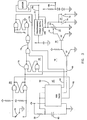
- Figures 1A-1E are block diagrams of preferred embodiment of vehicular mirror systems according to the present invention;
- Figure 2 is a more detailed block diagram of a preferred embodiment of a single-mirror control according to the invention;
- Figure 3 is a schematic diagram of a control circuit of a preferred embodiment of the invention;
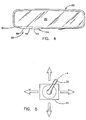
- Figure 4 illustrates a preferred embodiment of the invention when applied to an interior mirror;
- Figure 5 illustrates a remote mirror position control device employed in a preferable embodiment of the invention; and
- Figure 6 is a schematic diagram of a control circuit illustrating another preferred embodiment of the invention.
- Referring now specifically to the drawings and the illustrative embodiments depicted therein, a
mirror system 10 is illustrated as including adriver side mirror 12, typically mounted to the driver's door on the exterior of the vehicle, apassenger side mirror 13 mounted to the exterior of the passenger side door, aninterior mirror 14 mounted in the interior of the vehicle and acontrol 16 for providing signals overoutput lines mirrors mirrors lines -
Mirror system 10 additionally includes a first selection means 22, which is provided for the purpose of selecting a comfortable reflectivity level based upon particular driving conditions and the desires of the driver. As previously mentioned, the professional driver utilises mirrors as a primary driving aid and will typically select a reflectance level that provides exceptionally good visibility from the mirrors, even if occasional glare levels become somewhat uncomfortable.Mirror system 10 additionally includes asecond input device 24 that, when actuated, abruptly decreases the reflectivity of the mirrors. The second input device provides an override mode, or "panic button," for quickly responding to excessive glare conditions. Wheninput device 24 is actuated, mirrors 12, 13 and 14 are rapidly coloured to their minimum reflectivity level. When the glare condition ceases, a second actuation ofinput device 24 restores control over the reflectivity level ofmirrors first input device 22. If the driver does not return the mirrors to their higher reflectivity level after a predetermined period of time,control 16 will automatically do so. -
Mirror system 10 additionally includes athird input device 25 that, when actuated, rapidly increases the reflectivity of the mirrors to a high reflectance level. The third input device provides an override mode for rapidly providing high visibility in the mirrors when required by the driver. For example, when it is necessary to make lane-change condition, the driver may actuateinput device 25 in order to obtain the optimum image possible in themirrors input device 25 is deactuated, the reflectivity level of the mirrors is returned to that which existed prior to actuation of theinput device 25. If the user had previously actuated thesecond input device 24 in order to respond to a glare condition to lower the reflectivity of the mirrors and immediately actuatedinput device 25, in order to obtain high reflectivity to make a critical driving decision, the reflectivity level of the mirrors will return to the anti-glare low reflectivity level invoked by the actuation of thesecond input device 24. Under other circumstances, the reflectance level will return to the comfort level established by the first selection means 22 upon deactuation of thethird input device 25. Althoughinput device 25 may be a user actuatable device, it may additionally be made responsive to the condition of the vehicle. For example,input device 25 may be responsive to the vehicle being in the reverse-gear to provide a high reflectivity of the mirrors when the driver is backing the vehicle to a loading dock. - First
user input device 22 is illustrated as avariable potentiometer 26 that allows the user to select from a continuum of reflectivity levels based upon the position ofwiper 28. While it may be desirable to allow the driver to select any reflectivity level within the physical capability ofmirrors variable potentiometer 26 is capable of adjusting the reflectivity ofmirrors input device 24 allows the driver to temporarily relinquish some rear visibility in return for added glare protection. - In an embodiment illustrated in Figure 4, an
interior mirror 80 includes a variablereflective element 82 mounted within ahousing 84. In this embodiment,first input device 22 is illustrated in the form of a slew-control havingmomentary switches input device 24 is illustrated in the form of a singlemomentary switch 90.Switches - In the embodiment illustrated in Figure 5,
push button switch 30 is integrated with a "joystick" 90 used to adjust the position of the exterior mirrors 12, 14. In such embodiment, switch 30 could be actuated by pressing axially on the joystick as shown at A. Whilefirst input device 22 is illustrated as a continuously variable potentiometer, it may alternatively be a discrete step switch that selects between a finite number of discrete reflectance levels for the mirror or as a slew-control as illustrated in Figure 4.Input devices - In the embodiment illustrated in Figure 1A, the comfort reflectivity level of
mirrors first input device 22. Upon the experiencing of a glare condition, mirrors 12, 13 and 14 are also simultaneously coloured to a minimum reflectance level by the actuation of a singleuser input device 24. An alternative embodiment, illustrated in Figure 1B, includes separate comfort reflectance level controls 22A, 22B and 22C for establishing separate comfort levels formirrors override input device 24 causes mirrors 12, 13 and 14 to simultaneously colour to a low reflectivity state. In another alternative embodiment, illustrated in Figure 1C, asingle input device 22 establishes the comfort reflectance level ofmirrors - In the embodiment illustrated in Figure 1D,
second input device 24 is provided as a photosensor 95 that is configured in a manner to sense glare-producing light, i.e., that which is incident the mirror. This may be obtained by orientingphotosensor 95 to face rearwardly of the vehicle.Control 16 responds to photosensor 95 in a manner that the comfort level established byinput 22 will be overridden to the lower reflectivity level when the glare producing light sensed bysensor 95 is above a predetermined level. In this embodiment, the comfort level of reflectivity of the mirrors is manually established by the user, is selectively overridden by the detection of a glare condition and resumes the comfort level when the glare condition is no longer present. - In the embodiment illustrated in Figure 1E, the comfort level of the mirror system is established by
first input device 22′ which is a photosensor 29 that is configured to respond to the ambient light condition. This is achieved by orientingsensor 29 to respond other than to light directed incident the mirror surface and by providing a long time constant in the portion ofcontrol 16 that responds to thesensor 29. In terms of placement of the ambient sensor, it is preferred to place it in a location where the sensor is protected both from dirt and dust, and from head lamp glare, street lights, etc., that, otherwise, could create a false signal. The ambient light level in the interior cabin of the vehicle is an indication of the outside ambient level. Thus it is preferred to locate the ambient sensor within the interior cabin of the vehicle where it is protected from dirt, etc., and preferably facing away from glare sources such as approaching vehicles, street lights and the car interior lighting. The ambient photosensor can be located close to the mirror positioning/variable reflectance element manual circuitry controls, or can be separate. The sensor can be appropriately shielded so that its field of view avoids glare sources while it is measuring ambient light levels. - The ambient sensor can distinguish between high (day), medium (dusk/city driving), and low (dark country roads/highways) ambient levels and select any one of several comfort levels dependent on the level of ambient sensed. In terms of light intensity, a high ambient would be a light intensity in excess of 130 lux, or thereabouts. A medium ambient would be a light intensity in the region of 130 to 20 lux, or thereabouts. A low ambient would be a light intensity below about 20 lux. When used in a window system, as in some preferred embodiments of this invention, the ambient sensor is not directly facing the sun so as to be effected by solar glare. By so shielding from solar glare, and by providing a long time constant in the portion of the control circuit that responds to the ambient sensor, the variable transmission element (an electrochromic sunroof, for example) so controlled responds only to lasting and sustained changes in the ambient light level and does not exhibit rapid, and possibly objectionable, fluctuations in light transmittance due to changes in solar glare such as would occur when the sun passes between or through clouds on a sunny day.
- The use of an ambient sensor as the first input device has the advantage of the mirrors dimming to a particular comfort level when ambient lighting is low and returning to high reflectance when ambient is high. This is useful at dusk/dawn when the driver would like mirrors to dim, or dimmed mirrors to clear, without his/her personal intervention. In this embodiment, the comfort level of
mirror system 10′′′′ is greatest during high ambient conditions such as during daylight conditions and is lowered in response to lower ambient conditions. The comfort level may be either continuously varied as a direct proportion to the ambient light level or may be changed in a step-wise fashion. A user-operated sensitivity control can be provided to determine sensitivity of switching between the various comfort levels. Therefore, as the ambient condition decreases, for example as the driver begins to experience dusk, the reflectivity level of the mirror is decreased. This is important in a remotely actuated mirror system because the driver's eyes will become more sensitised to the low ambient condition and hence to any glare-producing light. When it is desired to have a high reflectivity state during such low-ambient condition, the user merely actuatesinput device 25 to cause the mirror system to rapidly assume a high reflectivity state. Of course,second input device 24 provides an override for high-glare conditions. However, the driver will typically desire the mirror to normally be at the comfort level established byinput 22′. Therefore, this embodiment of the invention incorporates use of an ambient sensor to determine the comfort level while retaining user selectable control over the return to high reflectance, and optionally retaining a manually selected or photoelectrically triggered second override to temporarily access the fullest dimmed state during periods of intense glare. - Thus, the first manual input means of the circuitry of this invention could be optionally replaced with an ambient detector such as a phototransistor whose suitably amplified and configured voltage output could serve as the voltage source to power the variable reflectance mirror to, at least, a comfort level from which further override means are optionally provided to achieve even greater glare protection; all the time, retaining manually (or reverse gear) selectable means to return to the high reflectance state. Alternatively, the ambient sensing means could control the mirror such that, by day, it is at full reflectance; at dawn/dusk and during city/highway driving, the mirror reflectivity is set to at least a lower comfort level; and at night during extremely low ambient such as is experienced in country road/highway driving, the variable reflectance element is controlled to colour to its fullest dimmed state.
- It should be emphasised that control of the mirror reflectance based on ambient sensing is distinct from control due to glare sensing. Thus, as shown in Figure 1E, one embodiment of this invention uses two photosensors, the first being an ambient light sensor and the second being a glare intensity detector.
Photosensor 22′ is an ambient sensing means that, dependent upon the intensity of ambient light detected, dims the mirror system within a reflectance range between the highest reflectance level (around 80%R for example) down to some comfort level (30%R for example). No matter how low the ambient, the control circuitry will not apply a voltage greater than that required to dim the mirror system to the desired comfort level.Photosensor 22′ is shielded from headlamp and direct sunlight glare and could be facing forward of the vehicle, or could be facing into the interior cabin (recall the interior cabin ambient is related to the exterior ambient) but not facing directly rearward or sidewards where it could be subject to headlamp glare, nor should it be subject to glare from interior lighting in the vehicle.Photosensor 95 is a rearward facing glare detector. Its circuitry can be such that it is activated only when the ambient sensor has established a comfort level close to 30%R or thereabouts. Upon detection of excessive glare,photodetector 95 selectively overrides the comfort level set by photosensor 22′ and dims the mirror to lower reflectance levels. For any ambient level detected by 22′ and for any excessive glare detected by 95, the bleached state is solely accessed through manual operation ofbleach control 25. - In an embodiment of
mirror system 10 illustrated in Figure 2, in which only one mirror (12) is illustrated for clarity, a resistance-programmable power supply 32 establishes a variable analog voltage on its output lines 18A, 18B extending to mirror 12. The value of the analog voltage on lines 18A, 18B is established by the resistance value across lines 34A and 34B that are input lines topower supply 32. The resistance between lines 34A and 34B is established by the position ofwiper 28 alongpotentiometer 26 if aswitch element 36 is closed, i.e., electrically interconnecting, or shorting,wiper 28 with line 34B. Ifswitch element 36 is open, then the resistance of the main winding ofpotentiometer 26 establishes the resistance between lines 34A and 34B irrespective of the position ofwiper 28. - The open/closed state of
switch element 36 is established by output lines 38A, 38B extending from aswitch element control 40.Switch element control 40 includes atimer circuit 42 which produces output on lines 38A, 38B and receives inputs onlines 44 extending from atimer control circuit 46.Timer control circuit 46 receives its input onlines 48 from a pushbutton debounce circuit 50 which, in turn, is connected with single pole momentary double-throw switch 30.Switch element control 40 and resistance-programmable power supply 32 receive regulated DC supply voltage from apower supply 52 that is powered from the vehicle'sbattery system 54. - Under normal driving conditions,
timer 42 produces signals on lines 38A, 38B causingswitch element 36 to be closed. This allows the user to select the reflectivity level ofmirror 12 by adjusting the position ofwiper 28 ofpotentiometer 26. The variable resistance provided by movement ofwiper 28 is translated bypower supply 32 into a variable analog signal on lines 18A, 18B. When the driver experiences a glare condition that the driver desires to be compensated for, the driver actuatespush button 30. Upon actuation ofpush button 30,timer 42 changes the state of the signal on lines 38A, 38B which causesswitch element 36 to open. This causes the resistance across lines 38A, 38B to be at a maximum value established by the resistance of the main winding ofpotentiometer 26, which corresponds to a maximum analog output on lines 18A, 18B. This colours mirror 12 to a minimum reflectivity level at a rapid rate. Ifpush button 30 is again actuated whiletimer 42 is timing,timer control 46 will respond by resettingtimer 42. This will cause the output oftimer 42 on lines 38A, 38B to againclose switch element 36 to return control of the reflectance level ofmirror 12 towiper 28 ofpotentiometer 26. Iftimer 42 times out withoutpush button 30 being pressed, it resets and produces outputs on lines 38A, 38B which closesswitch element 36 and returns control towiper 28. Therefore, afterwiper 28 is overridden by the actuation ofpush button 30, control is returned towiper 28 upon the first occurrence of the driverreactuating push button 30 ortimer 42 timing out. In the illustrative embodiment,timer 42 is set for 130 seconds but a shorter or longer period may be used. -
Input device 25, which includes aswitch 74/75 connected across lines 34A, 34B and in parallel withpotentiometer 26, will abruptly lower the resistance across lines 34A, 34B which will, in turn, cause a bleach voltage to be applied across lines 18A, 18B. This will abruptly increase the reflectance level ofmirror 12. Wheninput device 25 is deactuated, the output fromprogrammable power supply 32 to mirror 12 will resume the value that it had prior to actuation ofinput device 25. - A detailed embodiment of
control 16 is illustrated in Figure 3, in which aconventional timer circuit 56, whose time duration is established by aresistor 58 andcapacitor 60, is set by the actuation of itsset line 62 and reset by actuation of itsreset line 64. When set,timer circuit 56 produces an output online 66 that turns a transistor Q1 on which turns off, or opens, a transistor Q2. Transistors Q1 and Q2 defineswitch element 36. Resistance-programmable power supply 32 produces an output on line 18A that is proportional to the resistance on its input line 34A, which is established by the resistance ofpotentiometer 26, irrespective of the position ofwiper 28, when transistor Q2 is turned off. Transistor Q2 is turned on whentimer circuit 56 is reset with its output online 66 at a low level, which causes transistor Q1 to be open and Q2 to be conducting.Timer control circuit 46 includes a latch-circuit 70 which produces an output online 72 whenswitch 30 is actuated withoutput 66 in a set state. This produces, in turn, a reset pulse online 64 to resettimer circuit 56 if it is timing. Iftimer circuit 56 is not timing, the actuation ofswitch 30 does not produce a reset pulse online 64. - In the embodiment illustrated in Figure 3, a
switch 74, when closed,shorts potentiometer 26. This causes the output on lines 18A and 18B to go to the minimum analog output voltage which is a maximum reflectivity condition. Thus, switch 74 may serve as a manual override device in order to place themirror system 10 in a maximum reflectivity state. Anotherswitch 75, which is connected in parallel withswitch 74, may be actuated by the reverse-gear of the vehicle in order to placemirror system 10 in a maximum reflectivity state when the vehicle is being backed into a loading dock. When both switches 74 and 75 are then open, the reflectivity of the mirror returns to the comfort level previously set by the driver, or to the low-reflectivity level established by the switch element control. - Because the
override input device 24 is intended to rapidly force the associated mirrors 12, 13 and 14 to a minimum reflectivity level, it may be desirable to provide a dynamic circuit betweenpower supply 32 and the mirror to increase the rate of coloration of the mirror. Such rapid coloration feature is described in EP-A-0426503. A temporary overshoot is provided in the voltage supplied on lines 18A, 18B in order to rapidly colour the mirror. The overshoot is of a short enough duration to not damage the mirror. -
Mirrors override input 25 is selected. Typically, such an all-solid state electrochromic mirror is capable of substantially bleaching within one to three seconds. Additionally, reflectivity values of as great as 70-80% may be achieved. This is most desirable in the present application because it allows the professional driver exceptionally high visibility for making lane-change decisions and backing into loading docks and the like. However, the embodiments of the invention preferably provide a comfort level that will typically be in the range of 20-60% which is the level preferred by many drivers during periods of moderate glare. When the high reflectivity condition is required, it is rapidly achieved by actuation of the override means 25 to rapidly bleach the all solid-state electrochromic mirror. - In an embodiment illustrated in Figure 6,
mirror system 110 includes a first resistanceprogrammable power supply 113 and a second resistanceprogrammable power supply 114.Programmable power supply terminal 116. Theoutput 118 ofpower supply 113 is connected through a pair of forwardly poled diodes 120A, 120B through aline 122 which provides a voltage level representative of a high reflectivity condition. The voltage level online 122 is established by apotentiometer 124 which provides an input topower supply 113 online 126. Resistanceprogrammable power supply 114 provides an output on aline 128 which is determined by a resistance value established at aninput 130 thereof.Input 130 is, in turn, established by arotary switch 132 which is selectively connected with aground terminal 134, a terminal 136, 138, 140, 142 or 143.Terminal 136 is connected through apotentiometer 144 to ground.Terminal 138 is connected through apotentiometer 146 to ground.Terminal 140 is connected through apotentiometer 148 to ground, andterminal 142 is connected throughpotentiometer 150 to ground. Terminal 143 is at open-circuit.Potentiometers 144 through 150 are adjusted in order to provide selectable resistance values oninput 130 which correspond to reflectance levels onmirror 112 that are at discrete values such as 10%, 20%, 30% and the like. -
Output 122 frompower supply 113 andoutput 128 frompower supply 114 are provided to opposite terminals of a double-pole double-throw (DPDT)switch 152.Switch 152 is an override switch that allows the user to selectively apply the voltage online 122 to themirror 112 in order to select a high reflectivity state for the mirror. The outputs fromswitch 152 are, in turn, connected to anotherDPDT switch 154 which is responsive to the vehicle being placed in a reverse gear, in order to apply the voltage online 122 acrossmirror 112. The output fromswitch 154 is, in turn, connected with aDPDT switch 156, which is interconnected with the vehicle's headlights in a manner that the voltage online 122 will be connected withmirror 112 when the vehicle's headlights are off in order to place the mirror in a high reflectance state during high ambient conditions, such as during daylight hours. In contrast, the comfort level established by the voltage online 128 will be applied tomirror 112 through the arrangement ofswitches mirror 112 is established by the manual setting ofswitch 132. - In the event that power to the circuit is lost while the mirror is in a dimmed state,
resistor 196 serves as a low resistance path to drain whatever charge is stored in the variable reflective element so that it rapidly rises in reflectivity to its highest reflectance level. For electrochromic mirrors powered by applied DC potentials in the 0.5V to 2V range,resistor 196 is typically 43 ohms in resistance, or thereabouts, and is rated at 1 watt.Resistor 196 thus serves as a fail-to-day means should power be lost. Alternatively, a relay contact could be held open when the circuit is powered but which, if power is lost, closes so as to short the electrodes onmirror 112 and thereby rapidly bleach it to its highest reflectance level. -
Resistor 198 is a low resistance (1 ohm or thereabouts) resistor placed in series with thevariable reflectance mirror 112.Resistor 198 is a current limiting resistor intended to limit the initial large current transient typical upon first coloration or bleach of electrochromic devices. Use ofresistor 198 has the beneficial effect of avoiding a large current surge through the circuitry and intomirror 112 whenever the mirror is coloured from the bleached state down to a dimmed reflectance level, and of assisting uniformity of coloration and bleaching across large-area devices. Electrochromic devices, upon first application of voltage, typically colour fastest and deepest in the perimetal regions closest to the busbars. Coloration in the central region lags that of the perimetal regions so that coloration is observed, and is most noticeable if rapid, as an iris-type wave from the perimetal regions to the centre. Conversely, bleaching is fastest in the perimetal regions and is somewhat slower in the central region so that bleaching is observed, and is most noticeable if rapid, as an inverse iris-type wave from the perimetal regions into the central region. By limiting the initial coloration and initial bleach current, and thereby limiting the applied potential,resistor 198 slows both coloration and bleaching such that the iris effects described above are averaged over a longer time duration and thus are less noticeable to the viewer. Use ofresistor 198 in the circuitry of Figure 6 is particularly appropriate when driving large area, all solid-state electrochromic devices (such as 400mm x 150mm (16˝ x 6˝) truck mirrors) of the type disclosed in US-A-4,712,879. The bleach speed of all-solid state electrochromic devices is sufficiently fast that use of a 1 ohm, or thereabouts, resistor in series therewith beneficially slows the very rapid bleach speed (and thereby facilitating use of less conductive and more economic transparent conducting layers in the device design) but with the bleach speed still remaining close to the rapid bleach response desired for manually operated devices. - As a specific example of the combination of the specialised circuitry of Figure 6 with an electrochromic mirror element, the resistance
programmable power supplies potentiometer 131 set for 109 ohms,potentiometers output 128 of resistanceprogrammable power supply 114 to be approximately 1.25 volts, 1.3 volts, 1.4 volts, 1.5 volts, 1.6 volts and 1.8 volts forterminal positions rotary switch 132. Withmirror element 112 being an all solid-state electrochromic mirror designed to achieve a minimum reflectance close to 10% at 1.8 volts applied, and of the type disclosed in US-A-4,712,879, the various discrete voltages above online 128 would correspond to mirror reflectances of approximately 44%, 40%, 30%, 20%, 12% and 10%, respectively. Also, withresistor 229 being 240 ohms andpotentiometer 124 set to 200 ohms andresistor 339 being 43 ohms, theoutput 122 of resistanceprogrammable power supply 113 is set to provide -0.8V as a voltage level representative of the high reflectivity condition of the all solid-state electrochromic mirror. When forward biased,silicon diodes 120a, 120b each individually reduce the voltage output online 118 by approximately 0.7V. - While embodiments of the invention have been described with reference to use by professional drivers and with large vehicles such as large trucks, its advantages are not limited in this manner and it may be useful in other applications. Memory means may be provided within
control 16 such that the comfort setting of the mirror system for various drivers may be stored and called up when that driver is operating the vehicle. The input devices could be positioned at various locations, for example on or adjacent to the steering wheel or the steering column. - Embodiments of the present invention are not only functional and capable of providing optimum individual control to the driver, but are also natural in their use. Accordingly, its incorporation with other control devices, such as mirror-positioning devices that are already familiar to the driver, tends to cause the features of the invention to become second-nature to the driver with minimum or no instructions. This is especially important when the invention is applied to rental cars or in other applications where driver familiarity with the vehicle cannot be taken for granted. Also, the natural feel to the control will enhance the instinctive reactions of the driver and serve as an extension of the driver's control over the vehicle.
- In a preferable embodiment of the invention, a rearview mirror system for a vehicle comprises a reflective element having a controllable variable reflectivity; a control that is adapted to establishing the level of reflectivity of said reflective element; a first input device for said control that is adapted to causing said control to establish a first level of reflectivity of said reflective element; a second input device for said control that is selectively actuatable in order to cause said control to establish a second level of reflectivity of said reflective element that is less than said first level, wherein actuation of said second user input device selectively overrides said first user input device when actuated; a third input device for said control that is selectively actuatable in order to cause said control to establish a third level of reflectivity of said reflective element that is greater than said first level, wherein actuation of said third input device selectively overrides said first and second input devices when actuated; and wherein said control returns the level of reflectivity of said reflective element upon deactuation of said third input device to the one of said first and second levels that existed upon actuation of said third input device.
Claims (42)
- A rearview mirror system for a vehicle comprising a reflective element (12,13,14) having a controllable variable reflectivity, a control (16) which is adapted to establish the level of reflectivity of the reflective element, a first input device (22,22′) for the control which is adapted to cause the control to establish a first level of reflectivity of the reflective element, a second input device (25) for the control which is selectively actuatable in order to cause the control to establish a second level of reflectivity of the reflective element that is greater than the first level, actuation of the second input device selectively overriding the first input device when actuated, the control being adapted to return the level of reflectivity of the reflective element to the first level upon deactuation of the second input device.
- A system as claimed in claim 1 in which the element is arranged to change reflectivity from the first to the second level at a faster rate than from the second to the first level.
- A rearview mirror system for a vehicle comprising a reflective element (12,13,14) having a controllable variable reflectivity, a control (16) that is adapted to establish the level of reflectivity of the reflective element, a first input device (22,22′) for the control which is adapted to cause the control to establish a first level of reflectivity of the reflective element, a second input device (25) for the control which is selectively actuatable in order to cause the control to establish a second level of reflectivity of the reflective element that is greater than the first level, actuation of the second input device selectively overriding the first input device when actuated, the reflective element being arranged to change from the first to the second level at a faster rate than from the second to the first level.
- A system as claimed in claim 1 or claim 2 or claim 3 including a third input device (24) for the control which is selectively actuatable in order to cause the control to establish a third level of reflectivity of the reflective element that is less than the first level, actuation of the third user input device (24) selectively overriding the first user input device when actuated, actuation of the second input device (25) selectively overriding the first and the third input devices when actuated, the control being adapted to return the level of reflectivity of the reflective element upon deactuation of the second input device to the one of the first and third levels that existed upon actuation of the second input device.
- A system as claimed in claim 4 in which the reflective element is arranged to change reflectivity from one of the first and third levels to the second level at a faster rate than from the second level to one of the first and third levels.
- A system as claimed in claim 4 or claim 5 in which the third input device (24) is user manipulable in order to selectively establish the third reflectance level.
- A system as claimed in claim 4 or claim 5 in which the third input device comprises a photosensor (95) that is responsive to glare-producing light exceeding a predetermined level.
- A system as claimed in any one of claims 4 to 7 including resume means (42) adapted to cause the third input device the cease being actuated.
- A system as claimed in claim 8 in which the resume means includes timer means (42) adapted to cause the third input device to cease being actuated a predetermined time duration after being actuated.
- A system as claimed in claim 9 in which the resume means includes user override means (30) that is user actuatable for causing the third input device to cease being actuated during the predetermined time duration.
- A system as claimed in any one of the preceding claims in which the first input device (22,22′) is adapted to cause the control to establish the first level from a continuously variable range of reflectivity values.
- A system as claimed in any one of the preceding claims in which the second level is at least 60% reflectance.
- A system as claimed in any one of the preceding claims in which the reflective element has a range of reflectivity values, and the first input device (22,22′) is adapted to cause the control to establish the first level from a second range of reflectivity values which is more narrow than the range of reflectivity of the reflective element.
- A system as claimed in claim 13 in which the second range of reflectivity values is between 20% and 80%.
- A system as claimed in any one of the preceding claims in which the first input device (22) is user manipulable for manually establishing a desired comfort level of reflectivity.
- A system as claimed in any one of claims 1 to 14 in which the first input device (22′) comprises an ambient light sensor (29).
- A system as claimed in claim 16 in which the reflective element comprises an exterior mirror (12,13) and the ambient light sensor (29) is positioned in an interior portion of the vehicle.
- A system as claimed in claim 16 or claim 17 in which the control (16) lowers the first level of reflectivity in response to lower level of ambient light sensed by the ambient light sensor (29).
- A system as claimed in any one of the preceding claims including another reflective element (12,13,14) having a controllable variable reflectivity, the control being adapted to control the reflectivity of both elements.
- A system as claimed in claim 19 in which the first input device (22,22′) is adapted to cause the control to establish the first level of reflectivity for both of the elements.
- A system as claimed in any one of the preceding claims in which the second input device (25) is user manipulable in order to selectively establish the second reflectance level.
- A system as claimed in any one of the preceding claims in which the second input device is actuated in response to the vehicle being placed in reverse gear.
- A system as claimed in any one of the preceding claims in which the vehicle includes headlights and switch means (156) for selectively actuating the headlights, and the first input device is actuated in response to the switch means actuating said headlights.
- A system as claimed in claim 23 in which the second input device is actuated in response to the vehicle being placed in reverse gear irrespective of whether the switch means is actuating said headlights.
- A system as claimed in any one of the preceding claims including means (196) for causing a said reflectance element to achieve a maximum reflectivity value when electrical power to the system is interrupted.
- A system as claimed in claim 17 in which the ambient light sensor is used exclusively in the system.
- A system as claimed in claim 17 in which the ambient light sensor is used concurrently with one of an automatic mirror control and a twilight sentinel.
- A light transmitting system for a vehicle comprising a light transmitting element (12,13,14) having a controllable variable level of light attenuation, a control (16) which is adapted to establish the level of attenuation of the transmitting element, a first input device (22,22′) for the control which is adapted to cause the control to establish a first level of attenuation of the transmitting element, a second input device (25) for the control which is selectively actuatable in order to cause the control to establish a second level of attenuation of the transmitting element which has a predetermined relationship to the first level, actuation of the second input device selectively overriding the first input device when actuated, the control being adapted to return the level of attenuation of the transmitting element to the first level upon deactuation of the second input device.
- A system as claimed in claim 28 in which the transmitting element has a range of attenuation values and the first input device (22,22′) is adapted to cause the control to establish the first level from a second range of attentuation values which is more narrow than the range of attenuation of the transmitting element.
- A system as claimed in claim 28 or claim 29 in which the transmitting element is a window.
- A system as claimed in claim 30 in which the control is adapted to establish a level of attenuation of the transmitting element that increases for increasing levels of ambient light.
- A system as claimed in claim 28 or claim 29 in which the light transmitting element is a rearview mirror (12,13,14,80).
- A system as claimed in claim 32 in which the control is adapted to establish a level of attenuation of the transmitting element that decreases for increasing levels of ambient light.
- A system as claimed in claim 32 or claim 33 in which the mirror is located at an exterior portion of the vehicle.
- A system as claimed in any one of claims 28 to 34 in which the first input device is an ambient light sensor (29).
- A system as claimed in claim 35 in which the ambient light sensor is located at an interior portion of said vehicle.
- A system as claimed in any one of the preceding claims which includes current limiting means (198) adapted to control the rate of change between levels in a said element.
- A system as claimed in claim 37 in which the current limiting means comprises a resistor (198) in series with the said element.
- A system as claimed in any one of the preceding claims in which a said element comprises an all solid-state electrochromic element.
- A system as claimed in any one of the preceding claims in which a said element includes a multiple-layer stack of inorganic metal oxide thin film layers.
- A system as claimed in claim 40 in which the multiple-layer stack includes an anodically colouring electrochromic film and a cathodically colouring electrochromic film.
- A system as claimed in claim 40 or claim 41 in which the multiple-layer stack includes an ion transporting and electron insulating inorganic metal oxide film.
Applications Claiming Priority (4)
| Application Number | Priority Date | Filing Date | Title |
|---|---|---|---|
| US565652 | 1990-08-10 | ||
| US07/565,652 US5122647A (en) | 1990-08-10 | 1990-08-10 | Vehicular mirror system with remotely actuated continuously variable reflectance mirrors |
| US07/615,228 US5148014A (en) | 1990-08-10 | 1990-11-19 | Mirror system with remotely actuated continuously variable reflectant mirrors |
| US615228 | 1990-11-19 |
Publications (1)
| Publication Number | Publication Date |
|---|---|
| EP0470866A1 true EP0470866A1 (en) | 1992-02-12 |
Family
ID=27073927
Family Applications (1)
| Application Number | Title | Priority Date | Filing Date |
|---|---|---|---|
| EP91307387A Withdrawn EP0470866A1 (en) | 1990-08-10 | 1991-08-12 | Light transmitting and mirror systems for vehicles |
Country Status (3)
| Country | Link |
|---|---|
| US (1) | US5148014A (en) |
| EP (1) | EP0470866A1 (en) |
| JP (1) | JPH0680052A (en) |
Cited By (10)
| Publication number | Priority date | Publication date | Assignee | Title |
|---|---|---|---|---|
| EP0614784A1 (en) * | 1993-03-09 | 1994-09-14 | Murakami Kaimeido Co., Ltd | Anti-glare rearview mirror system |
| DE4410752A1 (en) * | 1993-03-29 | 1994-11-17 | Tokai Rika Co Ltd | Control device for an anti-dazzle mirror |
| EP0638835A1 (en) * | 1993-01-19 | 1995-02-15 | Moskovskoe Nauchno-Proizvodstvennoe Obiedinenie "Niopik" | Electronic unit for the automatic control of electrochromic rear-view vehicle mirrors |
| GB2338570A (en) * | 1998-10-28 | 1999-12-22 | Ho Keung Tse | Performing vehicle control functions in dependence on whether the vehicle is stationary |
| EP1001307A2 (en) * | 1998-11-12 | 2000-05-17 | Murakami Corporation | Electrochromic device drive unit for use with a rear-view mirror |
| WO2001082656A1 (en) * | 2000-10-10 | 2001-11-01 | Elumina Lighting Technologies, Inc. | Electroluminescent lighting device |
| US6337541B1 (en) | 1999-10-08 | 2002-01-08 | Robert G. Dickie | Electroluminescent lighting device |
| AU769017B2 (en) * | 1998-10-28 | 2004-01-15 | Ho Keung Tse | Vehicle window transmissivity control |
| EP1477784A1 (en) * | 2003-05-13 | 2004-11-17 | Exon Science Inc. | Automatic actuation of device according to UV intensity |
| US6872901B2 (en) | 2002-11-21 | 2005-03-29 | Exon Science Inc. | Automatic actuation of device according to UV intensity |
Families Citing this family (79)
| Publication number | Priority date | Publication date | Assignee | Title |
|---|---|---|---|---|
| US5451822A (en) * | 1991-03-15 | 1995-09-19 | Gentex Corporation | Electronic control system |
| US5202787A (en) * | 1992-01-10 | 1993-04-13 | Gentex Corporation | Electro-optic device |
| US5285060A (en) * | 1992-12-15 | 1994-02-08 | Donnelly Corporation | Display for automatic rearview mirror |
| US5670935A (en) | 1993-02-26 | 1997-09-23 | Donnelly Corporation | Rearview vision system for vehicle including panoramic view |
| EP1004649A3 (en) * | 1993-02-26 | 2000-07-26 | Donnelly Corporation | Electrochromic polymeric solid films, manufacturing electrochromic devices using such solid films, and processes for making such solid films and devices |
| US5910854A (en) * | 1993-02-26 | 1999-06-08 | Donnelly Corporation | Electrochromic polymeric solid films, manufacturing electrochromic devices using such solid films, and processes for making such solid films and devices |
| US5877897A (en) | 1993-02-26 | 1999-03-02 | Donnelly Corporation | Automatic rearview mirror, vehicle lighting control and vehicle interior monitoring system using a photosensor array |
| US6822563B2 (en) | 1997-09-22 | 2004-11-23 | Donnelly Corporation | Vehicle imaging system with accessory control |
| US5550677A (en) * | 1993-02-26 | 1996-08-27 | Donnelly Corporation | Automatic rearview mirror system using a photosensor array |
| JP2971735B2 (en) * | 1994-04-13 | 1999-11-08 | 株式会社村上開明堂 | Drive device for EC anti-glare mirror |
| US5668663A (en) | 1994-05-05 | 1997-09-16 | Donnelly Corporation | Electrochromic mirrors and devices |
| US5812321A (en) * | 1994-07-19 | 1998-09-22 | Donnelly Corporation | Automatic sensitivity adjustment for electro-optic mirror and headlight activation control |
| EP0693397B1 (en) * | 1994-07-19 | 2002-09-11 | Donnelly Corporation | Automatic rearview mirror system with automatic headlight activation |
| US6891563B2 (en) | 1996-05-22 | 2005-05-10 | Donnelly Corporation | Vehicular vision system |
| US7655894B2 (en) | 1996-03-25 | 2010-02-02 | Donnelly Corporation | Vehicular image sensing system |
| EP0923754A1 (en) | 1996-08-20 | 1999-06-23 | Donnelly Corporation | Window assembly with controllable optical transmission |
| US6056410A (en) | 1997-04-02 | 2000-05-02 | Donnelly Corporation | Digital electrochromic mirror system |
| US6089721A (en) | 1997-04-02 | 2000-07-18 | Donnelly Corporation | Digital electrochromic mirror system |
| US5969870A (en) * | 1997-09-18 | 1999-10-19 | Anvik Corporation | Remotely adjustable, anti-glare vehicle mirror system |
| US6317248B1 (en) | 1998-07-02 | 2001-11-13 | Donnelly Corporation | Busbars for electrically powered cells |
| US6678083B1 (en) | 1999-02-26 | 2004-01-13 | Schefenacker Vision Systems Uk Ltd. | Electrochromic mirror assembly |
| US7370983B2 (en) | 2000-03-02 | 2008-05-13 | Donnelly Corporation | Interior mirror assembly with display |
| US6759945B2 (en) * | 2001-03-29 | 2004-07-06 | Vtec Technologies, Inc. | Variable transmittance birefringent device |
| US6882287B2 (en) | 2001-07-31 | 2005-04-19 | Donnelly Corporation | Automotive lane change aid |
| US7697027B2 (en) | 2001-07-31 | 2010-04-13 | Donnelly Corporation | Vehicular video system |
| ES2391556T3 (en) | 2002-05-03 | 2012-11-27 | Donnelly Corporation | Object detection system for vehicles |
| DE10338398A1 (en) * | 2003-08-21 | 2005-05-12 | Schefenacker Vision Systems | Rearview mirrors for vehicles, preferably motor vehicles |
| US7446924B2 (en) | 2003-10-02 | 2008-11-04 | Donnelly Corporation | Mirror reflective element assembly including electronic component |
| US7308341B2 (en) | 2003-10-14 | 2007-12-11 | Donnelly Corporation | Vehicle communication system |
| US7526103B2 (en) | 2004-04-15 | 2009-04-28 | Donnelly Corporation | Imaging system for vehicle |
| US7881496B2 (en) | 2004-09-30 | 2011-02-01 | Donnelly Corporation | Vision system for vehicle |
| US7270433B2 (en) * | 2004-10-20 | 2007-09-18 | Illinois Tool Works Inc | Mirror switch assembly |
| US7720580B2 (en) | 2004-12-23 | 2010-05-18 | Donnelly Corporation | Object detection system for vehicle |
| WO2008024639A2 (en) | 2006-08-11 | 2008-02-28 | Donnelly Corporation | Automatic headlamp control system |
| US8013780B2 (en) | 2007-01-25 | 2011-09-06 | Magna Electronics Inc. | Radar sensing system for vehicle |
| US8345345B2 (en) | 2007-06-27 | 2013-01-01 | Gentex Corporation | Electrochromic device having an improved fill port plug |
| WO2009002556A1 (en) * | 2007-06-27 | 2008-12-31 | Gentex Corporation | Electrochromic device having an improved fill port plug |
| US7914187B2 (en) | 2007-07-12 | 2011-03-29 | Magna Electronics Inc. | Automatic lighting system with adaptive alignment function |
| US8017898B2 (en) | 2007-08-17 | 2011-09-13 | Magna Electronics Inc. | Vehicular imaging system in an automatic headlamp control system |
| WO2009036176A1 (en) | 2007-09-11 | 2009-03-19 | Magna Electronics | Imaging system for vehicle |
| US8446470B2 (en) | 2007-10-04 | 2013-05-21 | Magna Electronics, Inc. | Combined RGB and IR imaging sensor |
| US20100020170A1 (en) | 2008-07-24 | 2010-01-28 | Higgins-Luthman Michael J | Vehicle Imaging System |
| WO2010099416A1 (en) | 2009-02-27 | 2010-09-02 | Magna Electronics | Alert system for vehicle |
| WO2011014497A1 (en) | 2009-07-27 | 2011-02-03 | Magna Electronics Inc. | Vehicular camera with on-board microcontroller |
| WO2011014482A1 (en) | 2009-07-27 | 2011-02-03 | Magna Electronics Inc. | Parking assist system |
| US8200390B2 (en) * | 2009-07-30 | 2012-06-12 | Control Solutions LLC | Securable cover for vehicle lights |
| US8248680B2 (en) * | 2009-07-31 | 2012-08-21 | Control Solutions LLC | Electrically activatable light blocking cover for vehicle mirrors |
| ES2538827T3 (en) | 2009-09-01 | 2015-06-24 | Magna Mirrors Of America, Inc. | Imaging and display system for a vehicle |
| US8890955B2 (en) | 2010-02-10 | 2014-11-18 | Magna Mirrors Of America, Inc. | Adaptable wireless vehicle vision system based on wireless communication error |
| US9117123B2 (en) | 2010-07-05 | 2015-08-25 | Magna Electronics Inc. | Vehicular rear view camera display system with lifecheck function |
| WO2012068331A1 (en) | 2010-11-19 | 2012-05-24 | Magna Electronics Inc. | Lane keeping system and lane centering system |
| US9900522B2 (en) | 2010-12-01 | 2018-02-20 | Magna Electronics Inc. | System and method of establishing a multi-camera image using pixel remapping |
| US9264672B2 (en) | 2010-12-22 | 2016-02-16 | Magna Mirrors Of America, Inc. | Vision display system for vehicle |
| WO2012103193A1 (en) | 2011-01-26 | 2012-08-02 | Magna Electronics Inc. | Rear vision system with trailer angle detection |
| US9357208B2 (en) | 2011-04-25 | 2016-05-31 | Magna Electronics Inc. | Method and system for dynamically calibrating vehicular cameras |
| US10793067B2 (en) | 2011-07-26 | 2020-10-06 | Magna Electronics Inc. | Imaging system for vehicle |
| WO2013019707A1 (en) | 2011-08-01 | 2013-02-07 | Magna Electronics Inc. | Vehicle camera alignment system |
| US9146898B2 (en) | 2011-10-27 | 2015-09-29 | Magna Electronics Inc. | Driver assist system with algorithm switching |
| US9491451B2 (en) | 2011-11-15 | 2016-11-08 | Magna Electronics Inc. | Calibration system and method for vehicular surround vision system |
| US8694224B2 (en) | 2012-03-01 | 2014-04-08 | Magna Electronics Inc. | Vehicle yaw rate correction |
| US9340227B2 (en) | 2012-08-14 | 2016-05-17 | Magna Electronics Inc. | Vehicle lane keep assist system |
| DE102013217430A1 (en) | 2012-09-04 | 2014-03-06 | Magna Electronics, Inc. | Driver assistance system for a motor vehicle |
| US9558409B2 (en) | 2012-09-26 | 2017-01-31 | Magna Electronics Inc. | Vehicle vision system with trailer angle detection |
| US9446713B2 (en) | 2012-09-26 | 2016-09-20 | Magna Electronics Inc. | Trailer angle detection system |
| US9723272B2 (en) | 2012-10-05 | 2017-08-01 | Magna Electronics Inc. | Multi-camera image stitching calibration system |
| US9090234B2 (en) | 2012-11-19 | 2015-07-28 | Magna Electronics Inc. | Braking control system for vehicle |
| US9092986B2 (en) | 2013-02-04 | 2015-07-28 | Magna Electronics Inc. | Vehicular vision system |
| US9057925B2 (en) | 2013-03-15 | 2015-06-16 | Gentex Corporation | Fill port plugs for electrochromic devices |
| US9327693B2 (en) | 2013-04-10 | 2016-05-03 | Magna Electronics Inc. | Rear collision avoidance system for vehicle |
| US9205776B2 (en) | 2013-05-21 | 2015-12-08 | Magna Electronics Inc. | Vehicle vision system using kinematic model of vehicle motion |
| US9563951B2 (en) | 2013-05-21 | 2017-02-07 | Magna Electronics Inc. | Vehicle vision system with targetless camera calibration |
| US9260095B2 (en) | 2013-06-19 | 2016-02-16 | Magna Electronics Inc. | Vehicle vision system with collision mitigation |
| US20140375476A1 (en) | 2013-06-24 | 2014-12-25 | Magna Electronics Inc. | Vehicle alert system |
| US9454054B2 (en) | 2013-11-18 | 2016-09-27 | Magna Mirrors Of America, Inc. | Electro-optic mirror element and process of making same |
| US9916660B2 (en) | 2015-01-16 | 2018-03-13 | Magna Electronics Inc. | Vehicle vision system with calibration algorithm |
| US10078789B2 (en) | 2015-07-17 | 2018-09-18 | Magna Electronics Inc. | Vehicle parking assist system with vision-based parking space detection |
| US10875403B2 (en) | 2015-10-27 | 2020-12-29 | Magna Electronics Inc. | Vehicle vision system with enhanced night vision |
| US10132971B2 (en) | 2016-03-04 | 2018-11-20 | Magna Electronics Inc. | Vehicle camera with multiple spectral filters |
| US9994091B2 (en) * | 2016-08-12 | 2018-06-12 | GM Global Technology Operations LLC | Window system for a passenger compartment of a vehicle |
Citations (9)
| Publication number | Priority date | Publication date | Assignee | Title |
|---|---|---|---|---|
| US3862798A (en) * | 1973-11-19 | 1975-01-28 | Charles L Hopkins | Automatic rear view mirror adjuster |
| GB2156545A (en) * | 1984-03-30 | 1985-10-09 | Gentex Corp | Electronic control system for automatic rearview mirrors for automotive vehicles |
| EP0201938A2 (en) * | 1985-05-17 | 1986-11-20 | C-D Marketing, Ltd. | Liquid crystal controlled mirror systems |
| US4634835A (en) * | 1984-08-01 | 1987-01-06 | Kabushiki Kaisha Tokai Denki Seisakusha | Anti-dazzle device for a rearview mirror of a motor vehicle |
| US4701022A (en) * | 1984-11-28 | 1987-10-20 | C-D Marketing, Ltd. | Day/night mirror |
| EP0280278A2 (en) * | 1987-02-27 | 1988-08-31 | Ichikoh Industries Limited | Light-reflectivity controller for use with automotive rearview mirror using electrochromic element |
| EP0304198A2 (en) * | 1987-08-21 | 1989-02-22 | General Motors Corporation | Electrooptical device |
| US4832467A (en) * | 1986-08-11 | 1989-05-23 | Nissan Motor Co., Ltd. | Electrochromic variable color tone nonglaring mirror |
| GB2233468A (en) * | 1989-06-24 | 1991-01-09 | Martin Spence Wilson | Electronic reduction of glare |
Family Cites Families (39)
| Publication number | Priority date | Publication date | Assignee | Title |
|---|---|---|---|---|
| US3451741A (en) * | 1966-06-15 | 1969-06-24 | Du Pont | Electrochromic device |
| US3521941A (en) * | 1967-02-07 | 1970-07-28 | American Cyanamid Co | Electro-optical device having variable optical density |
| US3578843A (en) * | 1968-09-25 | 1971-05-18 | American Cyanamid Co | Control of light reflected from a mirror |
| US3774988A (en) * | 1969-09-02 | 1973-11-27 | Polaroid Corp | Variable light-filtering device |
| US3708220A (en) * | 1970-05-25 | 1973-01-02 | American Cyanamid Co | High conductivity electrolyte gel materials |
| US3807832A (en) * | 1972-11-09 | 1974-04-30 | American Cyanamid Co | Electrochromic (ec) mirror which rapidly changes reflectivity |
| US4088392A (en) * | 1975-04-13 | 1978-05-09 | American Cyanamid Company | Electrochromic variable optical transmission device with a liquid electrolyte |
| GB1586104A (en) * | 1976-07-12 | 1981-03-18 | Matsushita Electric Ind Co Ltd | Electrochromic display apparatus and method |
| DE2737564C2 (en) * | 1976-09-02 | 1985-05-02 | Matsushita Electric Industrial Co., Ltd., Kadoma, Osaka | Color display device with redox reaction products formed on an indicator electrode |
| US4201451A (en) * | 1976-09-03 | 1980-05-06 | Donald F. Hassinger | Wide angled rear view mirror apparatus |
| IT1117275B (en) * | 1977-02-25 | 1986-02-17 | Remo Bedini | AUTOMATIC METHOD AND DEVICE FOR THE ATTENTION OF THE DRIVING PHENOMENA IN REFLECTED LIGHT |
| JPS5550294A (en) * | 1978-10-09 | 1980-04-11 | Nippon Chemical Ind | Device for driving display unit having storage property |
| JPS5588028A (en) * | 1978-12-27 | 1980-07-03 | Nippon Kogaku Kk <Nikon> | Solid electrochromic element |
| DE2934451A1 (en) * | 1979-08-25 | 1981-03-12 | Vdo Adolf Schindling Ag, 6000 Frankfurt | DEGREBABLE REAR MIRROR, ESPECIALLY FOR MOTOR VEHICLES. |
| JPS57173801A (en) * | 1981-04-21 | 1982-10-26 | Ichikoh Ind Ltd | Reflection factor variable mirror device |
| JPS57208530A (en) * | 1981-06-19 | 1982-12-21 | Ichikoh Ind Ltd | Antidazzling mirror device |
| JPS57208531A (en) * | 1981-06-19 | 1982-12-21 | Ichikoh Ind Ltd | Automatic dazzle-resistant mirror device |
| DE3142907A1 (en) * | 1981-10-29 | 1983-05-11 | Fa. Carl Zeiss, 7920 Heidenheim | OPTICAL CONTROL CIRCUIT FOR ELECTROCHROME LAYERS |
| DE3142909A1 (en) * | 1981-10-29 | 1983-05-11 | Fa. Carl Zeiss, 7920 Heidenheim | CONTINUOUS CHARGE CONTROL FOR ELECTROCHROME LAYERS |
| DE3142906A1 (en) * | 1981-10-29 | 1983-05-11 | Fa. Carl Zeiss, 7920 Heidenheim | STAGE CHARGE CONTROL FOR ELECTROCHROME LAYERS |
| US4623222A (en) * | 1983-11-14 | 1986-11-18 | Nippondenso Co., Ltd. | Liquid crystal type dazzle-free transmissive-reflective mirror |
| DE3474650D1 (en) * | 1983-11-14 | 1988-11-24 | Nippon Denso Co | Drive apparatus for a liquid crystal dazzle free mirror arrangement |
| JPS60139545A (en) * | 1983-12-27 | 1985-07-24 | Nippon Denso Co Ltd | Driving device for dazzle-proof type reflection mirror of vehicle |
| JPS60148733A (en) * | 1984-01-12 | 1985-08-06 | Nippon Denso Co Ltd | Dazzle-proofing type reflection mirror driving device for vehicle |
| JPS60178402A (en) * | 1984-02-27 | 1985-09-12 | Nippon Denso Co Ltd | Half mirror |
| JPS60156528U (en) * | 1984-03-28 | 1985-10-18 | 株式会社東海理化電機製作所 | Anti-glare mirror |
| JPS6154942A (en) * | 1984-08-27 | 1986-03-19 | Konishiroku Photo Ind Co Ltd | Ink reservoir |
| WO1986005148A1 (en) * | 1985-03-08 | 1986-09-12 | Miroslaw Janowicz | Motor vehicle with changeable exterior mirror |
| DE3516021A1 (en) * | 1985-05-04 | 1986-11-06 | Schott Glaswerke, 6500 Mainz | ELECTROCHROMIC SYSTEM WITH THIRD ELECTRODE |
| JPS6237247A (en) * | 1985-05-08 | 1987-02-18 | Nissan Motor Co Ltd | Nonglaring mirror |
| DE3522204A1 (en) * | 1985-06-21 | 1987-01-02 | Anthony Stewart | REARVIEW MIRROR |
| US4781436A (en) * | 1986-03-14 | 1988-11-01 | Armbruster Joseph M | Illuminated feather-touch solenoid actuated vehicle day/night mirror |
| DE8615560U1 (en) * | 1986-06-10 | 1986-08-21 | Mittelhäuser, Bernhard, 3002 Wedemark | Interior rearview mirrors for automobiles |
| US4793690A (en) * | 1986-07-18 | 1988-12-27 | Donnelly Corporation | Rearview mirror control circuit |
| JP2512880B2 (en) * | 1987-04-03 | 1996-07-03 | 株式会社ニコン | EC element with electrodes taken out from the third electrode layer |
| US4917477A (en) * | 1987-04-06 | 1990-04-17 | Gentex Corporation | Automatic rearview mirror system for automotive vehicles |
| IE59698B1 (en) * | 1987-04-08 | 1994-03-23 | Donnelly Mirrors Ltd | Rearview mirror control circuit |
| JPS63305326A (en) * | 1987-06-08 | 1988-12-13 | Ichikoh Ind Ltd | Ec antidazzle mirror for automobile |
| US4828361A (en) * | 1987-08-26 | 1989-05-09 | Siegel-Robert, Inc. | Semi-automatic rear view mirror assembly |
-
1990
- 1990-11-19 US US07/615,228 patent/US5148014A/en not_active Expired - Fee Related
-
1991
- 1991-07-23 JP JP3273050A patent/JPH0680052A/en active Pending
- 1991-08-12 EP EP91307387A patent/EP0470866A1/en not_active Withdrawn
Patent Citations (9)
| Publication number | Priority date | Publication date | Assignee | Title |
|---|---|---|---|---|
| US3862798A (en) * | 1973-11-19 | 1975-01-28 | Charles L Hopkins | Automatic rear view mirror adjuster |
| GB2156545A (en) * | 1984-03-30 | 1985-10-09 | Gentex Corp | Electronic control system for automatic rearview mirrors for automotive vehicles |
| US4634835A (en) * | 1984-08-01 | 1987-01-06 | Kabushiki Kaisha Tokai Denki Seisakusha | Anti-dazzle device for a rearview mirror of a motor vehicle |
| US4701022A (en) * | 1984-11-28 | 1987-10-20 | C-D Marketing, Ltd. | Day/night mirror |
| EP0201938A2 (en) * | 1985-05-17 | 1986-11-20 | C-D Marketing, Ltd. | Liquid crystal controlled mirror systems |
| US4832467A (en) * | 1986-08-11 | 1989-05-23 | Nissan Motor Co., Ltd. | Electrochromic variable color tone nonglaring mirror |
| EP0280278A2 (en) * | 1987-02-27 | 1988-08-31 | Ichikoh Industries Limited | Light-reflectivity controller for use with automotive rearview mirror using electrochromic element |
| EP0304198A2 (en) * | 1987-08-21 | 1989-02-22 | General Motors Corporation | Electrooptical device |
| GB2233468A (en) * | 1989-06-24 | 1991-01-09 | Martin Spence Wilson | Electronic reduction of glare |
Cited By (15)
| Publication number | Priority date | Publication date | Assignee | Title |
|---|---|---|---|---|
| EP0638835A1 (en) * | 1993-01-19 | 1995-02-15 | Moskovskoe Nauchno-Proizvodstvennoe Obiedinenie "Niopik" | Electronic unit for the automatic control of electrochromic rear-view vehicle mirrors |
| EP0638835A4 (en) * | 1993-01-19 | 1996-04-18 | Mo Np Ob Niopik | Electronic unit for the automatic control of electrochromic rear-view vehicle mirrors. |
| EP0614784A1 (en) * | 1993-03-09 | 1994-09-14 | Murakami Kaimeido Co., Ltd | Anti-glare rearview mirror system |
| DE4410752A1 (en) * | 1993-03-29 | 1994-11-17 | Tokai Rika Co Ltd | Control device for an anti-dazzle mirror |
| AU769017B2 (en) * | 1998-10-28 | 2004-01-15 | Ho Keung Tse | Vehicle window transmissivity control |
| GB2338570A (en) * | 1998-10-28 | 1999-12-22 | Ho Keung Tse | Performing vehicle control functions in dependence on whether the vehicle is stationary |
| WO2000024601A1 (en) * | 1998-10-28 | 2000-05-04 | Ho Keung Tse | Vehicle window transmissivity control |
| GB2338570B (en) * | 1998-10-28 | 2000-10-25 | Ho Keung Tse | Vehicle window transmissivity control |
| EP1001307A2 (en) * | 1998-11-12 | 2000-05-17 | Murakami Corporation | Electrochromic device drive unit for use with a rear-view mirror |
| EP1001307A3 (en) * | 1998-11-12 | 2002-01-09 | Murakami Corporation | Electrochromic device drive unit for use with a rear-view mirror |
| US6337541B1 (en) | 1999-10-08 | 2002-01-08 | Robert G. Dickie | Electroluminescent lighting device |
| US6577081B2 (en) | 1999-10-08 | 2003-06-10 | Elumina Lighting Technologies, Inc. | Safety shield assembly for electrical apparatus |
| WO2001082656A1 (en) * | 2000-10-10 | 2001-11-01 | Elumina Lighting Technologies, Inc. | Electroluminescent lighting device |
| US6872901B2 (en) | 2002-11-21 | 2005-03-29 | Exon Science Inc. | Automatic actuation of device according to UV intensity |
| EP1477784A1 (en) * | 2003-05-13 | 2004-11-17 | Exon Science Inc. | Automatic actuation of device according to UV intensity |
Also Published As
| Publication number | Publication date |
|---|---|
| US5148014A (en) | 1992-09-15 |
| JPH0680052A (en) | 1994-03-22 |
Similar Documents
| Publication | Publication Date | Title |
|---|---|---|
| US5148014A (en) | Mirror system with remotely actuated continuously variable reflectant mirrors | |
| US5122647A (en) | Vehicular mirror system with remotely actuated continuously variable reflectance mirrors | |
| AU603114B2 (en) | Improved automatic rearview mirror system for automotive vehicles | |
| CA2118555C (en) | Anti-glare rearview mirror system | |
| JPH08132963A (en) | Automatic glare-proof mirror | |
| US5193029A (en) | Single sensor adaptive drive circuit for rearview mirror system | |
| US6089721A (en) | Digital electrochromic mirror system | |
| US5168378A (en) | Mirror with dazzle light attenuation zone | |
| US8674285B2 (en) | Vehicle rearview mirror system | |
| JPS60148733A (en) | Dazzle-proofing type reflection mirror driving device for vehicle | |
| JP2901489B2 (en) | Rearview mirror | |
| IE870918L (en) | Control circuit for a rearview mirror | |
| US20080205076A1 (en) | Automatic Dimming Liquid Crystal Mirror System | |
| US6590193B2 (en) | Light-responsive vehicle control such as an electro-optic rearview mirror system that is adaptive to vehicle configuration | |
| US8736805B2 (en) | Liquid crystal mirror adapted to filter light in the mesopic wavelength region | |
| US6936807B1 (en) | Light-responsive control device of electrochromic rearview mirror system | |
| US6967318B2 (en) | Light-responsive control device of electrochromic rearview mirror system | |
| EP1090808A1 (en) | Electrochromic mirror with automatic glare-proof function | |
| JPH0518209Y2 (en) | ||
| EP3862202B1 (en) | Active opacity controllable thin films for windshields | |
| JPH0738906Y2 (en) | Automatic control device for EC anti-glare mirror for automobiles | |
| JPH0746910Y2 (en) | Driving circuit for ECD anti-glare mirror | |
| JPH0637397Y2 (en) | Automatic control device for EC anti-glare mirror for automobiles | |
| JPH0333545Y2 (en) | ||
| JPS59162501A (en) | Automatic nonglaring mirror |
Legal Events
| Date | Code | Title | Description |
|---|---|---|---|
| PUAI | Public reference made under article 153(3) epc to a published international application that has entered the european phase |
Free format text: ORIGINAL CODE: 0009012 |
|
| AK | Designated contracting states |
Kind code of ref document: A1 Designated state(s): DE FR GB IT |
|
| 17P | Request for examination filed |
Effective date: 19920804 |
|
| 17Q | First examination report despatched |
Effective date: 19921124 |
|
| STAA | Information on the status of an ep patent application or granted ep patent |
Free format text: STATUS: THE APPLICATION IS DEEMED TO BE WITHDRAWN |
|
| 18D | Application deemed to be withdrawn |
Effective date: 19930605 |