EP0473790A1 - Wire for opening obstructed part of blood vessel - Google Patents
Wire for opening obstructed part of blood vessel Download PDFInfo
- Publication number
- EP0473790A1 EP0473790A1 EP91904799A EP91904799A EP0473790A1 EP 0473790 A1 EP0473790 A1 EP 0473790A1 EP 91904799 A EP91904799 A EP 91904799A EP 91904799 A EP91904799 A EP 91904799A EP 0473790 A1 EP0473790 A1 EP 0473790A1
- Authority
- EP
- European Patent Office
- Prior art keywords
- wire
- distal end
- wire body
- coronary revascularization
- opening
- Prior art date
- Legal status (The legal status is an assumption and is not a legal conclusion. Google has not performed a legal analysis and makes no representation as to the accuracy of the status listed.)
- Granted
Links
Images


Classifications
-
- A—HUMAN NECESSITIES
- A61—MEDICAL OR VETERINARY SCIENCE; HYGIENE
- A61B—DIAGNOSIS; SURGERY; IDENTIFICATION
- A61B18/00—Surgical instruments, devices or methods for transferring non-mechanical forms of energy to or from the body
- A61B18/18—Surgical instruments, devices or methods for transferring non-mechanical forms of energy to or from the body by applying electromagnetic radiation, e.g. microwaves
- A61B18/20—Surgical instruments, devices or methods for transferring non-mechanical forms of energy to or from the body by applying electromagnetic radiation, e.g. microwaves using laser
- A61B18/22—Surgical instruments, devices or methods for transferring non-mechanical forms of energy to or from the body by applying electromagnetic radiation, e.g. microwaves using laser the beam being directed along or through a flexible conduit, e.g. an optical fibre; Couplings or hand-pieces therefor
- A61B18/24—Surgical instruments, devices or methods for transferring non-mechanical forms of energy to or from the body by applying electromagnetic radiation, e.g. microwaves using laser the beam being directed along or through a flexible conduit, e.g. an optical fibre; Couplings or hand-pieces therefor with a catheter
- A61B18/245—Surgical instruments, devices or methods for transferring non-mechanical forms of energy to or from the body by applying electromagnetic radiation, e.g. microwaves using laser the beam being directed along or through a flexible conduit, e.g. an optical fibre; Couplings or hand-pieces therefor with a catheter for removing obstructions in blood vessels or calculi
-
- A—HUMAN NECESSITIES
- A61—MEDICAL OR VETERINARY SCIENCE; HYGIENE
- A61B—DIAGNOSIS; SURGERY; IDENTIFICATION
- A61B17/00—Surgical instruments, devices or methods, e.g. tourniquets
- A61B17/22—Implements for squeezing-off ulcers or the like on the inside of inner organs of the body; Implements for scraping-out cavities of body organs, e.g. bones; Calculus removers; Calculus smashing apparatus; Apparatus for removing obstructions in blood vessels, not otherwise provided for
- A61B17/221—Gripping devices in the form of loops or baskets for gripping calculi or similar types of obstructions
-
- A—HUMAN NECESSITIES
- A61—MEDICAL OR VETERINARY SCIENCE; HYGIENE
- A61B—DIAGNOSIS; SURGERY; IDENTIFICATION
- A61B18/00—Surgical instruments, devices or methods for transferring non-mechanical forms of energy to or from the body
- A61B18/04—Surgical instruments, devices or methods for transferring non-mechanical forms of energy to or from the body by heating
- A61B18/08—Surgical instruments, devices or methods for transferring non-mechanical forms of energy to or from the body by heating by means of electrically-heated probes
-
- A—HUMAN NECESSITIES
- A61—MEDICAL OR VETERINARY SCIENCE; HYGIENE
- A61B—DIAGNOSIS; SURGERY; IDENTIFICATION
- A61B18/00—Surgical instruments, devices or methods for transferring non-mechanical forms of energy to or from the body
- A61B18/18—Surgical instruments, devices or methods for transferring non-mechanical forms of energy to or from the body by applying electromagnetic radiation, e.g. microwaves
-
- A—HUMAN NECESSITIES
- A61—MEDICAL OR VETERINARY SCIENCE; HYGIENE
- A61B—DIAGNOSIS; SURGERY; IDENTIFICATION
- A61B17/00—Surgical instruments, devices or methods, e.g. tourniquets
- A61B17/22—Implements for squeezing-off ulcers or the like on the inside of inner organs of the body; Implements for scraping-out cavities of body organs, e.g. bones; Calculus removers; Calculus smashing apparatus; Apparatus for removing obstructions in blood vessels, not otherwise provided for
- A61B17/22031—Gripping instruments, e.g. forceps, for removing or smashing calculi
- A61B2017/22034—Gripping instruments, e.g. forceps, for removing or smashing calculi for gripping the obstruction or the tissue part from inside
-
- A—HUMAN NECESSITIES
- A61—MEDICAL OR VETERINARY SCIENCE; HYGIENE
- A61B—DIAGNOSIS; SURGERY; IDENTIFICATION
- A61B2217/00—General characteristics of surgical instruments
- A61B2217/002—Auxiliary appliance
- A61B2217/007—Auxiliary appliance with irrigation system
-
- A—HUMAN NECESSITIES
- A61—MEDICAL OR VETERINARY SCIENCE; HYGIENE
- A61M—DEVICES FOR INTRODUCING MEDIA INTO, OR ONTO, THE BODY; DEVICES FOR TRANSDUCING BODY MEDIA OR FOR TAKING MEDIA FROM THE BODY; DEVICES FOR PRODUCING OR ENDING SLEEP OR STUPOR
- A61M3/00—Medical syringes, e.g. enemata; Irrigators
- A61M3/02—Enemata; Irrigators
- A61M3/0279—Cannula; Nozzles; Tips; their connection means
Definitions
- the present invention relates to a wire for opening (or enlarging) a blood vessel, particularly, an obstructive or stenosed region in a coronary artery, to pass blood flow (or pass much blood flow).
- the balloon catheter is provided with a inflatable balloon at a distal end of a catheter body (refer to Japanese Utility Model Laid-Open No. SHO 61-130240 and Japanese Utility Model Laid-Open No. SHO 61-171941).
- the balloon catheter is inserted into a vascular stenosed region under a condition that the balloon is constricted, and fluid such as physiological saline, carbonic acid gas, a contrast medium or the like is injected into the balloon from a passage in the catheter body, to inflate the balloon.
- fluid such as physiological saline, carbonic acid gas, a contrast medium or the like is injected into the balloon from a passage in the catheter body, to inflate the balloon.
- the stenosed region is enlarged, thereby opening the stenosed region.
- thrombolytic drug there are known Streptokinase, Urokinase or the like.
- the thrombolytic drug is directly administrated into the coronary artery, dissolves a thrombus within the artery, and opens the same.
- the method using the balloon catheter only enlarges tissues of the artery, but does not remove the stenosed region. Accordingly, the balloon catheter method has a disadvantage that restenosis occurs in a relatively short period of time and with a high probability (for example, with a probability of 44% within three (3) months). Further, the method has also a disadvantage that a complication such as a myocardial infarction, cardiogenic shock or injury to the artery or the like occurs.
- the method using the thrombolytic drug has a tendency of hemorrhage, gastrointestinal bleeding, intracerebral bleeding or the like as a side effect, and has also a low percentage of success such as about 50%.
- the aforesaid object is achieved by the arrangement that a plurality of projections or grooves are formed within a range of a distal end of a flexible or elastic wire body, or the arrangement that a spiral body is provided in spaced relation to a distal end of a flexible or elastic wire body, and a portion of the wire body within a range of the spiral body is resected.
- the distal end of the wire body, the projections or the spiral body may be made of a high-electricity resistive material or a high magnetic material.
- an elastic core may be embedded in the wire body.
- the wire body may be bent at a location between the distal end of the wire body and the projections, the grooves or the spiral body.
- the arrangement may be such that a passage is formed in the wire body, and the passage is open to a surface of the wire body within a range of the distal end of the wire body so that a drug is supplied into the passage. Further, the arrangement may also be such that a glass fiber is inserted through the passage, and a laser is supplied through the wire from the outside.
- each of the projections at a formed section is, for example, a spherical shape, a circular cylinder shape, a spiral shape, a circular truncated cone shape, or the like
- the configuration of each of the grooves is, for example, a ring-like shape, a spiral shape, a semicircular shape or the like.
- the number of the projections and the grooves at the formed section is optional.
- the wire body is made of, for example, a plastic material
- the projections are made of a material identical with that of the wire body, or are made of another material such as, for example, a plastic material different from the first-mentioned plastic material, or are made of a high-electricity resistive material or a high magnetic material.
- the core consists of a metal wire, for example, which functions to supply high-frequency current, functions to reinforce the wire body, or functions to raise elasticity of the wire body.
- the term "opening the stenosed region of the artery” includes enlargement of a stricture section in a blood vessel.
- Fig. 1 shows in a cross-sectional view a range of a distal end of an elongated wire 1 for opening an obstructive or stenosed region of coronary artery, according to a first embodiment of the invention.
- the reference numeral 2 denotes a wire body; 3, projections formed on the wire body 2; and 4, a core embedded in the wire body 2.
- the wire body 2 is made of a material (flexible material) which is deformed by an external force, and is not restored to its original configuration by itself, or a material (resilient or elastic material) which, after having been deformed, is restored to its original configuration, at the time of the use of the wire 1 for opening the stenosed region of coronary artery (at the time of insertion into an artery).
- the wire body 2 is made of a plastic material such as enamel, Teflon (trade name) or the like.
- the wire body may have a coating layer such as hydrophilic polymer or the like, on the distal end portion of the wire body.
- the wire body may have a coating layer such as tungsten-mixed polyurethane elastomer or the like, on a portion of the wire body except for the distal end portion thereof.
- the wire body 2 is circular in transverse cross-section, and have a diameter such as 0.5 ⁇ 1.2 mm. The wire body 2 has a distal end which is so rounded as not to injure the coronary artery or the like.
- Each of the projections 3 is formed substantially into a spherical shape. In the illustrated embodiment, three projections are provided. However, the number of the projections is optional.
- the outer diameter of each projection 3 is about 0.1 ⁇ 2.0 mm larger than the diameter of the wire body 2.
- the interval or spacing between the adjacent projections 3 is e.g. 0.5 ⁇ 5.5 mm.
- Each projection 3 has an entire length of 5 ⁇ 40 mm.
- the spacing between the projection 3 adjacent to the distal end of the wire body 2 and the distal end thereof is e.g. 0 ⁇ 50 mm, preferably, 10 ⁇ 20 mm.
- the core is made of a material (elastic material) which is restored to its original configuration after having been subjected to an external force and been deformed.
- a material for example, it is made of stainless steel, an alloy (nickel - titanium alloy or the like), a piano wire material, an amorphous metal, gold, a plastic material, or the like.
- the core 5 has a function of reinforcing the wire body 2, or a function of increasing elasticity of the wire body 2.
- the core 5 does not reach the distal end of the wire body 2, but terminates at a location between the distal end and the projection 3.
- the core 5 has a diameter such as 0.1 ⁇ 1 mm.
- Fig. 2 shows a wire 1A for opening a stenosed region of coronary artery, according to a second embodiment.
- the wire 1A has a plurality of projections 3A each of which is formed into a circular cylinder shape.
- a portion of the wire 1A between the distal end thereof and the projection 3A is bent through an angle ⁇ .
- a wire body 2A is made of a material (flexible material) which is deformed by an external force, and is not restored to its original configuration by itself, or a material (resilient or elastic material) which, after having been deformed, is restored to its original configuration, at the time of the use of the wire 1A for opening the stenosed region of coronary artery.
- a core 4A is made of a material (elastic material) which, after having been subjected to an external force, is deformed, and thereafter restored to its original configuration, at the use of the wire 1A for opening the stenosed region of coronary artery.
- the core 4A is made of a material which, when an operator or the like applies an external force larger than an elastic limit, to the material, can plastically be deformed into an appropriate angle ⁇ (the angle ⁇ is an optional angle equal to or less than 90°), or can be deformed into an appropriate configuration.
- the reason is as follows. That is, in order to facilitate insertion of the wire through the stenosed region of coronary artery, the operator can deform the portion of the distal end of the wire 1A for opening the stenosed region of the coronary artery, in accordance with parts of the stenosed region.
- the core 4A reaches a location adjacent to the distal end of the wire body 2A.
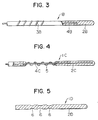
- Fig. 3 illustrates a wire 1B for opening a obstructive or stenosed region of coronary artery, according to a third embodiment.
- the wire 1B is different from the wire 1 for opening the stenosed region of coronary artery, according to the first embodiment, only in that a projection 3B is formed by a spiral element.
- the projection 3B may integrally be made of a material the same as that of a wire body 2B, or may separately be made of other materials.
- the projection 3B is made of a plastic wire or a metal wire (the projection may be made of a core 4B) having an affinity to a human body, it is necessary that both ends of the plastic wire or the metal wire are embedded in the wire body 1B so as not to be exposed.
- the spiral element 3B has a pitch of 0.5 ⁇ 5 mm.
- Fig. 4 illustrates a wire 1C for opening an obstructive or stenosed region of coronary artery, according to a fourth embodiment.
- the wire 1C is arranged such that a spiral element 5 instead of the projections is provided in concentric relation to a core 4C, and a portion of a wire body 2C, which is within a range of the spiral element 5, is resected.
- the spiral element 5 is made of a metal wire (the spiral element may be the core 4B) having an affinity to a human body, a metal wire having high resistance to electricity, a metal wire having high or strong magnetism, or a plastic wire.
- the spiral element 5 has an outer diameter which may be larger than that of the wire body 2C, or may be smaller than the latter.
- a blank wire of the spiral element 5 has a diameter of 0.1 ⁇ 1 mm, and a pitch of 0.5 ⁇ 5 mm.
- Fig. 5 illustrates a wire 1D for opening an obstructive or stenosed region of coronary artery, according to a fifth embodiment.
- the wire 1D is arranged such that a wire body 2D is made of a resilient or elastic material, and the wire 1D is provided with a plurality of ring-like grooves 6 in substitution for the projections or projection.
- Fig. 6 illustrates a wire 1E for opening an obstructive or stenosed region of coronary artery, according to a sixth embodiment.
- the wire 1E is arranged such that each of a plurality of projections 3E is in the form of a circular truncated cone.
- a wire body 2E is made of a resilient or elastic material, similarly to the fifth embodiment shown in Fig. 5.
- Fig. 7 illustrates a wire 1F for opening an obstructive or stenosed region of coronary artery, according to a seventh embodiment.
- a plurality of projections 3F are arranged only on one side of a wire body 2F, and a passage 11 through which a drug (a vasodilation drug, a thrombolytic drug or the like) is supplied, is formed in the wire body 2F.
- the passage 11 opens to the wire surface within a range of the projections 3F and at a distal end of the wire.
- a flow direction of the drug is indicated by the arrows.
- Fig. 8 illustrates a wire 1G for opening an obstructive or stenosed region of coronary artery, according to an eighth embodiment.
- the wire 1G is provided with a spiral element 5G, similarly to the fourth embodiment shown in Fig. 4.
- the wire 1G has an interior thereof which is not provided with a core, but is formed with a passage 11G.
- the passage 11G opens to a surface of a wire body 2G at a location in short of the spiral element 5G.
- the arrangement may be such that a glass fiber is inserted through the passage, and a laser beam is capable of being applied from the outside.
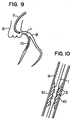
- a method of opening an obstructive or stenosed region of coronary artery, by the use of the brushing wire 1 for opening the coronary revascularization, will next be described with reference to Figs. 9 and 10.
- the revascularization is effected in the following order:
- the projections 3 on the wire 1 for coronary revascularization are located at the stenosed region and are reciprocated, whereby it is possible to cut and remove a thrombus, a hypertrophied vascular endothelium, cholesterol and the like existing in the stenosed region, to reopen blood stream to a heart or the like. Further, application of the high frequency current through the core, and application of a high frequency magnetic field through the core enable the above-described thrombus and the like to be cauterized and removed.
- the conventional balloon catheter is confined merely to enlargement of such hypertrophied section without removing the same. Accordingly, as time elapses, there is a very high probability that the lumen is depressed to cause restenosis.
- the wire 1 for coronary revascularization according to the invention, since hypertrophied sections within the artery are removed, a probability that the restenosis occurs becomes very low.
- the use of wires of various sizes it is possible to reopen a stenosed region of coronary artery to enlarge an inner diameter of the coronary artery stepwise. Since the distal end of the wire is very rich in elasticity, a complication such as injury to a coronary artery, cardiogenic shock or the like is difficult to occur so that the wire exhibits effectiveness in any coronary arteries having a small diameter.
- the elastic portion between the distal end of the wire and the projection 3 serves as a guide, it is possible to easily insert the wire into the stenosed region of coronary artery. Furthermore, since slippage of the surface of the wire body 2 is superior, there is no case where the inner wall of the coronary artery is injured. Moreover, as described above, since it is sufficient only that the wire 1 is inserted into the coronary artery and is reciprocated, operating manipulation or handling is simple and easy. Further, since the structure or construction of the wire 1 is simple, a manufacturing cost therefor is low.
- the invention is not limited to the aforesaid embodiments.
- the core like the wire 1D, 1E, 1F or 1G for coronary revascularization, according to the fifth, sixth, seventh or eighth embodiment.
- the core may reach the distal end of the wire body, or may reach a location slightly in short of the distal end of the wire body.
- each of the first ⁇ sixth embodiments in which the passage 11 or 11G is not provided it is possible to provide a passage.
- the arrangement may be such that the core and the passage are provided in the wire body in parallel relation to each other, and the passage larger than the core is formed so that the core is arranged within the passage.
- the opening location of each of the passages 11 and 11G may be anywhere within the range of the distal end of the wire, and the number of the openings (outlets) is optional.
- the projections 3, 3A, 3B, 3E and 3F and the grooves 6 into any various configurations or shapes, and both the projections and the grooves may be provided.
- the number or the projections and the grooves is optional, and the arranging locations thereof may be anywhere if the arranging locations are within the range of the distal end of the wire (they may be at the distal end or may be in the vicinity of the distal end).
- the wire for coronary revascularization has a very low probability that restenosis after operation occurs, and a complication such as a myocardial infarction, cardiogenic shock, coronary-artery injury or the like is difficult to occur. Moreover, a tendency of hemorrhage is low, and the percentage of success is very high. Further, there are produced advantages that the manufacturing cost is low, and operating manipulation or handling is simple and easy.
Abstract
Description
- The present invention relates to a wire for opening (or enlarging) a blood vessel, particularly, an obstructive or stenosed region in a coronary artery, to pass blood flow (or pass much blood flow).
- Stenosis of coronary arteries due to arteriosclerosis or the like causes myocardial infarction within a short period of time after having been broken out if the stenosis is left alone. Accordingly, urgent or emergent medical treatment is required. As a method of medical-treating (opening) the stenosed region, there have conventionally been known a method using a balloon catheter, and a method using a thrombolytic agent or drug.
- The balloon catheter is provided with a inflatable balloon at a distal end of a catheter body (refer to Japanese Utility Model Laid-Open No. SHO 61-130240 and Japanese Utility Model Laid-Open No. SHO 61-171941). The balloon catheter is inserted into a vascular stenosed region under a condition that the balloon is constricted, and fluid such as physiological saline, carbonic acid gas, a contrast medium or the like is injected into the balloon from a passage in the catheter body, to inflate the balloon. Thus, the stenosed region is enlarged, thereby opening the stenosed region.
- As the thrombolytic drug, there are known Streptokinase, Urokinase or the like. The thrombolytic drug is directly administrated into the coronary artery, dissolves a thrombus within the artery, and opens the same.
- However, the method using the balloon catheter only enlarges tissues of the artery, but does not remove the stenosed region. Accordingly, the balloon catheter method has a disadvantage that restenosis occurs in a relatively short period of time and with a high probability (for example, with a probability of 44% within three (3) months). Further, the method has also a disadvantage that a complication such as a myocardial infarction, cardiogenic shock or injury to the artery or the like occurs.
- The method using the thrombolytic drug has a tendency of hemorrhage, gastrointestinal bleeding, intracerebral bleeding or the like as a side effect, and has also a low percentage of success such as about 50%.
- In view of the above, it is an object of the invention to provide a wire for opening a stenosed region of coronary artery, which has no defects or disadvantages described above.
- The aforesaid object is achieved by the arrangement that a plurality of projections or grooves are formed within a range of a distal end of a flexible or elastic wire body, or the arrangement that a spiral body is provided in spaced relation to a distal end of a flexible or elastic wire body, and a portion of the wire body within a range of the spiral body is resected.
- In this case, the distal end of the wire body, the projections or the spiral body may be made of a high-electricity resistive material or a high magnetic material.
- Further, an elastic core may be embedded in the wire body.
- Furthermore, the wire body may be bent at a location between the distal end of the wire body and the projections, the grooves or the spiral body.
- Moreover, the arrangement may be such that a passage is formed in the wire body, and the passage is open to a surface of the wire body within a range of the distal end of the wire body so that a drug is supplied into the passage. Further, the arrangement may also be such that a glass fiber is inserted through the passage, and a laser is supplied through the wire from the outside.
- In the case of the wire for opening the stenosed region of coronary artery, according to the invention, the configuration or shape of each of the projections at a formed section is, for example, a spherical shape, a circular cylinder shape, a spiral shape, a circular truncated cone shape, or the like, and the configuration of each of the grooves is, for example, a ring-like shape, a spiral shape, a semicircular shape or the like. Further, the number of the projections and the grooves at the formed section is optional. The wire body is made of, for example, a plastic material, and the projections are made of a material identical with that of the wire body, or are made of another material such as, for example, a plastic material different from the first-mentioned plastic material, or are made of a high-electricity resistive material or a high magnetic material. The core consists of a metal wire, for example, which functions to supply high-frequency current, functions to reinforce the wire body, or functions to raise elasticity of the wire body.
- In connection with the above, in the wire for opening the stenosed region of the artery, according to the invention, the term "opening the stenosed region of the artery" includes enlargement of a stricture section in a blood vessel.
-
- Fig. 1 is a cross-sectional view of a region of a distal end of a wire for opening a stenosed region of coronary artery, according to a first embodiment of the invention;
- Fig. 2 is a cross-sectional view of a region of a distal end of a wire for opening a stenosed region of coronary artery, according to a second embodiment of the invention;
- Fig. 3 is a fragmentary cross-sectional view of a region of a distal end of a wire for opening a stenosed region of coronary artery, according to a third embodiment of the invention;
- Fig. 4 is a cross-sectional view of a region of a distal end of a wire for opening a stenosed region of coronary artery, according to a fourth embodiment of the invention;
- Fig. 5 is a cross-sectional view of a region of a distal end of a wire for opening a stenosed region of coronary artery, according to a fifth embodiment of the invention;
- Fig. 6 is a cross-sectional view of a region of a distal end of a wire for opening a stenosed region of coronary artery, according to a sixth embodiment of the invention;
- Fig. 7 is a cross-sectional view of a region of a distal end of a wire for opening a stenosed region of coronary artery, according to a seventh embodiment of the invention;
- Fig. 8 is a cross-sectional view of a region of a distal end of a wire for opening a stenosed region of coronary artery, according to an eighth embodiment of the invention;
- Fig 9 is a view showing a use of the wire for opening the stenosed region of coronary artery; and
- Fig. 10 is a fragmentary enlarged view in Fig. 9, showing a state that the stenosed region is open.
- Embodiments of the invention will be described below with reference to the drawings.
- Fig. 1 shows in a cross-sectional view a range of a distal end of an elongated wire 1 for opening an obstructive or stenosed region of coronary artery, according to a first embodiment of the invention. In Fig. 1, the
reference numeral 2 denotes a wire body; 3, projections formed on thewire body 2; and 4, a core embedded in thewire body 2. - The
wire body 2 is made of a material (flexible material) which is deformed by an external force, and is not restored to its original configuration by itself, or a material (resilient or elastic material) which, after having been deformed, is restored to its original configuration, at the time of the use of the wire 1 for opening the stenosed region of coronary artery (at the time of insertion into an artery). For example, thewire body 2 is made of a plastic material such as enamel, Teflon (trade name) or the like. Moreover, the wire body may have a coating layer such as hydrophilic polymer or the like, on the distal end portion of the wire body. Further, the wire body may have a coating layer such as tungsten-mixed polyurethane elastomer or the like, on a portion of the wire body except for the distal end portion thereof. Further, thewire body 2 is circular in transverse cross-section, and have a diameter such as 0.5 ∼ 1.2 mm. Thewire body 2 has a distal end which is so rounded as not to injure the coronary artery or the like. - Each of the
projections 3 is formed substantially into a spherical shape. In the illustrated embodiment, three projections are provided. However, the number of the projections is optional. The outer diameter of eachprojection 3 is about 0.1 ∼ 2.0 mm larger than the diameter of thewire body 2. The interval or spacing between theadjacent projections 3 is e.g. 0.5 ∼ 5.5 mm. Eachprojection 3 has an entire length of 5 ∼ 40 mm. The spacing between theprojection 3 adjacent to the distal end of thewire body 2 and the distal end thereof is e.g. 0 ∼ 50 mm, preferably, 10 ∼ 20 mm. - The core is made of a material (elastic material) which is restored to its original configuration after having been subjected to an external force and been deformed. For example, it is made of stainless steel, an alloy (nickel - titanium alloy or the like), a piano wire material, an amorphous metal, gold, a plastic material, or the like. The
core 5 has a function of reinforcing thewire body 2, or a function of increasing elasticity of thewire body 2. Thecore 5 does not reach the distal end of thewire body 2, but terminates at a location between the distal end and theprojection 3. Thecore 5 has a diameter such as 0.1 ∼ 1 mm. - Fig. 2 shows a wire 1A for opening a stenosed region of coronary artery, according to a second embodiment. The wire 1A has a plurality of
projections 3A each of which is formed into a circular cylinder shape. In order to facilitate insertion of the wire into a coronary artery which is stenosed, a portion of the wire 1A between the distal end thereof and theprojection 3A is bent through an angle α. In this case, awire body 2A is made of a material (flexible material) which is deformed by an external force, and is not restored to its original configuration by itself, or a material (resilient or elastic material) which, after having been deformed, is restored to its original configuration, at the time of the use of the wire 1A for opening the stenosed region of coronary artery. Acore 4A is made of a material (elastic material) which, after having been subjected to an external force, is deformed, and thereafter restored to its original configuration, at the use of the wire 1A for opening the stenosed region of coronary artery. Further, it is convenient if thecore 4A is made of a material which, when an operator or the like applies an external force larger than an elastic limit, to the material, can plastically be deformed into an appropriate angle α (the angle α is an optional angle equal to or less than 90°), or can be deformed into an appropriate configuration. The reason is as follows. That is, in order to facilitate insertion of the wire through the stenosed region of coronary artery, the operator can deform the portion of the distal end of the wire 1A for opening the stenosed region of the coronary artery, in accordance with parts of the stenosed region. Thecore 4A reaches a location adjacent to the distal end of thewire body 2A. - Fig. 3 illustrates a wire 1B for opening a obstructive or stenosed region of coronary artery, according to a third embodiment. The wire 1B is different from the wire 1 for opening the stenosed region of coronary artery, according to the first embodiment, only in that a projection 3B is formed by a spiral element. The projection 3B may integrally be made of a material the same as that of a wire body 2B, or may separately be made of other materials. For example, in the case where the projection 3B is made of a plastic wire or a metal wire (the projection may be made of a core 4B) having an affinity to a human body, it is necessary that both ends of the plastic wire or the metal wire are embedded in the wire body 1B so as not to be exposed. The spiral element 3B has a pitch of 0.5 ∼ 5 mm.
- Fig. 4 illustrates a wire 1C for opening an obstructive or stenosed region of coronary artery, according to a fourth embodiment. The wire 1C is arranged such that a
spiral element 5 instead of the projections is provided in concentric relation to acore 4C, and a portion of awire body 2C, which is within a range of thespiral element 5, is resected. Thespiral element 5 is made of a metal wire (the spiral element may be the core 4B) having an affinity to a human body, a metal wire having high resistance to electricity, a metal wire having high or strong magnetism, or a plastic wire. Thespiral element 5 has an outer diameter which may be larger than that of thewire body 2C, or may be smaller than the latter. A blank wire of thespiral element 5 has a diameter of 0.1 ∼ 1 mm, and a pitch of 0.5 ∼ 5 mm. - Fig. 5 illustrates a wire 1D for opening an obstructive or stenosed region of coronary artery, according to a fifth embodiment. The wire 1D is arranged such that a
wire body 2D is made of a resilient or elastic material, and the wire 1D is provided with a plurality of ring-like grooves 6 in substitution for the projections or projection. - Fig. 6 illustrates a wire 1E for opening an obstructive or stenosed region of coronary artery, according to a sixth embodiment. The wire 1E is arranged such that each of a plurality of
projections 3E is in the form of a circular truncated cone. Also in this case, awire body 2E is made of a resilient or elastic material, similarly to the fifth embodiment shown in Fig. 5. - Fig. 7 illustrates a wire 1F for opening an obstructive or stenosed region of coronary artery, according to a seventh embodiment. In the case of the wire 1F, a plurality of
projections 3F are arranged only on one side of awire body 2F, and a passage 11 through which a drug (a vasodilation drug, a thrombolytic drug or the like) is supplied, is formed in thewire body 2F. The passage 11 opens to the wire surface within a range of theprojections 3F and at a distal end of the wire. A flow direction of the drug is indicated by the arrows. - Fig. 8 illustrates a wire 1G for opening an obstructive or stenosed region of coronary artery, according to an eighth embodiment. The wire 1G is provided with a
spiral element 5G, similarly to the fourth embodiment shown in Fig. 4. However, the wire 1G has an interior thereof which is not provided with a core, but is formed with a passage 11G. The passage 11G opens to a surface of awire body 2G at a location in short of thespiral element 5G. The arrangement may be such that a glass fiber is inserted through the passage, and a laser beam is capable of being applied from the outside. - A method of opening an obstructive or stenosed region of coronary artery, by the use of the brushing wire 1 for opening the coronary revascularization, will next be described with reference to Figs. 9 and 10. The revascularization is effected in the following order:
- 1) First, an artery (not shown) is pierced, and a sheath (not shown) is held within the artery.
- 2) A heart catheter 7 is inserted into the artery, and is led to a heart 8.
- 3) A distal end of the catheter 7 is inserted into a coronary artery 9, a contrast medium is injected, and the coronary artery is examined by fluoroscopy, to confirm a
stenosed region 10. - 4) The wire 1 for coronary revascularization is inserted into the catheter 7, and is put into the coronary artery 9, and is led to the coronary-
artery stenosed region 10. At this time, since a portion of the wire between the distal end of the wire and theprojection 3 serves as a guide, it is possible to easily insert the wire 1 into the stenosed region. - 5) The wire 1 for coronary revascularization is operated to reciprocate the
projections 3 several times between a location in front of thestenosed region 10 and in rear thereof, thereby enlarging a lumen while shaving the stenosed region. At this time, the arrangement may be such that high frequency current is applied to a high resistive material through the core, and a high frequency magnetic field is applied to a ferromagnetic body, to cauterize and enlarge the stenosed region. - 6) Lastly, the wire 1 for coronary revascularization is retracted into the catheter 7 so that the catheter 7 is withdrawn from the artery.
- As described above, the
projections 3 on the wire 1 for coronary revascularization are located at the stenosed region and are reciprocated, whereby it is possible to cut and remove a thrombus, a hypertrophied vascular endothelium, cholesterol and the like existing in the stenosed region, to reopen blood stream to a heart or the like. Further, application of the high frequency current through the core, and application of a high frequency magnetic field through the core enable the above-described thrombus and the like to be cauterized and removed. - The conventional balloon catheter is confined merely to enlargement of such hypertrophied section without removing the same. Accordingly, as time elapses, there is a very high probability that the lumen is depressed to cause restenosis. However, in the case where the wire 1 for coronary revascularization, according to the invention, is used, since hypertrophied sections within the artery are removed, a probability that the restenosis occurs becomes very low. Furthermore, by the use of wires of various sizes, it is possible to reopen a stenosed region of coronary artery to enlarge an inner diameter of the coronary artery stepwise. Since the distal end of the wire is very rich in elasticity, a complication such as injury to a coronary artery, cardiogenic shock or the like is difficult to occur so that the wire exhibits effectiveness in any coronary arteries having a small diameter.
- Moreover, a tendency of hemorrhage does not occur, and the percentage of success is very high, as compared with a conventional method in which a thrombolytic drug is used.
- Further, since the elastic portion between the distal end of the wire and the
projection 3 serves as a guide, it is possible to easily insert the wire into the stenosed region of coronary artery. Furthermore, since slippage of the surface of thewire body 2 is superior, there is no case where the inner wall of the coronary artery is injured. Moreover, as described above, since it is sufficient only that the wire 1 is inserted into the coronary artery and is reciprocated, operating manipulation or handling is simple and easy. Further, since the structure or construction of the wire 1 is simple, a manufacturing cost therefor is low. - The embodiments of the invention have been described above. However, the invention is not limited to the aforesaid embodiments. For example, in the case of the wire 1, 1B or 1C for coronary revascularization, according to the first, third or fourth embodiment, it is not necessarily required to provide the core, like the wire 1D, 1E, 1F or 1G for coronary revascularization, according to the fifth, sixth, seventh or eighth embodiment. In the case where the core is provided, the core may reach the distal end of the wire body, or may reach a location slightly in short of the distal end of the wire body. Furthermore, also in the case of the wire 1, 1A, 1B, 1C and 1D for coronary revascularization, according to each of the first ∼ sixth embodiments in which the passage 11 or 11G is not provided, it is possible to provide a passage. In this case, the arrangement may be such that the core and the passage are provided in the wire body in parallel relation to each other, and the passage larger than the core is formed so that the core is arranged within the passage. Moreover, the opening location of each of the passages 11 and 11G may be anywhere within the range of the distal end of the wire, and the number of the openings (outlets) is optional. Further, it is possible to form the
projections grooves 6 into any various configurations or shapes, and both the projections and the grooves may be provided. Furthermore, the number or the projections and the grooves is optional, and the arranging locations thereof may be anywhere if the arranging locations are within the range of the distal end of the wire (they may be at the distal end or may be in the vicinity of the distal end). - As described above, the wire for coronary revascularization, according to the invention, has a very low probability that restenosis after operation occurs, and a complication such as a myocardial infarction, cardiogenic shock, coronary-artery injury or the like is difficult to occur. Moreover, a tendency of hemorrhage is low, and the percentage of success is very high. Further, there are produced advantages that the manufacturing cost is low, and operating manipulation or handling is simple and easy.
Claims (11)
- A wire for coronary revascularization, said wire being adapted to be inserted into a catheter, characterized in that a plurality of projections or grooves are formed within a range of a distal end of a flexible or elastic wire body.
- A wire for coronary revascularization, according to claim 1, characterized in that each of said projections is made of a material selected from the group consisting of a plastic material, a high-electricity resistive material and a high magnetic material.
- A wire for coronary revascularization, said wire being adapted to be inserted into a catheter, characterized in that a spiral element is provided in spaced relation to a distal end of a flexible or elastic wire body, and that a portion of the wire body within a range of the spiral element is resected.
- A wire for coronary revascularization, according to claim 3, characterized in that said spiral element is made of a material selected from the group consisting of a high-electricity resistive material and a high magnetic material.
- A wire for coronary revascularization, according to any one of claims 1 ∼ 4, characterized in that an elastic core is embedded into the wire body.
- A wire for coronary revascularization, according to any one of claims 1 ∼ 5, characterized in that the wire body is bent at a location between the distal end of the wire body and the projections, the grooves or the spiral element.
- A wire for coronary revascularization, according to any one of claims 1 ∼ 6, characterized in that a passage is formed in the wire body, and that the passage is open to a surface of the wire body within a range of the distal end of the wire body.
- A wire for coronary revascularization, according to claim 7, characterized in that said passage is a passage for supplying a drug.
- A wire for coronary revascularization, according to claim 7, characterized in that said passage is a passage through which a glass fiber is inserted, and that a laser is applicable through the glass fiber.
- A wire for coronary revascularization, said wire being adapted to be inserted into a catheter, characterized in that a core is provided within a flexible or elastic wire body, that a spiral element made of a high-electricity resistive material is arranged in spaced relation to a distal end of the wire body and in connected relation to said core, and that high frequency current is applied to the spiral element so as to be capable of heating.
- A wire for coronary revascularization, said wire being adapted to be inserted into a catheter, characterized in that a distal end of a flexible or elastic wire body is made of a high magnetic material, and that the distal end of the wire body is capable of heating by a high-frequency magnetic field.
Applications Claiming Priority (3)
| Application Number | Priority Date | Filing Date | Title |
|---|---|---|---|
| JP48657/90 | 1990-02-28 | ||
| JP4865790 | 1990-02-28 | ||
| PCT/JP1991/000272 WO1991012770A1 (en) | 1990-02-28 | 1991-02-28 | Wire for opening obstructed part of blood vessel |
Publications (3)
| Publication Number | Publication Date |
|---|---|
| EP0473790A1 true EP0473790A1 (en) | 1992-03-11 |
| EP0473790A4 EP0473790A4 (en) | 1992-08-12 |
| EP0473790B1 EP0473790B1 (en) | 1996-05-15 |
Family
ID=12809421
Family Applications (1)
| Application Number | Title | Priority Date | Filing Date |
|---|---|---|---|
| EP91904799A Expired - Lifetime EP0473790B1 (en) | 1990-02-28 | 1991-02-28 | Wire for opening obstructed part of blood vessel |
Country Status (5)
| Country | Link |
|---|---|
| EP (1) | EP0473790B1 (en) |
| AU (1) | AU655920B2 (en) |
| CA (1) | CA2053853A1 (en) |
| DE (1) | DE69119515T2 (en) |
| WO (1) | WO1991012770A1 (en) |
Cited By (7)
| Publication number | Priority date | Publication date | Assignee | Title |
|---|---|---|---|---|
| EP0597031A1 (en) * | 1991-07-26 | 1994-05-18 | Univ California | Stone expulsion stent. |
| EP0635242A1 (en) * | 1993-07-22 | 1995-01-25 | Micro Therapeutics, Inc. | Thrombectomy method and apparatus |
| WO1997027808A1 (en) * | 1996-02-02 | 1997-08-07 | Regents Of The University Of California | Clot capture coil |
| WO2001049187A1 (en) * | 2000-01-04 | 2001-07-12 | Transvascular, Inc. | Apparatus for creating a channel between adjacent body lumens |
| WO2004093695A1 (en) * | 2003-03-19 | 2004-11-04 | Boston Scientific Limited | Device for manipulating material in a tissue |
| US7785274B2 (en) | 2003-12-18 | 2010-08-31 | Terumo Kabushiki Kaisha | Guide wire |
| US7892187B2 (en) | 2002-08-23 | 2011-02-22 | Terumo Kabushiki Kaisha | Guide wire |
Families Citing this family (3)
| Publication number | Priority date | Publication date | Assignee | Title |
|---|---|---|---|---|
| JP5139184B2 (en) * | 2008-07-16 | 2013-02-06 | オリンパス株式会社 | Method for manufacturing medical device and medical device |
| DE102012106626B3 (en) | 2012-07-20 | 2013-09-26 | Krauss-Maffei Wegmann Gmbh & Co. Kg | Weapon platform, military vehicle with a weapons platform and method of operating a weapons platform |
| CN105722545B (en) | 2013-11-18 | 2020-10-20 | 皇家飞利浦有限公司 | Treatment catheter including therapeutic energy delivery |
Citations (9)
| Publication number | Priority date | Publication date | Assignee | Title |
|---|---|---|---|---|
| US2756752A (en) * | 1953-12-23 | 1956-07-31 | Scherlis Irving | Surgical instrument |
| US3635223A (en) * | 1969-12-02 | 1972-01-18 | Us Catheter & Instr Corp | Embolectomy catheter |
| US4030503A (en) * | 1975-11-05 | 1977-06-21 | Clark Iii William T | Embolectomy catheter |
| CA1124155A (en) * | 1979-08-16 | 1982-05-25 | Robert C. White | Instrument for performing endarterectomy |
| EP0218809A1 (en) * | 1985-09-19 | 1987-04-22 | Messerschmitt-Bölkow-Blohm Gesellschaft mit beschränkter Haftung | Guiding probe |
| EP0219216A1 (en) * | 1985-09-04 | 1987-04-22 | C.R. Bard, Inc. | Thermorecanalization catheter and method for use |
| EP0314896A2 (en) * | 1987-10-31 | 1989-05-10 | Angiomed Ag | Thromboembolectomy device |
| WO1989011311A1 (en) * | 1988-05-18 | 1989-11-30 | Kasevich Associates, Inc. | Microwave balloon angioplasty |
| JPH0675064A (en) * | 1990-12-11 | 1994-03-18 | Sounds Fun Inc | Animal timepiece |
Family Cites Families (7)
| Publication number | Priority date | Publication date | Assignee | Title |
|---|---|---|---|---|
| JPS52141092A (en) * | 1976-05-20 | 1977-11-25 | Nippon Zeon Co | Blood bessel catheter |
| US4548206A (en) * | 1983-07-21 | 1985-10-22 | Cook, Incorporated | Catheter wire guide with movable mandril |
| CA1266412A (en) * | 1984-10-24 | 1990-03-06 | J. Richard Spears | Method and apparatus for angioplasty |
| AU607692B2 (en) * | 1986-01-06 | 1991-03-14 | Boston Scientific Corporation Northwest Technology Center, Inc. | Transluminal microdissection device |
| CA1293663C (en) * | 1986-01-06 | 1991-12-31 | David Christopher Auth | Transluminal microdissection device |
| JPH0243397Y2 (en) * | 1986-03-27 | 1990-11-19 | ||
| JPS62231675A (en) * | 1986-03-31 | 1987-10-12 | 加藤発条株式会社 | Medical guide wire |
-
1991
- 1991-02-28 EP EP91904799A patent/EP0473790B1/en not_active Expired - Lifetime
- 1991-02-28 AU AU73308/91A patent/AU655920B2/en not_active Ceased
- 1991-02-28 WO PCT/JP1991/000272 patent/WO1991012770A1/en active IP Right Grant
- 1991-02-28 CA CA002053853A patent/CA2053853A1/en not_active Abandoned
- 1991-02-28 DE DE69119515T patent/DE69119515T2/en not_active Expired - Fee Related
Patent Citations (9)
| Publication number | Priority date | Publication date | Assignee | Title |
|---|---|---|---|---|
| US2756752A (en) * | 1953-12-23 | 1956-07-31 | Scherlis Irving | Surgical instrument |
| US3635223A (en) * | 1969-12-02 | 1972-01-18 | Us Catheter & Instr Corp | Embolectomy catheter |
| US4030503A (en) * | 1975-11-05 | 1977-06-21 | Clark Iii William T | Embolectomy catheter |
| CA1124155A (en) * | 1979-08-16 | 1982-05-25 | Robert C. White | Instrument for performing endarterectomy |
| EP0219216A1 (en) * | 1985-09-04 | 1987-04-22 | C.R. Bard, Inc. | Thermorecanalization catheter and method for use |
| EP0218809A1 (en) * | 1985-09-19 | 1987-04-22 | Messerschmitt-Bölkow-Blohm Gesellschaft mit beschränkter Haftung | Guiding probe |
| EP0314896A2 (en) * | 1987-10-31 | 1989-05-10 | Angiomed Ag | Thromboembolectomy device |
| WO1989011311A1 (en) * | 1988-05-18 | 1989-11-30 | Kasevich Associates, Inc. | Microwave balloon angioplasty |
| JPH0675064A (en) * | 1990-12-11 | 1994-03-18 | Sounds Fun Inc | Animal timepiece |
Non-Patent Citations (1)
| Title |
|---|
| See also references of WO9112770A1 * |
Cited By (23)
| Publication number | Priority date | Publication date | Assignee | Title |
|---|---|---|---|---|
| EP0597031A4 (en) * | 1991-07-26 | 1994-07-13 | Univ California | Stone expulsion stent. |
| EP0597031A1 (en) * | 1991-07-26 | 1994-05-18 | Univ California | Stone expulsion stent. |
| EP0635242A1 (en) * | 1993-07-22 | 1995-01-25 | Micro Therapeutics, Inc. | Thrombectomy method and apparatus |
| EP1642540A1 (en) * | 1996-02-02 | 2006-04-05 | The Regents Of The University Of California | Clot capture coil |
| WO1997027808A1 (en) * | 1996-02-02 | 1997-08-07 | Regents Of The University Of California | Clot capture coil |
| US5895398A (en) * | 1996-02-02 | 1999-04-20 | The Regents Of The University Of California | Method of using a clot capture coil |
| US6436112B2 (en) * | 1996-02-02 | 2002-08-20 | The Regents Of The University Of California | Method of using a clot capture coil |
| US6485497B2 (en) | 1996-02-02 | 2002-11-26 | The Regents Of The University Of California | Method of using a clot capture coil |
| US6530935B2 (en) | 1996-02-02 | 2003-03-11 | Regents Of The University Of California, The | Clot capture coil and method of using the same |
| US6692509B2 (en) | 1996-02-02 | 2004-02-17 | Regents Of The University Of California | Method of using a clot capture coil |
| US6692508B2 (en) | 1996-02-02 | 2004-02-17 | The Regents Of The University Of California | Method of using a clot capture coil |
| EP2098179A1 (en) * | 1996-02-02 | 2009-09-09 | The Regents of the University of California | Clot capture coil |
| WO2001049187A1 (en) * | 2000-01-04 | 2001-07-12 | Transvascular, Inc. | Apparatus for creating a channel between adjacent body lumens |
| US7892187B2 (en) | 2002-08-23 | 2011-02-22 | Terumo Kabushiki Kaisha | Guide wire |
| US7922673B2 (en) | 2002-08-23 | 2011-04-12 | Terumo Kabushiki Kaisha | Guide wire |
| US8109887B2 (en) | 2002-08-23 | 2012-02-07 | Terumo Kabushiki Kaisha | Guide wire |
| US8124905B2 (en) | 2002-08-23 | 2012-02-28 | Terumo Kabushiki Kaisha | Guide wire |
| US8348860B2 (en) | 2002-08-23 | 2013-01-08 | Terumo Kabushiki Kaisha | Guide wire |
| WO2004093695A1 (en) * | 2003-03-19 | 2004-11-04 | Boston Scientific Limited | Device for manipulating material in a tissue |
| US8052694B2 (en) | 2003-03-19 | 2011-11-08 | Boston Scientific Scimed, Inc. | Device for manipulating material in a tissue |
| US7785274B2 (en) | 2003-12-18 | 2010-08-31 | Terumo Kabushiki Kaisha | Guide wire |
| US8313445B2 (en) | 2003-12-18 | 2012-11-20 | Terumo Kabushiki Kaisha | Guide wire |
| US9033004B2 (en) | 2003-12-18 | 2015-05-19 | Terumo Kabushiki Kaisha | Guide wire |
Also Published As
| Publication number | Publication date |
|---|---|
| EP0473790A4 (en) | 1992-08-12 |
| EP0473790B1 (en) | 1996-05-15 |
| AU655920B2 (en) | 1995-01-19 |
| CA2053853A1 (en) | 1991-08-29 |
| DE69119515T2 (en) | 1996-11-21 |
| DE69119515D1 (en) | 1996-06-20 |
| AU7330891A (en) | 1991-09-18 |
| WO1991012770A1 (en) | 1991-09-05 |
Similar Documents
| Publication | Publication Date | Title |
|---|---|---|
| US8968350B2 (en) | Total occlusion guidewire device | |
| EP2482913B1 (en) | Cutting balloon assembly and method of manufacturing thereof | |
| JP3697553B2 (en) | Reinforced monorail balloon catheter | |
| JP4404630B2 (en) | Balloon catheter with non-stationary stent | |
| EP1092449A1 (en) | Catheter and guide wire | |
| EP1363561B1 (en) | Stent | |
| US20100249654A1 (en) | Wire guide | |
| JPH06502333A (en) | Temporary stent and its usage and manufacturing method | |
| WO1987004935A1 (en) | An intravascular stent and percutaneous insertion system | |
| JPH0663152A (en) | Catheter | |
| JP6249544B1 (en) | Catheter and balloon catheter | |
| JP4330683B2 (en) | Intraluminal insertion tool and manufacturing method thereof | |
| EP0473790A1 (en) | Wire for opening obstructed part of blood vessel | |
| JPH0519078Y2 (en) | ||
| JPH105343A (en) | Treatment instrument for lumen | |
| JP4402814B2 (en) | Medical guidewire | |
| JP2644921B2 (en) | Vascular occlusion opening wire | |
| JP2022059506A (en) | Catheter system and catheter | |
| JP4188431B2 (en) | Stent | |
| JP5618421B2 (en) | Balloon catheter | |
| JP2544260Y2 (en) | Tubular organ dilator | |
| JPH1099449A (en) | Therapeutical tool for tubular organ | |
| JP2018083076A (en) | Catheter and balloon catheter | |
| JPS6118464B2 (en) | ||
| JP2000042115A (en) | Catheter core material, catheter and balloon catheter |
Legal Events
| Date | Code | Title | Description |
|---|---|---|---|
| PUAI | Public reference made under article 153(3) epc to a published international application that has entered the european phase |
Free format text: ORIGINAL CODE: 0009012 |
|
| AK | Designated contracting states |
Kind code of ref document: A1 Designated state(s): BE CH DE DK FR GB IT LI NL |
|
| 17P | Request for examination filed |
Effective date: 19920226 |
|
| A4 | Supplementary search report drawn up and despatched |
Effective date: 19920619 |
|
| AK | Designated contracting states |
Kind code of ref document: A4 Designated state(s): BE CH DE DK FR GB IT LI NL |
|
| 17Q | First examination report despatched |
Effective date: 19930924 |
|
| GRAH | Despatch of communication of intention to grant a patent |
Free format text: ORIGINAL CODE: EPIDOS IGRA |
|
| GRAA | (expected) grant |
Free format text: ORIGINAL CODE: 0009210 |
|
| AK | Designated contracting states |
Kind code of ref document: B1 Designated state(s): DE FR GB |
|
| REF | Corresponds to: |
Ref document number: 69119515 Country of ref document: DE Date of ref document: 19960620 |
|
| ET | Fr: translation filed | ||
| PLBE | No opposition filed within time limit |
Free format text: ORIGINAL CODE: 0009261 |
|
| STAA | Information on the status of an ep patent application or granted ep patent |
Free format text: STATUS: NO OPPOSITION FILED WITHIN TIME LIMIT |
|
| 26N | No opposition filed | ||
| PGFP | Annual fee paid to national office [announced via postgrant information from national office to epo] |
Ref country code: GB Payment date: 19980128 Year of fee payment: 8 |
|
| PGFP | Annual fee paid to national office [announced via postgrant information from national office to epo] |
Ref country code: FR Payment date: 19980219 Year of fee payment: 8 |
|
| PGFP | Annual fee paid to national office [announced via postgrant information from national office to epo] |
Ref country code: DE Payment date: 19980406 Year of fee payment: 8 |
|
| PG25 | Lapsed in a contracting state [announced via postgrant information from national office to epo] |
Ref country code: GB Free format text: LAPSE BECAUSE OF NON-PAYMENT OF DUE FEES Effective date: 19990228 |
|
| GBPC | Gb: european patent ceased through non-payment of renewal fee |
Effective date: 19990228 |
|
| PG25 | Lapsed in a contracting state [announced via postgrant information from national office to epo] |
Ref country code: FR Free format text: LAPSE BECAUSE OF NON-PAYMENT OF DUE FEES Effective date: 19991029 |
|
| PG25 | Lapsed in a contracting state [announced via postgrant information from national office to epo] |
Ref country code: DE Free format text: LAPSE BECAUSE OF NON-PAYMENT OF DUE FEES Effective date: 19991201 |
|
| REG | Reference to a national code |
Ref country code: FR Ref legal event code: ST |