EP0474326A2 - Preservation housing for perishable products - Google Patents
Preservation housing for perishable products Download PDFInfo
- Publication number
- EP0474326A2 EP0474326A2 EP91250246A EP91250246A EP0474326A2 EP 0474326 A2 EP0474326 A2 EP 0474326A2 EP 91250246 A EP91250246 A EP 91250246A EP 91250246 A EP91250246 A EP 91250246A EP 0474326 A2 EP0474326 A2 EP 0474326A2
- Authority
- EP
- European Patent Office
- Prior art keywords
- vacuum
- cell
- preservation
- container
- perishable products
- Prior art date
- Legal status (The legal status is an assumption and is not a legal conclusion. Google has not performed a legal analysis and makes no representation as to the accuracy of the status listed.)
- Withdrawn
Links
Images


Classifications
-
- F—MECHANICAL ENGINEERING; LIGHTING; HEATING; WEAPONS; BLASTING
- F25—REFRIGERATION OR COOLING; COMBINED HEATING AND REFRIGERATION SYSTEMS; HEAT PUMP SYSTEMS; MANUFACTURE OR STORAGE OF ICE; LIQUEFACTION SOLIDIFICATION OF GASES
- F25D—REFRIGERATORS; COLD ROOMS; ICE-BOXES; COOLING OR FREEZING APPARATUS NOT OTHERWISE PROVIDED FOR
- F25D17/00—Arrangements for circulating cooling fluids; Arrangements for circulating gas, e.g. air, within refrigerated spaces
- F25D17/04—Arrangements for circulating cooling fluids; Arrangements for circulating gas, e.g. air, within refrigerated spaces for circulating air, e.g. by convection
- F25D17/042—Air treating means within refrigerated spaces
-
- A—HUMAN NECESSITIES
- A23—FOODS OR FOODSTUFFS; TREATMENT THEREOF, NOT COVERED BY OTHER CLASSES
- A23L—FOODS, FOODSTUFFS, OR NON-ALCOHOLIC BEVERAGES, NOT COVERED BY SUBCLASSES A21D OR A23B-A23J; THEIR PREPARATION OR TREATMENT, e.g. COOKING, MODIFICATION OF NUTRITIVE QUALITIES, PHYSICAL TREATMENT; PRESERVATION OF FOODS OR FOODSTUFFS, IN GENERAL
- A23L3/00—Preservation of foods or foodstuffs, in general, e.g. pasteurising, sterilising, specially adapted for foods or foodstuffs
- A23L3/015—Preservation of foods or foodstuffs, in general, e.g. pasteurising, sterilising, specially adapted for foods or foodstuffs by treatment with pressure variation, shock, acceleration or shear stress or cavitation
- A23L3/0155—Preservation of foods or foodstuffs, in general, e.g. pasteurising, sterilising, specially adapted for foods or foodstuffs by treatment with pressure variation, shock, acceleration or shear stress or cavitation using sub- or super-atmospheric pressures, or pressure variations transmitted by a liquid or gas
-
- A—HUMAN NECESSITIES
- A23—FOODS OR FOODSTUFFS; TREATMENT THEREOF, NOT COVERED BY OTHER CLASSES
- A23L—FOODS, FOODSTUFFS, OR NON-ALCOHOLIC BEVERAGES, NOT COVERED BY SUBCLASSES A21D OR A23B-A23J; THEIR PREPARATION OR TREATMENT, e.g. COOKING, MODIFICATION OF NUTRITIVE QUALITIES, PHYSICAL TREATMENT; PRESERVATION OF FOODS OR FOODSTUFFS, IN GENERAL
- A23L3/00—Preservation of foods or foodstuffs, in general, e.g. pasteurising, sterilising, specially adapted for foods or foodstuffs
- A23L3/36—Freezing; Subsequent thawing; Cooling
- A23L3/363—Freezing; Subsequent thawing; Cooling the materials not being transported through or in the apparatus with or without shaping, e.g. in form of powder, granules, or flakes
-
- F—MECHANICAL ENGINEERING; LIGHTING; HEATING; WEAPONS; BLASTING
- F25—REFRIGERATION OR COOLING; COMBINED HEATING AND REFRIGERATION SYSTEMS; HEAT PUMP SYSTEMS; MANUFACTURE OR STORAGE OF ICE; LIQUEFACTION SOLIDIFICATION OF GASES
- F25D—REFRIGERATORS; COLD ROOMS; ICE-BOXES; COOLING OR FREEZING APPARATUS NOT OTHERWISE PROVIDED FOR
- F25D2317/00—Details or arrangements for circulating cooling fluids; Details or arrangements for circulating gas, e.g. air, within refrigerated spaces, not provided for in other groups of this subclass
- F25D2317/04—Treating air flowing to refrigeration compartments
- F25D2317/043—Treating air flowing to refrigeration compartments by creating a vacuum in a storage compartment
Definitions
- the invention relates to a cell for the preservation of perishable products, with a vacuum system in order to produce and maintain suitable atmospheric negative pressure conditions, and with a conventional cooling system, the vacuum circuit being subordinate to the cooling circuit.
- a constant, optimal negative pressure value can be maintained by means of a differential vacuum regulator.
- the system also enables the vacuum thus obtained to be used for other additional purposes.
- Vacuum technology is currently used with various specific means on an industrial level as well as in the household.
- deformable containers are preferably used, from which the air is sucked out by means of suitable vacuum pumps or, if the products are crushable, inert or preserving gases are pumped in to compensate for the external atmospheric pressure.
- the containers are then hermetically sealed and stored in cold rooms for the medium or longer storage period.
- This procedure has the advantage that the further storage can take place at ambient temperature instead of in a cold room.
- it has the disadvantage that it cannot be used for those products which must not be exposed to the high temperatures.
- refrigeration technology enables perishable goods to be stored for different periods of time, depending on the temperature to which they are exposed.
- temperatures are just above 0 ° C, while for medium or longer times, lower temperatures are used until freezing.
- freezing has the disadvantage that the water crystallizes in the tissues, which damages the structure of the cells.
- the product When thawed, the product also loses mineral salts, water-soluble vitamins and aromas with the water, as a result of which it loses its organoleptic properties and, moreover, cannot be frozen again.
- Another disadvantage of freezing is the high energy costs for maintaining the cold and the impossibility of freezing again.
- the present invention is based on the idea of developing a system which is to combine the advantages of the effects of the vacuum with the advantages of the effects of the cold. This eliminates the need to use small containers with the advantages of a low cost system.
- the main aim of this invention is to achieve a synergistic effect by combining the known preservation techniques with a maximum of storage time and with a device which allows the creation and restoration of vacuum in a cold room, together with the possibility of introducing preservation gases therein.
- a further object of this invention is to continue the preservation under vacuum of products whose containers have been opened and thus exposed to the ambient air, since the vacuum can be re-established. This allows the use of containers of any size, from which preserved products can also be partially removed or fresh products can be added.
- An object of the present invention is to reduce the need to use small containers, the cost of which is very significant in the overall cost of the products.
- Another object of this invention is to continue the preservation under vacuum of products whose containers have been opened and thus exposed to the ambient air, since the vacuum can be restored. As a result, containers of any size can be used, from which the preserved products can be removed or additional fresh products can be filled.
- Another object of the present invention is to reduce the need for small containers since their cost is a significant burden on the total cost of the preserved products.
- This invention also strives for the possibility of using vacuum technology to create and restore negative pressure conditions in the conventional containers for storage at ambient temperature. B. for household products, and also to use the negative pressure for any other possibility and worthwhile use.
- the present invention also aims to minimize the energy costs for preservation by minimizing the need for freezing temperatures for storage in the medium or long term.
- this invention aims to use a device with which the absolute pressure can be regulated and controlled. Once an optimal pressure or negative pressure has been determined in the system, this device is intended to ensure its maintenance, within a defined sensitivity and at very reduced costs.
- the constructive solution for the cell (C), shown in Figures 2) and 3), consists of a box-like housing (1) equipped with a series of grates (2), with a bottom (3) under which the compressor group ( 11) and the container (12) of the cooling circuit, as well as the pump 21) of the vacuum system, the vacuum regulator, the solenoid valves and the electronic circuit are housed.
- the support structure (1) is equipped with suitable thermally insulated guides (4) to hold the grids, which also serve as stiffeners for the strength of the housing (1) against external pressure.
- the housing (1) has appropriate thermal insulation (5).
- the housing (1) is provided with hinges for the hermetically lockable door, which is equipped with a handle (7) and thermal insulation (8).
- the cell (C) is cooled by a conventional cooling circuit.
- This consists of a compressor (11) which feeds a condenser (13) which is in communication with the container (12) for the cooling liquid, and a series of evaporation panels (14a, 14b, 14c, 14d and 14e ), which are attached to the side walls of the housing (1), and also the ceiling and floor panels (15) and (16) of the cell (C).
- These cooling panels have a supply and a return line from and to the compressor (11).
- the cell (C) can not only be cooled, but can also be placed under vacuum with a vacuum system which consists of a pump (21) which is connected to the cell (C) through the line (22).
- This line is advantageously provided with a filter (23) at the confluence with the cell (C).
- a vacuum meter (24) is attached to the line (22) in order to measure the negative pressure prevailing in the cell (C), as well as a vacuum regulator (30) with fixed taring, and a differential vacuum regulator (36), which are further described are described in more detail and which control and compensate for the vacuum fluctuations in the cell (C).
- the vacuum system is also provided with a valve (25) to the outside.
- a connection to a valve (26) is attached to the door handle (7) in order to quickly restore the environmental pressure in the cell (C) so that the door (6) can be opened.
- the optimal vacuum conditions in a cell must be such that the maximum possible vacuum is reached, and the water freely present in the products must not boil.
- the vacuum conditions should therefore be determined in such a way that the water does not boil even at a predicted maximum summer ambient temperature of 30 ° C, which corresponds to a pressure of 40 millibars for saturated water vapor, which consequently acts as a reference pressure for the operation of the cell Vacuum can be assumed.
- Such negative pressure ratios can easily be achieved and controlled in the current state of the art, with the aid of pumps which have a best residual vacuum of 40 millibars and which are controlled by a vacuum regulator with an absolute value which switches the pump off when the desired negative pressure is reached and in the event of pressure increase again.
- the present invention seeks to provide a vacuum generation system that achieves the appropriate values for this use, generates little noise, and has a limited cost. It consists in modifying a capsule compressor, as used in cooling technology, so that it can also be used as a vacuum pump.
- the conventional capsule compressor actually reaches a maximum negative pressure of 40 millibars with the intake collector, but it is a device that is designed for a closed circuit, because otherwise there would be the possibility of seizing, since the lubricating oil lost from the drain no longer flows back into the engine .
- the change proposed here concerns the attachment of three direct-acting solenoid valves, the first between the outflow pipe (20) and the suction collector (22), the second on the suction collector (22) and the third on the outflow pipe (20) below the point of use of the first , all three controlled by a timer circuit.
- This opens the first solenoid valve for a few seconds before and after the compressor has run.
- the leaked lubricating oil is then reintroduced into the intake collector.
- the other two are only opened by the timer circuit when the first is closed.
- a collecting vessel (51) is attached to the discharge pipe (20) of the capsule compressor / vacuum pump (50), possibly with a filter (52) and a funnel (54) underneath, which is normally connected to a closed solenoid valve (55) is connected.
- the drain pipe (20) is shaped within the collecting vessel (51) in such a way that the action of the force of gravity separates the liquid oil flowing out of the compressor (50) from the air substance also exiting, falls onto the filter (52) and settles in the funnel below (54) collects, while the air-like substance flows out of the collecting vessel again via the line (20). All of this serves the purpose of separating the lubricating oil emerging from the drain, collecting it and temporarily holding it back, and then returning it to the line (22) by opening the solenoid valve (55).
- a time switch controller controls the solenoid valves (53), (55) and (56) and the pump (50).
- the timer switch (34) is fed and takes the waiting position.
- the pump (50) With the switch (58) the pump (50) is put into operation and at the same time the timer (34) is excited. This opens the solenoid valve (55) for a few seconds so that the oil that has previously exited the compressor (50) and accumulated in the collecting container (51) is drawn into the line (22), since at the same time the solenoid valves (56) and (53) are closed. In this phase, the compressor (50) turns empty, so that the motor does not have to start at full load.
- the time regulator (34) closes the solenoid valve (55) and opens the solenoid valves (53) and (56) while the compressor (50) remains in operation.
- the air is now sucked in by the line (22) and flows through the drain pipe (29), while the oil escaping from the drain flows into the collection container due to gravity and collects there.
- the electro valve on the collector which is constantly under normal pressure, can be switched off.
- the modified capsule compressor (50) works perfectly, even with an open circuit, as a vacuum pump and is able to generate a maximum vacuum of approx. 40 millibars. As described, this value is ideal when using a vacuum cell for the preservation of perishable products.
- the control and switching system is the entirety of the electrical, mechanical and pneumatic elements which are capable of creating and maintaining optimal vacuum conditions in the cell in order to maintain the products contained therein.
- a vacuum pump with the best final value of 40 millibars can be used, which is controlled by a vacuum regulator with an absolute value, or, as described above, a modified capsule compressor, which achieved a favorable negative pressure of 40 millibars during continuous operation on the intake collector.
- the compressor (50) can be attached to the cell, complete with collecting container (51), filter (52) and funnel (54) attached underneath, which opens into the solenoid valve (55), however without electrovalve (56) because it is superfluous since the line (20) is always under normal pressure.
- the timer (34), which controls the solenoid valves (53) and (55) and the pump (50), is set once and for all to the intended operating time of the pump, the operating time due to the volume of the cell (C) and the Power of the pump (50) is set.
- the time controller (34) will put the pump (50) into operation so long that the minimum residual pressure below which the pump (50) cannot go remains in cell (C), even if the pump (50) is turned off. For this solution, this pressure is about 40 millibars.
- the timer (34) can be started by closing the door (6) of the cell (C), by switching off the cooling circuit or by the differential vacuum regulator if there are pneumatic losses in the cell (C) or evaporation of the stored products results in an increase in pressure.
- the vacuum regulator (36) has the task of sensing the pressure reached in the cell (C) as soon as the vacuum pump switches off, while it is of no interest to the absolute value of this pressure; it also only functions when there is a predetermined pressure increase in cell (C), giving the impulse for starting the vacuum pump.
- the start-up is carried out by the time controller (34) with a predetermined delay, which is, however, less than that determined by the closing of the door (6) because the cell is already under vacuum.
- the pump in the cell will already have created the maximum negative pressure that it is able to generate.
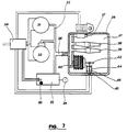
- Fig. 7 a newer solution for the differential vacuum regulator (36) is proposed, in a purely simplified schematic representation and detached from the rest of the diagram of Fig. 1, because the same device, although it solves the specific problem of the vacuum system, which one Part of the present invention, can also be used advantageously for other pneumatic purposes.
- the chamber (33) there is a pressure regulator with a fixed calibration (30), which has the task already described of notifying the time regulator (34) when the pressure moves outside the predetermined limits so that it intervenes around the compressor (31) to be switched off if the pressure value exceeds the taring, or to start the vacuum pump if the set vacuum value is not available.
- the line (35) extends from the line (22) and is connected to the direct-acting electrovalve (37), the mechanical bypass valves (38) and (39) and a pressure-sensitive element (40).
- the solenoid valve (37), the mechanical valves (38) and (39) and the pressure-sensitive element (40) are on one side with the pressure in the collector (35) and on the other side with the pressure of the cavity (41) connected in the housing (36).
- the pressure sensitive element (40) which is shown in the form of a bellows, has a lever (42) which actuates a changeover switch (45) acting on the contacts (43) and (44), while the solenoid valve (37) is operated by the time regulator (34) is connected in parallel with the active elements (31) and / or (32).
- the time regulator (34) opens the solenoid valve (37) so that the same pressure prevails in the chamber (41) as in the rest of the system.
- the compressor (31) or the pump (32) is switched off, regardless of the absolute pressure value reached, and at the same time the solenoid valve (37) closes, thus enclosing the hermetic chamber (41) identical pressure remains captured as it prevails in the rest of the system.
- a possible positive or negative pressure change in the cell (33) acts through the line (35) on the bellows (40), which expands when there is a positive change and contracts when there is a negative change, due to the difference with the constant pressure the chamber (41); this causes the lever (43) to move the changeover switch (45) against the contact (44) or contact (43).
- the mechanical valves (38) and (39) are mounted in an anti-parallel sense and calibrated to slightly higher values than those of the differentiated deflection, the moves the sensitive element (40), a safety measure which allows the inflow or outflow of air if the solenoid valve (37) should not open in time, and which has too great a pressure difference between the outer and inner walls of the sensitive element (40 ) prevents what could damage it; these valves are superfluous if the pressure-sensitive element is built sufficiently strong.
- connection of the modified capsule compressor (50) to the differential vacuum regulator (36) allows a device to be built which is capable of maintaining a residual pressure of approximately 40 to 50 millibars in a preservation cell (C) create and maintain, which is suitable to achieve the stated purposes, in particular with regard to the combination of the advantages of refrigeration and vacuum technology.
- the vacuum system is subordinate to the cooling circuit, because here it causes convective movements of the air to extract the heat from the cell, which is why the vacuum system only starts to operate when the desired low temperature has been reached.
- a further commissioning of the cooling circuit, with the cell already exposed to negative pressure, will likewise extract heat, albeit with less power, be it with the convective movements of the air, be it through the discharge by means of the cooling coils, which are attached to the grates or also by the radiation of the panels (14), (15) and (16).
- the cell of the present invention also offers the possibility of using the vacuum pump installed in the system described above also for containers which are used to store perishable products at ambient temperature, such as, for. B. Household products by working outside the cell with a device conveniently connected to the main system.
- This device makes it possible to restore the negative pressure conditions in an outside container, so that the product can be preserved at any time at ambient temperature, with the opening of the container, the removal or addition of perishable products and the reclosure of the same container.
- an indicative solution of the device (M) is described which, with a suitable connection to the vacuum system of the cell (C), allows use on containers which are outside are in the same cell (C).
- the part (60) represents a suitable branch from the suction pipe (22), which can conduct the negative pressure generated by the vacuum pump into the bell (75), with the previous interposition of an electrovalve (62) and a chamber with a float (61), whose function is described below.
- the branch (60) is connected with the interposition of the solenoid valve (62) and through the outlet from the chamber (61) with a flexible line (63) with the connection (64) which is attached to the bottom of the portable device (M).
- the line (66) is installed, which is provided with a connection (67) for the quick connection of the accessories.
- the line (66) is also connected to the solenoid valve (68), with an external connection, possibly with a filter (70) and with the connecting line (71) to the vacuum regulator (72), which is best attached so that it is in view has in order to be able to constantly control the vacuum conditions.
- the portable device (M) is completed by the bell (75), which is equipped with a head gasket (76), and with the anchors (77) and (78) so that it can be attached to the aforementioned device (M), further with the connection (79) for connection to the counter-connection (67), and with a pair of electrical contacts (80) and (81) which are inserted into counter-contacts, which are provided for this purpose on the device (M) and which communicate with the changeover switch (73).
- the electrical contacts (80) and (81) have the task of addressing the electromagnet (82) located in the bell (75), which acts on the shaft (83) which actuates the stamp (84), on which provisionally a self-adhesive Label (85) made of airtight material with the adhesive side down.
- the electromagnet (82) is firmly connected to the bell (75) by means of suitable brackets attached to the bell (75) itself, which are not shown for graphic clarity.
- the use of the device (M) provides for the temporary detachment of the supply to the cell (C) with negative pressure, which is done with a specially provided electrical circuit, which is why the previously existing negative pressure conditions prevail in the cell (C), which, however, from the vacuum meter (24) are checked, and the cooling system remains active.
- the vacuum pumps (50) or (21) automatically start up so that the vacuum is available for the new application.
- the bell (75) is placed on the cover (86) with the slide (74) of the changeover switch (73) in the rest position (3), so that any switching is excluded.
- the slide (74) When the desired vacuum is reached, which can be read on the vacuum meter (72), the slide (74) is brought into position (1) of the switch (73), which opens the solenoid valve (55) so that the pump turns empty , and the solenoid valve (62) closes, whereby the vacuum reached in the container (87) and in the line below the solenoid valve (62) is stripped.
- the electromagnet (82) is also given a pulse which sets the shaft (83) in motion in order to have the stamp (84) placed on the cover (86) where the label (85) is attached and thus the suction hole will be closed.
- the solenoid valve (68) opens, through which outside air penetrates into the lines (67) to (71) and into the bell (75), thereby equalizing the pressure, so that the cover (86) can be detached from the bell (75).
- the position (1) is also provided with a switching delay, so that when (1) is switched to (4) the contact (2) does not respond for a few seconds and the slide (74) does not release the above-described solenoid valves of position (2) starts up.
- the preserving negative pressure conditions in the container (87) can be eliminated by opening the lid (86) or simply removing or perforating the label (85) so that the same container can be opened easily.
- the process can be repeated every time one wishes to open the container to change the amount of perishable products therein; the previous conservative relationships are restored manufactured, which overcomes the current disadvantage, which makes it impossible to restore the vacuum after each opening.
- Preservative gases may also be introduced by connecting the gas container to port (69) and changing the sequence of the operations described above, e.g. h. after having created the vacuum with the slide (74) in position (2); Instead of immediately actuating the solenoid valve (82) with the slide (74) in position (1), it is first brought into position (4) to allow the gas to enter and then to position (1) to apply the label.
- Position (4) is also connected to a retarder which renders the contact (2) ineffective for a few seconds, for the same reasons as for position (1) of the contact slide (74)
- the aforementioned hermetic container (61) is advantageously installed, which is provided with a float switch, which has different tasks.
- the first task of the container (61) is to delay the creation of the vacuum in the containers (87) to allow the operator time to observe the operations.
- the second task is to prevent mistakenly sucked liquids from entering the pump in the event of a failure in the previous phase.
- the liquid collects in the container and lifts the float in the chamber (41), which moves a container and thus opens the solenoid valve (55) and closes the solenoid valve (62), with the result that a backflow is immediately interrupted.
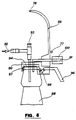
- the related device enables a further advantageous use outside the cell. It is the use of the negative pressure created by the vacuum pump for decanting or other operations which relate to the atmospheric pressure which acts on free-standing surfaces of liquids, in accordance with the design example shown in FIG. 6.
- a vertical section of the "suction closure” is shown, which consists of a suitably designed device for hermetic sealing, and is able to use the vacuum created by the vacuum pump of the known cell to act on siphons, liquids to fill or lift which small hydraulic free fall systems feed, and to perform other similar tasks.
- the container of the liquid to be decanted is deeper and cannot be moved, such as. B. buried tanks, or for liquids that are not shaken and must not be oxidized, such as cooking oils, wines etc., or hazardous liquids such as reagents, fuels etc.
- the so-called “suction closure” mainly consists of a closure device (90) to which the line (91) connected to the vacuum pump and the line (92) connected to the container to be filled are attached which has a mechanical check valve (93) built in that can be opened by hand.
- the closure device (90) also has a hermetic seal (94) and a cylindrical pin (95) which is actuated by the lever (96), which enables the closure (90) to be closed and opened by firmly attaching the cylindrical pin to the Border (97) of the container (98) is pressed, which should receive the liquid to be decanted.
- the "suction lock” (90) can also be used with the interposition of the device (M), as a replacement for the bell (75);
- said closure (90) is advantageously equipped with a retaining bracket which enables the closure device to be fastened to the device (M) by means of the anchors (77) and (78).
- the closure (90) can also be connected to the vacuum pump of the cell (C) by means of the connector (100) inserted in the connection (67) and by the changeover switch (73) and its functions (1) to (4) for suction - and transfer functions are used as described below.
- the "suction closure" (90) can also be used separately from the holder (M) in that it can be provided with a connection (100), similar to the connection (64). In this case, its operation can also be controlled from a different position and also far from the area of application.
- Fig. 6 is a suction closure for bottles to suck liquids from a lower standing container and to bring them to a higher level (98)
- the procedure is as follows :
- the suction closure (90) is placed on the opening (97) of the container (98) which is to hold the liquid to be transferred and is fastened by lifting the lever (96) and clamping the cylindrical pin (95).
- the changeover switch (73) is brought from the rest position (3) to the position (2), which closes the solenoid valve (55) and opens the solenoid valve (62) becomes; thus the air starts to be sucked out of the container (98) on the basis of the values that can be read on the vacuum meter.
- the contact (74) of the change-over switch (73) is returned to the position (3) to interrupt the process, then it may be moved to the position (4) to compensate for the pressure and to lift off the suction closure.
- a normal closure can be attached to the container (98), while the suction closure (90), with the closing of the mechanical valve (93), to another Container (98) set and the process can be repeated quickly because the suction hose attached to the connection (92) remains immersed.
- suction closure is particularly advantageous for the transfer of sensitive products such as wines, oils, etc., because the liquid is transferred from one container to another by lamellar movement, without vibrations and without contact with mechanical parts of pumps or the like, i.e. under optimal conditions to prevent undesirable side effects, such as vibration or oxidation.
- FIG. 6 An alternative proposal to the solution with the suction closure of Fig. 6 is shown in block (D) of the general scheme in Fig. 1, where the task is to suck water or other liquids from a collecting basin into which the suction line (92) is introduced to fill a utility container through line (101) using the vacuum supplied by the vacuum pump (50) already available outside the cell (C).
- the container (98) is represented by a vacuum-resistant container on which a suction closure (90) is attached, complete with line (91) which through the Solenoid valve (62 A) with three positions A), B), C), which is connected to the vacuum pump.
- the route from A) to C) is normally open, while the route B) to C) is normally closed.
- the solenoid valve (62 A) is parallel and alternative to the valve (62) and is only used if the vacuum system is used outside the cell (C) and without the intermediary of the device (M).
- the same container (98) is provided with a line (101) which is connected via the check valve (102) to the use container which is intended to hold the liquid to be filled.
- the container (98) is equipped on the inside with two float interrupters (103) and (104), the interrupter (103) operating at the lowest level of the liquid poured into the container (98) and the interrupter (104) at the highest fluid level.
- the interrupter (103) switches on and thereby closes the solenoid valve (55) and opens it Path B) - C) with the consequent closure of path A) - C) of the valve (62 A), with which the creation of the negative pressure in the container (98) begins.
- the variant described in block (D) of FIG. 1 can also be used independently of the system of the present invention, in any case by being operated by another vacuum pump, and e.g. B. can be used for emergency systems in civil defense or in other cases to pump water.
- the realization of the cell (C) also allows the use of a single capsule compressor and ensures stable preservation conditions by means of a device (36) built into it, which regulates its durability and also enables the vacuum system to be used for other advantageous purposes outside the cell.
- the realization of the cell (C) also provides for the separate use of the various parts described, for example, or even only a part, so that the individual parts can be combined individually or with one another, even in other vacuum systems.
- the cell described above and outlined, for example, for the preservation of perishable products can also be built with other structural properties.
- An example is the possibility to realize a housing (1) in which a part of the cell is intended only for vacuum operation and another part only for cooling operation or also for a cell which is used exclusively for vacuum operation, excluding the refrigeration technology. It is also possible to replace some parts, e.g. B. the electromagnet (82) with an electric motor or other mechanical system. It is also possible to build a cell without any additional equipment, by omitting the part originating from the branch (60), as it is also possible to replace the electrovalves, switches and other parts of the system, its other devices which have analog functions.
Abstract
Description
Die Erfindung bezieht sich auf eine Zelle für die Konservierung von verderblichen Produkten, mit einer Vakuumanlage, um geeignete atmosphärische Unterdrucksverhältnisse herzustellen und zu erhalten, sowie mit einer herkömmlichen Kühlanlage, wobei der Vakuumkreislauf dem Kühlumlauf untergeordnet ist.The invention relates to a cell for the preservation of perishable products, with a vacuum system in order to produce and maintain suitable atmospheric negative pressure conditions, and with a conventional cooling system, the vacuum circuit being subordinate to the cooling circuit.
Dabei besteht die Möglichkeit, für die verschiedenen Anlagen auch nur einen einzigen, dazu geeigneten hermetisch abgeschlossenen Kompressor einzusetzen.It is possible to use only a single, suitable hermetically sealed compressor for the various systems.
Weiterhin kann ein gleichbleibender optimaler Unterdruckwert durch einen Differenzialvakuumregler erhalten bleiben. Die Anlage ermöglicht außerdem den Einsatz des so erreichten Unterdrucks auch für andere zusätzliche Zwecke.Furthermore, a constant, optimal negative pressure value can be maintained by means of a differential vacuum regulator. The system also enables the vacuum thus obtained to be used for other additional purposes.
Für die Konservierung von Lebensmitteln oder sonstwie verderblichen Waren ist es zur Zeit möglich, sich der Kühl- oder der Vakuumtechnik zu bedienen. Es ist bekannt, daß die niederen Temperaturen eine Verlangsamung der Oxydationserscheinungen und der enzymatischen Reaktionen bewirken und somit die Verderblichkeit herabsetzen, während das atmosphärische Vakuum insbesondere die Bildung von Hefen und Schimmelpilzen verhindert.For the preservation of food or other perishable goods, it is currently possible to use cooling or vacuum technology. It is known that the lower temperatures slow down the oxidation phenomena and the enzymatic reactions and thus reduce the perishability, while the atmospheric vacuum in particular prevents the formation of yeasts and molds.
Die Vakuumtechnik wird zur Zeit mit verschiedenen spezifischen Mitteln auf industrieller Ebene, sowie auch im Haushalt angewandt. Auf industrieller Ebene werden vorzugsweise verformbare Behältnisse verwendet, aus denen mittels geeigneten Vakuumpumpen die Luft herausgesaugt wird oder, falls es sich um zerdrückbare Produkte handelt, Inert- oder konservierende Gase hineingepumpt werden, um den äußeren atmosphärischen Druck auszugleichen. Die Behältnisse werden dann hermetisch verschlossen und für die mittlere oder längere Aufbewahrungszeit in Kühlzellen gelagert.Vacuum technology is currently used with various specific means on an industrial level as well as in the household. At the industrial level, deformable containers are preferably used, from which the air is sucked out by means of suitable vacuum pumps or, if the products are crushable, inert or preserving gases are pumped in to compensate for the external atmospheric pressure. The containers are then hermetically sealed and stored in cold rooms for the medium or longer storage period.
Im Haushalt oder in landwirtschaftlichen Betrieben wird die Aufbewahrung unter Vakuum wie folgt gehandhabt: Die bereits mit den zu konservierenden Produkten gefüllten Behälter werden in ein 80 bis 100 °C warmes Wasserbad gelegt und dann bei dieser Temperatur verschlossen. Beim Erkalten sinkt die Wasserdampfspannung von 1013 Millibar bei Siedetemperatur auf 23 Millibar bei 20°C, womit in den Behältern ein Unterdruck oder relatives Vakuum entsteht.In the household or in farms, storage under vacuum is handled as follows: The containers already filled with the products to be preserved are placed in a water bath at 80 to 100 ° C and then sealed at this temperature. When it cools down, the water vapor voltage drops from 1013 millibars at boiling temperature to 23 millibars at 20 ° C, creating a vacuum or relative vacuum in the containers.
Dieses Vorgehen hat den Vorteil, daß die weitere Aufbewahrung bei Umwelttemperatur geschehen kann, anstatt in einer Kühlzelle. Es hat aber den Nachteil, daß es für jene Produkte nicht angewandt werden kann, welche den hohen Temperaturen nicht ausgesetzt werden dürfen.This procedure has the advantage that the further storage can take place at ambient temperature instead of in a cold room. However, it has the disadvantage that it cannot be used for those products which must not be exposed to the high temperatures.
Weiterhin hat es eine beschränkte Wirkung, weil nur der Teildruck des Wasserdampfes vermindert wird, während die Teildrücke der anderen Gase sich praktisch nicht ändern. Nicht unerwähnt bleiben sollen die Ungewißheit im Festlegen der Zeiten und die Vorbereitungsbedingungen mit der folglich hohen Anzahl von Behältern, in denen sich kein Vakuum gebildet hat, sowie die Schwierigkeit, mit den heißen Behältern umzugehen, mit der Gefahr von Brüchen und Unfällen.Furthermore, it has a limited effect because only the partial pressure of the water vapor is reduced, while the partial pressures of the other gases practically do not change. Not to be forgotten are the uncertainty in the setting of the times and the preparation conditions with the consequently high number of containers in which no vacuum has formed, as well as the difficulty in handling the hot containers, with the risk of breakages and accidents.
Aber der hauptsächlichste Nachteil aller Vakuumverpackungen liegt darin, daß es nicht möglich ist, das Vakuum wieder herzustellen, nachdem das Behältnis geöffnet worden ist. Das bedingt die Notwendigkeit, kleine Behälter zu verwenden, welche in kurzer Zeit entleert werden müssen. Daraus ergeben sich höhere Kosten, mehr Ausschuß und mehr Wegwerfmaterial.But the main disadvantage of all vacuum packaging is that it is not possible to restore the vacuum after the container has been opened. This necessitates the use of small containers which have to be emptied in a short time. This results in higher costs, more rejects and more disposable material.
Ein weiterer Nachteil der derzeitigen Vakuumtechnik ergibt sich aus den hohen Kosten der notwendigen Einrichtungen für die Messung und die Kontrolle des Unterdruckes, falls eine hohe Sensibilität verlangt wird, um die Druckverschiebungen in Grenzen weniger Millibare zu erhalten, damit optimale Konservierungsbedingungen gewährleistet sind.Another disadvantage of the current vacuum technology results from the high cost of the necessary equipment for the measurement and control of the negative pressure, if a high sensitivity is required in order to maintain the pressure shifts within a few millibars in order to ensure optimal preservation conditions.
Bekanntlich ist es mit der Kältetechnik möglich, verderbliche Güter verschieden lange Zeit aufzubewahren, je nach der Temperatur, der sie ausgesetzt werden.As is well known, refrigeration technology enables perishable goods to be stored for different periods of time, depending on the temperature to which they are exposed.
Für kürzere Zeiten handelt es sich um Temperaturen knapp über 0°C, während für mittlere oder längere Zeiten tiefere Temperaturen bis zum Einfrieren verwendet werden.For shorter times, temperatures are just above 0 ° C, while for medium or longer times, lower temperatures are used until freezing.
Das Tiefkühlen hat aber seinerseits den Nachteil, daß das Wasser in den Geweben kristallisiert, was den Aufbau der Zellen beschädigt. Beim Auftauen verliert das Produkt mit dem Wasser auch Mineralsalze, wasserlösliche Vitamine und Aromen, wodurch es seine organoleptischen Eigenschaften verliert und außerdem nicht wieder eingefroren werden kann. Ein weiterer Nachteil der Tiefkühlung sind die hohen energetischen Kosten für die Erhaltung der Kälte und die Unmöglichkeit des erneut Einfrierens.However, freezing has the disadvantage that the water crystallizes in the tissues, which damages the structure of the cells. When thawed, the product also loses mineral salts, water-soluble vitamins and aromas with the water, as a result of which it loses its organoleptic properties and, moreover, cannot be frozen again. Another disadvantage of freezing is the high energy costs for maintaining the cold and the impossibility of freezing again.
Die vorliegende Erfindung basiert auf der Idee, eine Anlage zu entwickeln, welche die Vorteile der Auswirkungen des Vakuums mit den Vorteilen der Auswirkungen der Kälte verbinden soll. Damit fällt die Notwendigkeit dahin, kleine Behälter zu verwenden, mit den Vorteilen einer Anlage mit niederem Kostenaufwand. Hauptziel dieser Erfindung ist es nämlich, eine synergetische Wirkung zu erreichen durch die Vereinigung der bekannten Konservierungstechniken mit einem Maximum an Aufbewahrungszeit sowie mit einer Einrichtung, welche die Erzeugung und Wiederherstellung von Vakuum in einer Kühlzelle zuläßt, zusammen mit der Möglichkeit, darin Konservierungsgase einzuführen.The present invention is based on the idea of developing a system which is to combine the advantages of the effects of the vacuum with the advantages of the effects of the cold. This eliminates the need to use small containers with the advantages of a low cost system. The main aim of this invention is to achieve a synergistic effect by combining the known preservation techniques with a maximum of storage time and with a device which allows the creation and restoration of vacuum in a cold room, together with the possibility of introducing preservation gases therein.
Ein weiteres Ziel dieser Erfindung ist es, die Konservierung unter Vakuum von Produkten weiterzuführen, deren Behälter geöffnet und somit der Umluft ausgesetzt worden sind, da das Vakuum erneut hergestellt werden kann. Das erlaubt den Einsatz von Behältern beliebiger Größe, aus denen konservierte Produkte auch teilweise herausgenommen oder zusätzlich frische Produkte eingefüllt werden können.A further object of this invention is to continue the preservation under vacuum of products whose containers have been opened and thus exposed to the ambient air, since the vacuum can be re-established. This allows the use of containers of any size, from which preserved products can also be partially removed or fresh products can be added.
Ein Ziel der vorliegenden Erfindung ist es, die Notwendigkeit des Einsatzes kleiner Behälter herabzusetzen, deren Kosten ganz erheblich auf den Gesamtkosten der Produkte lasten. Weiteres Ziel dieser Erfindung ist es, die Konservierung unter Vakuum von Produkten weiterzuführen, deren Behälter geöffnet und somit der Umluft ausgesetzt worden sind, da das Vakuum erneut hergestellt werden kann. Dadurch können Behälter beliebiger Größe eingesetzt werden, aus denen die konservierten Produkte herausgenommen oder zusätzliche frische Produkte eingefüllt werden können.An object of the present invention is to reduce the need to use small containers, the cost of which is very significant in the overall cost of the products. Another object of this invention is to continue the preservation under vacuum of products whose containers have been opened and thus exposed to the ambient air, since the vacuum can be restored. As a result, containers of any size can be used, from which the preserved products can be removed or additional fresh products can be filled.
Ein weiteres Ziel der vorliegenden Erfindung ist es, die Einsatznotwendigkeit kleiner Behälter herabzusetzen, da ihre Kosten ganz erheblich auf den Gesamtkosten der konservierten Produkte lasten.Another object of the present invention is to reduce the need for small containers since their cost is a significant burden on the total cost of the preserved products.
Von dieser Erfindung angestrebt ist auch die Möglichkeit, die Vakuumtechnik einzusetzen, um in den herkömmlichen Behältern zur Aufbewahrung unter Umwelttemperatur Unterdruckverhältnisse zu schaffen und wieder herzustellen, so z. B. für Haushaltprodukte, und außerdem den Unterdruck für jede andere Möglichkeit und lohnenden Einsatz zu verwenden.This invention also strives for the possibility of using vacuum technology to create and restore negative pressure conditions in the conventional containers for storage at ambient temperature. B. for household products, and also to use the negative pressure for any other possibility and worthwhile use.
Ebenso bezweckt die vorliegende Erfindung, die energetischen Kosten für die Konservierung auf ein Mindestmaß herabzusetzen, indem die Notwendigkeit von Tiefkühltemperaturen für die Aufbewahrung auf mittlere oder längere Zeit herabgesetzt wird.The present invention also aims to minimize the energy costs for preservation by minimizing the need for freezing temperatures for storage in the medium or long term.
Nicht zuletzt bezweckt diese Erfindung, eine Vorrichtung einzusetzen, mit welcher der absolute Druck reguliert und kontrolliert werden kann. Ist in der Anlage einmal ein optimaler Druck oder Unterdruck festgelegt, soll diese Vorrichtung seine Erhaltung gewährleisten, innerhalb einer festgelegten Sensibilität und mit sehr reduzierten Kosten.Last but not least, this invention aims to use a device with which the absolute pressure can be regulated and controlled. Once an optimal pressure or negative pressure has been determined in the system, this device is intended to ensure its maintenance, within a defined sensitivity and at very reduced costs.
Diese und andere Zwecke werden mit der vorliegenden Erfindung tatsächlich einwandfrei erreicht, was aus der nachfolgenden Beschreibung einer seiner als rein hinweisend und unbegrenzt zu verstehenden Konstruktionslösung hervorgeht, sowie auch aus 7 schematischen Zeichnungen.
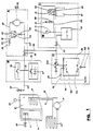
- Fig. 1) zeigt ein praktisches Schema einer vorgenannten Aufbewahrungszeile, komplett mit den Gruppen der Haupt- und und der Zusatzeinrichtungen;
- Fig. 2) auf stellt den vertikalen Schnitt einer möglichen Konstruktionsform einer genannten Zelle dar, unter Einschluß eines Zusammenbauschemas der pneumatischen Vorrichtung zur Herstellung des Vakuums und des hydraulischen Kühlkreislaufes;
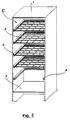
- Fig. 3) zeigt eine perspektivische Teilansicht der Tragkonstruktion der genannten Zelle;
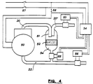
- Fig. 4) zeigt ein praktisches Schema eines Kapselkompressors mit der zweckmäßigen Abänderung, damit er auch als Vakuumpumpe eingesetzt werden kann;
- Fig. 5) zeigt einen vertikalen Schnitt einer Zusatzeinrichtung, womit die pneumatische Vorrichtung der Zelle für die Herstellung von Vakuum auch in Behältern außerhalb der Zelle eingesetzt werden kann;
- Fig. 6) zeigt eine vertikalen Schnitt einer weiteren Zusatzeinrichtung, welche an die Vakuumanlage der Zelle angebracht werden kann;
- Fig. 7) zeigt ein praktisches Schema der Kontroll- und Reguliereinrichtung für jede Abweichung von einem festgelegten Wert des absoluten Druckes.
- Fig. 1) shows a practical schematic of a storage line mentioned above, complete with the groups of the main and the additional devices;
- Fig. 2) shows the vertical section of a possible form of construction of said cell, including an assembly scheme of the pneumatic device for producing the vacuum and the hydraulic cooling circuit;
- Fig. 3) shows a partial perspective view of the support structure of said cell;
- Fig. 4) shows a practical diagram of a capsule compressor with the appropriate modification so that it can also be used as a vacuum pump;
- 5) shows a vertical section of an additional device with which the pneumatic device of the cell for the production of vacuum can also be used in containers outside the cell;
- 6) shows a vertical section of a further additional device which can be attached to the vacuum system of the cell;
- Fig. 7) shows a practical scheme of the control and regulating device for each deviation from a fixed value of the absolute pressure.
In allen Figuren sind oder verstehen sich die gleichen Einzelheiten mit der gleichen Bezugsnummer bezeichnet.In all figures, the same details are or are understood to have the same reference number.
Die konstruktive Lösung für die Zelle (C), hinweisend dargestellt in den Figuren 2) und 3), besteht aus einem kastenartigen Gehäuse (1) ausgerüstet mit einer Reihe von Rosten (2), mit einem Boden (3) unter welchem die Kompressorgruppe (11) und der Behälter (12) des Kühlkreislaufes, sowie die Pumpe 21) der Vakuumanlage, die Vakuumregler, die Elektroventile und der elektronische Schaltkreis untergebracht sind.The constructive solution for the cell (C), shown in Figures 2) and 3), consists of a box-like housing (1) equipped with a series of grates (2), with a bottom (3) under which the compressor group ( 11) and the container (12) of the cooling circuit, as well as the pump 21) of the vacuum system, the vacuum regulator, the solenoid valves and the electronic circuit are housed.
Die Tragkonstruktion (1) ist zur Halterung der Roste mit sachdienlichen thermisch isolierten Führungen (4) ausgerüstet, welche auch als Versteifung für die Festigkeit des Gehäuses (1) gegen den äußeren Druck dienen. Das Gehäuse (1) hat eine zweckmäßige thermische Isolierung (5).The support structure (1) is equipped with suitable thermally insulated guides (4) to hold the grids, which also serve as stiffeners for the strength of the housing (1) against external pressure. The housing (1) has appropriate thermal insulation (5).
Das Gehäuse (1) ist mit Scharnieren für die hermetisch abschließbare Türe versehen, welche mit einem Griff (7) und einer thermischen Isolation (8) ausgerüstet ist.The housing (1) is provided with hinges for the hermetically lockable door, which is equipped with a handle (7) and thermal insulation (8).
Die Zelle (C) wird durch einen herkömmlichen Kühlkreislauf gekühlt. Dieser besteht aus einem Kompressor (11), der einen Kondensator (13) speist, welcher mit dem Behälter (12) für die Kühlflüssigkeit in Verbindung steht, und eine Reihe von Verdampfungspaneelen (14a, 14 b, 14 c, 14 d und 14 e) versorgt, die an den Seitenwänden des Gehäuses (1) befestigt sind, sowie auch die Decken- und Bodenpaneele (15) und (16) der Zelle (C).The cell (C) is cooled by a conventional cooling circuit. This consists of a compressor (11) which feeds a condenser (13) which is in communication with the container (12) for the cooling liquid, and a series of evaporation panels (14a, 14b, 14c, 14d and 14e ), which are attached to the side walls of the housing (1), and also the ceiling and floor panels (15) and (16) of the cell (C).
Diese Kühlpaneele haben eine Zufuhr- und eine Rückfuhrleitung vom und zum Kompressor (11).These cooling panels have a supply and a return line from and to the compressor (11).
Die Zelle (C) kann nicht nur gekühlt, sondern auch mit einer Vakuumanlage, unter Vakuum gesetzt werden, die aus einer Pumpe (21) besteht, welche durch die Leitung (22) mit der Zelle (C) in Verbindung steht. Diese Leitung wird an der Einmündung in die Zelle (C) vorteilhaft mit einem Filter (23) versehen.The cell (C) can not only be cooled, but can also be placed under vacuum with a vacuum system which consists of a pump (21) which is connected to the cell (C) through the line (22). This line is advantageously provided with a filter (23) at the confluence with the cell (C).
An die Leitung (22) ist ein Vakuummeter (24) angebracht, um den in der Zelle (C) herrschenden Unterdruck zu messen, außerdem auch eine Vakuumregler (30) mit fester Tarierung, sowie ein Differential-Vakuumregler (36), welche im weiteren näher beschrieben werden und welche die Unterdruckschwankungen in der Zelle (C) kontrollieren und ausgleichen.A vacuum meter (24) is attached to the line (22) in order to measure the negative pressure prevailing in the cell (C), as well as a vacuum regulator (30) with fixed taring, and a differential vacuum regulator (36), which are further described are described in more detail and which control and compensate for the vacuum fluctuations in the cell (C).
Die Vakuumanlage ist außerdem noch mit einem Ventil (25) nach außen versehen. Auf dem Türgriff (7) ist eine Verbindung zu einem Ventil (26) angebracht, um in der Zelle (C) den Umweltdruck schnell wieder herzustellen, damit die Türe (6) geöffnet werden kann.The vacuum system is also provided with a valve (25) to the outside. A connection to a valve (26) is attached to the door handle (7) in order to quickly restore the environmental pressure in the cell (C) so that the door (6) can be opened.
Außer dem oben beschriebenen allgemeinen Teil wurden bei der Realisierung der obigen Anlage noch weitere Elemente und verschiedene Verwendungsarten in Betracht gezogen, welche besser beschrieben werden können, indem man die dargestellten Teile, insbesondere jene des allgemeinen Schemas der Fig. 1, in folgende Abschnitte einteilt:
- A) System zur Erzeugung des Vakuums;
- B) Pneumatisches Kontroll- und Schaltsystem;
- C) Verwendung außerhalb der Zelle;
- D) Weitere Verwendung außerhalb der Zelle
- A) Vacuum generation system;
- B) Pneumatic control and switching system;
- C) use outside the cell;
- D) Further use outside the cell
Die optimalen Unterdruckverhältnisse in einer Zelle, wie der oben beschriebenen, müssen derart sein, daß das maximal mögliche Vakuum erreicht wird, wobei das in den Produkten frei vorhandene Wasser nicht zum Sieden kommen darf.The optimal vacuum conditions in a cell, such as that described above, must be such that the maximum possible vacuum is reached, and the water freely present in the products must not boil.
Bei der Emittlung des maximal zu erreichenden Unterdruckes geht man vorsichtigerweise davon aus, daß die Zelle im Stande sein soll, auch nur als nicht gekühlte Vakuumzelle zu arbeiten, ohne daß sich unerwünschte Nebenwirkungen ergeben.When determining the maximum negative pressure to be reached, it is carefully assumed that the cell should be able to work even as a non-cooled vacuum cell without undesirable side effects.
Die Unterdruckverhältnisse sollen deshalb derart festgelegt werden, daß das Wasser auch bei einer vorausgesehenen maximalen Sommer-Umwelttemperatur von angenommen 30°C nicht zum Sieden kommt, was beim gesättigten Wasserdampf einem Druck von 40 Millibar entspricht, der folglich als Bezugsdruck für den Betrieb der Zelle unter Vakuum angenommen werden kann.The vacuum conditions should therefore be determined in such a way that the water does not boil even at a predicted maximum summer ambient temperature of 30 ° C, which corresponds to a pressure of 40 millibars for saturated water vapor, which consequently acts as a reference pressure for the operation of the cell Vacuum can be assumed.
Derartige Unterdruckverhältnisse können beim derzeitigen Stand der Technik leicht erreicht und kontrolliert werden, und zwar mit Hilfe von Pumpen, welche ein bestes Restvakuum von 40 Millibar aufweisen und welche von einem Vakuumregler mit absolutem Wert kontrolliert werden, der die Pumpe beim Erreichen des gewünschten Unterdrucks abstellt und im Falle der Druckerhöhung wieder anstellt.Such negative pressure ratios can easily be achieved and controlled in the current state of the art, with the aid of pumps which have a best residual vacuum of 40 millibars and which are controlled by a vacuum regulator with an absolute value which switches the pump off when the desired negative pressure is reached and in the event of pressure increase again.
Diese Lösung weist jedoch Nachteile auf, und zwar erstens die hohen Kosten des Pumpen-Vakuumregler-Systems, weiterhin der hohe Lärmpegel der Pumpe, was den Einbau in eine bewohnte Umwelt verunmöglicht.However, this solution has disadvantages, firstly the high cost of the pump vacuum regulator system and the high noise level of the pump, which makes it impossible to install it in an inhabited environment.
Mit der vorliegenden Erfindung will man ein System zur Erzeugung von Vakuum schaffen, bei welchem die geeigneten Werte für diesen Gebrauch erreicht werden, das wenig Lärm erzeugt und dessen Kosten begrenzt sind. Es besteht darin, daß ein Kapselkompressor, wie man ihn in der Kühltechnik verwendet, so abgeändert wird, daß er auch als Vakuumpumpe eingesetzt werden kann.The present invention seeks to provide a vacuum generation system that achieves the appropriate values for this use, generates little noise, and has a limited cost. It consists in modifying a capsule compressor, as used in cooling technology, so that it can also be used as a vacuum pump.
Der herkömmliche Kapselkompressor erreicht in der Tat beim Ansaugkollektor einen maximalen Unterdruck von 40 Millibar, aber es ist ein Gerät, welches für einen geschlossenen Kreislauf geschaffen ist, weil sonst die Möglichkeit des Festfressens bestünde, da das vom Ablauf verlorene Schmieröl nicht mehr in den Motor zurückfließt.The conventional capsule compressor actually reaches a maximum negative pressure of 40 millibars with the intake collector, but it is a device that is designed for a closed circuit, because otherwise there would be the possibility of seizing, since the lubricating oil lost from the drain no longer flows back into the engine .
Die hier vorgeschlagene Umänderung betrifft das Anbringen von drei direkt wirkenden Elektroventilen, das erste zwischen dem Ausflußrohr (20) und dem Ansaugkollektor (22), das zweite auf den Ansauggkollektor (22) und das dritte auf das Ausflußrohr (20) unterhalb der Einsatzstelle des ersten, alle drei mit einem Zeitschaltkreis gesteuert. Dieser öffnet das erste Elektroventil für einige Sekungen vor und nach der Laufzeit des Kompressors. Damit wird das ausgeflossene Schmieröl wieder in den Ansaugkollektor eingeführt. Die beiden anderen werden vom Zeitschaltkreis nur dann geöffnet, wenn das erste geschlossen ist.The change proposed here concerns the attachment of three direct-acting solenoid valves, the first between the outflow pipe (20) and the suction collector (22), the second on the suction collector (22) and the third on the outflow pipe (20) below the point of use of the first , all three controlled by a timer circuit. This opens the first solenoid valve for a few seconds before and after the compressor has run. The leaked lubricating oil is then reintroduced into the intake collector. The other two are only opened by the timer circuit when the first is closed.
Mit Bezug auf die Fig. 4 eingehender erklärt, wird auf dem Abflußrohr (20) des Kapselkompressors/Vakuumpumpe (50) ein Sammelgefäß (51) angebracht, eventuell mit einem Filter (52) und unterhalb befindlichem Trichter (54), welcher mit einem normalerweise geschlossenen Elektroventil (55) in Verbindung steht. Das Abflußrohr (20) ist innerhalb des Sammelgefäßes (51) solcherart geformt, daß durch die Einwirkung der Schwerkraft das vom Kompressor (50) ausfließende flüssige Öl vom ebenfalls austretenden luftförmigen Stoff getrennt wird, auf den Filter (52) fällt und sich im untenstehenden Trichter (54) sammelt, während der luftförmige Stoff über die Leitung (20) wieder aus dem Sammelgefäß ausströmt. Das alles dient dem Zweck, das aus dem Abfluß austretende Schmieröl zu trennen, zu sammeln und momentan zurückzuhalten, und es dann durch Öffnen des Elektroventils (55) wieder in die Leitung (22) zurückzuführen.Explained in more detail with reference to FIG. 4, a collecting vessel (51) is attached to the discharge pipe (20) of the capsule compressor / vacuum pump (50), possibly with a filter (52) and a funnel (54) underneath, which is normally connected to a closed solenoid valve (55) is connected. The drain pipe (20) is shaped within the collecting vessel (51) in such a way that the action of the force of gravity separates the liquid oil flowing out of the compressor (50) from the air substance also exiting, falls onto the filter (52) and settles in the funnel below (54) collects, while the air-like substance flows out of the collecting vessel again via the line (20). All of this serves the purpose of separating the lubricating oil emerging from the drain, collecting it and temporarily holding it back, and then returning it to the line (22) by opening the solenoid valve (55).
Auf der Ansaugleitung (22) und auf dem Ausflußrohr (20) sind auf der einen das Elektroventil (56), auf dem anderen das Elektroventil (53) angebracht, welche die Pumpe (50) abriegeln.On the suction line (22) and on the outflow pipe (20) on one side there is the solenoid valve (56), on the other the solenoid valve (53) which blocks the pump (50).
Ein Zeitschaltregler steuert die Elektroventile (53), (55) und (56), sowie die Pumpe (50).A time switch controller controls the solenoid valves (53), (55) and (56) and the pump (50).
Durch Einschalten des Hauptschalters (57) wird der Zeitschaltregler (34) gespeist und nimmt Wartestellung ein.By switching on the main switch (57) the timer switch (34) is fed and takes the waiting position.
Mit dem Schalter (58) wird die Pumpe (50) in Betrieb gesetzt und gleichzeitig der Zeitregler (34) angeregt. Dieser öffnet für einige Sekunden das Elektroventil (55), so daß das vorher aus dem Kompressor (50) ausgetretene und im Sammelbehälter (51) angesammelte Öl in die Leitung (22) gesogen wird, da gleichzeitig die Elektroventile (56) und (53) geschlossen sind. In dieser Phase dreht der Kompressor (50) leer, so daß der Motor nicht bei Volllast anlaufen muß.With the switch (58) the pump (50) is put into operation and at the same time the timer (34) is excited. This opens the solenoid valve (55) for a few seconds so that the oil that has previously exited the compressor (50) and accumulated in the collecting container (51) is drawn into the line (22), since at the same time the solenoid valves (56) and (53) are closed. In this phase, the compressor (50) turns empty, so that the motor does not have to start at full load.
Nach einigen Sekunden wird durch den Zeitregler (34) das Elektroventil (55) geschlossen und die Elektroventile (53) und (56) geöffnet, während der Kompressor (50) in Betrieb bleibt. Die Luft wird jetzt von der Leitung (22) angesaugt und strömt durch das Abflußrohr (29), während das aus dem Abfluß austretende Öl schwerkreftbedingt in den Sammelbehälter fließt und sich dort ansammelt.After a few seconds, the time regulator (34) closes the solenoid valve (55) and opens the solenoid valves (53) and (56) while the compressor (50) remains in operation. The air is now sucked in by the line (22) and flows through the drain pipe (29), while the oil escaping from the drain flows into the collection container due to gravity and collects there.
Ist die auf dem Zeitregler (34) eingestellte Zeit abgelaufen, stellt er die Pumpe (50) ab, schließt gleichzeitig die Elektroventile (53) und (56) und öffnet für einige Sekunden das Elekroventil (55). Dadurch wird der Druck vor und nach dem Kompressor wieder ausgeglichen und das im Sammelbehälter (51) befindliche Öl fließt in die Leitung (22), womit ein Festfressen des Kapselkompressors (50) verhindert wird.When the time set on the timer (34) has elapsed, it switches off the pump (50), simultaneously closes the solenoid valves (53) and (56) and opens the solenoid valve (55) for a few seconds. As a result, the pressure before and after the compressor is equalized again and the oil in the collecting container (51) flows into the line (22), which prevents the capsule compressor (50) from seizing up.
Weil die Elektroventile (53), (55) und (56) normalerweise geschlossen sind, bleiben die Druckverhältnisse in der Anlage, an der die Leitungen (20) und (22) angeschlossen sind, auch im Falle von Fehlschaltungen und bei eventuellem Stromausfall erhalten.Because the solenoid valves (53), (55) and (56) are normally closed, the pressure conditions in the system to which the lines (20) and (22) are connected are retained even in the event of faulty switching and a possible power failure.
Falls der Kompressor nur mit Druck oder nur mit Unterdruck arbeitet, kann das auf dem Kollektor angebrachte Elektroventil, das ständig unter Normaldruck steht, ausgeschaltet werden.If the compressor works only with pressure or only with negative pressure, the electro valve on the collector, which is constantly under normal pressure, can be switched off.
Der so abgeänderte Kapselkompressor (50) funktioniert einwandfrei, auch bei offenem Kreislauf, als Vakuumpumpe und ist im Stande, ein maximales Vakuum von ca. 40 Millibar zu erzeugen. Wie beschrieben, ist dieser Wert ideal im Einsatz einer Vakuumzelle für die Konservierung von verderblichen Produkten.The modified capsule compressor (50) works perfectly, even with an open circuit, as a vacuum pump and is able to generate a maximum vacuum of approx. 40 millibars. As described, this value is ideal when using a vacuum cell for the preservation of perishable products.
Unter Kontroll- und Schaltsystem versteht man die Gesamtheit der elektrischen, mechanischen und pneumatischen Elemente, welche dazu befähigt sind, in der Zelle optimale Vakuumverhältnisse zu schaffen und zu erhalten, um die darin befindlichen Produkte zu erhalten.The control and switching system is the entirety of the electrical, mechanical and pneumatic elements which are capable of creating and maintaining optimal vacuum conditions in the cell in order to maintain the products contained therein.
Um in der Zelle (C) einen optimalen Druck von 40 Millibar zu erreichen, kann man eine Vakuumpumpe mit bestem Endwert von 40 Millibar einsetzen, welche von einem Vakuumregler mit absolutem Wert kontrolliert wird, oder aber, wie oben beschrieben, einen abgeänderten Kapselkompressor, welcher bei Dauerbetrieb am Ansaugkollektor einen günstigsten Unterdruck von 40 Millibar erreicht.In order to achieve an optimal pressure of 40 millibars in cell (C), a vacuum pump with the best final value of 40 millibars can be used, which is controlled by a vacuum regulator with an absolute value, or, as described above, a modified capsule compressor, which achieved a favorable negative pressure of 40 millibars during continuous operation on the intake collector.
Wählt man aus Kostengründen diese letztere Lösung, so kann auf die Zelle der Kompressor (50) angebracht werden, komplett mit Sammelbehälter (51), Filter (52) und darunter angebrachtem Trichter (54), welcher in das Elektroventil (55) mündet, aber ohne Elektroventil (56), weil es überflüssig ist, da die Leitung (20) immer unter Normaldruck steht.If one chooses this latter solution for cost reasons, the compressor (50) can be attached to the cell, complete with collecting container (51), filter (52) and funnel (54) attached underneath, which opens into the solenoid valve (55), however without electrovalve (56) because it is superfluous since the line (20) is always under normal pressure.
Der Zeitregler (34), der die Elektroventile (53) und (55) und die Pumpe (50) steuert, wird ein für alle Mal auf die vorgesehene Betriebsdauer der Pumpe eingestellt, wobei die Betriebsdauer aufgrund des Volumens der Zelle (C) und die Leistung der Pumpe (50) festgelegt wird.The timer (34), which controls the solenoid valves (53) and (55) and the pump (50), is set once and for all to the intended operating time of the pump, the operating time due to the volume of the cell (C) and the Power of the pump (50) is set.
Der Zeitregler (34) wird also, einmal angesprochen, die Pumpe (50) solange in Betrieb setzen, daß der minimale Restdruck, unter den die Pumpe (50) nicht gehen kann, in der Zelle (C) bestehen bleibt, auch wenn die Pumpe (50) abgestellt wird. Für diese Lösung beträgt dieser Druck etwa 40 Millibar.Once activated, the time controller (34) will put the pump (50) into operation so long that the minimum residual pressure below which the pump (50) cannot go remains in cell (C), even if the pump (50) is turned off. For this solution, this pressure is about 40 millibars.
Der Zeitregler (34) kann durch das Schließen der Türe (6) der Zelle (C), durch das Abschalten des Kühlkreislaufes oder durch den Differential-Vakuumregler angelassen werden, falls sich in der Zelle (C) durch pneumatische Verluste des Systems oder durch Verdampfung der aufbewahrten Produkte, eine Druckerhöhung ergibt.The timer (34) can be started by closing the door (6) of the cell (C), by switching off the cooling circuit or by the differential vacuum regulator if there are pneumatic losses in the cell (C) or evaporation of the stored products results in an increase in pressure.
Derselbe Zeitregler (34) wird durch die Postition "offen" der Türe (6), durch die Postition "ein" des Kühlkompressors (11) durch die Position "offen" eines festeingestelltn Druckreglers (30) außer Betrieb gesetzt. Dieser Druckregler (30) ist auf einen angenommenen Druck von 500 Millibar eingestellt, so daß das Abschalten des Kühlkompressors, falls dieser anlaufen sollte, während die Zelle (C) im Unterdruck steht, nicht unnötigerweise die Vakuumpumpe (50) oder (21) in Betrieb setzt.The same time regulator (34) is put out of operation by the position "open" of the door (6), by the position "on" of the cooling compressor (11) by the position "open" of a fixed pressure regulator (30). This pressure regulator (30) is set to an assumed pressure of 500 millibars, so that switching off the cooling compressor, if it should start while the cell (C) is under negative pressure, does not unnecessarily operate the vacuum pump (50) or (21) puts.
Der Vakuumregler (36) hat die Aufgabe, den in der Zelle (C) erreichten Druck wahrzunehmen, sobald die Vakuumpumpe abstellt, während ihn der absolute Wert dieses Druckes nicht interessiert; er tritt auch nur in Funktion, wenn sich in der Zelle (C) eine vorher bestimmte Druckerhöhung ergibt, wobei er den Impuls für die Inbetriebsetzung der Vakuumpumpe erteilt.The vacuum regulator (36) has the task of sensing the pressure reached in the cell (C) as soon as the vacuum pump switches off, while it is of no interest to the absolute value of this pressure; it also only functions when there is a predetermined pressure increase in cell (C), giving the impulse for starting the vacuum pump.
Die Inbetriebsetzung erfolgt durch den Zeitregler (34) mit einer vorbestimmten Verzögerung, welche jedoch geringer ist als jene, der von der Schließung der Tür (6) bestimmten Zeit, weil die Zelle bereits unter Vakuum steht. Am Ende der Einschaltzeit wird die Pumpe in der Zelle bereits wieder den maximalen Unterdruck geschaffen haben, den sie zu erzeugen im Stande ist.The start-up is carried out by the time controller (34) with a predetermined delay, which is, however, less than that determined by the closing of the door (6) because the cell is already under vacuum. At the end of the switch-on time, the pump in the cell will already have created the maximum negative pressure that it is able to generate.
In Fig. 7 wird eine neuere Lösung für den Differential-Vakuumregler (36) vorgeschlagen, in einer rein vereinfachten schematischen Darstellung und losgelöst vom übrigen Schema der Fig. 1, weil die gleiche Vorrichtung, obwohl sie das spezifische Problem der Vakuumanlage löst, welche einen Teil der vorliegenden Erfindung darstellt, auch vorteilhafterweise für andere pneumatische Zwecke eingesetzt werden kann.In Fig. 7 a newer solution for the differential vacuum regulator (36) is proposed, in a purely simplified schematic representation and detached from the rest of the diagram of Fig. 1, because the same device, although it solves the specific problem of the vacuum system, which one Part of the present invention, can also be used advantageously for other pneumatic purposes.
In der vorgenannten Fig. 7 sind zwei gegensätzliche Elemente dargestellt, der Kompressor (31) und die Vakuumpumpe (32), welche miteinander und mit der Kammer (33) durch die übliche Leitung (22) verbunden sind.In the aforementioned Fig. 7, two opposite elements are shown, the compressor (31) and the vacuum pump (32), which are connected to each other and to the chamber (33) through the usual line (22).
In der Kammer (33), befindet sich ein Druckregler mit fester Eichung (30), welcher die bereits beschriebene Aufgabe hat, dem Zeitregler (34) zu melden, wenn der Druck sich außerhalb der vorbestimmten Grenzen bewegt, damit dieser einschreitet, um den Kompressor (31) abzustellen, wenn der Druckwert die Tarierung überschreitet, oder um die Vakuumpumpe in Betrieb zu setzen, wenn der eingestellte Unterdruckwert nicht vorhanden ist.In the chamber (33) there is a pressure regulator with a fixed calibration (30), which has the task already described of notifying the time regulator (34) when the pressure moves outside the predetermined limits so that it intervenes around the compressor (31) to be switched off if the pressure value exceeds the taring, or to start the vacuum pump if the set vacuum value is not available.
Von der Leitung (22) aus geht die Leitung (35), welche mit dem direkt wirkenden Elektroventil (37), den mechanischen Bypass-Ventilen (38) und (39) und einem druckempfindlichen Element (40) verbunden ist.The line (35) extends from the line (22) and is connected to the direct-acting electrovalve (37), the mechanical bypass valves (38) and (39) and a pressure-sensitive element (40).
Das Elektroventil (37), die mechanischen Ventile (38) und (39) und das druckempfindliche Element (40) sind auf der einen Seite mit dem im Kollektor (35) befindlichen Druck und auf der anderen Seite mit dem Druck des Hohlraumes (41) im Gehäuse (36) verbunden.The solenoid valve (37), the mechanical valves (38) and (39) and the pressure-sensitive element (40) are on one side with the pressure in the collector (35) and on the other side with the pressure of the cavity (41) connected in the housing (36).
Das druckempfindliche Element (40), das in Form eines Balges dargestellt wird, hat einen Hebel (42), der einen auf die Kontakte (43) und (44) wirkenden Umschalter (45) betätigt, während das Elektroventil (37) durch den Zeitregler (34) parallel mit den aktiven Elementen (31) und/oder (32) geschaltet ist.The pressure sensitive element (40), which is shown in the form of a bellows, has a lever (42) which actuates a changeover switch (45) acting on the contacts (43) and (44), while the solenoid valve (37) is operated by the time regulator (34) is connected in parallel with the active elements (31) and / or (32).
Wird eines der aktiven Elemente, der Kompressor (31) oder die Vakuumpumpe (32), in Betrieb gesetzt, bilden sich in der Zelle (33) neue Druckverhältnisse, was mit dem Mano-Vakuummeter festgestellt werden kann.If one of the active elements, the compressor (31) or the vacuum pump (32), is put into operation, new pressure conditions form in the cell (33), which can be determined with the mano-vacuum meter.
Parallel mit dem Kompressor (31) oder der Pumpe (32) geschaltet, öffnet der Zeitregler (34) das Elektroventil (37), so daß in der Kammer (41) jederzeit ein gleicher Druck herrscht, wie in der übrigen Anlage.Connected in parallel with the compressor (31) or the pump (32), the time regulator (34) opens the solenoid valve (37) so that the same pressure prevails in the chamber (41) as in the rest of the system.
Ist die im Zeitregler (34) eingestellte Zeit abgelaufen, so wird der Kompressor (31) oder die Pumpe (32) abgestellt, unabhängig vom erreichten absoluten Druckwert, gleichzeitig schließt sich das Elektroventil (37), womit in der hermetischen Kammer (41) ein identischer Druck eingefangen bleibt, wie er in der übrigen Anlage herrscht.When the time set in the time controller (34) has expired, the compressor (31) or the pump (32) is switched off, regardless of the absolute pressure value reached, and at the same time the solenoid valve (37) closes, thus enclosing the hermetic chamber (41) identical pressure remains captured as it prevails in the rest of the system.
Eine eventuelle positive oder negative Druckänderung in der Zelle (33), wirkt durch die Leitung (35) auf den Balg (40) ein, der sich bei positiver Änderung ausdehnt und sich bei negativer Änderung zusammenzieht, dies aufgrund des Unterschiedes mit dem immer gleichbleibenden Druck der Kammer (41); dadurch wird der Hebel (43) veranlaßt, den Umschalter (45) gegen den Kontakt (44) oder Kontakt (43) hin zu bewegen.A possible positive or negative pressure change in the cell (33) acts through the line (35) on the bellows (40), which expands when there is a positive change and contracts when there is a negative change, due to the difference with the constant pressure the chamber (41); this causes the lever (43) to move the changeover switch (45) against the contact (44) or contact (43).
Durch die Kontakte (43) oder (44) wird ein elektrischer Impuls zum Zeitregler (34) gesandt, der die Pumpe (32) oder den Kompressor (31) in Betrieb setzt, und zwar für eine vorher bestimmte und auf dem Zeitregler eingestellte Zeit, das Elektroventil (37) wird wieder geöffnet, damit, nachdem der Motor wieder abgestellt wurde, in der Kammer (41) der neue Druckwert erhalten bleibt.An electrical impulse is sent through the contacts (43) or (44) to the time controller (34), which starts the pump (32) or the compressor (31), for a predetermined time set on the time controller, the solenoid valve (37) is opened again so that, after the engine has been switched off again, the new pressure value is maintained in the chamber (41).
Die mechanischen Ventile (38) und (39) sind im antiparallelen Sinn montiert und auf leicht höhere Werte geeicht, als jene des differenzierten Ausschlages, der das sensible Element (40) bewegt, eine Sicherheitsmaßnahme, welche den Zu- oder Abfluß von Luft erlaubt, falls das Elektroventil (37) sich nicht rechtzeitig öffnen sollte, und die eine allzu große Druckdifferenz zwischen der Außen- und Innenwand des sensiblen Elements (40) verhindert, was dieses beschädigen könnte; diese Ventile sind überflüssig, wenn das druckempfindliche Element genügend kräftig gebaut ist.The mechanical valves (38) and (39) are mounted in an anti-parallel sense and calibrated to slightly higher values than those of the differentiated deflection, the moves the sensitive element (40), a safety measure which allows the inflow or outflow of air if the solenoid valve (37) should not open in time, and which has too great a pressure difference between the outer and inner walls of the sensitive element (40 ) prevents what could damage it; these valves are superfluous if the pressure-sensitive element is built sufficiently strong.
Eine angemessene Kombination der Eigenschaften des druckempfindlichen Elements (40) mit den Ausmaßen der Kammer (41), ergibt den zweckmäßigsten Druckunterschiedswert für den Einsatz des vorgenannten Differential-Druckreglers, sei es im Bereich der vorliegenden Konservierungsanlage, sei es in anderen Systemen für die pneumatische Druck- oder Unterdruckkontrolle.An appropriate combination of the properties of the pressure-sensitive element (40) with the dimensions of the chamber (41) results in the most appropriate pressure difference value for the use of the aforementioned differential pressure regulator, be it in the area of the present preservation system or in other systems for pneumatic pressure - or vacuum control.
Gemäß einer bevorzugten Konstruktionslösung der vorliegenden Erfindung, erlaubt die Verbindung des abgeänderten Kapselkompressor (50) mit dem Differential-Vakuumregler (36), eine Vorrichtung zu bauen, welche imstande ist, in einer Konservierungszelle (C) einen Restdruck von etwa 40 bis 50 Millibar zu schaffen und zu erhalten, der dazu geeignet ist, die angegebenen Zwecke zu erreichen, insbesondere in Bezug auf die Vereinigung der Vorteile der Kälte- und der Vakuumtechnik.According to a preferred design solution of the present invention, the connection of the modified capsule compressor (50) to the differential vacuum regulator (36) allows a device to be built which is capable of maintaining a residual pressure of approximately 40 to 50 millibars in a preservation cell (C) create and maintain, which is suitable to achieve the stated purposes, in particular with regard to the combination of the advantages of refrigeration and vacuum technology.
Es sei noch hervorgehoben, daß mit einigen geeigneten logischen Änderungen der elektrischen Schaltung, die in Bezug stehende Zelle vorteilhaft in den folgenden Fällen eingesetzt werden kann:
- a) Betrieb der Zelle nur als Vakuumzelle unter Ausschluß der Kühlanlage;
- b) Betrieb nur der Kühlanlage unter Ausschluß der Vakuumanlage;
- c) gleichzeitiger Betrieb beider Anlagen mit der der Kühlanlage untergeordneten Vakuumanlage, wie bisher beschrieben;
- d) Möglichkeit der Immission von konservierenden oder inerten Gase, für die Funktionen a) und c).
- a) Operation of the cell only as a vacuum cell excluding the cooling system;
- b) operation of the cooling system only, excluding the vacuum system;
- c) simultaneous operation of both systems with the vacuum system subordinate to the cooling system, as previously described;
- d) Possibility of immission of preserving or inert gases, for the functions a) and c).
Es wird weiterhin hervorgehoben, daß im Falle c) die Vakuumanlage dem Kühlkreislauf untergeordnet ist, weil er hier konvektive Bewegungen der Luft verursacht, um der Zelle die Wärme zu entziehen, weshalb die Vakuumanlage erst in Betrieb geht, wenn die gewollte niedere Temperatur erreicht ist. Eine weitere Inbetriebnahme des Kühlkreislaufes, bei bereits dem Unterdruck ausgesetzter Zelle, wird gleichermaßen Wärme entziehen, wenn auch mit weniger Leistung, sei es mit den konvektiven Bewegungen der Luft, sei es durch die Ableitung mittels der Kühlschlangen, welche auf den Rosten angebracht sind oder auch durch die Ausstrahlung der Paneele (14), (15) und (16).It is further emphasized that in case c) the vacuum system is subordinate to the cooling circuit, because here it causes convective movements of the air to extract the heat from the cell, which is why the vacuum system only starts to operate when the desired low temperature has been reached. A further commissioning of the cooling circuit, with the cell already exposed to negative pressure, will likewise extract heat, albeit with less power, be it with the convective movements of the air, be it through the discharge by means of the cooling coils, which are attached to the grates or also by the radiation of the panels (14), (15) and (16).
Außer dem bisher Beschriebenen, bietet die Zelle der vorliegenden Erfindung auch die Möglichkeit, die in der oben beschriebenen Anlage angebrachte Vakuumpumpe auch für Behälter einzusetzen, welche zur Aufbewahrung von verderblichen Produkten bei Umwelttemperatur dienen, wie z. B. Produkte für den Gebrauch im Haushalt, indem mit einer Einrichtung, die zweckmäßig mit der Hauptanlage verbunden ist, außerhalb der Zelle gearbeitet wird.In addition to what has been described so far, the cell of the present invention also offers the possibility of using the vacuum pump installed in the system described above also for containers which are used to store perishable products at ambient temperature, such as, for. B. Household products by working outside the cell with a device conveniently connected to the main system.
Diese Einrichtung ermöglicht, in einem außerhalb stehenden Behälter die Unterdruckverhältnisse wieder herzustellen, so daß man das Produkt jederzeit bei Umwelttemperatur konservieren kann, mit der Öffnung des Behälters, der Entnahme oder der Hinzufügung von verderblichen Produkten und dem Wiederverschluß desselben Behälters.This device makes it possible to restore the negative pressure conditions in an outside container, so that the product can be preserved at any time at ambient temperature, with the opening of the container, the removal or addition of perishable products and the reclosure of the same container.
Unter Bezugnahme auf die Fig. 5 sowie auf den Teil C des Schemas der Fig. 1 wird eine hinweisende Lösung der Einrichtung (M) beschrieben, welche mit einer geeigneten Verbindung zur Vakuumanlage der Zelle (C) den Einsatz auf Behälter erlaubt, die sich außerhalb derselben Zelle (C) befinden.With reference to FIG. 5 and to part C of the diagram of FIG. 1, an indicative solution of the device (M) is described which, with a suitable connection to the vacuum system of the cell (C), allows use on containers which are outside are in the same cell (C).
Der Teil (60) stellt eine geeignete Abzweigung vom Ansaugrohr (22) dar, welche den von der Vakuumpumpe erzeugten Unterdruck in die Glocke (75) leiten kann, mit der vorherigen Zwischenschaltung eines Elektroventils (62) und einer Kammer mit Schwimmer (61), deren Funktion im Weiteren beschrieben wird.The part (60) represents a suitable branch from the suction pipe (22), which can conduct the negative pressure generated by the vacuum pump into the bell (75), with the previous interposition of an electrovalve (62) and a chamber with a float (61), whose function is described below.
Die Abzweigung (60) wird unter Zwischenschaltung des Elektroventils (62) und durch den Austritt aus der Kammer (61) mit einer flexiblen Leitung (63) mit dem Anschluß (64) verbunden, welcher am Boden der tragbaren Einrichtung (M) angebracht ist.The branch (60) is connected with the interposition of the solenoid valve (62) and through the outlet from the chamber (61) with a flexible line (63) with the connection (64) which is attached to the bottom of the portable device (M).
Im Boden (65) ist die Leitung (66) eingebaut, die mit einem Anschluß (67) versehen ist, für den Schnellanschluß der Zubehörteile. Die Leitung (66) ist außerdem mit dem Elektroventil (68) verbunden, mit äußerem Anschluß, eventuell mit Filter (70) und mit der Verbindungsleitung (71) zum Vakuumregler (72), welcher am besten so angebracht wird, daß man ihn im Blick hat, um die Unterdruckverhältnisse ständig kontrollieren zu können.In the bottom (65) the line (66) is installed, which is provided with a connection (67) for the quick connection of the accessories. The line (66) is also connected to the solenoid valve (68), with an external connection, possibly with a filter (70) and with the connecting line (71) to the vacuum regulator (72), which is best attached so that it is in view has in order to be able to constantly control the vacuum conditions.
Auf dem Handgriff der tragbaren Einrichtung (M) ist ein Umschalter (73) angebracht, der vier elektrische Positionen für einen Schaltweg hat und in welchem sich ein Schieber befindet, der einen beweglichen Kontakt (74) hat.On the handle of the portable device (M) there is a changeover switch (73) which has four electrical positions for a switching path and in which there is a slide which has a movable contact (74).
Die tragbare Einrichtung (M) wird durch die Glocke (75) vervollständigt, welche mit einer Kopfdichtung (76) ausgerüstet ist, sowie mit den Verankerungen (77) und (78), damit sie an der vorgenannten Einrichtung (M) befestigt werden kann, weiterhin mit dem Anschluß (79) für die Verbindung mit dem Gegenanschluß (67), und mit einem Paar elektrischer Kontakte (80) und (81), welche in Gegenkontakte eigefügt werden, die eigens dafür auf der Einrichtung (M) vorgesehen sind und die mit dem Umschalter (73) in Verbindung stehen.The portable device (M) is completed by the bell (75), which is equipped with a head gasket (76), and with the anchors (77) and (78) so that it can be attached to the aforementioned device (M), further with the connection (79) for connection to the counter-connection (67), and with a pair of electrical contacts (80) and (81) which are inserted into counter-contacts, which are provided for this purpose on the device (M) and which communicate with the changeover switch (73).
Die elektrischen Kontakte (80) und (81) haben die Aufgabe, den in der Glocke (75) befindlichen Elektromagneten (82) anzusprechen, der auf die Welle (83) einwirkt, die den Stempel (84) betätigt, auf welchem provisorisch ein selbstklebendes Etikett (85) aus luftdichtem Material mit der Klebeseite nach unten angebracht ist.The electrical contacts (80) and (81) have the task of addressing the electromagnet (82) located in the bell (75), which acts on the shaft (83) which actuates the stamp (84), on which provisionally a self-adhesive Label (85) made of airtight material with the adhesive side down.
Der Elektromagnet (82) ist mit der Glocke (75) fest verbunden mittels geeigneter, an der Glocke (75) selbst angebrachter Bügel, welche der grafischen Klarheit wegen nicht dargestellt sind.The electromagnet (82) is firmly connected to the bell (75) by means of suitable brackets attached to the bell (75) itself, which are not shown for graphic clarity.
Der Einsatz der Einrichtung (M) sieht die zeitweilige Loslösung der Versorgung der Zelle (C) mit Unterdruck vor, was mit einer eigens dafür vorgesehen elektrischen Schaltung geschieht, weshalb in der Zelle (C) zeitweilig die vorher bestehenden Unterdruckverhältnisse herrschen, welche jedoch vom Vakuummeter (24) kontrolliert werden, außerdem bleibt die Kühlanlage tätig.The use of the device (M) provides for the temporary detachment of the supply to the cell (C) with negative pressure, which is done with a specially provided electrical circuit, which is why the previously existing negative pressure conditions prevail in the cell (C), which, however, from the vacuum meter (24) are checked, and the cooling system remains active.
Mit der Umschaltung der Vakuumanlage der Zelle (C) springen automatisch die Vakuumpumpen (50) oder (21) an, damit der Unterdruck für den neuen Einsatz zur Verfügung steht.When the vacuum system of cell (C) is switched over, the vacuum pumps (50) or (21) automatically start up so that the vacuum is available for the new application.
Der hermetisch abschließende Deckel (86) des Behälters (87), in dem man den Unterdruck für die Konservierung der darin eingefüllten verderblichen Produkte schaffen will, wurde im Voraus für die Luftabsaugung mit einer Bohrung versehen.The hermetically sealing lid (86) of the container (87), in which the vacuum for the preservation of the perishable products filled therein is to be created, was drilled in advance for the air extraction.
Die Glocke (75) wird auf den Deckel (86) aufgesetzt, mit dem Schieber (74) des Umschalters (73) in Ruhestellung (3), womit jegliche Schaltung ausgeschlossen ist.The bell (75) is placed on the cover (86) with the slide (74) of the changeover switch (73) in the rest position (3), so that any switching is excluded.
Bringt man den Schieber (74) in die Stellung (2), so schließt man damit das Elektroventil (55) und öffnet das Elektroventil (62), und damit beginnt das Absaugen der Luft aus dem Behälter (87).If you move the slide valve (74) to position (2), you close the solenoid valve (55) and open the solenoid valve (62), and the air is then sucked out of the container (87).
Ist der gewünschte Unterdruck erreicht, was auf dem Vakuummeter (72) abzulesen ist, bringt man den Schieber (74) in die Stellung (1) des Umschalters (73), womit man das Elektroventil (55) öffnet, so daß die Pumpe leer dreht, und das Elektroventil (62) schließt, womit der im Behälter (87) und in der Leitung unterhalb des Elektroventils (62) erreichte Unterdruck abisoliert wird.When the desired vacuum is reached, which can be read on the vacuum meter (72), the slide (74) is brought into position (1) of the switch (73), which opens the solenoid valve (55) so that the pump turns empty , and the solenoid valve (62) closes, whereby the vacuum reached in the container (87) and in the line below the solenoid valve (62) is stripped.
In der Stellung (1) wird auch dem Elektromagnet (82) ein Impuls erteilt, was die Welle (83) in Bewegung setzt, um den Stempel (84) auf den Deckel (86) auflegen zu lassen, wo das Etikett (85) angebracht und somit die Ansaugbohrung verschlosen wird.In position (1) the electromagnet (82) is also given a pulse which sets the shaft (83) in motion in order to have the stamp (84) placed on the cover (86) where the label (85) is attached and thus the suction hole will be closed.
Wird der Kontaktschieber (74) in Stellung (4) gebracht, so öffnet sich das Elektroventil (68), durch welches in die Leitungen (67) bis (71) und in die Glocke (75) Aussenluft eindringt, wodurch der Druck ausgeglichen wird, so daß der Deckel (86) von der Glocke (75) abgelöst werden kann.If the contact slide (74) is brought into position (4), the solenoid valve (68) opens, through which outside air penetrates into the lines (67) to (71) and into the bell (75), thereby equalizing the pressure, so that the cover (86) can be detached from the bell (75).
Die Stellung (1) ist auch mit einem Schaltverzögerer versehen, so daß beim Durchschalten von (1) auf (4) der Kontakt (2) für einige Sekunden nicht anspricht und der Schieber (74) nicht die oben beschriebenen Elektroventile der Stellung (2) in Betrieb setzt.The position (1) is also provided with a switching delay, so that when (1) is switched to (4) the contact (2) does not respond for a few seconds and the slide (74) does not release the above-described solenoid valves of position (2) starts up.
Die konservierenden Unterdruckverhältnisse im Behälter (87) können aufgehoben werden, indem man den Deckel (86) öffnet oder ganz einfach das Etikett (85) entfernt oder locht, so derselbe Behälter leicht geöffnet werden kann.The preserving negative pressure conditions in the container (87) can be eliminated by opening the lid (86) or simply removing or perforating the label (85) so that the same container can be opened easily.
Der Vorgang kann jedesmal wiederholt werden, wenn man den Behälter zu öffnen wünscht, um die Menge der darin befindlichen verderblichen Produkte zu verändern; die vorherigen konservierenden Verhältnisse werden wieder hergestellt, womit der derzeitige Nachteil überwunden wird, der es unmöglich macht, nach jedem Öffnen den Unterdruck wieder herzustellen.The process can be repeated every time one wishes to open the container to change the amount of perishable products therein; the previous conservative relationships are restored manufactured, which overcomes the current disadvantage, which makes it impossible to restore the vacuum after each opening.
Eventuell können auch konservierende Gase eingeführt werden, indem der Gasbehälter mit dem Anschluß (69) verbunden wird und man den Ablauf der oben beschriebenen Vorgänge ändert, d. h., nachdem man mit dem Schieber (74) in Stellung (2) den Unterdruck geschaffen hat; anstatt sofort mit dem Schieber (74) in Stellung (1) das Elektroventil (82) zu betätigen, bringt man ihn vorher in Stellung (4), um das Gas eintreten zu lassen und dann in Stellung (1), um das Etikett anzubringen.Preservative gases may also be introduced by connecting the gas container to port (69) and changing the sequence of the operations described above, e.g. h. after having created the vacuum with the slide (74) in position (2); Instead of immediately actuating the solenoid valve (82) with the slide (74) in position (1), it is first brought into position (4) to allow the gas to enter and then to position (1) to apply the label.
Auch die Stellung (4) ist mit einem Verzögerer verbunden, der den Kontakt (2) für einige Sekunden unwirksam macht, aus den gleichen Beweggründen wie für die Stellung (1) des Kontaktschiebers (74)Position (4) is also connected to a retarder which renders the contact (2) ineffective for a few seconds, for the same reasons as for position (1) of the contact slide (74)
Zwischen der Einrichtung (M) und dem Elektroventil (62) wird vorteilhaft der bereits genannte hermetische Behälter (61) eingebaut, der mit einem Schwimmschalter versehen ist, welcher verschiedene Aufgaben hat.Between the device (M) and the solenoid valve (62), the aforementioned hermetic container (61) is advantageously installed, which is provided with a float switch, which has different tasks.
Die erste Aufgabe des Behälters (61) ist die Verzögerung in der Schaffung des Unterdrucks in den Behältern (87), um dem Bedienungspersonal Zeit zu lassen, die Vorgänge zu beobachten.The first task of the container (61) is to delay the creation of the vacuum in the containers (87) to allow the operator time to observe the operations.
Die zweite Aufgabe besteht darin, den Eintritt in die Pumpe von irrtümlich angesogenen Flüssigkeiten im Falle eines Fehlers in der vorgehenden Phase zu verhindern. In diesem Falle sammelt sich nämlich die Flüssigkeit im Behälter und hebt den Schwimmer in der Kammer (41), der einen Behälter bewegt und so das Elektroventil (55) öffnet und das Elektroventil (62) schließt, womit ein Rückfließen augenblicklich unterbrochen wird.The second task is to prevent mistakenly sucked liquids from entering the pump in the event of a failure in the previous phase. In this case, namely, the liquid collects in the container and lifts the float in the chamber (41), which moves a container and thus opens the solenoid valve (55) and closes the solenoid valve (62), with the result that a backflow is immediately interrupted.
Die in Bezug stehende Einrichtung ermöglicht eine weitere vorteilhafte Verwendung außerhalb der Zelle. Es handelt sich um die Verwendung des von der Vakuumpumpe geschaffenen Unterdrucks für das Umfüllen oder andere Verrichtungen, die sich auf den atmosphärischen Druck beziehen, der auf freistehende Oberflächen von Flüssigkeiten wirkt, gemäß dem von der Fig. 6 dargestellten konstruktiven Beispiel.The related device enables a further advantageous use outside the cell. It is the use of the negative pressure created by the vacuum pump for decanting or other operations which relate to the atmospheric pressure which acts on free-standing surfaces of liquids, in accordance with the design example shown in FIG. 6.
In der Fig. 6 ist ein vertikaler Schnitt des "Saugverschlusses" dargestellt, der aus einer zweckmäßig ausgearbeiteten Vorrichtung zum hermetischen Verschließen besteht, und so imstande ist, den von der Vakuumpumpe der bekannten Zelle geschaffenen Unterdruck dazu zu benutzen, um auf Siphons einzuwirken, Flüssigkeiten umzufüllen oder zu heben, welche kleine hydraulische Freifallanlagen speisen, und um andere ähnliche Aufgaben zu erfüllen.In Fig. 6 a vertical section of the "suction closure" is shown, which consists of a suitably designed device for hermetic sealing, and is able to use the vacuum created by the vacuum pump of the known cell to act on siphons, liquids to fill or lift which small hydraulic free fall systems feed, and to perform other similar tasks.
Besondere Vorteile ergeben sich, wenn der Behälter der umzufüllenden Flüssigkeit sich tiefer befindet und nicht bewegt werden kann, wie z. B. eingegrabene Tanks, oder für Flüssigkeiten, die nicht gerüttelt werden und nicht oxydieren dürfen, wie Speiseöle, Weine usw., oder gefährliche Flüssigkeiten, wie Reagentien, Brennstoffe usw.Particular advantages arise when the container of the liquid to be decanted is deeper and cannot be moved, such as. B. buried tanks, or for liquids that are not shaken and must not be oxidized, such as cooking oils, wines etc., or hazardous liquids such as reagents, fuels etc.
Der vorgenannte "Saugverschluß" arbeitet nach dem System der theoretischen Niveaudifferenz von Flüssigkeiten in der Art, daß der atmosphärische Druck das Gewicht der zu hebenden Flüssigkeitssäule übersteigt.The aforementioned "suction closure" works according to the system of the theoretical level difference of liquids in such a way that the atmospheric pressure exceeds the weight of the liquid column to be lifted.
Mit Bezug auf die Fig. 6 besteht der sogenannte "Saugverschluß" hauptsächlich aus einer Verschlußvorrichtung (90) an der die mit der Vakuumpumpe in Verbindung stehende Leitung (91), sowie die mit dem umzufüllenden Behäler verbundenen Leitung (92), angebracht sind, auf welcher ein mechanisches Rückschlagventil (93) eingebaut ist, das von Hand geöffnet werden kann.With reference to FIG. 6, the so-called "suction closure" mainly consists of a closure device (90) to which the line (91) connected to the vacuum pump and the line (92) connected to the container to be filled are attached which has a mechanical check valve (93) built in that can be opened by hand.
Die Verschlußvorrichtung (90) hat auch eine hermetisch abschließende Dichtung (94) und einen zylindrischen Stift (95), der vom Hebel (96) betätigt wird, was das Schließen und Öffnen des Verschlusses (90) ermöglicht, indem der zylindrische Stift fest an die Umrandung (97) des Behälters (98) angedrückt wird, welcher die umzufüllende Flüssigkeit aufnehmen soll.The closure device (90) also has a hermetic seal (94) and a cylindrical pin (95) which is actuated by the lever (96), which enables the closure (90) to be closed and opened by firmly attaching the cylindrical pin to the Border (97) of the container (98) is pressed, which should receive the liquid to be decanted.
Der "Saugverschluß" (90) kann auch mit Zwischenschaltung der Einrichtung (M) verwendet werden, als Ersatz für die Glocke (75); zu diesem Zweck wird der genannte Verschluß (90) vorteilhaft mit einem Haltebügel ausgerüstet, der es ermöglicht, die Verschlußvorrichtung mittels der Verankerungen (77) und (78) an der Einrichtung (M) zu befestigen.The "suction lock" (90) can also be used with the interposition of the device (M), as a replacement for the bell (75); For this purpose, said closure (90) is advantageously equipped with a retaining bracket which enables the closure device to be fastened to the device (M) by means of the anchors (77) and (78).
Der Verschluß (90) kann auch mittels des in den Anschluß (67) gesteckten Stutzens (100) mit der Vakuumpumpe der Zelle (C) verbunden werden und durch den Umschalter (73) und seinen Funktionen (1) bis (4), für Ansaug- und Umfüllfunktionen eingesetzt werden, wie nachstehend beschrieben wird.The closure (90) can also be connected to the vacuum pump of the cell (C) by means of the connector (100) inserted in the connection (67) and by the changeover switch (73) and its functions (1) to (4) for suction - and transfer functions are used as described below.
Der "Saugverschluß" (90) kann auch getrennt von der Halterung (M) verwendet werden, indem er mit einem Anschluß (100), gleich dem Anschluß (64) versehen werden kann. In diesem Falle kann sein Betrieb auch aus einer anderen Stellung und auch fern vom Anwendungsbereich gesteuert werden.The "suction closure" (90) can also be used separately from the holder (M) in that it can be provided with a connection (100), similar to the connection (64). In this case, its operation can also be controlled from a different position and also far from the area of application.
Mit Bezug auf die konstruktive Lösung der Fig. 6, welche einen Saugverschluß für Flaschen darstellt, um Flüssigkeiten aus einem niedriger stehenden Behälter heraus zu saugen und auf ein höheres Niveau (98) zu bringen, gemäß der im Bezug stehenden Anwendung, wird wie folgt vorgegangen:
Man setzt den Saugverschluß (90) auf die Öffnung (97) des Behälters (98) auf, der die umzufüllende Flüssigkeit aufnehmen soll, und befestigt ihn, indem man den Hebel (96) hebt und den zylindrischen Stift (95) festklemmt.With reference to the constructive solution of Fig. 6, which is a suction closure for bottles to suck liquids from a lower standing container and to bring them to a higher level (98), according to the related application, the procedure is as follows :
The suction closure (90) is placed on the opening (97) of the container (98) which is to hold the liquid to be transferred and is fastened by lifting the lever (96) and clamping the cylindrical pin (95).
Nun wird der am Anschluß (92) befestigten Ansaugschlauch in den zu leerenden Behälter gesteckt, der Umschalter (73) von der Ruhestellung (3) in die Stellung (2) gebracht, womit das Elektroventil (55) geschlossen und das Elektroventil (62) geöffnet wird; somit beginnt das Ansaugen der Luft aus dem Behälter (98) aufgrund der am Vakuummeter abzulesenden Werte.Now the suction hose attached to the connection (92) is inserted into the container to be emptied, the changeover switch (73) is brought from the rest position (3) to the position (2), which closes the solenoid valve (55) and opens the solenoid valve (62) becomes; thus the air starts to be sucked out of the container (98) on the basis of the values that can be read on the vacuum meter.
Wenn der Unterdruck im Behälter (98) genügend stark ist, um den hydrostatischen Druck zu überwinden, beginnt die Flüssigkeit zu fließen, getrieben vom atmosphärischen Druck.When the vacuum in the container (98) is strong enough to overcome the hydrostatic pressure, the liquid begins to flow, driven by the atmospheric pressure.
Ist der Behälter (98) gefüllt, wird der Kontakt (74) des Umschalters (73) wieder in die Stellung (3) gebracht, um den Vorgang zu unterbrechen, dann verschiebt man ihn eventuell in die Stellung (4), um den Druck auszugleichen und um den Saugverschluß abzuheben.When the container (98) is filled, the contact (74) of the change-over switch (73) is returned to the position (3) to interrupt the process, then it may be moved to the position (4) to compensate for the pressure and to lift off the suction closure.
Auf den Behälter (98) kann ein normaler Verschluß angebracht werden, während der Saugverschluß (90), mit dem Schließen des mechanischen Ventils (93), auf einen anderen Behälter (98) gesetzt und der Vorgang schnell wiederholt werden kann, weil der am Anschluß (92) befestigte Ansaugschlauch eingetaucht bleibt.A normal closure can be attached to the container (98), while the suction closure (90), with the closing of the mechanical valve (93), to another Container (98) set and the process can be repeated quickly because the suction hose attached to the connection (92) remains immersed.
Der oben beschriebene Einsatz des "Saugverschlusses" ist ganz besonders vorteilhaft für das Umfüllen von empfindlichen Produkten, wie Weinen, Ölen, usw., weil die Übertragung der Flüssigkeit von einem Behälter zum anderen durch lamellare Bewegung erfolgt, ohne Erschütterungen und ohne Kontakt mit mechanischen Teilen von Pumpen oder mit Ähnlichem, also unter optimalen Bedingungen zur Verhinderung von unerwünschten Nebenwirkungen, wie Erschütterung oder Oxydation.The use of the "suction closure" described above is particularly advantageous for the transfer of sensitive products such as wines, oils, etc., because the liquid is transferred from one container to another by lamellar movement, without vibrations and without contact with mechanical parts of pumps or the like, i.e. under optimal conditions to prevent undesirable side effects, such as vibration or oxidation.
Ein Alternativvorschlag gegenüber der Lösung mit dem Saugverschluß der Fig. 6 ist im Block (D) des Generalschemas in Fig. 1 dargestellt, wo die Aufgabe gestellt wird, Wasser oder andere Flüssigkeiten aus einem Sammelbecken anzusaugen, in welches die Ansaugleitung (92) eingebracht wird, um einen Gebrauchsbehälter durch die Leitung (101) zu füllen, indem man den von der außerhalb der Zelle (C) befindlichen, bereits zur Verfügung stehenden Vakuumpumpe (50) gelieferten Unterdruck benutzt.An alternative proposal to the solution with the suction closure of Fig. 6 is shown in block (D) of the general scheme in Fig. 1, where the task is to suck water or other liquids from a collecting basin into which the suction line (92) is introduced to fill a utility container through line (101) using the vacuum supplied by the vacuum pump (50) already available outside the cell (C).
Im Anwendungsbeispiel von Block (D) der Fig. 1 wird der Behälter (98) von einem unterdruckfesten Behälter dargestellt, auf welchem ein Saugverschluß (90) angebracht wird, komplett mit Leitung (91), welcher durch das Elektroventil (62 A) mit drei Stellungen A), B), C), mit der Vakuumpumpe in Verbindung steht. Der Weg von A) zu C) ist normalerweise offen, während der Weg B) zu C) normalerweise geschlossen ist.In the application example of block (D) of Fig. 1, the container (98) is represented by a vacuum-resistant container on which a suction closure (90) is attached, complete with line (91) which through the Solenoid valve (62 A) with three positions A), B), C), which is connected to the vacuum pump. The route from A) to C) is normally open, while the route B) to C) is normally closed.
Das Elektroventil (62 A) ist parallel und alternativ zum Ventil (62) und wird nur dann gebraucht, wenn die Vakuumanlage außerhalb der Zelle (C) und ohne Zwischenschaltung der Einrichtung (M) gebraucht wird.The solenoid valve (62 A) is parallel and alternative to the valve (62) and is only used if the vacuum system is used outside the cell (C) and without the intermediary of the device (M).
Auf dem Verschluß (90) ist auch eine Leitung (92) angebracht, welche durch Zwischenschaltung des Rückschlagventils (93) den dichten Behälter (98) mit einem Becken in Verbindung setzt, aus welchem Wasser oder andere Flüssigkeiten entnommen werden sollen.On the closure (90) there is also a line (92) which, by interposing the check valve (93), connects the sealed container (98) to a basin from which water or other liquids are to be taken.
Derselbe Behälter (98) ist mit einer Leitung (101) versehen, welche über das Rückschlagventil (102) mit dem Gebrauchsbehälter verbunden ist, der für die Aufnahme der umzufüllenden Flüssigkeit bestimmt ist. Der Behälter (98) ist innen mit zwei Schwimmerunterbrechern (103) und (104) ausgerüstet, wobei der Unterbrecher (103) bei niedrigstem Stand der in den Behälter (98) eingegossenen Flüssigkeit und der Unterbrecher (104) bei höchstem Flüssigkeitsstand in Funktion treten.The same container (98) is provided with a line (101) which is connected via the check valve (102) to the use container which is intended to hold the liquid to be filled. The container (98) is equipped on the inside with two float interrupters (103) and (104), the interrupter (103) operating at the lowest level of the liquid poured into the container (98) and the interrupter (104) at the highest fluid level.
Wenn im Behälter (98) die Flüssigkeit den niedrigsten Stand hat, dann schaltet der Unterbrecher (103) ein und schließt dadurch das Elektroventil (55) und öffnet den Weg B) - C) mit der folgerichtigen Schließung des Weges A) - C) des Ventils (62 A), womit die Schaffung des Unterdruckes im Behälter (98) beginnt.When the liquid in the container (98) is at its lowest level, the interrupter (103) switches on and thereby closes the solenoid valve (55) and opens it Path B) - C) with the consequent closure of path A) - C) of the valve (62 A), with which the creation of the negative pressure in the container (98) begins.
Wenn die Flüssigkeit den Höchststand erreicht, schaltet der Schwimmunterdrücker (104), wodurch das Elektroventil (55) und der Weg A) - C) geöffnet werden, mit folgerichtiger Schließung des Weges B) - C) des Elektroventils (62 A).When the liquid reaches its maximum, the float suppressor (104) switches, which opens the solenoid valve (55) and path A) - C), with consequent closure of path B) - C) of the solenoid valve (62 A).
Durch das Öffnen dieses Weges werden die atmosphärischen Druckverhältnisse wieder hergestellt, was das Öffnen des Ventils (101) ermöglicht, wodurch die Flüssigkeit schwerkraftbedingt in den Gebrauchsbehälter abfließt.By opening this path, the atmospheric pressure conditions are restored, which enables the valve (101) to be opened, as a result of which the liquid flows into the use container due to gravity.
Die im Block (D) der Fig. 1 beschriebene Variante kann auch unabhängig von der Anlage der vorliegenden Erfindung eingesetzt werden, indem sie jedenfalls von einer anderen Vakuumpumpe bedient wird, und z. B. für Notfallanlagen beim Zivilschutz oder auch in anderen Fällen angewendet werden kann, um Wasser abzupumpen.The variant described in block (D) of FIG. 1 can also be used independently of the system of the present invention, in any case by being operated by another vacuum pump, and e.g. B. can be used for emergency systems in civil defense or in other cases to pump water.
Aus der bisherigen beispielsweisen Beschreibung ersieht man die synergetischen Vorteile der Konservierung durch die Vereinigung der Kältetechnik mit der ihr untergeordneten Vakuumtechnik für die Konservierung in der Zelle (C), oder auch in außerhalb der Zelle sich befindlichen Behältern von verderblichen Produkten, welche jedenfalls herausgenommen oder wieder eingefüllt werden können, ohne die Notwendigkeit, den gesamten Inhalt sofort zu gebrauchen und den Behälter wegzuwerfen, weil die Konservierungskonditionen jederzeit wiederhergestellt werden können.From the previous exemplary description one can see the synergetic advantages of the preservation by the combination of the refrigeration technology with the subordinate vacuum technology for the preservation in the cell (C), or also in containers of perishable products located outside the cell, which in any case can be removed or refilled without the need to use the entire contents immediately and to throw away the container, because the preservation conditions can be restored at any time.
Die Realisierung der Zelle (C) erlaubt außerdem, einen einzigen Kapselkompressor zu verwenden, und gewährleistet stabile Konservierungsverhältnisse durch eine in ihr eingebauten Vorrichtung (36), welche deren Beständigkeit reguliert und außerdem die Verwendung der Vakuumanlage für andere vorteilhafte Zwecke auch außerhalb der Zelle ermöglicht.The realization of the cell (C) also allows the use of a single capsule compressor and ensures stable preservation conditions by means of a device (36) built into it, which regulates its durability and also enables the vacuum system to be used for other advantageous purposes outside the cell.
Die Realisierung der Zelle (C) sieht auch den gesonderten Einsatz der verschiedenen beispielsweise beschriebenen Teile vor, oder auch nur eines Teils, so auch daß die einzelnen Teile für sich oder untereinander kombiniert werden können, und zwar auch in anderen Vakuumanlagen.The realization of the cell (C) also provides for the separate use of the various parts described, for example, or even only a part, so that the individual parts can be combined individually or with one another, even in other vacuum systems.
Alle diese Erwägungen stelle eine schematische Zusammenfassung dar, um die perfekte Eignung der Erfindung für die vorgesehenen Zwecke zu prüfen.All of these considerations represent a schematic summary to test the perfect suitability of the invention for the intended purposes.
Die oben beschriebene und beispielsweise skizzierte Zelle für die Konservierung von verderblichen Produkten, kann auch mit anderen konstruktiven Eigenschaften gebaut werden. Als Beispiel sei die Möglichkeit genannt, ein Gehäuse (1) zu realisieren, in welchem ein Teil der Zelle nur für Vakuumbetrieb vorgesehen ist und ein anderer Teil nur für den Kältebetrieb oder auch für eine Zelle, die ausschließlich für Vakuumbetrieb eingesetzt wird, unter Ausschluß der Kältetechnik. Es besteht auch die Möglichkeit, einige Teile auszutauschen, z. B. den Elektromagneten (82) mit einem elektrischen Motor oder einem anderen mechanischen System. Es ist auch möglich, eine Zelle ohne Zusatzeinrichtung zu bauen, indem der Teil, welcher von der Abzweigung (60) ausgeht, weggelassen wird, so wie es auch möglich ist, die Elektroventile, Umschalter und andere Teile der Anlage, dessen andere Vorrichtungen zu ersetzen, welche analoge Funktionen haben.The cell described above and outlined, for example, for the preservation of perishable products can also be built with other structural properties. An example is the possibility to realize a housing (1) in which a part of the cell is intended only for vacuum operation and another part only for cooling operation or also for a cell which is used exclusively for vacuum operation, excluding the refrigeration technology. It is also possible to replace some parts, e.g. B. the electromagnet (82) with an electric motor or other mechanical system. It is also possible to build a cell without any additional equipment, by omitting the part originating from the branch (60), as it is also possible to replace the electrovalves, switches and other parts of the system, its other devices which have analog functions.
Diese und andere ähnliche Änderungen verstehen sich in jedem Fall als zur Erfindung gehörend.In any case, these and other similar changes are to be considered part of the invention.
- (01)(01)
- Aufbau für die pneumatische KühlzelleStructure for the pneumatic cold room
- (02)(02)
- Roste für die ZelleGratings for the cell
- (03)(03)
- Boden für die ZelleSoil for the cell
- (04)(04)
- Thermisch isolierte Führungen für die Roste (02)Thermally insulated guides for the gratings (02)
- (05)(05)
- Thermische Isolation der ZelleThermal insulation of the cell
- (06)(06)
- Eingangstür der ZelleEntrance door to the cell
- (07)(07)
- Handgriff der Tür (06)Handle of the door (06)
- (08)(08)
- Isolierung der Tür (06)Door insulation (06)
- (09)(09)
- Passive Türfüllung (06)Passive door panel (06)
- (11)(11)
- Kompressor für den KühlumlaufCompressor for the cooling circuit
- (12)(12)
- Behälter für die KühlflüssigkeitCoolant tank
- (13)(13)
- KühlkondensatorCooling condenser
- (14)(14)
- (a), (b), (c) usw. seitliche Kühlpaneele(a), (b), (c) etc. side cooling panels
- (15)(15)
- oberes Verdampfungspaneelupper evaporation panel
- (16)(16)
- unteres Verdampfungspaneellower evaporation panel
- (17)(17)
- Zuführungsrohr der Kühlflüssigkeit zu den PaneelenCoolant liquid supply pipe to the panels
- (18)(18)
- Rückführungsrohr der Kühlflüssigkeit zum Kompressor (61)Coolant return pipe to compressor (61)
- (20)(20)
- Ausflußrohr der Pumpe (11)Pump discharge pipe (11)
- (21)(21)
- VakuumpumpeVacuum pump
- (22)(22)
- Pneumatische Verbindungsleitung zur Zelle (C)Pneumatic connection line to the cell (C)
- (23)(23)
- Filter der Verbindungsleitung (22)Connection Line Filters (22)
- (24)(24)
- Manometer-VakuummeterPressure gauge vacuum meter
- (25)(25)
- Ventil für die Verbindung nach außenValve for the connection to the outside
- (26)(26)
- Ventil zur Wiederherstellung des Druckes auf den Griff (7)Valve for restoring pressure to the handle (7)
- (30)(30)
- Unterdruck-Druckregler mit fester EichungVacuum pressure regulator with fixed calibration
- (31)(31)
- Theoretischer KompressorTheoretical compressor
- (32)(32)
- Theoretische VakuumpumpeTheoretical vacuum pump
- (33)(33)
- Kammer der Zelle (C)Chamber of the cell (C)
- (34)(34)
- ZeitschaltreglerTimer switch
- (35)(35)
- Leitung zum Differential-Vakuumregler (36)Cable to the differential vacuum regulator (36)
- (36)(36)
- Kasten des Differential-Vakuumreglers VQS-1VQS-1 differential vacuum regulator box
- (37)(37)
- Elektroventil mit direktem Einfluß für VQS-1Solenoid valve with direct influence for VQS-1
- (38)(38)
- Mechanisches By-pass-VentilMechanical by-pass valve
- (39)(39)
- Mechanisches By-pass-VentilMechanical by-pass valve
- (40)(40)
- Sensibles BalgelementSensitive bellows element
- (41)(41)
- Hermetisch abschließbare Kammer des Kastens (36)Hermetically lockable chamber of the box (36)
- (42)(42)
- Hebel des Balges (40)Bellows Lever (40)
- (43)(43)
- Elektrischer Kontakt für den MindestdruckElectrical contact for the minimum pressure
- (44)(44)
- Elektrischer Kontakt für den HöchstdruckElectrical contact for maximum pressure
- (45)(45)
- Umschalter für die Kontakte (43) und (44)Switch for contacts (43) and (44)
- (50)(50)
- Vakuumkapsel/KapselkompressorVacuum capsule / capsule compressor
- (51)(51)
- SchmierölsammelgefäßLube oil reservoir
- (52)(52)
- Filter für das SchmierölsammelgefäßFilters for the lubricating oil reservoir
- (53)(53)
- Elektroventil auf dem Ausflußrohr (20)Electro valve on the outlet pipe (20)
- (54)(54)
- Ölsammeltrichter für Ölbehälter (51)Oil collecting funnels for oil tanks (51)
- (55)(55)
- Elektroventil zur Entleerung des Ölbehälters (51)Electro valve for emptying the oil container (51)
- (56)(56)
- Elektroventil auf der Ansaugleitung (22)Solenoid valve on the suction line (22)
- (57)(57)
- Elektrischer HauptschalterElectrical main switch
- (58)(58)
- Schalter für Zeitregler (34)Timer switch (34)
- (60)(60)
- Abzweigung von der Ansaugleitung (22)Branch from the intake pipe (22)
- (61)(61)
- Kammer mit SchwimmerschalterChamber with float switch
- (62)(62)
- Elektroventil der Abzweigung (60)Branch solenoid valve (60)
- (63)(63)
- Elastische VerbindungElastic connection
- (64)(64)
- Verbindungsstück für das Gerät (M)Device connector (M)
- (65)(65)
- Deckel des Gerätes (M)Device cover (M)
- (66)(66)
- Zuführleitung zur Glocke (75)Supply line to the bell (75)
- (67)(67)
- Anschluß an die Glocke (75)Connection to the bell (75)
- (68)(68)
- Elektroventil zur Verbindung nach außenSolenoid valve for connection to the outside
- (69)(69)
- Äußerer Anschluß an den Filter (70)External connection to the filter (70)
- (70)(70)
- Filter der Verbindung nach außenExternal connection filter
- (71)(71)
- Leitung für das Vakuummeter (72)Vacuum Meter Line (72)
- (72)(72)
- Vakuummeter für den BetriebsunterdruckVacuum meter for the operating vacuum
- (73)(73)
- Umschalter mit 4 StellungenSwitch with 4 positions
- (74)(74)
- KontaktschieberContact slide
- (75)(75)
- Pneumatische GlockePneumatic bell
- (76)(76)
- Dichtung für die Glocke (75)Gasket for the bell (75)
- (77)(77)
- Untere Verankerung der Glocke (75)Bottom anchorage of the bell (75)
- (78)(78)
- Obere Verankerung der Glocke (75)Top anchorage of the bell (75)
- (79)(79)
- Pneumatischer Anschluß zur Glocke (75)Pneumatic connection to the bell (75)
- (80)(80)
- Elektrischer Kontakt für den Elektromagnet (82)Electrical contact for the electromagnet (82)
- (81)(81)
- Elektrischer Kontakt für den Elektromagnet (82)Electrical contact for the electromagnet (82)
- (82)(82)
- Elektromagnet für EtikettierersElectromagnet for labelers
- (83)(83)
- Welle des EtikettierersWave of the labeler
- (84)(84)
- Stempel des EtikettiererStamp of the labeler
- (85)(85)
- Pneumatisch dichtes EtikettPneumatically sealed label
- (86)(86)
- Gelochter Deckel für den Behälter (87)Perforated lid for the container (87)
- (87)(87)
- Behälter für die Aufbewahrung unter VakuumContainer for storage under vacuum
- (90)(90)
- VerschlußvorrichtungLocking device
- (91)(91)
- Vakuum-ZufuhrleitungVacuum supply line
- (92)(92)
- Verbindungsleitung des UmfüllbehältersConnection line of the decanting container
- (93)(93)
- Mechanisches Rückschlagventil auf der Leitung (92)Mechanical check valve on line (92)
- (94)(94)
- Dichtung der Verschlußvorrichtung (90)Seal of the closure device (90)
- (95)(95)
- Zylindrischer Stift für den hermetischen Verschluß der Vorrichtung (90)Cylindrical pin for hermetically sealing the device (90)
- (96)(96)
- Betätigungshebel für den Stift (95)Actuating lever for the pin (95)
- (97)(97)
- Erhöhte Umrandung des Behälters (98)Raised border of the container (98)
- (98)(98)
- Behälter für die UmfüllflüssigkeitContainer for the transfer liquid
- (99)(99)
- Haltebügel des Saugverschlusses (90)Suction clip (90)
- (100)(100)
- Anschlußstutzen für die Leitung (91) an den Anschluß (79)Connection piece for the line (91) to the connection (79)
- (101)(101)
- Zuleitung zum GebrauchsbehälterSupply line to the service container
- (102)(102)
- Rückschlagventil für die Leitung (101)Check valve for the line (101)
- (103)(103)
- Schwimmunterbrecher für den niedrigsten FlüssigkeitsstandFloat breaker for the lowest fluid level
- (104)(104)
- Schwimmunterbrecher für den höchsten FlüssigkeitsstandFloat breaker for the highest fluid level
Claims (14)
Applications Claiming Priority (6)
| Application Number | Priority Date | Filing Date | Title |
|---|---|---|---|
| IT250990 | 1990-09-07 | ||
| IT2509A IT1242247B (en) | 1990-09-07 | 1990-09-07 | Apparatus for creating a vacuum in containers that can be used to conserve perishable products |
| IT251190 | 1990-11-12 | ||
| IT00251190A IT1246807B (en) | 1990-11-12 | 1990-11-12 | Maximum preservation cell for perishable products equipped with a vacuum system connected to the refrigeration circuit |
| ITBL910006A IT1250182B (en) | 1991-04-02 | 1991-04-02 | Differential pressure/vacuum regulator |
| ITBL910006 | 1991-04-02 |
Publications (2)
| Publication Number | Publication Date |
|---|---|
| EP0474326A2 true EP0474326A2 (en) | 1992-03-11 |
| EP0474326A3 EP0474326A3 (en) | 1992-04-08 |
Family
ID=27272548
Family Applications (1)
| Application Number | Title | Priority Date | Filing Date |
|---|---|---|---|
| EP19910250246 Withdrawn EP0474326A3 (en) | 1990-09-07 | 1991-09-08 | Preservation housing for perishable products |
Country Status (1)
| Country | Link |
|---|---|
| EP (1) | EP0474326A3 (en) |
Cited By (6)
| Publication number | Priority date | Publication date | Assignee | Title |
|---|---|---|---|---|
| WO2004036129A1 (en) * | 2002-10-17 | 2004-04-29 | BSH Bosch und Siemens Hausgeräte GmbH | Refrigerating device comprising an evacuatable storage compartment |
| WO2005093349A1 (en) * | 2004-03-22 | 2005-10-06 | Arcelik Anonim Sirketi | A cooling device and a method for improving insulation |
| EP1619455A1 (en) * | 2004-07-19 | 2006-01-25 | BSH Bosch und Siemens Hausgeräte GmbH | Refrigerator including a vacuum pump |
| EP1640678A2 (en) * | 2004-09-16 | 2006-03-29 | Indesit Company S.p.A. | Combined refrigerating and vacuum-generating apparatus |
| EP3795933A1 (en) * | 2019-09-23 | 2021-03-24 | Vestel Beyaz Esya Sanayi Ve Ticaret A.S. | A cooling device comprising a vacuum device |
| EP4050286A1 (en) * | 2021-02-24 | 2022-08-31 | Miele & Cie. KG | Storage cabinet and storage device for use in a storage cabinet |
Citations (3)
| Publication number | Priority date | Publication date | Assignee | Title |
|---|---|---|---|---|
| US3786652A (en) * | 1972-07-18 | 1974-01-22 | A Bolynn | Refrigerating apparatus |
| DE2329858A1 (en) * | 1973-06-12 | 1975-01-09 | Alexander Pachmann | Food preserving cabinet - with cooled and evacuated chambers |
| US4975028A (en) * | 1989-01-13 | 1990-12-04 | Schultz Glen R | Pump apparatus for evacuating containers |
-
1991
- 1991-09-08 EP EP19910250246 patent/EP0474326A3/en not_active Withdrawn
Patent Citations (3)
| Publication number | Priority date | Publication date | Assignee | Title |
|---|---|---|---|---|
| US3786652A (en) * | 1972-07-18 | 1974-01-22 | A Bolynn | Refrigerating apparatus |
| DE2329858A1 (en) * | 1973-06-12 | 1975-01-09 | Alexander Pachmann | Food preserving cabinet - with cooled and evacuated chambers |
| US4975028A (en) * | 1989-01-13 | 1990-12-04 | Schultz Glen R | Pump apparatus for evacuating containers |
Cited By (9)
| Publication number | Priority date | Publication date | Assignee | Title |
|---|---|---|---|---|
| WO2004036129A1 (en) * | 2002-10-17 | 2004-04-29 | BSH Bosch und Siemens Hausgeräte GmbH | Refrigerating device comprising an evacuatable storage compartment |
| US7360371B2 (en) | 2002-10-17 | 2008-04-22 | Bsh Bosch Und Siemens Hausgeraete Gmbh | Refrigerating device comprising an evacuatable storage compartment |
| WO2005093349A1 (en) * | 2004-03-22 | 2005-10-06 | Arcelik Anonim Sirketi | A cooling device and a method for improving insulation |
| EP1619455A1 (en) * | 2004-07-19 | 2006-01-25 | BSH Bosch und Siemens Hausgeräte GmbH | Refrigerator including a vacuum pump |
| EP1640678A2 (en) * | 2004-09-16 | 2006-03-29 | Indesit Company S.p.A. | Combined refrigerating and vacuum-generating apparatus |
| EP1640678A3 (en) * | 2004-09-16 | 2008-04-02 | Indesit Company S.p.A. | Combined refrigerating and vacuum-generating apparatus |
| EP3795933A1 (en) * | 2019-09-23 | 2021-03-24 | Vestel Beyaz Esya Sanayi Ve Ticaret A.S. | A cooling device comprising a vacuum device |
| EP4050286A1 (en) * | 2021-02-24 | 2022-08-31 | Miele & Cie. KG | Storage cabinet and storage device for use in a storage cabinet |
| BE1029139B1 (en) * | 2021-02-24 | 2022-09-19 | Miele & Cie | Storage device for use in a pantry and pantry |
Also Published As
| Publication number | Publication date |
|---|---|
| EP0474326A3 (en) | 1992-04-08 |
Similar Documents
| Publication | Publication Date | Title |
|---|---|---|
| EP0016408B1 (en) | Hardness sensor for a water softening device and device for softening water | |
| EP2707644B1 (en) | Condensate drain for pressurized gas system | |
| DE1218080B (en) | Control rod drive for a nuclear reactor | |
| DE3026203A1 (en) | OIL COOLED COMPRESSOR | |
| EP0474326A2 (en) | Preservation housing for perishable products | |
| DE102011010120A1 (en) | Cooling system, in particular for the cryopreservation of biological samples, with facilities in the event of an accident | |
| DE3817581C2 (en) | Vacuum safety valve with buffer volume | |
| DE2213193A1 (en) | DEVICE FOR MEASURING THE FLOW RATE | |
| DE2724477B2 (en) | Method and device for conveying liquid from a container through a pipeline immersed in the liquid | |
| DE202018106306U1 (en) | Temperable container with vacuum insulation elements | |
| DE7838126U1 (en) | Hydraulic cylinder for the rapid actuation of a pilot valve that can be used in a hydraulic control device instead of an electrovalve | |
| AT413696B (en) | VALVE UNIT FOR PRESSURE CONTROL AND WATER TREATMENT IN CIRCULATING SYSTEMS | |
| DE4011930A1 (en) | COLD WATER AND BRINE TREATMENT SYSTEM | |
| DE2304257C3 (en) | Low pressure casting machine with electromagnetic submersible pump | |
| DE4320333C2 (en) | Method and device for securing system pressures in a closed water cycle | |
| DE3723289A1 (en) | Device for conversion of heat energy | |
| DE60004077T2 (en) | AUTOMATIC PACKING MACHINE FOR SEALING BAGS IN CONTROLLED ATMOSPHERE | |
| DE1619720A1 (en) | Device for automatic commissioning and control or monitoring of distillation, concentration and similar thermocompression systems for solutions and the like. | |
| DE3401155A1 (en) | Small steam-generating boiler for steam-driven domestic appliances | |
| DE934869C (en) | Fluid circuit, in particular servo system of a motor vehicle | |
| DE2360445C3 (en) | Device for handling and distributing liquid media | |
| DE202004002279U1 (en) | Pressure control device for heating and cooling systems has control unit mounted on diaphragm receiving container and provided with pump and top-up | |
| DE3203016A1 (en) | Installation for recovering sensible heat from hot workpieces | |
| DE3307990A1 (en) | Expansion device | |
| DE3404350C1 (en) | Process and equipment for the pretreatment of hydraulic fluid before filling |
Legal Events
| Date | Code | Title | Description |
|---|---|---|---|
| PUAI | Public reference made under article 153(3) epc to a published international application that has entered the european phase |
Free format text: ORIGINAL CODE: 0009012 |
|
| PUAL | Search report despatched |
Free format text: ORIGINAL CODE: 0009013 |
|
| AK | Designated contracting states |
Kind code of ref document: A2 Designated state(s): AT BE CH DE DK ES FR GB GR IT LI LU NL SE |
|
| AK | Designated contracting states |
Kind code of ref document: A3 Designated state(s): AT BE CH DE DK ES FR GB GR IT LI LU NL SE |
|
| XX | Miscellaneous |
Free format text: PRIORITAET 020491 IT BL91000006. |
|
| XX | Miscellaneous |
Free format text: VERFAHREN ABGESCHLOSSEN INFOLGE VERBINDUNG MIT 89420262.1/0358578 (EUROPAEISCHE ANMELDENUMMER/VEROEFFENTLICHUNGSNUMMER) VOM 03.09.92. |
|
| 17P | Request for examination filed |
Effective date: 19920904 |
|
| STAA | Information on the status of an ep patent application or granted ep patent |
Free format text: STATUS: THE APPLICATION IS DEEMED TO BE WITHDRAWN |
|
| 18D | Application deemed to be withdrawn |
Effective date: 19940401 |