EP0475406B1 - Multiplex transmission system for vehicles - Google Patents
Multiplex transmission system for vehicles Download PDFInfo
- Publication number
- EP0475406B1 EP0475406B1 EP91115470A EP91115470A EP0475406B1 EP 0475406 B1 EP0475406 B1 EP 0475406B1 EP 91115470 A EP91115470 A EP 91115470A EP 91115470 A EP91115470 A EP 91115470A EP 0475406 B1 EP0475406 B1 EP 0475406B1
- Authority
- EP
- European Patent Office
- Prior art keywords
- communication
- control
- control unit
- transmission
- control means
- Prior art date
- Legal status (The legal status is an assumption and is not a legal conclusion. Google has not performed a legal analysis and makes no representation as to the accuracy of the status listed.)
- Expired - Lifetime
Links
Images


Classifications
-
- H—ELECTRICITY
- H04—ELECTRIC COMMUNICATION TECHNIQUE
- H04L—TRANSMISSION OF DIGITAL INFORMATION, e.g. TELEGRAPHIC COMMUNICATION
- H04L12/00—Data switching networks
- H04L12/28—Data switching networks characterised by path configuration, e.g. LAN [Local Area Networks] or WAN [Wide Area Networks]
- H04L12/42—Loop networks
-
- B—PERFORMING OPERATIONS; TRANSPORTING
- B60—VEHICLES IN GENERAL
- B60R—VEHICLES, VEHICLE FITTINGS, OR VEHICLE PARTS, NOT OTHERWISE PROVIDED FOR
- B60R16/00—Electric or fluid circuits specially adapted for vehicles and not otherwise provided for; Arrangement of elements of electric or fluid circuits specially adapted for vehicles and not otherwise provided for
- B60R16/02—Electric or fluid circuits specially adapted for vehicles and not otherwise provided for; Arrangement of elements of electric or fluid circuits specially adapted for vehicles and not otherwise provided for electric constitutive elements
- B60R16/03—Electric or fluid circuits specially adapted for vehicles and not otherwise provided for; Arrangement of elements of electric or fluid circuits specially adapted for vehicles and not otherwise provided for electric constitutive elements for supply of electrical power to vehicle subsystems or for
- B60R16/0315—Electric or fluid circuits specially adapted for vehicles and not otherwise provided for; Arrangement of elements of electric or fluid circuits specially adapted for vehicles and not otherwise provided for electric constitutive elements for supply of electrical power to vehicle subsystems or for using multiplexing techniques
- B60R2016/0322—Temporary code for documents to be reclassified to G08C, H04L or H04Q
-
- H—ELECTRICITY
- H04—ELECTRIC COMMUNICATION TECHNIQUE
- H04L—TRANSMISSION OF DIGITAL INFORMATION, e.g. TELEGRAPHIC COMMUNICATION
- H04L12/00—Data switching networks
- H04L12/28—Data switching networks characterised by path configuration, e.g. LAN [Local Area Networks] or WAN [Wide Area Networks]
- H04L12/40—Bus networks
- H04L12/4013—Management of data rate on the bus
-
- H—ELECTRICITY
- H04—ELECTRIC COMMUNICATION TECHNIQUE
- H04L—TRANSMISSION OF DIGITAL INFORMATION, e.g. TELEGRAPHIC COMMUNICATION
- H04L12/00—Data switching networks
- H04L12/28—Data switching networks characterised by path configuration, e.g. LAN [Local Area Networks] or WAN [Wide Area Networks]
- H04L12/40—Bus networks
- H04L2012/40267—Bus for use in transportation systems
- H04L2012/40273—Bus for use in transportation systems the transportation system being a vehicle
Definitions
- This invention relates to a multiplex transmission system and, more particularly, to a multiplex transmission system for connecting a plurality of control units in a vehicle to a multiplex transmission line and performing an exchange of information among the control units.
- a data network system for a vehicle having a plurality of separate and distinct control computers carrying out a predetermined control function of the vehicle and a data communication line for communicating data among control computers is described.
- One of the control computers determines the number of the other computers which are linked with the data communication line, and in response to that number, a data transfer rate output from each of the control computers to the data communication line is determined.
- the system described in this document comprises data communication means for communicating data among distinct control computers, a master computer, determination means provided in said master computer for determining the number of computers which are linked with said data communication means and setting means for setting a data transfer speed between each control computer and said data communication means.
- a multiplex transmission system which employs decentralized multiplexing for transmitting and receiving signals between electrical accessories mounted in a vehicle, plural items of data are multiplexed on a time-shared basis on a pair of transmission lines, and serial transmission is the fundamental type of transmission used.
- each node has its own transmission LSI, microprocessor or the like, and these perform such operations as transmission control and analysis of received information in accordance with presecribed algorithms.
- each node transmits data necessary for control at fixed intervals (i.e., at a fixed period), as mentioned above, the density of data on a transmission line is constant at all times regardless of whether the data is important or not in terms of control.
- the probability of performing a transmission of data having a high degree of importance declines, and this causes a delay in control relating to this data.
- An object of the present invention is to provide a multiplex transmission system which raises the efficiency of data transmission among control units constructing the multiplex transmission system, and which prevents control delay and transmission error.
- Another another object of the present invention is to provide a multiplex transmission system in which signal density on a transmission line of the multiplex transmission system is made appropriate to perform transmission efficiently and prevent control delay.
- Still another object of the present invention is to provide a multiplex transmission system for hastening rise time when operation of a control unit constructing the multiplex transmission system is restored from the unstable to the stable state.
- a multiplex transmission system in which a plurality of control units connected in decentralized fashion to a common transmission line transmit and receive information to and from one another, comprising informing means for informing each control unit of the travelling state of a vehicle in the form of information, and transmission control means for changing a method in which information is transmitted among the plurality of control units, the change being made in dependence upon the travelling state of the vehicle.
- the transmission control means is adapted to transmit information among the control units at a prescribed period under ordinary conditions, and to change the method of transmission at starting of an engine in such a manner that the information is transmitted at a period shorter than the prescribed period.
- the transmission control means decides an order of priority for transmission of information among the plurality of control units, and changes the order of priority in dependence upon the travelling state of the vehicle.
- the transmission control means changes over transmission of information among the plurality of control units from periodic transmission to transmission in accordance with occurrence of an event, or from transmission in accordance with occurrence of an event to periodic transmission, in dependence upon the travelling state of the vehicle.
- the transmission control means performs transmission of information with respect to a specific control unit periodically, renders transmission of information with respect to another control unit transmission that is in accordance with occurrence of an event, and changes the specific control unit in dependence upon the traveling state of the vehicle.
- a multiplex transmission system in which a plurality of control units connected in decentralized fashion to a common transmission line transmit and receive information to and from one another, comprising means for specifying a communicating-party control unit with which the plurality of control units perform transmission and reception of information, and transmission control means for performing transmission of information with respect to the specified communicating-party control unit periodically, and changing the period of this transmission in dependence upon the specified communicating-party control unit.
- the transmission control means includes means for sensing a travelling state of a vehicle, wherein the transmission period is changed in dependence upon the communicating-party control unit and the travelling state of the vehicle.
- a multiplex transmission system in which a plurality of control units connected in decentralized fashion to a common transmission line transmit and receive information to and from one another, comprising first control means for performing control in such a manner that information necessary for controlling one of the plurality of control units is transmitted from another control unit, discriminating means for determining whether operation of each control unit is in a stable state or unstable state; and second control means for changing the method of transmission control, which is performed by the first control means, between one method when a control unit is in the stable state and another method when the control unit is in the unstable state, based upon results of determination made by the discriminating means.
- the second control means is so adapted that when the discriminating means has determined that one of the control units has performed a system reset and is in the unstable state, the second control means changes the method of transmission control, which is performed by the first control means, for a predetermined time following the system reset in such a manner that another control unit which transmits information necessary for control of the one control unit performs transmission of information at a period shorter than that which prevails when the one control unit is in the stable state.
- the second control means is so adapted that when the discriminating means has determined that a certain control unit is in the stable state, the second control means changes the method of transmission control, which is performed by the first control means, in such a manner that another control unit which transmits information necessary for control of the certain control unit performs transmission of information in accordance with occurrence of an event, and when the discriminating means has determined that the certain control unit is in the unstable state, the second control means changes the method of transmission control, which is performed by the first control means, in such a manner that the other control unit performs transmission of information periodically.
- Fig. 1 illustrates a multiplex transmission system according to a first embodiment of the invention. As shown, six control units A through F are connected to a pair of multiplex transmission lines 1. The control units transmit and receive data to and from one another by CSMA/CD via the multiplex transmission lines 1.
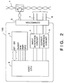
- Fig. 2 is a block diagram illustrating the construction of a control unit.
- the control unit indicated at numeral 100, is connected to the multiplex transmission lines 1 via wires 6, 7 and a connector 2, described later.
- a multiplex interface module 3 performs carrier detection and collision detection on the multiplex transmission lines 1 via the connector 2, reads serial data from the multiplex transmission lines 1, converts the serial data into parallel data (D 7 - D 0 ) and sends the parallel data to a host CPU 8.
- the multiplex interface module 3 converts parallel data from the host CPU 8 into serial data, performs a vertical parity check and computes an error detection code. In other words, the multiplex interface module 3 administers control of the physical layer level in the network.
- the host CPU 8 and the actual load are connected via the wires 6, 7, an input interface circuit 4 and an output interface circuit 5.
- a signal from the load is analyzed by the host CPU 8, where the signal is converted into a predetermined data format.
- the converted data is sent to the multiplex transmission lines 1 via the multiplex interface module 3.
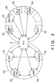
- Fig. 3 diagrammatically represents a multiplex communication map in the multiplex transmission system of the embodiment.
- the control system (a cooperative control multiplex system) of the multiplex transmission system shown in Fig. 3 is composed of a cooperative-control system multiplex network 20 and a body-system multiplex network 30. These two networks 20, 30 transmit and receive signals via an NIC (network integration controller) 21 operating as a relay unit.
- NIC network integration controller
- the EGI 22 is a control unit which administers control of the engine, such as control of fuel injection.
- control of the engine such as control of fuel injection.
- the EGI 22 sends back a torque-down execution signal and transmits a gear-position signal, etc. These control operations contribute to smooth starting and acceleration of the vehicle.
- the ABS/TRC 23 transmits a signal indicative of poor road conditions, a signal indicative of road surface ⁇ , etc., to the 4WS 24, and performs rear-wheel steering control suited to the travelling conditions.
- the ABS/TRC 23 performs an exchange of a system-down signal and a transmission-failure signal among the cooperative control units and carries out mutual monitoring of the systems.
- the MACS 25 is a control unit for an active suspension.
- Control units METER 31, A/CSW 35, A/CAMP 34, etc. which constitute the body-system multiplex network 30, transmit signals to and receive signals from solely the NIC 21 independently of the other control units.
- EXT 33 is a control unit which participates in fault diagnosis and inspection, the latter of which is performed on the manufacturing line.
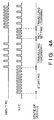
- Fig. 4A is a timing chart illustrating the relationship between the state of a vehicle and data transmitted from the control units NIC 21 and ABS/TRC 23.
- the NIC 21 transmits data at a shorter period in comparison with that which prevails when the vehicle is travelling.
- the ABS/TRC 23 has detected that the vehicle is turning, the signal transmission interval is shortened in comparison with the interval which prevails during ordinary vehicle travel. Examples of signals from the ABS/TRC 23 when the vehicle is turning are road-condition signals relating to a road having a low ⁇ , a road in a bad condition, etc. These signals are sent to the 4WS 24.
- Figs. 4B and 4C illustrate the details of the data transmission performed by the NIC 21 at starting of the engine and at resetting of the EGI 22, mentioned above.
- a starter switch (not shown) is turned from off to on in Fig. 4B (point a)
- starting of the engine begins and the NIC 21 begins to transmit a control signal to, say, the EGI 22, via the multiplex transmission lines 1.
- the period of time from point a to a point b at which the starter switch is turned from on to off is adopted as a starting-time control period.
- the EGI 22 is in an unstable state in which the engine is difficult to control. In particular, the conditions are such that control of engine torque is difficult. Consequently, the NIC 21 performs the transmission of data with regard to the EGI 22 in a period t 1 .
- the NIC 21 performs a transmission of data in a period t 2 as control for when the vehicle is travelling in an ordinary manner. It goes without saying that the periods t 1 and t 2 are related as follows: t 1 ⁇ t 2 .
- Fig. 4C is a timing chart illustrating data transmission control of the NIC 21 from resetting of the control unit EGI 22 until this control unit is restored to the normal state.
- the NIC 21 starts a timer (not shown) and begins transmission of data at period t 1 .
- the data transmission continues at the period t 1 for a fixed time T up to the moment timekeeping by the timer ends following the starting of the timer.
- the data transmission is performed at period t 2 as control for when the vehicle is travelling in an ordinary manner.
- the relation between the periods t 1 and t 2 is t 1 ⁇ t 2 .
- control stability at starting and resetting is assured.
- the other control units are capable of gaining the right to access the multiplex transmission lines.
- the transmission period of the signals representing the road conditions can be shortened, thereby making it possible to improve the reliability of data transmission when the vehicle is in a state in which it is sensitive to the road surface.
- a second embodiment of the present invention will now be described.
- the construction of the multiplex transmission system according to the following embodiment is the same as that of the multiplex transmission system in the first embodiment.
- the construction of the control units and the multiplex communication map in the multiplex transmission system are the same as those in the first embodiment. Accordingly, these need not be described again.
- Fig. 5 is a timing chart illustrating data transmission and reception among the control units EGI 22, NIC 21, ABS/TRC 23 and 4WS 24 connected to the multiplex transmission lines 1 in this embodiment. As shown in Fig. 5, the EGI 22 and NIC 21 perform data transmission periodically. These control units are set to have the highest orders of priority for data transmission/reception in the multiplex transmission lines 1.
- the ABS/TRC 23 and 4WS 24 have a lower order of priority than the EGI 22 and NIC 21.
- the order of priority for data transmission/reception of the control units in the multiplex transmission lines 1 is rewritten so that the transmission/reception of data between the ABS/TRC 23 and 4WS 24 assumes the highest priority. Then, in interval T, both of these control units periodically perform transmission/reception of data related to control of 4WS, etc.
- the data transmission/reception of the ABS/TRC and 4WS is given the highest order of priority in the interval T.
- the data transmission from the NIC is given the highest priority only when the engine is started or when system resetting is performed.
- the present invention is not limited to the foregoing embodiments.
- an arrangement may be adopted in which a party to a periodic transmission of data between two control units is changed over depending upon the controlled state of the vehicle.
- the ABS/TRC changes over the party to a periodic data transmission from EGI to 4WS when, with ABS/TRC adopting EGI as a specific control unit, data transmission/reception is being performed between the two control units (interval A in Fig. 6) and when there is an increase in the amount of communication with 4WS, which is a party that performs cooperative control having the highest order of priority as far as ABS/TRC is concerned (interval B in Fig. 6).
- Fig. 7 is a timing chart illustrating the relationship among data transmission timings of control units.
- a control unit C/UA EGI 22
- NIC 21 control unit C/UB
- the EGI 22 makes the period t 2 of the data transmission/reception with the ABS/TRC 23, which takes part in transmission/reception of control information having a high degree of importance in terms of vehicle safety, shorter than the period t 1 of the data transmission/reception with the NIC 21 whose degree of importance for control is not so high by comparison.
- the EGI 22 changes the degree of cooperative control depending upon the control unit which is the other party in the communication.
- a control unit C/UD (4WS 24) is capable of transmitting desired data by occupying the transmission lines upon taking into account the timing of the aforesaid data transmission/reception.
- the data transmission period which prevails when a data transmission/reception is performed periodically is changed over depending upon the control unit which is the other party, and the period of the data transmission/reception between control units taking part in important control is made shorter than the period of the data transmission/reception having a low degree of importance.
- it is possible to eliminate delays in terms of control such as a delay in the idling raising operation of the EGI and a delay in the steering operation of the 4WS, which is caused by a delay in judging the road surface.
- the multiplex transmission system is such that the control unit C/UA (EGI 22) possesses a map, which is illustrated in Fig. 8A, within a memory (not shown), with the period of data transmission/reception being changed based upon the relationship between the state of the vehicle and the control unit which is a party to communication. More specifically, based upon transmitted data from another control unit, the EGI 22 recognizes this control unit which is a party to the communication as well as the state of the vehicle and, based upon the results, decides the period of data transmission/reception from the map shown in Fig. 8A. The numerals in the map correspond to the period of the data transmission/reception.
- the EGI 22 receives transmitted data from, say, the ABS/TRC 23 and recognizes from this data that the vehicle is in a state in which it is travelling on a road having a low ⁇
- the EGI 22 selects "1" of vehicle state 3 from the map of Fig. 8(a), where "1" serves as the period of data transmission/reception with the ABS/TRC 23.
- the period of the data transmission/reception becomes 12 ms.
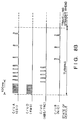
- Fig. 8B is a timing chart showing the relationship between the travelling state of a vehicle and a data transmission/reception among control units.
- the EGI 22 receives data and recognizes that the control unit which is a party to the communication is the 4WS 24 and that the vehicle is turning, the EGI 22 selects "1", namely 12 ms, as the data transmission/reception period from vehicle state 2 of the map shown in Fig. 8A. As a result, the EGI 22 performs a data transmission/reception with the 4WS at the period 12 ms.
- the EGI 22 selects "2", namely 24 ms, as the data transmission/reception period from vehicle state 2 of the map shown in Fig. 8A. As a result, the EGI 22 performs a data transmission/reception at this period.
- the EGI 22 When the above-mentioned data transmission/reception is ended and the EGI 22 receives transmitted data from the NIC 21 while the vehicle is still turning (vehicle state 2), the EGI 22 selects "7" from the map of Fig. 8A and performs a data transmission/reception at a period of 70 ms. It should be noted that the period of data transmission/reception is decided by a similar method even after the vehicle starts travelling straight ahead upon completing the turn. However, the details are not described here.
- a fifth embodiment of the present invention will now be described. It should be noted that the construction of the multiplex transmission system and multiplex communication map according to this embodiment are the same as those of the first embodiment and need not be described again.
- Fig. 9 is a block diagram illustrating the construction of a control unit according to this embodiment.
- the control unit indicated at numeral 100
- the control unit is connected to a wire harness, which includes the multiplex transmission lines 1, and a power-supply line 15 via the connector 2.
- the multiplex interface module 3 performs carrier detection and collision detection on the multiplex transmission lines 1 through BUSA, BUSB, reads serial data from the multiplex transmission lines 1, converts the serial data into parallel data (D 7 - D 0 ) and sends the parallel data to the host CPU 8.
- the multiplex interface module 3 converts parallel data from the host CPU 8 into serial data, performs a vertical parity check and computes an error detection code. In other words, the multiplex interface module 3 administers control of the physical layer level in the network.
- the host CPU 8 and the actual load are connected via the wires 6, 7, an input interface circuit 4 and an output interface circuit 5.
- a signal from the load is analyzed by the host CPU 8, where the signal is converted into a predetermined data format.
- the converted data is sent to the multiplex transmission lines 1 via the multiplex interface module 3.
- a battery (not shown) supplies a battery voltage of 12V to a D/D converter 10, which converts this voltage into an operating voltage V CC of the multiplex interface module 3 and host CPU 8.
- the voltage V cc is monitored at all times by a voltage monitoring unit 16. When the voltage value does not satisfy a predetermined value, the monitoring unit 16 regards this as an operating voltage error and so informs the host CPU 8.
- control at the time the engine is started in the cooperative-control multiplex system especially control for assuring good startability of the EGI.
- Fig. 10A is a timing chart showing the relationship between a change in the output voltage (the operating power-supply voltage of the multiplex interface module 3 or host CPU 8) of the D/D converter 10 in control unit 100, which change accompanies operation of a starter switch (not shown), and the operation of the control unit.
- the starter switch is turned from off to on in Fig. 10B (point a)
- the output voltage (power-supply voltage V CC ) of the D/D converter 10 gradually declines owing to consumption of power due to starting of the engine.
- the power-supply voltage of each control unit is monitored at all times by the voltage monitoring unit 16.
- the EGI 22 which contributes to engine control and the control unit (C/UA in this example) which transmits the data necessary for the EGI 22 receive signals from their internal voltage monitoring units 16 and thus learn of the fact that the voltage has dropped below the predetermined value.
- the EGI 22 receives a signal necessary for this control from the C/UA, which is the other control unit.
- the period of time from point a to a point b at which the power-supply voltage of this control unit returns to the predetermined value is adopted as the starting-time control period of the EGI 22.
- the EGI 22 is in an unstable state in which the engine is difficult to control. In particular, the conditions are such that control of engine torque is difficult. Consequently, the C/UA periodically transmits data to the EGI 22 and makes this period (t 1 ) shorter than the ordinary period (t 2 ), described below.
- Fig. 11A is a timing chart illustrating data transmission control from resetting of the control unit until this control unit is restored to the normal state.
- the NIC 21 is a control unit, which serves as a relay unit in the cooperative-control multiplex system, administers the transmission of signals that are important in terms of control. Accordingly, in a case where the NIC 21 undergoes system reset as caused by an abnormality in the power-supply system during vehicle travel, urgent restoration of control becomes necessary.
- the NIC 21 undergoes system reset at point d in Fig. 11A, the NIC 21 starts a timer (not shown) and forcibly transmits data to the other control unit at the constant period t.
- the data transmission continues at the period t for a fixed time T up to the moment timekeeping by the timer ends following the starting of the timer. Then, at elapse of the time T, the ordinary communication mode is restored.
- the data transmission from the control unit C/UA to the EGI 22 is returned from a periodic data transmission to ordinary communication when the power-supply voltage of the control unit C/UA returns to the predetermined value.
- the control unit C/UA recognizes, on its own or based upon information from the other control unit, that the starter switch has been turned from on to off [point c in Fig. 10B], whereupon the ordinary communication mode is restored.
- the timer is started, a data transmission is forcibly performed at a fixed period with respect to the other control unit, and the ordinary communication mode is restored at the end of the timekeeping operation performed by the timer.
- the NIC 21 performs data transmission at the fixed period after the occurrence of the system reset and a predetermined signal is received [at point e in Fig. 11B] from the other control unit (C/UB in this example)
- the ordinary communication mode may be restored.
- an engine-stability signal which indicates that the rotational speed of the engine has attained a stipulated value, or a busy signal from the travel control system, is used as the predetermined signal.
Description
- This invention relates to a multiplex transmission system and, more particularly, to a multiplex transmission system for connecting a plurality of control units in a vehicle to a multiplex transmission line and performing an exchange of information among the control units.
- In the US-4,825,362, a data network system for a vehicle having a plurality of separate and distinct control computers carrying out a predetermined control function of the vehicle and a data communication line for communicating data among control computers is described. One of the control computers determines the number of the other computers which are linked with the data communication line, and in response to that number, a data transfer rate output from each of the control computers to the data communication line is determined. By this system communicating of data among a multiplicity of computers is less susceptible to disruption by noise inherent in a motor vehicle environment. This data network system for a vehicle maintains good communication even when the data on the communication line of the network is being transferred at a high data rate. The system described in this document comprises data communication means for communicating data among distinct control computers, a master computer, determination means provided in said master computer for determining the number of computers which are linked with said data communication means and setting means for setting a data transfer speed between each control computer and said data communication means.
- In a multiplex transmission system which employs decentralized multiplexing for transmitting and receiving signals between electrical accessories mounted in a vehicle, plural items of data are multiplexed on a time-shared basis on a pair of transmission lines, and serial transmission is the fundamental type of transmission used.
- In a multiplex transmission system employing such decentralized multiplex transmission, each node has its own transmission LSI, microprocessor or the like, and these perform such operations as transmission control and analysis of received information in accordance with presecribed algorithms.
- However, since each node transmits data, which is necessary for control, at fixed intervals in the prior art described above, a problem which arises is that it is difficult for another node which performs another kind of control to interrupt the data transmission, and therefore a delay develops in this control. In addition, in a case where the period of a data transmission is lengthened, the period for updating the data also is lengthened as a result, and this makes it easy for transmission errors and control delay to occur.
- In a case where a data transmission is performed periodically between nodes upon deciding order of priority, a problem which arises is that, depending upon the travelling state of the vehicle, the frequency of data transmission with nodes having a low order of priority rises, as a result of which a data transmission with these nodes either cannot be carried out or is delayed.
- Furthermore, since each node transmits data necessary for control at fixed intervals (i.e., at a fixed period), as mentioned above, the density of data on a transmission line is constant at all times regardless of whether the data is important or not in terms of control. In particular, if the amount of data having comparatively little importance transmitted on a transmission line occupies a major share of the line, the probability of performing a transmission of data having a high degree of importance declines, and this causes a delay in control relating to this data.
- Another problem is that after the ignition of a vehicle is turned on (IG-ON), the voltage supplied to each control unit declines owing to consumption of power by the starter during starting of the engine, and the transmission operation is destabilized as a result. Though this destabilizing influence upon the transmission operation becomes particularly pronounced at cold starting of the engine, the following problems also arise if the unit which administers engine control receives this destabilizing influence even when the engine is not being cold-started:
- (1) Control at starting cannot be performed normally. This may make it difficult or impossible to start the engine or may cause a delay in starting.
- (2) Checking of transmitted and received data (control of an ACK signal, which is a reception acknowledgement signal) at the control unit cannot be performed normally.
- In a case where a specific control unit undergoes system reset owing to an abnormality in the power-supply system during travelling of the vehicle, the state of the engine or control unit will be unstable even if the power-supply system is restored to normal. Consequently, reception of a signal from another control unit cannot be performed reliably, and engine control cannot be restored or develops a delay.
- An object of the present invention is to provide a multiplex transmission system which raises the efficiency of data transmission among control units constructing the multiplex transmission system, and which prevents control delay and transmission error.
- Another another object of the present invention is to provide a multiplex transmission system in which signal density on a transmission line of the multiplex transmission system is made appropriate to perform transmission efficiently and prevent control delay.
- Still another object of the present invention is to provide a multiplex transmission system for hastening rise time when operation of a control unit constructing the multiplex transmission system is restored from the unstable to the stable state.
- According to the present invention, the foregoing objects are attained by providing a multiplex transmission system in which a plurality of control units connected in decentralized fashion to a common transmission line transmit and receive information to and from one another, comprising informing means for informing each control unit of the travelling state of a vehicle in the form of information, and transmission control means for changing a method in which information is transmitted among the plurality of control units, the change being made in dependence upon the travelling state of the vehicle.
- In a preferred embodiment, the transmission control means is adapted to transmit information among the control units at a prescribed period under ordinary conditions, and to change the method of transmission at starting of an engine in such a manner that the information is transmitted at a period shorter than the prescribed period.
- In a preferred embodiment, the transmission control means decides an order of priority for transmission of information among the plurality of control units, and changes the order of priority in dependence upon the travelling state of the vehicle.
- In a preferred embodiment, the transmission control means changes over transmission of information among the plurality of control units from periodic transmission to transmission in accordance with occurrence of an event, or from transmission in accordance with occurrence of an event to periodic transmission, in dependence upon the travelling state of the vehicle.
- In a preferred embodiment, the transmission control means performs transmission of information with respect to a specific control unit periodically, renders transmission of information with respect to another control unit transmission that is in accordance with occurrence of an event, and changes the specific control unit in dependence upon the traveling state of the vehicle.
- In another aspect of the present invention, the foregoing objects are attained by providing a multiplex transmission system in which a plurality of control units connected in decentralized fashion to a common transmission line transmit and receive information to and from one another, comprising means for specifying a communicating-party control unit with which the plurality of control units perform transmission and reception of information, and transmission control means for performing transmission of information with respect to the specified communicating-party control unit periodically, and changing the period of this transmission in dependence upon the specified communicating-party control unit.
- According to a preferred embodiment, the transmission control means includes means for sensing a travelling state of a vehicle, wherein the transmission period is changed in dependence upon the communicating-party control unit and the travelling state of the vehicle.
- In another aspect of the present invention, the foregoing objects are attained by providing a multiplex transmission system in which a plurality of control units connected in decentralized fashion to a common transmission line transmit and receive information to and from one another, comprising first control means for performing control in such a manner that information necessary for controlling one of the plurality of control units is transmitted from another control unit, discriminating means for determining whether operation of each control unit is in a stable state or unstable state; and second control means for changing the method of transmission control, which is performed by the first control means, between one method when a control unit is in the stable state and another method when the control unit is in the unstable state, based upon results of determination made by the discriminating means.
- In a preferred embodiment, the second control means is so adapted that when the discriminating means has determined that one of the control units has performed a system reset and is in the unstable state, the second control means changes the method of transmission control, which is performed by the first control means, for a predetermined time following the system reset in such a manner that another control unit which transmits information necessary for control of the one control unit performs transmission of information at a period shorter than that which prevails when the one control unit is in the stable state.
- In a preferred embodiment, the second control means is so adapted that when the discriminating means has determined that a certain control unit is in the stable state, the second control means changes the method of transmission control, which is performed by the first control means, in such a manner that another control unit which transmits information necessary for control of the certain control unit performs transmission of information in accordance with occurrence of an event, and when the discriminating means has determined that the certain control unit is in the unstable state, the second control means changes the method of transmission control, which is performed by the first control means, in such a manner that the other control unit performs transmission of information periodically.
- Other features and advantages of the present invention will be apparent from the following description taken in conjunction with the accompanying drawings, in which like reference characters designate the same or similar parts throughout the figures thereof.
-
- Fig. 1 is a diagram showing the construction of a multiplex transmission system according to an embodiment of the present invention;
- Fig. 2 is a block diagram illustrating the construction of a control unit;
- Fig. 3 is a diagram illustrating a multiplex communication map according to the embodiment;
- Fig. 4A is a timing chart illustrating the relationship between the state of a vehicle and data transmitted from control units in a multiplex transmission system according to a first embodiment;
- Fig. 4B is a timing chart illustrating communication control at starting of an engine in the multiplex transmission system according to the first embodiment;
- Fig. 4C is a timing chart illustrating control at resetting of a control unit in a multiplex transmission system according to the first embodiment;
- Fig. 5 is a timing chart illustrating data transmission and reception among control units in a second embodiment;
- Fig. 6 is a timing chart illustrating a modification of the control state of a vehicle and transmission of data among control units;
- Fig. 7 is a timing chart illustrating the relationship among data transmission timings of control units in a multiplex transmission system according to a third embodiment;
- Fig. 8A is a diagram showing a map of data transmission/reception periods in a multiplex transmission system according to a fourth embodiment;
- Fig. 8B is a timing chart illustrating the state of a vehicle and data transmission/reception among communicating-party control units;
- Fig. 9 is a block diagram illustrating the construction of a control unit in a multiplex transmission system according to a fifth embodiment;
- Fig. 10A is a timing chart illustrating communication control at starting of an engine according to a fifth embodiment;
- Fig. 10B is a timing chart illustrating a modification of communication control at starting of an engine according to the fifth embodiment;
- Fig. 11A is a timing chart illustrating control corresponding to resetting of a communication system during vehicle travel in the fifth embodiment; and
- Fig. 11B is a timing chart illustrating a modification of control corresponding to resetting of a communication system during vehicle travel in the fifth embodiment,
- Preferred embodiments of the present invention will now be described in detail with reference to the accompanying drawings.
- A first embodiment of the present invention will now be described.
- Fig. 1 illustrates a multiplex transmission system according to a first embodiment of the invention. As shown, six control units A through F are connected to a pair of
multiplex transmission lines 1. The control units transmit and receive data to and from one another by CSMA/CD via themultiplex transmission lines 1. - Fig. 2 is a block diagram illustrating the construction of a control unit. As shown in Fig. 2, the control unit, indicated at
numeral 100, is connected to themultiplex transmission lines 1 viawires connector 2, described later. Amultiplex interface module 3 performs carrier detection and collision detection on themultiplex transmission lines 1 via theconnector 2, reads serial data from themultiplex transmission lines 1, converts the serial data into parallel data (D7 - D0) and sends the parallel data to ahost CPU 8. In addition, themultiplex interface module 3 converts parallel data from thehost CPU 8 into serial data, performs a vertical parity check and computes an error detection code. In other words, themultiplex interface module 3 administers control of the physical layer level in the network. - The
host CPU 8 and the actual load (not shown) are connected via thewires input interface circuit 4 and anoutput interface circuit 5. A signal from the load is analyzed by thehost CPU 8, where the signal is converted into a predetermined data format. The converted data is sent to themultiplex transmission lines 1 via themultiplex interface module 3. - Fig. 3 diagrammatically represents a multiplex communication map in the multiplex transmission system of the embodiment.
- The control system (a cooperative control multiplex system) of the multiplex transmission system shown in Fig. 3 is composed of a cooperative-control
system multiplex network 20 and a body-system multiplex network 30. These twonetworks - The transmission/reception of signals among cooperative
control units EGI 22, ABS/TRC 23,4WS 24 andMACS 25, which constitute the cooperative- controlsystem multiplex network 20, and between each of these control units and theNIC 21, is performed in the directions indicated by the arrows. Signals which the cooperative control units transmit to and receive from one another are referred to as "cooperative signals", and signals which theNIC 21 and cooperative control units transmit to and receive from each other are referred to as "body signals". - The principal functions of the cooperative control units will now be described in brief.
- The
EGI 22 is a control unit which administers control of the engine, such as control of fuel injection. In response to reception of a torque-down request from the ABS/TRC 23, which is related to control of antiskid braking, theEGI 22 sends back a torque-down execution signal and transmits a gear-position signal, etc. These control operations contribute to smooth starting and acceleration of the vehicle. - In order to improve the stability of the vehicle, the ABS/
TRC 23 transmits a signal indicative of poor road conditions, a signal indicative of road surface µ, etc., to the4WS 24, and performs rear-wheel steering control suited to the travelling conditions. In addition, for the purpose of improving stability, the ABS/TRC 23 performs an exchange of a system-down signal and a transmission-failure signal among the cooperative control units and carries out mutual monitoring of the systems. TheMACS 25 is a control unit for an active suspension. -
Control units METER 31, A/CSW 35, A/CAMP 34, etc., which constitute the body-system multiplex network 30, transmit signals to and receive signals from solely theNIC 21 independently of the other control units.EXT 33 is a control unit which participates in fault diagnosis and inspection, the latter of which is performed on the manufacturing line. - Data transmission control in the cooperative-control multiplex system of this embodiment will be described next.
- Fig. 4A is a timing chart illustrating the relationship between the state of a vehicle and data transmitted from the
control units NIC 21 and ABS/TRC 23. When the state of the vehicle is such that the engine is being started or theEGI 22 is being reset, as shown in Fig. 4A, theNIC 21 transmits data at a shorter period in comparison with that which prevails when the vehicle is travelling. When the ABS/TRC 23 has detected that the vehicle is turning, the signal transmission interval is shortened in comparison with the interval which prevails during ordinary vehicle travel. Examples of signals from the ABS/TRC 23 when the vehicle is turning are road-condition signals relating to a road having a low µ, a road in a bad condition, etc. These signals are sent to the4WS 24. - Figs. 4B and 4C illustrate the details of the data transmission performed by the
NIC 21 at starting of the engine and at resetting of theEGI 22, mentioned above. - When a starter switch (not shown) is turned from off to on in Fig. 4B (point ⓐ), starting of the engine begins and the
NIC 21 begins to transmit a control signal to, say, theEGI 22, via themultiplex transmission lines 1. The period of time from point ⓐ to a point ⓑ at which the starter switch is turned from on to off is adopted as a starting-time control period. During this period, theEGI 22 is in an unstable state in which the engine is difficult to control. In particular, the conditions are such that control of engine torque is difficult. Consequently, theNIC 21 performs the transmission of data with regard to theEGI 22 in a period t1. Then, upon elapse of the starting-time control period, theNIC 21 performs a transmission of data in a period t2 as control for when the vehicle is travelling in an ordinary manner. It goes without saying that the periods t1 and t2 are related as follows: t1 < t2. - Fig. 4C is a timing chart illustrating data transmission control of the
NIC 21 from resetting of thecontrol unit EGI 22 until this control unit is restored to the normal state. - In a case where
EGI 22 is reset at point ⓒ in Fig. 4C, theNIC 21 starts a timer (not shown) and begins transmission of data at period t1. The data transmission continues at the period t1 for a fixed time T up to the moment timekeeping by the timer ends following the starting of the timer. Then, at elapse of the time T, the data transmission is performed at period t2 as control for when the vehicle is travelling in an ordinary manner. Here also the relation between the periods t1 and t2 is t1 < t2. - Thus, by changing the period of data transmission from a specific control unit in dependence upon the state of the vehicle, control stability at starting and resetting is assured. In addition, when the vehicle is in a state other than that which prevails at the time of starting or resetting, the other control units are capable of gaining the right to access the multiplex transmission lines.
- Further, when the vehicle is turning, the transmission period of the signals representing the road conditions can be shortened, thereby making it possible to improve the reliability of data transmission when the vehicle is in a state in which it is sensitive to the road surface.
- A second embodiment of the present invention will now be described. The construction of the multiplex transmission system according to the following embodiment is the same as that of the multiplex transmission system in the first embodiment. In addition, the construction of the control units and the multiplex communication map in the multiplex transmission system are the same as those in the first embodiment. Accordingly, these need not be described again.
- Fig. 5 is a timing chart illustrating data transmission and reception among the
control units EGI 22,NIC 21, ABS/TRC 23 and4WS 24 connected to themultiplex transmission lines 1 in this embodiment. As shown in Fig. 5, theEGI 22 andNIC 21 perform data transmission periodically. These control units are set to have the highest orders of priority for data transmission/reception in themultiplex transmission lines 1. - In ordinary data transmission/reception, the ABS/
TRC 23 and4WS 24 have a lower order of priority than theEGI 22 andNIC 21. However, when the vehicle is turning and travelling on a road having a low µ in interval T, the order of priority for data transmission/reception of the control units in themultiplex transmission lines 1 is rewritten so that the transmission/reception of data between the ABS/TRC 23 and4WS 24 assumes the highest priority. Then, in interval T, both of these control units periodically perform transmission/reception of data related to control of 4WS, etc. - After the transmission/reception of data between the ABS/
TRC 23 and4WS 24 in interval T, the transmission/reception of data between theEGI 22 andNIC 21 again assumes the highest priority in themultiplex transmission lines 1. - Thus, when a control unit having a high order of priority on the transmission lines is performing a transmission/reception of data and, at such time, there is an increase in the frequency of a data transmission of a control unit important in terms of traveling safety of the vehicle even though this control unit has a lower order of priority, the order of priority of this control unit is raised temporarily, thereby making it possible to improve vehicle safety.
- In this embodiment, the data transmission/reception of the ABS/TRC and 4WS is given the highest order of priority in the interval T. However, it may be so arranged that the data transmission from the NIC is given the highest priority only when the engine is started or when system resetting is performed.
- The present invention is not limited to the foregoing embodiments. For example, as shown in Fig. 6, an arrangement may be adopted in which a party to a periodic transmission of data between two control units is changed over depending upon the controlled state of the vehicle. More specifically, the ABS/TRC changes over the party to a periodic data transmission from EGI to 4WS when, with ABS/TRC adopting EGI as a specific control unit, data transmission/reception is being performed between the two control units (interval A in Fig. 6) and when there is an increase in the amount of communication with 4WS, which is a party that performs cooperative control having the highest order of priority as far as ABS/TRC is concerned (interval B in Fig. 6).
- By adopting this expedient, a data transmission between ABS/TRC and the control unit that performs cooperative control having the highest order of priority can be executed without interfering with a data transmission with regard to other control units.
- Control of data transmission in a cooperative control multiplex system according to a third embodiment will now be described.
- Fig. 7 is a timing chart illustrating the relationship among data transmission timings of control units. As shown in Fig. 7, when a control unit C/UA (EGI 22) receives an initial transmission of data (
data ① in Fig. 7) from a control unit C/UB (NIC 21), it becomes aware of the fact that the party to control is theNIC 21. From reception ofdata ① onward, both control units transmit and receive data at a period t1 (t1 = 100 ms). - On the other hand, when the
EGI 22 receives a transmission of data (data ② in Fig. 7) from a control unit C/UC (ABS/TRC 23) after transmission/reception of data with respect to theNIC 21, it recognizes the fact that the other party is the ABS/TRC 23, just as in the case of theNIC 21. From reception ofdata ② onward, theEGI 22 and ABS/TRC 23 transmit and receive data at a period t2 (t2 = 12 ms). That is, theEGI 22 makes the period t2 of the data transmission/reception with the ABS/TRC 23, which takes part in transmission/reception of control information having a high degree of importance in terms of vehicle safety, shorter than the period t1 of the data transmission/reception with theNIC 21 whose degree of importance for control is not so high by comparison. In other words, theEGI 22 changes the degree of cooperative control depending upon the control unit which is the other party in the communication. - Another reason for making the period of data transmission/reception between the
EGI 22 and the ABS/TRC 23 shorter than that between theEGI 22 and theNIC 21 is to lower the data transmission density on the data transmission lines between theEGI 22 andNIC 21. Consequently, while theEGI 22 andNIC 21 are performing a data transmission/reception at a fixed period, a control unit C/UD (4WS 24) is capable of transmitting desired data by occupying the transmission lines upon taking into account the timing of the aforesaid data transmission/reception. - Thus, the data transmission period which prevails when a data transmission/reception is performed periodically is changed over depending upon the control unit which is the other party, and the period of the data transmission/reception between control units taking part in important control is made shorter than the period of the data transmission/reception having a low degree of importance. As a result, it is possible to eliminate delays in terms of control, such as a delay in the idling raising operation of the EGI and a delay in the steering operation of the 4WS, which is caused by a delay in judging the road surface.
- Further, by reducing the density of control data, which has a low degree of importance, on the transmission lines, it is possible to raise the data transmission probability of other control units.
- A fourth embodiment according to the present invention will now be described.
- The multiplex transmission system according to this embodiment is such that the control unit C/UA (EGI 22) possesses a map, which is illustrated in Fig. 8A, within a memory (not shown), with the period of data transmission/reception being changed based upon the relationship between the state of the vehicle and the control unit which is a party to communication. More specifically, based upon transmitted data from another control unit, the
EGI 22 recognizes this control unit which is a party to the communication as well as the state of the vehicle and, based upon the results, decides the period of data transmission/reception from the map shown in Fig. 8A. The numerals in the map correspond to the period of the data transmission/reception. - In a case where the
EGI 22 receives transmitted data from, say, the ABS/TRC 23 and recognizes from this data that the vehicle is in a state in which it is travelling on a road having a low µ, theEGI 22 selects "1" ofvehicle state ③ from the map of Fig. 8(a), where "1" serves as the period of data transmission/reception with the ABS/TRC 23. As a result, the period of the data transmission/reception becomes 12 ms. - Fig. 8B is a timing chart showing the relationship between the travelling state of a vehicle and a data transmission/reception among control units. In Fig. 8B, in a case where the
EGI 22 receives data and recognizes that the control unit which is a party to the communication is the4WS 24 and that the vehicle is turning, theEGI 22 selects "1", namely 12 ms, as the data transmission/reception period fromvehicle state ② of the map shown in Fig. 8A. As a result, theEGI 22 performs a data transmission/reception with the 4WS at the period 12 ms. In a case where data is subsequently received from the ABS/TRC 23 and the vehicle is still in the process of turning, theEGI 22 selects "2", namely 24 ms, as the data transmission/reception period fromvehicle state ② of the map shown in Fig. 8A. As a result, theEGI 22 performs a data transmission/reception at this period. - When the above-mentioned data transmission/reception is ended and the
EGI 22 receives transmitted data from theNIC 21 while the vehicle is still turning (vehicle state ②), theEGI 22 selects "7" from the map of Fig. 8A and performs a data transmission/reception at a period of 70 ms. It should be noted that the period of data transmission/reception is decided by a similar method even after the vehicle starts travelling straight ahead upon completing the turn. However, the details are not described here. - Thus, by deciding beforehand the period of data transmission/reception between control units based upon the relationship between the travelling state of the vehicle and the control units which are the parties to communication, it is possible to transmit and receive, without delay, data which has a close relationship to vehicle travelling state, such as the turning state, and which takes part in rear-wheel steering and traction having a high degree of importance in terms of control.
- A fifth embodiment of the present invention will now be described. It should be noted that the construction of the multiplex transmission system and multiplex communication map according to this embodiment are the same as those of the first embodiment and need not be described again.
- Fig. 9 is a block diagram illustrating the construction of a control unit according to this embodiment. As shown in Fig. 9, the control unit, indicated at
numeral 100, is connected to a wire harness, which includes themultiplex transmission lines 1, and a power-supply line 15 via theconnector 2. Themultiplex interface module 3 performs carrier detection and collision detection on themultiplex transmission lines 1 through BUSA, BUSB, reads serial data from themultiplex transmission lines 1, converts the serial data into parallel data (D7 - D0) and sends the parallel data to thehost CPU 8. In addition, themultiplex interface module 3 converts parallel data from thehost CPU 8 into serial data, performs a vertical parity check and computes an error detection code. In other words, themultiplex interface module 3 administers control of the physical layer level in the network. - The
host CPU 8 and the actual load (not shown) are connected via thewires input interface circuit 4 and anoutput interface circuit 5. A signal from the load is analyzed by thehost CPU 8, where the signal is converted into a predetermined data format. The converted data is sent to themultiplex transmission lines 1 via themultiplex interface module 3. - A battery (not shown) supplies a battery voltage of 12V to a D/
D converter 10, which converts this voltage into an operating voltage VCC of themultiplex interface module 3 andhost CPU 8. The voltage Vcc is monitored at all times by avoltage monitoring unit 16. When the voltage value does not satisfy a predetermined value, themonitoring unit 16 regards this as an operating voltage error and so informs thehost CPU 8. - Described next will be control at the time the engine is started in the cooperative-control multiplex system, especially control for assuring good startability of the EGI.
- Fig. 10A is a timing chart showing the relationship between a change in the output voltage (the operating power-supply voltage of the
multiplex interface module 3 or host CPU 8) of the D/D converter 10 incontrol unit 100, which change accompanies operation of a starter switch (not shown), and the operation of the control unit. When the starter switch is turned from off to on in Fig. 10B (point ⓐ), the output voltage (power-supply voltage VCC) of the D/D converter 10 gradually declines owing to consumption of power due to starting of the engine. As mentioned above, the power-supply voltage of each control unit is monitored at all times by thevoltage monitoring unit 16. TheEGI 22 which contributes to engine control and the control unit (C/UA in this example) which transmits the data necessary for theEGI 22 receive signals from their internalvoltage monitoring units 16 and thus learn of the fact that the voltage has dropped below the predetermined value. - At starting of the engine, the
EGI 22 receives a signal necessary for this control from the C/UA, which is the other control unit. The period of time from point ⓐ to a point ⓑ at which the power-supply voltage of this control unit returns to the predetermined value is adopted as the starting-time control period of theEGI 22. During this period, theEGI 22 is in an unstable state in which the engine is difficult to control. In particular, the conditions are such that control of engine torque is difficult. Consequently, the C/UA periodically transmits data to theEGI 22 and makes this period (t1) shorter than the ordinary period (t2), described below. - When the power-supply voltage of the control unit C/UA returns to the predetermined value, data is transmitted from the C/UA to the
EGI 22 only when there is a change in the ordinary communication mode, namely when an event occurs and there is a change in the status of the data transmitted from the C/UA. As a result, theEGI 22 begins performing ordinary control. Accordingly, here the period t2 is not a fixed period. - Described next will be control for dealing with resetting of the communication system, during travel, in the cooperative-control multiplex system.
- Fig. 11A is a timing chart illustrating data transmission control from resetting of the control unit until this control unit is restored to the normal state.
- As mentioned earlier, the
NIC 21 is a control unit, which serves as a relay unit in the cooperative-control multiplex system, administers the transmission of signals that are important in terms of control. Accordingly, in a case where theNIC 21 undergoes system reset as caused by an abnormality in the power-supply system during vehicle travel, urgent restoration of control becomes necessary. - In a case where the
NIC 21 undergoes system reset at point ⓓ in Fig. 11A, theNIC 21 starts a timer (not shown) and forcibly transmits data to the other control unit at the constant period t. The data transmission continues at the period t for a fixed time T up to the moment timekeeping by the timer ends following the starting of the timer. Then, at elapse of the time T, the ordinary communication mode is restored. - Thus, as described above, even when there is a drop in the power-supply voltage of a control unit at starting of the engine, the transmission of data to the control unit which administers engine control is performed faster than usual and periodically during this period. As a result, the communication operation is prevented from becoming unstable.
- Further, even if a reset occurs in the control unit, which takes parts in the communication system, during vehicle travel, after the reset the data is transmitted forcibly at a constant period to the other control unit which receives the data from the first-mentioned control unit. Accordingly, rapid restoration of the control unit is possible.
- In control at starting of the engine in the fifth embodiment described above, the data transmission from the control unit C/UA to the
EGI 22 is returned from a periodic data transmission to ordinary communication when the power-supply voltage of the control unit C/UA returns to the predetermined value. However, as shown in Fig. 10B, an arrangement may be adopted in which the control unit C/UA recognizes, on its own or based upon information from the other control unit, that the starter switch has been turned from on to off [point ⓒ in Fig. 10B], whereupon the ordinary communication mode is restored. - In a case where the
NIC 21 undergoes system reset in control during vehicle travel, the timer is started, a data transmission is forcibly performed at a fixed period with respect to the other control unit, and the ordinary communication mode is restored at the end of the timekeeping operation performed by the timer. If, as shown in Fig. 11B, theNIC 21 performs data transmission at the fixed period after the occurrence of the system reset and a predetermined signal is received [at point ⓔ in Fig. 11B] from the other control unit (C/UB in this example), the ordinary communication mode may be restored. Here an engine-stability signal, which indicates that the rotational speed of the engine has attained a stipulated value, or a busy signal from the travel control system, is used as the predetermined signal. - As many apparently widely different embodiments of the present invention can be made without departing from the spirit and scope thereof, it is to be understood that the invention is not limited to the specific embodiments thereof except as defined in the appended claims.
Claims (12)
- A multiplex transmission system, for use in an automotive vehicle, in which a plurality of control units (100) connected in decentralized fashion to a common transmission line (1) transmit and receive information to and from one another, comprising:sensing means for sensing a travelling state of said automotive vehicle, andcommunication control means for changing the method of communication utilized among said plurality of control units (100) in dependence upon said travelling state.
- A multiplex transmission system, for use in an automotive vehicle, in which a plurality of control units (100) connected in decentralized fashion to a common transmission line (1) transmit and receive information to and from one another, comprising:discriminating means for determining whether operation of the control unit (100) is in a stable or unstable state, andcommunication control means for changing the method of communication utilized among said plurality of control units (100) based upon results of the determination made by said discriminating means.
- A multiplex transmission system, for use in an automotive vehicle, in which a plurality of control units (100) connected in decentralized fashion to a common transmission line (1) transmit and receive information to and from one another, comprising:recognizing means for recognizing the other party of the communication,communication control means for changing the method of communication utilized among the plurality of control units (100) depending upon the control unit (100) which is the other party in the communication recognized by said recognizing means.
- The system according to one of the preceding claims, characterized in that said communication control means is adapted to communicate information among said control units (100) at a prescribed period under ordinary conditions, and to change the method of communication at starting of an engine in such a manner that the information is transmitted at a period shorter than said prescribed period.
- The system according to claim 1, characterized in that said communication control means decides an order of priority for communication of information among said plurality of control units (100) and changes said order of priority in dependence upon said travelling state of said vehicle.
- The system according to claim 1 characterized in that said communication control means changes over the method of communication among the plurality of control units (100) from a periodic communication to a communication in accordance with the occurrence of an event, or from a communication in accordance with the occurrence of an event to a periodic communication, in dependence upon said travelling state of said vehicle.
- The system according to claim 6, characterized in that said communication control means which performs communication of information with respect to a specific control unit (100) periodically, renders communication of information with respect to another control unit (100) in accordance with the occurrence of an event, and changes said specific control unit (100) in dependence upon said travelling state of said vehicle.
- The system according to one of the preceding claims, characterized by means for specifying a communication control means with which said plurality of control units (100) perform transmission and reception of information, wherein said communication control means performs transmission of information with respect to said specified communication control means periodically, and changes the period of this transmission in dependence upon said specified communication control means.
- The system according to claim 8, characterized in that said period of transmission is changed in dependence upon said specified communication control means and said travelling state of said vehicle.
- The system according to claim 2, characterized by comprising:first communication control means for performing control in such a manner that information necessary for controlling one of said plurality of control units (100) is transmitted from another control unit (100),second communication control means for changing the method of communication, which is performed by the first communication control means, between one method when a control unit (100) is in the stable state and another method when the control unit (100) is in the unstable state, based upon results of determination made by said discriminating means.
- The system according to claim 10, characterized in that said second communication control means is so adapted that when said discriminating means has determined that one of the control units (100) has performed a system reset and is in the unstable state, said second communication control means changes the method of communication which is performed by said first communication control means, for a predetermined time following the system reset in such a manner that another control unit (100) which transmits information necessary for control of said one control unit (100) performs transmission of information at a period shorter than that which prevails when said one control unit (100) is in the stable state.
- The system according to claim 10, characterized in that said second communication control means is so adapted that when said discriminating means has determined that a certain control unit (100) is in the stable state, said second communication control means changes the method of transmission control, which is performed by said first communication control means, in such a manner that another control unit (100) which transmits information necessary for control of said certain control unit performs transmission of information in accordance with occurrence of an event, and when said discriminating means has determined that said certain control unit (100) is in the unstable state, said second control means changes the method of communication, which is performed by said first control means, in such a manner that said other control unit (100) performs transmission of information periodically.
Applications Claiming Priority (6)
| Application Number | Priority Date | Filing Date | Title |
|---|---|---|---|
| JP2241277A JP2904304B2 (en) | 1990-09-13 | 1990-09-13 | Multiplex transmission equipment |
| JP241277/90 | 1990-09-13 | ||
| JP248724/90 | 1990-09-20 | ||
| JP2248724A JP2904305B2 (en) | 1990-09-20 | 1990-09-20 | Multiplex transmission equipment |
| JP2248725A JP2904306B2 (en) | 1990-09-20 | 1990-09-20 | Multiplex transmission equipment |
| JP248725/90 | 1990-09-20 |
Publications (3)
| Publication Number | Publication Date |
|---|---|
| EP0475406A2 EP0475406A2 (en) | 1992-03-18 |
| EP0475406A3 EP0475406A3 (en) | 1994-08-24 |
| EP0475406B1 true EP0475406B1 (en) | 1997-04-23 |
Family
ID=27332924
Family Applications (1)
| Application Number | Title | Priority Date | Filing Date |
|---|---|---|---|
| EP91115470A Expired - Lifetime EP0475406B1 (en) | 1990-09-13 | 1991-09-12 | Multiplex transmission system for vehicles |
Country Status (4)
| Country | Link |
|---|---|
| US (1) | US5343470A (en) |
| EP (1) | EP0475406B1 (en) |
| KR (1) | KR960000605B1 (en) |
| DE (1) | DE69125772T2 (en) |
Families Citing this family (17)
| Publication number | Priority date | Publication date | Assignee | Title |
|---|---|---|---|---|
| DE59202560D1 (en) * | 1991-11-26 | 1995-07-20 | Siemens Ag | BUS SYSTEM. |
| DE4392671T1 (en) * | 1992-06-10 | 1995-06-01 | Ford Werke Ag | Communication system for motor vehicles |
| DE4219669B4 (en) * | 1992-06-16 | 2007-08-09 | Robert Bosch Gmbh | Control unit for calculating control variables for repetitive control operations |
| JP3453405B2 (en) * | 1993-07-19 | 2003-10-06 | マツダ株式会社 | Multiplex transmission equipment |
| FR2709580B1 (en) * | 1993-09-02 | 1995-10-13 | Cit Alcatel | Signaling protocol supporting multimedia services. |
| GB9605048D0 (en) * | 1996-03-09 | 1996-05-08 | Jaguar Cars | Multiplexed electronic control systems |
| JP2002026924A (en) * | 2000-07-06 | 2002-01-25 | Denso Corp | Data repeater and multiplex communication system |
| JP3578058B2 (en) * | 2000-07-13 | 2004-10-20 | 株式会社デンソー | Multiplex communication system |
| US7516244B2 (en) | 2003-07-02 | 2009-04-07 | Caterpillar Inc. | Systems and methods for providing server operations in a work machine |
| US7532640B2 (en) | 2003-07-02 | 2009-05-12 | Caterpillar Inc. | Systems and methods for performing protocol conversions in a machine |
| US7983820B2 (en) | 2003-07-02 | 2011-07-19 | Caterpillar Inc. | Systems and methods for providing proxy control functions in a work machine |
| DE102004021301A1 (en) * | 2004-04-29 | 2005-11-24 | Continental Aktiengesellschaft | Control device and method for controlling data bus devices |
| DE102006047141A1 (en) * | 2006-10-05 | 2008-04-10 | Robert Bosch Gmbh | Method and device for determining a target state |
| US7719411B2 (en) * | 2007-06-12 | 2010-05-18 | Robert Bosch Gmbh | Method and system of transmitting a plurality of movement parameters of a vehicle via a two-wire interface |
| DE102007034719A1 (en) * | 2007-07-23 | 2009-01-29 | Robert Bosch Gmbh | Method for dynamically adapting the communication behavior of a communication infrastructure and system |
| EP3492338A1 (en) * | 2017-11-30 | 2019-06-05 | Mitsubishi Electric R & D Centre Europe B.V. | Method for automatic remote control of a moving conveyance |
| DE102018131199B4 (en) | 2018-12-06 | 2021-05-06 | Lisa Dräxlmaier GmbH | MANUFACTURING METHOD FOR A VEHICLE ELECTRICAL NETWORK OF A VEHICLE AND VEHICLE ELECTRICAL NETWORK |
Family Cites Families (7)
| Publication number | Priority date | Publication date | Assignee | Title |
|---|---|---|---|---|
| DE3335932A1 (en) * | 1983-10-04 | 1985-04-18 | Wabco Westinghouse Fahrzeugbremsen GmbH, 3000 Hannover | DEVICE FOR INQUIRING AND CONTROLLING SEVERAL COMPONENTS OF A VEHICLE |
| US4715031A (en) * | 1985-09-23 | 1987-12-22 | Ford Motor Company | Vehicular data transfer communication system |
| JPS62151903A (en) * | 1985-12-25 | 1987-07-06 | Nippon Denso Co Ltd | Electronic controller mounted on vehicle |
| DE3730468A1 (en) * | 1987-09-08 | 1989-03-16 | Bergmann Kabelwerke Ag | ON-BOARD NETWORK FOR MOTOR VEHICLES AND METHOD FOR OPERATING THE ON-BOARD NETWORK |
| US4939725A (en) * | 1987-11-30 | 1990-07-03 | Furukawa Electric Co., Ltd. | Multiplex transmission system |
| US4951281A (en) * | 1987-11-30 | 1990-08-21 | Furukawa Electric Co., Ltd. | Multiplex transmission system |
| JP2904283B2 (en) * | 1989-05-22 | 1999-06-14 | マツダ株式会社 | Multiplex transmission equipment for vehicles |
-
1991
- 1991-09-12 EP EP91115470A patent/EP0475406B1/en not_active Expired - Lifetime
- 1991-09-12 DE DE69125772T patent/DE69125772T2/en not_active Expired - Fee Related
- 1991-09-13 KR KR1019910015947A patent/KR960000605B1/en not_active IP Right Cessation
-
1993
- 1993-08-06 US US08/102,953 patent/US5343470A/en not_active Expired - Lifetime
Also Published As
| Publication number | Publication date |
|---|---|
| EP0475406A2 (en) | 1992-03-18 |
| KR960000605B1 (en) | 1996-01-09 |
| US5343470A (en) | 1994-08-30 |
| EP0475406A3 (en) | 1994-08-24 |
| KR920007386A (en) | 1992-04-28 |
| DE69125772T2 (en) | 1997-07-31 |
| DE69125772D1 (en) | 1997-05-28 |
Similar Documents
| Publication | Publication Date | Title |
|---|---|---|
| EP0475406B1 (en) | Multiplex transmission system for vehicles | |
| JP3099663B2 (en) | Communications system | |
| EP1022878B1 (en) | Data transmission system | |
| EP0793111B1 (en) | Malfunction diagnosis system and method for on-vehicle electronic control units | |
| JP3952830B2 (en) | Communications system | |
| CN111343085B (en) | Routing system and method of vehicle-mounted CAN bus gateway | |
| US7447576B2 (en) | In-vehicle control apparatus communicably coupled through a communication line | |
| EP0869039B1 (en) | Vehicle communication control apparatus and method | |
| EP0449304B1 (en) | Multiplex transmission system for use in vehicles | |
| US20100281010A1 (en) | Relay device, communication system and communication method | |
| KR100696889B1 (en) | inner vehicle communication system and gateway | |
| JP3486990B2 (en) | Serial communication device | |
| US5293571A (en) | Receipt acknowledgement method in multiplex transmission | |
| US5585788A (en) | Data transmission system for automotive vehicles | |
| JPH10257078A (en) | Vehicle multiple communication equipment | |
| JP2001339412A (en) | Communication recovery deciding method for vehicle use network | |
| Jurgen | Coming from Detroit: Networks on wheels: Multiplexed wiring in new models promises cost-effective control and accurate diagnostics, as well as fewer wires and less redundancy | |
| EP0793084A2 (en) | A communication control apparatus for controlling comunication between a group of electronic units in vehicles | |
| JPH0630472A (en) | Multiplex transmission equipment | |
| JP2904304B2 (en) | Multiplex transmission equipment | |
| JP2001304037A (en) | Vehicular electronic control device | |
| JP2933972B2 (en) | Multiplex transmission equipment for vehicles | |
| KR20030047167A (en) | Method for avoiding control signal conflict between controllers using controller area network | |
| JP4221857B2 (en) | In-vehicle device | |
| JPH04129347A (en) | Multiplex transmitter |
Legal Events
| Date | Code | Title | Description |
|---|---|---|---|
| PUAI | Public reference made under article 153(3) epc to a published international application that has entered the european phase |
Free format text: ORIGINAL CODE: 0009012 |
|
| AK | Designated contracting states |
Kind code of ref document: A2 Designated state(s): DE FR GB |
|
| PUAL | Search report despatched |
Free format text: ORIGINAL CODE: 0009013 |
|
| AK | Designated contracting states |
Kind code of ref document: A3 Designated state(s): DE FR GB |
|
| 17P | Request for examination filed |
Effective date: 19950206 |
|
| 17Q | First examination report despatched |
Effective date: 19950606 |
|
| GRAG | Despatch of communication of intention to grant |
Free format text: ORIGINAL CODE: EPIDOS AGRA |
|
| GRAH | Despatch of communication of intention to grant a patent |
Free format text: ORIGINAL CODE: EPIDOS IGRA |
|
| GRAH | Despatch of communication of intention to grant a patent |
Free format text: ORIGINAL CODE: EPIDOS IGRA |
|
| GRAA | (expected) grant |
Free format text: ORIGINAL CODE: 0009210 |
|
| AK | Designated contracting states |
Kind code of ref document: B1 Designated state(s): DE FR GB |
|
| REF | Corresponds to: |
Ref document number: 69125772 Country of ref document: DE Date of ref document: 19970528 |
|
| ET | Fr: translation filed | ||
| PLBE | No opposition filed within time limit |
Free format text: ORIGINAL CODE: 0009261 |
|
| STAA | Information on the status of an ep patent application or granted ep patent |
Free format text: STATUS: NO OPPOSITION FILED WITHIN TIME LIMIT |
|
| 26N | No opposition filed | ||
| PGFP | Annual fee paid to national office [announced via postgrant information from national office to epo] |
Ref country code: GB Payment date: 20010912 Year of fee payment: 11 |
|
| REG | Reference to a national code |
Ref country code: GB Ref legal event code: IF02 |
|
| PG25 | Lapsed in a contracting state [announced via postgrant information from national office to epo] |
Ref country code: GB Free format text: LAPSE BECAUSE OF NON-PAYMENT OF DUE FEES Effective date: 20020912 |
|
| GBPC | Gb: european patent ceased through non-payment of renewal fee |
Effective date: 20020912 |
|
| PGFP | Annual fee paid to national office [announced via postgrant information from national office to epo] |
Ref country code: FR Payment date: 20060908 Year of fee payment: 16 |
|
| REG | Reference to a national code |
Ref country code: FR Ref legal event code: ST Effective date: 20080531 |
|
| PG25 | Lapsed in a contracting state [announced via postgrant information from national office to epo] |
Ref country code: FR Free format text: LAPSE BECAUSE OF NON-PAYMENT OF DUE FEES Effective date: 20071001 |
|
| PGFP | Annual fee paid to national office [announced via postgrant information from national office to epo] |
Ref country code: DE Payment date: 20080926 Year of fee payment: 18 |
|
| PG25 | Lapsed in a contracting state [announced via postgrant information from national office to epo] |
Ref country code: DE Free format text: LAPSE BECAUSE OF NON-PAYMENT OF DUE FEES Effective date: 20100401 |