EP0477008A2 - Electrostatic spray gun - Google Patents
Electrostatic spray gun Download PDFInfo
- Publication number
- EP0477008A2 EP0477008A2 EP91308538A EP91308538A EP0477008A2 EP 0477008 A2 EP0477008 A2 EP 0477008A2 EP 91308538 A EP91308538 A EP 91308538A EP 91308538 A EP91308538 A EP 91308538A EP 0477008 A2 EP0477008 A2 EP 0477008A2
- Authority
- EP
- European Patent Office
- Prior art keywords
- high voltage
- housing
- chamber
- multiplication circuit
- cable
- Prior art date
- Legal status (The legal status is an assumption and is not a legal conclusion. Google has not performed a legal analysis and makes no representation as to the accuracy of the status listed.)
- Granted
Links
Images


Classifications
-
- B—PERFORMING OPERATIONS; TRANSPORTING
- B05—SPRAYING OR ATOMISING IN GENERAL; APPLYING FLUENT MATERIALS TO SURFACES, IN GENERAL
- B05B—SPRAYING APPARATUS; ATOMISING APPARATUS; NOZZLES
- B05B5/00—Electrostatic spraying apparatus; Spraying apparatus with means for charging the spray electrically; Apparatus for spraying liquids or other fluent materials by other electric means
- B05B5/025—Discharge apparatus, e.g. electrostatic spray guns
- B05B5/053—Arrangements for supplying power, e.g. charging power
Definitions
- This invention relates to electrostatic spray guns for electrostatically charging coating material emitted therefrom.
- Electrostatic spray guns used for charging particles of a coating material emitted from the gun are well known. To attract the coating material to the article to be covered, the coating particles are charged to the opposite polarity of the article to be coated.
- Early forms of electrostatic spray guns were powered from remote high-voltage dc supplies that provided output voltages of 70 kilovolts (KV) or higher. The output voltage of such power supplies was conducted via high voltage cables to particle-charging electrodes mounted proximate the nozzles of the guns. These high voltage cables typically were stiff, making the gun difficult to maneuver, and stored potentially dangerous levels of electrical energy which created shock and ignition hazards.
- miniaturized voltage multiplier circuits operating at high frequency were developed that could fit within the electrostatic spray gun to produce the requisite high dc charging voltage from a relatively low input voltage.
- Such guns with internal high voltage multiplication capabilities are generally powered from either an external low voltage power supply via a low voltage cable to the gun which is more flexible than high voltage cables, or a low voltage power supply, such as a battery, located within the gun which eliminates a cable altogether.
- the internal high voltage circuit steps up the low input voltage by means of a transformer, rectifies and multiplies the stepped-up voltage in a diode/capacitor multiplier cascade, and outputs a high dc voltage to the particle-charging electrode of the gun.
- Electrostatic guns with internal voltage multiplier circuits are particularly advantageous for manual spray coating applications since the guns are more maneuverable than guns supplied from external high voltage power supplies having stiff and bulky high voltage cables.
- maneuverability is not generally a consideration in applications where the gun is robot-controlled or machine-reciprocated, and as a consequence in such installations it is common to use external high voltage power supplies.
- An electrostatic spray gun in accordance with the invention for electrostatically charging coating material emitted from the nozzle thereof comprises a housing having an internal chamber capable of housing either: (a) an internal voltage multiplication circuit powered from a remote external low voltage source for producing high dc voltage at its output, or (b) the end section of a high voltage cable powered from a remote external high voltage source; securing means being provided for securing either an integral voltage multiplication circuit or an end section of a high voltage cable within the internal chamber to a charging electrode via electric circuit means.
- Such an arrangement provides a single electrostatic spray gun construction that can be alternatively powered from either a high voltage external supply or an internal voltage multiplier circuit fed from an external low voltage source.
- a spray gun has a common set of gun parts which are used in either mode, so only the power supply components need be changed. It may also incorporate modular electrical components for quick disassembly, insertion of the desired form of power supply, and reassembly.
- the electric circuit means may include at least one resistor and is in the form of an integral unit.
- a thermally conductive heat dissipation member may be provided having a substantial portion thereof located outside the housing and having an integral mounting member in contact with the housing, a thermally conductive band may be provided surrounding at least a portion of the voltage multiplication circuit and having a thermally conductive tab extending therefrom, and means may be provided to connect the thermally conductive band in head transfer relation to the thermally conductive heat dissipation member.
- the tab extending from the heat conductive band may be connected to the heat dissipation member by a fastener that also secures the heat dissipation member to the gun housing.
- a bore may be provided within the housing and separated from the forward portion of the chamber by a transverse wall, the wall having an aperture therein so that the forward portion of the chamber communicates with the bore, the rearward end of the electric circuit means being mountable either to the forward end of the voltage multiplication circuit or to the end section of the high voltage cable extending through the aperture thereby electrically connecting the electric circuit means to one of the voltage multiplication circuit or the end section of the high voltage cable, and retaining means are provided abutting the wall to engage either the forward end of the voltage multiplication circuit or the end section of the high voltage cable to maintain the electrical connection to the electric circuit means.
- An electrostatic spray gun for electronically charging coating material emitted from the nozzle thereof comprising a housing having an internal chamber and a voltage multiplication circuit mounted within the chamber may have a thermally conductive band located within the chamber to collect heat generated by the voltage multiplication circuit, the band being in heat transfer relation thereto and having a tab extending therefrom, heat dissipation means being mounted to the housing and having a substantial portion thereof located outside the housing, and means being provided to connect the tab to the heat dissipation means to transfer to the environment heat collected within the chamber generated by the voltage multiplication circuit.
- Detachable mounting means may be provided forward of the chamber for detachably mounting either the voltage multiplication circuit or the end section of a high voltage cable within the housing.
- Interlocking means may be mounted to each of the voltage multiplication circuit and the end section of the high voltage cable to prevent rotation of either the voltage multiplication circuit or the end section of the high voltage cable relative to the chamber.
- the interlocking means may be in the form of a retaining plug.
- the gun housing may have a barrel connected thereto, or formed as a part of the housing, the housing being located at the end of the barrel.
- the barrel contains the forward end of the internal chamber and is separated from a bore located forward of the internal chamber by a divider wall having an opening therein.
- the rearward end of a gun resistor/electrode assembly may be mounted to the forward end of either the end section of the high voltage cable or the internal voltage multiplier extending into the bore through the opening in the wall.
- a retaining member located forward of the divider wall engages the forwardmost portion or tip of the end section of the high voltage cable or the high voltage output of the internal voltage multiplier, as the case may be, which extends into the bore through the divider wall, thereby releasably retaining the high voltage cable end section or the multiplier circuit within the internal chamber. Since the high voltage cable end section or voltage multiplier, and the resistor/electrode assembly mounted thereon are fixed relative the divider wall, the electrical connection between the gun resistor/electrode assembly and the high voltage output of either the cable or the internal multiplier circuit is maintained.
- Embodiments of an electrostatic spray gun constructed in accordance with the invention use the same housing with internal chamber, retainer, gun resistor and discharge electrode, trigger, and nozzle regardless of whether the high voltage cable or internal voltage multiplier is used.
- the parts inventory is materially reduced from that previously required when different gun constructions were used for the different type of guns.
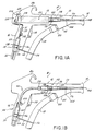
- Fig. 1A is a schematic view in partial crosssection of an electrostatic spray gun in accordance with the invention having an internal high voltage power supply mounted therein.
- Fig. 1B shows the electrostatic spray gun of Fig. 1A having the end section of a high voltage cable mounted within the gun.
- Fig. 2 is an exploded view of the components of the electrostatic spray guns of Figs. 1A and 1B.
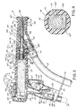
- Fig. 3 is a cross section of the electrostatic spray gun of Fig. 1A.
- Fig. 4 is a cross sectional view of the barrel of the gun taken along lines 4-4 of Fig. 3.
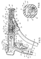
- Fig. 5 is a cross section of the electrostatic spray gun of Fig. 1B.
- Fig. 6 is a cross sectional view of the barrel of the gun taken along lines 6-6 of Fig. 5.
- Fig. 7 is a longitudinal cross section of the gun resistor housing
- Fig. 8 shows details of the gun resistor.
- FIG. 1A an electrostatic spray gun 10 configured to operate with an internal voltage multiplication circuit or internal voltage multiplier 20 is shown.
- Gun 10 has a pistol-shaped housing 12 with a barrel 13 terminating at a discharge end 14 and a handle 16.
- a conduit 18 brings the coating material to be charged into housing 12 proximate discharge end 14.
- Within housing 12 is an internal voltage multiplier 20 having a forward end 22 and a rearward end 24.
- Mounted to the forward end 22 of multiplier circuit 20 is an resistor/electrode assembly 26.
- a heat conductive band 28 comprised of a band of thermally conductive material and having a tab 29 extending therefrom, is mounted for the transfer of heat generated by internal voltage multiplier 20.
- a cable mounting collar 36 Secured by annular flanges and recesses in an aperture at the lower end 30 of handle 16 is a cable mounting collar 36 having a bore therein through which a low voltage power supply cable 32 extends.
- the portion of cable mounting collar 36 housed within handle 16 is surrounded by an insulating boot 37 that tapers to a narrow opening through which two groups of insulated conductors extend that terminate into a two-pin and a three-pin plug 38, 39, respectively.
- Plug 39 mates with plug 31 to provide an electrical connection from a remote low voltage power supply (not shown) to voltage multiplier 20.
- a low voltage dc source such as a battery located within the gun, could supply low voltage to internal voltage multiplier 20 through plug 31.
- FIG. 1B shows the electrostatic spray gun 10 of Fig. 1A configured to operate with an external high voltage power supply (not shown) using a high voltage cable 40 having one end connected to the external high voltage supply and the other end of the high voltage cable 40 mounted within gun 10.
- Gun 10 again includes a pistol-shaped housing 12 having a discharge end 14 and handle 16 with discharge end 14 being supplied coating material via conduit 18.
- Forward end 42 of high voltage cable 40 is connected to resistor/ electrode assembly 26 while rearward section 44 extends through a bore in cable mounting collar 46 to the external high voltage supply.
- cable mounting collar 46 is secured by annular flanges and recesses within an opening in lower end 30 of handle 16.
- An insulating boot 45 covers cable mounting collar 46 within handle 16.
- internal voltage multiplier 20 and externally supplied high voltage cable 40 reside in approximately the same location within housing 12 of gun 10.
- Handle 16 has two mateable sections 48 and 50 preferably constructed of electrically conductive, impact resilient plastic material such as carbon-filled nylon.
- Handle section 50 has a cable holder 52 in the form of an elongated flat metal plate having a rearward end 54 which is attached to lower end 30 of handle section 50 by screws or the like (not shown) and a distal end 56 extending outwardly from handle 16 which has an opening 57 through which conduit 18 (Fig. 3) passes.
- Cable holder end 54 has an opening 55 into which cable mounting collar 36 or 46 is secured depending upon whether a low voltage cable or a high voltage cable enters the lower end of the handle.
- Outside walls 68 and 70 of handle sections 48 and 50 are constructed to provide recessed areas 152 and 158 to collectively form an internal chamber in handle 16 when handle sections 48 and 50 are mated together.
- This internal chamber alternatively provides a) a passageway for low voltage cable 32 and a repository for rearward end 24 of internal voltage multiplier 20 when gun 10 is electrically supplied by an external low voltage dc source, or b) a passageway for high voltage cable 40 when gun 10 is supplied by an external high voltage source.
- Handle section 50 also includes an inverted L-shaped trigger 58 which is mounted at the free end of its base about a pivot pin 60 which is anchored to the handle section 50.
- Outer trigger end 62 lies adjacent a lever 66 extending from electrical switch 64 mounted to handle section 50 between trigger 58 and recessed area 158 in handle section 50. Pivoting trigger 58 about pin 60 pushes lever 66 towards switch 64 to open and close electrical switch 64.
- the opening and closing of switch 64 via trigger 58 controls the input of voltage to internal voltage multiplier 20 or the forward end 42 of high voltage cable 40, respectively.
- gun barrel 12 comprises an elongated sleeve 72 having an exterior polygonal shape.
- Sleeve 72 has a forward section 76 and a rearward section 74 having an internal bore which is rectangular in cross-section to receive either internal voltage multiplier 20 or forward end section of high voltage cable 40 in a manner discussed below.
- Rearward section 74 has a rearward area 82 which fits within recessed area 152 of handle sections 48 and 50 to extend the internal chamber in handle 16 into sleeve 72.
- Transverse wall 79 in reduced diameter extension 78 (shown in dotted lines) of barrel section 74 terminates the internal chamber.
- Attached by screws 83 (Figs. 3 and 5) in upper surface 84 of rearward section 82 is a support hook 86.
- Barrel portions 74 and 76 are preferably constructed of electrically nonconductive, impact resilient plastics while support hook 86 is preferably made from a thermally conductive material, such as aluminum, to assist in heat dissipation from the gun as is explained below.
- forward barrel section 76 is shown in place about extension 78 and secured to extension 78 by a set screw 80 or the like. Extending from the lower side of barrel section 76 is a material intake chute 95 that provides external access to the bore centrally located within barrel section 76. The bore within barrel section 76 communicates with the internal chamber extending into barrel section 74 through an opening 169 in transverse wall 79 of extension 78 in a manner described in greater detail below.
- Nozzle 96 has a rearward section 106 with a diameter that is less than the diameter of the bore in barrel section 76 and a forward section 107 that has an outside diameter approximately the same as the outside diameter of barrel section 76.
- An O-ring seal 102 located in annular groove 104 in rearward end 106 of nozzle 96 holds nozzle 96 in place at the forward end of barrel section 76 when rearward section 106 is inserted into the bore of barrel section 76 so forward section 107 of nozzle 96 abuts the forward end of barrel section 76.
- Fig. 2 further shows a tubular deflector stem 98 having a sloping nose 99 at its forward end.
- a portion of resistor/electrode assembly 26 extends from the forward end of deflector stem 98 to frictionally mount deflector 100.
- electrode 108 of resistor/electrode assembly 26 extends slightly beyond the large end of funnel-shaped deflector 100.
- a narrow opening 101 at the rearward end of funnel-shaped deflector 100 can be slid rearwardly over the extending end of resistor/electrode assembly 26 and is frictionally secured thereto.
- a passageway within deflector stem 98 has a stair-stepped diameter to coincide with the forward stair-stepped diameter segments of the tubular resistor/electrode assembly 26.
- internal voltage multiplier 20 has a rectangular body with heat conductive band 28 mounted at its rearward end 24 and a telescoping threaded front end having two segments 110 and 112.
- the electrical construction of internal voltage multiplier 20 is generally known within the art and may include a step-up transformer, an oscillator and a capacitor/diode cascade (all not shown) to provide a high voltage dc output to resistor/electrode assembly 26 from the low voltage input supplied to internal voltage multiplier 20 through the insulated conductor pair connected to three-pin plug 31.
- Threaded segment 110 is intermediate the forwardmost threaded segment 112 of internal voltage multiplier 20 and the front edge 168 of the rectangular body of voltage multiplier 20. Threaded segment 110 has an outside diameter greater than that of the rearmost segment 116 of resistor/electrode assembly 26 so when resistor/electrode assembly 26 is threaded onto threaded segment 112, segment 116 of resistor/ electrode assembly 26 abuts threaded segment 110.
- internal voltage multiplier 20 is placed within the internal chamber formed by recessed areas 152 in handle sections 48, 50 and which continues into rectangular chamber 167 of barrel section 74, front shoulder 168 of voltage multiplier 20 abuts internal wall 79 that extends transversely across the barrel interior at the forward end of the internal chamber (Fig.
- Figs. 3 and 4 show a cross section of the assembled gun 10 with internal voltage multiplier 20 mounted therein.
- the cross section of internal voltage multiplier 20 is substantially rectangular so internal voltage multiplier 20 does not rotate about its longitudinal axis within the inner volume of rear barrel section 74. This is done to prevent internal voltage multiplier 20 from rotating within barrel section 74 when retainer 124 is threaded onto and off of threaded extension 110 of internal voltage multiplier 20. Since internal voltage multiplier 20 cannot rotate within barrel section 74, internal voltage multiplier 20 remains mounted to wall 79 by retainer 124 to ensure the electrical contact between the high voltage output of internal voltage multiplier 20 and resistor/electrode assembly 26 is maintained.
- retainer 124 Forward end 126 of retainer 124 is precluded from engagement with front shoulder 117 of rearmost segment 116 of resistor/electrode assembly 26 to ensure that rear end 122 of retainer 124 engages wall 79.
- assembly 26 has internal threads 178 at its rear end which are threaded onto extension 112 at forward end 22 of internal voltage multiplier 20. In this manner, retainer 124 secures resistor/electrode assembly 26 and internal voltage multiplier 20 within gun 10 to protect the electrical connection between these two components.
- Cable retaining plug 118 shown in Fig. 2, is constructed in a similar fashion to the forward section of internal voltage multiplier 20 to nonrotationally fit within the internal chamber 167 of barrel section 74.
- Cable retaining plug 118 includes a tubular nonconductive body having a stair-stepped outside diameter and has a threaded forward end 42 that corresponds in function to the threaded forward end 22 of internal voltage multiplier 20.
- end 42 includes a large threaded extension 110a and a second smaller threaded extension 112a.
- the plug 118 also has a rearward threaded end 120, and an electrical conductor (not shown) snugly secured within a centrally located bore extending between the two threaded ends 42, 120.
- Retaining plug 118 is connected to high voltage cable 40 by cable nut 114 which is concentrically mounted at the forward end of high voltage cable 40.
- cable nut 114 By threading cable nut 114 about threaded end 120 of retaining plug 118, an electrical path is established between the forward end 42 of the conductor located within retaining plug 118 to the external high voltage source via the high voltage cable 40 and the conductor within retainer plug 118.
- resistor/electrode assembly 26 is mounted to forward end 42 in the same manner as it was to forward end 22 of voltage multiplier 20, the high voltage output present at the forward end of the conductor within plug 118 is conducted to electrode 108 via the gun resistor within assembly 26.
- cable retaining plug 118 has a rectangular cross-section collar 125 being configured to fit within internal chamber 167 as did the body of internal voltage multiplier 20.
- the high voltage cable is operatively positioned in the gun by locating cable mounting collar 46 within annular groove 156 of handle section 50, positioning high voltage cable 40 within the internal chamber of handle 16 and rearward barrel section 74, and inserting threaded extension 110a of end 42 through opening 169 of wall 79.
- Plug 118 is held against rotation by the interfit of the similarly shaped collar 125 and the internal chamber 167 of barrel section 74. In this position, rectangular collar 125 abuts wall 79 just as front shoulder 168 does when internal voltage multiplier 20 is placed within the internal chamber.
- Fig. 3 shows an assembled electrostatic spray gun 10 with internal voltage multiplier 20 mounted therein.
- Electrical plug 38 is connected to electrical plug 59 whose insulated conductor leads to electrical switch 64 so the input of voltage from the external low dc voltage source supplied through cable 32 may be controlled via trigger 58.
- Electrical plug 39 is connected to three-pin plug 31 to provide the low dc voltage input to internal voltage multiplier 20.
- Internal voltage multiplier 20 is placed within recessed portion 152 of handle section 50 so that hole 154 of tab 29 extending from heat conductive band 28 aligns with hole 90 of handle section 50.
- Rear barrel section 74 is placed about internal voltage multiplier 20 so hole 88 of hook support 86 is aligned with holes 154 and 90.
- Annular flange 138 of cable mounting collar 36 is placed within groove 156 and the insulated conductive leads extending from cable 32 through mounting collar 36 are placed within the recessed area 158 of handle section 50.
- Handle section 48 is placed over handle section 50 so that screws 94, 160 and 162 extend to and are received by holes 90, 164, and 166 in handle section 50 (Fig. 2), respectively. Screws 94, 160 and 162 secure handle sections 48 and 50 about cable mounting collar 36 and reduced diameter section 82 of rear barrel section 74.
- Heat conductive band 28 is thus thermally connected to support hook 86 so heat produced by internal voltage multiplier 20 is conducted through heat conductive band 28 and tab 29 to support hook 86 and from there the heat is dissipated into the surrounding air.
- the assembled gun of Fig. 3 further shows resistor/electrode assembly 26 screwed onto forward end 22 of internal voltage multiplier 20 and retainer 124 secured onto the threads of extension 110 about the base of resistor/electrode assembly 26 to mount internal voltage multiplier 20 to wall 79 within rear barrel section 74.
- Forward barrel section 76 frictionally grips extension 78 with O-ring seal 119 mounted within annular groove 121 located on extension 78 of barrel section 74 at its rearward end.
- Barrel section 76 is secured about extension 78 with set screw 80.
- Conduit 18 is inserted through the opening 57 at distal end 56 of cable holder 52 and connected to conduit connector 109 held within material intake chute 95 by O-ring seal 111.
- Nozzle 96 is seated within forward barrel section 76 so that O-ring seal 102 engages the internal walls of forward barrel section 76.
- Deflector stem 98 is installed on the outside diameter of resistor/electrode assembly 26 and frictionally secured thereon by O-ring seal 128.
- Deflector 100 is frictionally slid onto resistor/ electrode assembly 26 into abutment with sloping nose 99 to complete the assembly of gun 10.
- Deflector 100 is frictionally held in place by an O-ring seal 130 mounted within deflector 100.
- Gun 10 may be reassembled with the high voltage cable as shown in Fig. 5.
- cable retainer plug 118 is screwed onto high voltage cable 40 with nut 114 and high voltage cable 40 is placed within the recessed portions of handle section 50 so that annular flange 200 of cable mounting collar 46 rests within annular groove 156 of handle 16.
- Rear barrel section 74 is placed about high voltage cable 40 so forward threaded end 42 of cable plug 118 extends into extension 78 and hole 88 of hook support 86 aligns with hole 90 of handle section 50.
- Trigger plug 150 extending from high voltage cable 40 is attached to electrical plug 59 whose insulated conductor is connected to electrical switch 64.
- Handle section 48 is placed over handle section 50 so that screws 94, 160 and 162 (Fig.
- Conduit 18 is slid through opening 57 in the end 56 of cable holder 52 and connected to conduit connector 109.
- Nozzle 96, deflector stem 98 and deflector 100 are assembled in the forward end of barrel section 76 as previously described for the assembled gun shown in Fig. 3.
- the electrostatic spray gun 10 is now powered remotely from a high voltage dc power supply through high voltage supply cable 40.
- the only components differing from the assembled gun of Fig. 5 and the assembled gun with the internal voltage multiplier 20 shown in Fig. 3 are those associated with the alternative high voltage sources. In this fashion, handle sections 48, 50, hook member 86, barrel sections 74, 76, resistor assembly 26, nozzle 96 and deflector elements 98 and 100 are the same regardless of the nature of the high voltage source used.
- Fig. 7 shows in more detail the connection of resistor/electrode assembly 26 to forward end 22 of internal voltage multiplier 20.
- Resistor/electrode assembly 26 has a tubular resistor housing 174 having a stair-stepped outside diameter.
- O-ring seal 128 is mounted within annular groove 129 in resistor housing 174 to grip deflector stem 98 when the nozzle of gun 10 is assembled.
- Resistor structure 176 lies within cylindrical cavity 172 of resistor housing 174.
- Electrode module 108 has a non-conductive electrode mount 108a secured about electrode 108b that extends forwardly and rearwardly of electrode mount 108a. Module 108 is threadably secured to housing 174 by threads 108c.
- Resistor/electrode assembly 26 is constructed by filling cavity 172 of the tubular resistor housing 174 with dielectric grease and inserting resistor structure 176 into cavity 172 from end 178 having the larger opening. Cavity 180 in forward end 22 of internal voltage multiplier 20 is filled with dielectric grease and conductive spring 182 is inserted into cavity 180 and resistor holder 174 screwed onto threads 112 of forward end 22 of internal voltage multiplier 20. As resistor/electrode assembly 26 is tightened onto the forward end of internal voltage multiplier 20, spring 182 is compressed to insure a solid electrical connection is made between internal voltage multiplier 20 and resistor structure 176.
- the dielectric grease evacuates the air from the cavities 172 and 180 to prevent any dielectric breakdown of air within either cavity that would produce arcing and eventually short out the internal voltage multiplier 20.
- Electrode module 108 is screwed onto the narrow forward end of resistor holder 174 so the rearwardly extending end of electrode 108b makes a solid electrical contact with resistor structure 176 to complete resistor/electrode assembly 26.
- the dielectric grease is preferably of the type such as that denoted by Part No. PE-PJ Code 4562 which is manufactured by Penreco of Butler, PA.
- Forward end 42 of cable plug 118 is constructed in substantially the same manner as forward end 22 of internal voltage multiplier 20 to permit the same connection of resistor/electrode assembly 26 to high voltage cable retaining plug 40.
- Fig. 8 shows the resistor structure 176 that is inserted in resistor holder 174 to form resistor/electrode assembly 26.
- Gun resistors 184,a,b,c,d have caps 186 at each end with the two forwardmost resistors 184c,d being rigidly connected to one another.
- the connections between the remaining resistors 184 are made by soldering conductive springs 188 between successive resistor caps 186.
- Compression spring 182 is soldered to the rearmost resistor 184a.
- the connecting springs 188 reduce the risk of breakage caused by any side loading upon the resistor structure.
Abstract
Description
- This invention relates to electrostatic spray guns for electrostatically charging coating material emitted therefrom.
- Electrostatic spray guns used for charging particles of a coating material emitted from the gun are well known. To attract the coating material to the article to be covered, the coating particles are charged to the opposite polarity of the article to be coated. Early forms of electrostatic spray guns were powered from remote high-voltage dc supplies that provided output voltages of 70 kilovolts (KV) or higher. The output voltage of such power supplies was conducted via high voltage cables to particle-charging electrodes mounted proximate the nozzles of the guns. These high voltage cables typically were stiff, making the gun difficult to maneuver, and stored potentially dangerous levels of electrical energy which created shock and ignition hazards.
- To provide a safer and more maneuverable gun, miniaturized voltage multiplier circuits operating at high frequency were developed that could fit within the electrostatic spray gun to produce the requisite high dc charging voltage from a relatively low input voltage. Such guns with internal high voltage multiplication capabilities are generally powered from either an external low voltage power supply via a low voltage cable to the gun which is more flexible than high voltage cables, or a low voltage power supply, such as a battery, located within the gun which eliminates a cable altogether. The internal high voltage circuit steps up the low input voltage by means of a transformer, rectifies and multiplies the stepped-up voltage in a diode/capacitor multiplier cascade, and outputs a high dc voltage to the particle-charging electrode of the gun.
- Electrostatic guns with internal voltage multiplier circuits are particularly advantageous for manual spray coating applications since the guns are more maneuverable than guns supplied from external high voltage power supplies having stiff and bulky high voltage cables. However, maneuverability is not generally a consideration in applications where the gun is robot-controlled or machine-reciprocated, and as a consequence in such installations it is common to use external high voltage power supplies.
- Historically, electrostatic spray gun manufacturers marketing both manual and robot-controlled or machine-reciprocated guns had to manufacture guns of entirely different construction for these two different applications. The additional tooling and parts inventory required to support the manufacture of two different gun constructions unnecessarily increased the cost of gun manufacture.
- An electrostatic spray gun in accordance with the invention for electrostatically charging coating material emitted from the nozzle thereof comprises a housing having an internal chamber capable of housing either: (a) an internal voltage multiplication circuit powered from a remote external low voltage source for producing high dc voltage at its output, or (b) the end section of a high voltage cable powered from a remote external high voltage source; securing means being provided for securing either an integral voltage multiplication circuit or an end section of a high voltage cable within the internal chamber to a charging electrode via electric circuit means.
- Such an arrangement provides a single electrostatic spray gun construction that can be alternatively powered from either a high voltage external supply or an internal voltage multiplier circuit fed from an external low voltage source. Such a spray gun has a common set of gun parts which are used in either mode, so only the power supply components need be changed. It may also incorporate modular electrical components for quick disassembly, insertion of the desired form of power supply, and reassembly.
- Suitably the electric circuit means may include at least one resistor and is in the form of an integral unit.
- Advantageously, in an electronic spray gun where a voltage multiplication circuit is located within the chamber, a thermally conductive heat dissipation member may be provided having a substantial portion thereof located outside the housing and having an integral mounting member in contact with the housing, a thermally conductive band may be provided surrounding at least a portion of the voltage multiplication circuit and having a thermally conductive tab extending therefrom, and means may be provided to connect the thermally conductive band in head transfer relation to the thermally conductive heat dissipation member.
- The tab extending from the heat conductive band may be connected to the heat dissipation member by a fastener that also secures the heat dissipation member to the gun housing.
- A bore may be provided within the housing and separated from the forward portion of the chamber by a transverse wall, the wall having an aperture therein so that the forward portion of the chamber communicates with the bore, the rearward end of the electric circuit means being mountable either to the forward end of the voltage multiplication circuit or to the end section of the high voltage cable extending through the aperture thereby electrically connecting the electric circuit means to one of the voltage multiplication circuit or the end section of the high voltage cable, and retaining means are provided abutting the wall to engage either the forward end of the voltage multiplication circuit or the end section of the high voltage cable to maintain the electrical connection to the electric circuit means.
- An electrostatic spray gun for electronically charging coating material emitted from the nozzle thereof comprising a housing having an internal chamber and a voltage multiplication circuit mounted within the chamber may have a thermally conductive band located within the chamber to collect heat generated by the voltage multiplication circuit, the band being in heat transfer relation thereto and having a tab extending therefrom, heat dissipation means being mounted to the housing and having a substantial portion thereof located outside the housing, and means being provided to connect the tab to the heat dissipation means to transfer to the environment heat collected within the chamber generated by the voltage multiplication circuit.
- Detachable mounting means may be provided forward of the chamber for detachably mounting either the voltage multiplication circuit or the end section of a high voltage cable within the housing.
- Interlocking means may be mounted to each of the voltage multiplication circuit and the end section of the high voltage cable to prevent rotation of either the voltage multiplication circuit or the end section of the high voltage cable relative to the chamber. Suitably, the interlocking means may be in the form of a retaining plug.
- The gun housing may have a barrel connected thereto, or formed as a part of the housing, the housing being located at the end of the barrel. The barrel contains the forward end of the internal chamber and is separated from a bore located forward of the internal chamber by a divider wall having an opening therein. The rearward end of a gun resistor/electrode assembly may be mounted to the forward end of either the end section of the high voltage cable or the internal voltage multiplier extending into the bore through the opening in the wall. The rearward end of a retaining member located forward of the divider wall engages the forwardmost portion or tip of the end section of the high voltage cable or the high voltage output of the internal voltage multiplier, as the case may be, which extends into the bore through the divider wall, thereby releasably retaining the high voltage cable end section or the multiplier circuit within the internal chamber. Since the high voltage cable end section or voltage multiplier, and the resistor/electrode assembly mounted thereon are fixed relative the divider wall, the electrical connection between the gun resistor/electrode assembly and the high voltage output of either the cable or the internal multiplier circuit is maintained.
- Embodiments of an electrostatic spray gun constructed in accordance with the invention use the same housing with internal chamber, retainer, gun resistor and discharge electrode, trigger, and nozzle regardless of whether the high voltage cable or internal voltage multiplier is used. By using the same gun construction for both high voltage type guns, the parts inventory is materially reduced from that previously required when different gun constructions were used for the different type of guns.
- The invention will now be described by way of example with reference to the accompanying drawings, in which:
- Fig. 1A is a schematic view in partial crosssection of an electrostatic spray gun in accordance with the invention having an internal high voltage power supply mounted therein.
- Fig. 1B shows the electrostatic spray gun of Fig. 1A having the end section of a high voltage cable mounted within the gun.
- Fig. 2 is an exploded view of the components of the electrostatic spray guns of Figs. 1A and 1B.
- Fig. 3 is a cross section of the electrostatic spray gun of Fig. 1A.
- Fig. 4 is a cross sectional view of the barrel of the gun taken along lines 4-4 of Fig. 3.
- Fig. 5 is a cross section of the electrostatic spray gun of Fig. 1B.
- Fig. 6 is a cross sectional view of the barrel of the gun taken along lines 6-6 of Fig. 5.
- Fig. 7 is a longitudinal cross section of the gun resistor housing,
- Fig. 8 shows details of the gun resistor.
- In Fig. 1A, an
electrostatic spray gun 10 configured to operate with an internal voltage multiplication circuit orinternal voltage multiplier 20 is shown. Gun 10 has a pistol-shaped housing 12 with abarrel 13 terminating at adischarge end 14 and ahandle 16. Aconduit 18 brings the coating material to be charged intohousing 12proximate discharge end 14. Withinhousing 12 is aninternal voltage multiplier 20 having aforward end 22 and arearward end 24. Mounted to theforward end 22 ofmultiplier circuit 20 is an resistor/electrode assembly 26. At therearward end 24 ofinternal voltage multiplier 20, a heatconductive band 28 comprised of a band of thermally conductive material and having atab 29 extending therefrom, is mounted for the transfer of heat generated byinternal voltage multiplier 20. - Extending from the rear of internal voltage multiplier 20 in Fig. 1A are three insulated conductors that are connected to a three
pin plug 31. Secured by annular flanges and recesses in an aperture at thelower end 30 ofhandle 16 is acable mounting collar 36 having a bore therein through which a low voltagepower supply cable 32 extends. The portion ofcable mounting collar 36 housed withinhandle 16 is surrounded by aninsulating boot 37 that tapers to a narrow opening through which two groups of insulated conductors extend that terminate into a two-pin and a three-pin plug plug 31 to provide an electrical connection from a remote low voltage power supply (not shown) tovoltage multiplier 20. Alternatively, a low voltage dc source, such as a battery located within the gun, could supply low voltage to internal voltage multiplier 20 throughplug 31. - Using like numerals for like structural elements, Fig. 1B shows the
electrostatic spray gun 10 of Fig. 1A configured to operate with an external high voltage power supply (not shown) using ahigh voltage cable 40 having one end connected to the external high voltage supply and the other end of thehigh voltage cable 40 mounted withingun 10. Gun 10 again includes a pistol-shaped housing 12 having adischarge end 14 and handle 16 withdischarge end 14 being supplied coating material viaconduit 18. Forward end 42 ofhigh voltage cable 40 is connected to resistor/electrode assembly 26 whilerearward section 44 extends through a bore incable mounting collar 46 to the external high voltage supply. Likecable mounting collar 36,cable mounting collar 46 is secured by annular flanges and recesses within an opening inlower end 30 ofhandle 16. An insulatingboot 45 coverscable mounting collar 46 withinhandle 16. As can be seen in the comparison of Figs. 1A and 1B,internal voltage multiplier 20 and externally suppliedhigh voltage cable 40 reside in approximately the same location withinhousing 12 ofgun 10. - Referring now to Fig. 2, the various components of
electrostatic spray gun 10 are explained.Handle 16 has twomateable sections Handle section 50 has acable holder 52 in the form of an elongated flat metal plate having arearward end 54 which is attached tolower end 30 ofhandle section 50 by screws or the like (not shown) and adistal end 56 extending outwardly fromhandle 16 which has anopening 57 through which conduit 18 (Fig. 3) passes.Cable holder end 54 has anopening 55 into whichcable mounting collar walls handle sections areas handle 16 whenhandle sections low voltage cable 32 and a repository forrearward end 24 ofinternal voltage multiplier 20 whengun 10 is electrically supplied by an external low voltage dc source, or b) a passageway forhigh voltage cable 40 whengun 10 is supplied by an external high voltage source.Handle section 50 also includes an inverted L-shapedtrigger 58 which is mounted at the free end of its base about apivot pin 60 which is anchored to thehandle section 50.Outer trigger end 62 lies adjacent alever 66 extending fromelectrical switch 64 mounted to handlesection 50 betweentrigger 58 and recessedarea 158 inhandle section 50. Pivotingtrigger 58 aboutpin 60 pusheslever 66 towardsswitch 64 to open and closeelectrical switch 64. When the insulated conductor pair ending in two-pin plug 59 that extends fromswitch 64 is connected to plug 38 oflow voltage cable 32 or two-pin plug 150 ofhigh voltage cable 40, depending upon which cable is used, the opening and closing ofswitch 64 viatrigger 58 controls the input of voltage tointernal voltage multiplier 20 or theforward end 42 ofhigh voltage cable 40, respectively. - Further referring to Fig. 2,
gun barrel 12 comprises anelongated sleeve 72 having an exterior polygonal shape.Sleeve 72 has aforward section 76 and arearward section 74 having an internal bore which is rectangular in cross-section to receive eitherinternal voltage multiplier 20 or forward end section ofhigh voltage cable 40 in a manner discussed below.Rearward section 74 has arearward area 82 which fits within recessedarea 152 ofhandle sections handle 16 intosleeve 72.Transverse wall 79 in reduced diameter extension 78 (shown in dotted lines) ofbarrel section 74 terminates the internal chamber. Attached by screws 83 (Figs. 3 and 5) inupper surface 84 ofrearward section 82 is asupport hook 86. When reducedsection 82 is placed betweenhandle sections hole 88 insupport hook 86 and holes 90 and 92 inhandle sections handle sections barrel section 74.Barrel portions support hook 86 is preferably made from a thermally conductive material, such as aluminum, to assist in heat dissipation from the gun as is explained below. - Again with reference to Fig. 2,
forward barrel section 76 is shown in place aboutextension 78 and secured toextension 78 by aset screw 80 or the like. Extending from the lower side ofbarrel section 76 is amaterial intake chute 95 that provides external access to the bore centrally located withinbarrel section 76. The bore withinbarrel section 76 communicates with the internal chamber extending intobarrel section 74 through anopening 169 intransverse wall 79 ofextension 78 in a manner described in greater detail below.Nozzle 96 has arearward section 106 with a diameter that is less than the diameter of the bore inbarrel section 76 and aforward section 107 that has an outside diameter approximately the same as the outside diameter ofbarrel section 76. An O-ring seal 102 located inannular groove 104 inrearward end 106 ofnozzle 96 holdsnozzle 96 in place at the forward end ofbarrel section 76 whenrearward section 106 is inserted into the bore ofbarrel section 76 soforward section 107 ofnozzle 96 abuts the forward end ofbarrel section 76. - Fig. 2 further shows a
tubular deflector stem 98 having a sloping nose 99 at its forward end. A portion of resistor/electrode assembly 26 extends from the forward end of deflector stem 98 to frictionallymount deflector 100. When assembled,electrode 108 of resistor/electrode assembly 26 extends slightly beyond the large end of funnel-shapeddeflector 100. Anarrow opening 101 at the rearward end of funnel-shapeddeflector 100 can be slid rearwardly over the extending end of resistor/electrode assembly 26 and is frictionally secured thereto. A passageway withindeflector stem 98 has a stair-stepped diameter to coincide with the forward stair-stepped diameter segments of the tubular resistor/electrode assembly 26. By pushing the forward end of resistor/electrode assembly 26 intoopening 103 at the rearward end ofdeflector stem 98, the deflector stem is frictionally secured about resistor/electrode assembly 26. - As shown in Fig. 2,
internal voltage multiplier 20 has a rectangular body with heatconductive band 28 mounted at itsrearward end 24 and a telescoping threaded front end having twosegments internal voltage multiplier 20 is generally known within the art and may include a step-up transformer, an oscillator and a capacitor/diode cascade (all not shown) to provide a high voltage dc output to resistor/electrode assembly 26 from the low voltage input supplied tointernal voltage multiplier 20 through the insulated conductor pair connected to three-pin plug 31. - Threaded
segment 110 is intermediate the forwardmost threadedsegment 112 ofinternal voltage multiplier 20 and thefront edge 168 of the rectangular body ofvoltage multiplier 20. Threadedsegment 110 has an outside diameter greater than that of therearmost segment 116 of resistor/electrode assembly 26 so when resistor/electrode assembly 26 is threaded onto threadedsegment 112,segment 116 of resistor/electrode assembly 26 abuts threadedsegment 110. Wheninternal voltage multiplier 20 is placed within the internal chamber formed by recessedareas 152 inhandle sections rectangular chamber 167 ofbarrel section 74,front shoulder 168 ofvoltage multiplier 20 abutsinternal wall 79 that extends transversely across the barrel interior at the forward end of the internal chamber (Fig. 4) and threadedextensions internal voltage multiplier 20 extend through theopening 169 in wall 79 (Fig. 4) intoextension 78.Tubular retainer 124 having an interiorly threadedrearward end 122 is slid along resistor/electrode assembly 26 mounted to threadedextension 112 until the inner threads ofretainer 124 engage the outer threads of threadedextension 110.Retainer 124 is turned onto threadedextension 110 untilrear end 122 ofretainer 124 engages the forward face ofinternal wall 79. Thus assembled,internal voltage multiplier 20 is mounted to wall 79 to securevoltage multiplier 20 and resistor/electrode assembly 26 withingun 10. - Figs. 3 and 4 show a cross section of the assembled
gun 10 withinternal voltage multiplier 20 mounted therein. The cross section ofinternal voltage multiplier 20 is substantially rectangular sointernal voltage multiplier 20 does not rotate about its longitudinal axis within the inner volume ofrear barrel section 74. This is done to preventinternal voltage multiplier 20 from rotating withinbarrel section 74 whenretainer 124 is threaded onto and off of threadedextension 110 ofinternal voltage multiplier 20. Sinceinternal voltage multiplier 20 cannot rotate withinbarrel section 74,internal voltage multiplier 20 remains mounted to wall 79 byretainer 124 to ensure the electrical contact between the high voltage output ofinternal voltage multiplier 20 and resistor/electrode assembly 26 is maintained. Forward end 126 ofretainer 124 is precluded from engagement withfront shoulder 117 ofrearmost segment 116 of resistor/electrode assembly 26 to ensure thatrear end 122 ofretainer 124 engageswall 79. To prevent axial displacement of resistor/electrode assembly 26,assembly 26 hasinternal threads 178 at its rear end which are threaded ontoextension 112 atforward end 22 ofinternal voltage multiplier 20. In this manner,retainer 124 secures resistor/electrode assembly 26 andinternal voltage multiplier 20 withingun 10 to protect the electrical connection between these two components. -
Cable retaining plug 118, shown in Fig. 2, is constructed in a similar fashion to the forward section ofinternal voltage multiplier 20 to nonrotationally fit within theinternal chamber 167 ofbarrel section 74.Cable retaining plug 118 includes a tubular nonconductive body having a stair-stepped outside diameter and has a threadedforward end 42 that corresponds in function to the threaded forward end 22 ofinternal voltage multiplier 20. Specifically, end 42 includes a large threadedextension 110a and a second smaller threadedextension 112a. Theplug 118 also has a rearward threadedend 120, and an electrical conductor (not shown) snugly secured within a centrally located bore extending between the two threaded ends 42, 120. Retainingplug 118 is connected tohigh voltage cable 40 bycable nut 114 which is concentrically mounted at the forward end ofhigh voltage cable 40. By threadingcable nut 114 about threadedend 120 of retainingplug 118, an electrical path is established between theforward end 42 of the conductor located within retainingplug 118 to the external high voltage source via thehigh voltage cable 40 and the conductor withinretainer plug 118. When resistor/electrode assembly 26 is mounted toforward end 42 in the same manner as it was to forward end 22 ofvoltage multiplier 20, the high voltage output present at the forward end of the conductor withinplug 118 is conducted toelectrode 108 via the gun resistor withinassembly 26. - Between threaded ends 120, 42,
cable retaining plug 118 has arectangular cross-section collar 125 being configured to fit withininternal chamber 167 as did the body ofinternal voltage multiplier 20. The high voltage cable is operatively positioned in the gun by locatingcable mounting collar 46 withinannular groove 156 ofhandle section 50, positioninghigh voltage cable 40 within the internal chamber ofhandle 16 andrearward barrel section 74, and inserting threadedextension 110a ofend 42 throughopening 169 ofwall 79.Plug 118 is held against rotation by the interfit of the similarly shapedcollar 125 and theinternal chamber 167 ofbarrel section 74. In this position,rectangular collar 125 abutswall 79 just asfront shoulder 168 does wheninternal voltage multiplier 20 is placed within the internal chamber. Whenretainer 124 is threaded onto threadedextension 110a ofcable retaining plug 118 which corresponds in function to threadedextension 110 ofinternal voltage multiplier 20,cable retaining plug 118 and resistor/electrode assembly 26 are maintained in fixed axial relation to wall 79 to prevent uncoupling the forward end of retainingplug 118 and the rearward end of resistor/electrode assembly 26 (Fig. 6) thereby insuring continued electrical connection between the conductor withinplug 118 and the gun resistor. - The similarity in construction of the forward portion of retaining
plug 118 and the forward section ofinternal voltage multiplier 20permits gun 10, and in particular the gun electrode, to be alternatively provided with high dc voltage from either an external high dc voltage power supply viahigh voltage cable 40 or aninternal voltage multiplier 20 having a high dc voltage output. - Fig. 3 shows an assembled
electrostatic spray gun 10 withinternal voltage multiplier 20 mounted therein.Electrical plug 38 is connected toelectrical plug 59 whose insulated conductor leads toelectrical switch 64 so the input of voltage from the external low dc voltage source supplied throughcable 32 may be controlled viatrigger 58.Electrical plug 39 is connected to three-pin plug 31 to provide the low dc voltage input tointernal voltage multiplier 20.Internal voltage multiplier 20 is placed within recessedportion 152 ofhandle section 50 so thathole 154 oftab 29 extending from heatconductive band 28 aligns withhole 90 ofhandle section 50.Rear barrel section 74 is placed aboutinternal voltage multiplier 20 sohole 88 ofhook support 86 is aligned withholes Annular flange 138 ofcable mounting collar 36 is placed withingroove 156 and the insulated conductive leads extending fromcable 32 through mountingcollar 36 are placed within the recessedarea 158 ofhandle section 50.Handle section 48 is placed overhandle section 50 so thatscrews holes Screws secure handle sections cable mounting collar 36 and reduceddiameter section 82 ofrear barrel section 74. Heatconductive band 28 is thus thermally connected to supporthook 86 so heat produced byinternal voltage multiplier 20 is conducted through heatconductive band 28 andtab 29 to supporthook 86 and from there the heat is dissipated into the surrounding air. - The assembled gun of Fig. 3 further shows resistor/
electrode assembly 26 screwed ontoforward end 22 ofinternal voltage multiplier 20 andretainer 124 secured onto the threads ofextension 110 about the base of resistor/electrode assembly 26 to mountinternal voltage multiplier 20 to wall 79 withinrear barrel section 74.Forward barrel section 76frictionally grips extension 78 with O-ring seal 119 mounted withinannular groove 121 located onextension 78 ofbarrel section 74 at its rearward end.Barrel section 76 is secured aboutextension 78 withset screw 80.Conduit 18 is inserted through theopening 57 atdistal end 56 ofcable holder 52 and connected toconduit connector 109 held withinmaterial intake chute 95 by O-ring seal 111.Nozzle 96 is seated withinforward barrel section 76 so that O-ring seal 102 engages the internal walls offorward barrel section 76. Deflector stem 98 is installed on the outside diameter of resistor/electrode assembly 26 and frictionally secured thereon by O-ring seal 128.Deflector 100 is frictionally slid onto resistor/electrode assembly 26 into abutment with sloping nose 99 to complete the assembly ofgun 10.Deflector 100 is frictionally held in place by an O-ring seal 130 mounted withindeflector 100. To disassemblegun 10 withinternal voltage multiplier 20 mounted therein, the gun components are removed in reverse order. -
Gun 10 may be reassembled with the high voltage cable as shown in Fig. 5. To so assemblegun 10,cable retainer plug 118 is screwed ontohigh voltage cable 40 withnut 114 andhigh voltage cable 40 is placed within the recessed portions ofhandle section 50 so that annular flange 200 ofcable mounting collar 46 rests withinannular groove 156 ofhandle 16.Rear barrel section 74 is placed abouthigh voltage cable 40 so forward threadedend 42 ofcable plug 118 extends intoextension 78 andhole 88 ofhook support 86 aligns withhole 90 ofhandle section 50.Trigger plug 150 extending fromhigh voltage cable 40 is attached toelectrical plug 59 whose insulated conductor is connected toelectrical switch 64.Handle section 48 is placed overhandle section 50 so thatscrews cable mounting collar 46 and the reduceddiameter section 82 ofbarrel section 74 between them.Collar 125 ofcable plug 118 rests againstwall 79 withinrear barrel section 74 andforward end 42 extends intoextension 78. Resistor/electrode assembly 26 is screwed ontoforward end 42 ofplug 118 andretainer 124 is screwed onto threadedextension 110a ofplug 118 at the base of resistor/electrode assembly 26 to secureplug 118 and the forward end ofhigh voltage cable 40 to wall 79 withininternal chamber 167.Forward barrel section 76 is placed aboutextension 78 so O-ring seal 119grips extension 78 and setscrew 80 is tightened to securebarrel portions Conduit 18 is slid throughopening 57 in theend 56 ofcable holder 52 and connected toconduit connector 109.Nozzle 96,deflector stem 98 anddeflector 100 are assembled in the forward end ofbarrel section 76 as previously described for the assembled gun shown in Fig. 3. Theelectrostatic spray gun 10 is now powered remotely from a high voltage dc power supply through highvoltage supply cable 40. The only components differing from the assembled gun of Fig. 5 and the assembled gun with theinternal voltage multiplier 20 shown in Fig. 3 are those associated with the alternative high voltage sources. In this fashion, handlesections hook member 86,barrel sections resistor assembly 26,nozzle 96 anddeflector elements - Fig. 7 shows in more detail the connection of resistor/
electrode assembly 26 to forward end 22 ofinternal voltage multiplier 20. Resistor/electrode assembly 26 has atubular resistor housing 174 having a stair-stepped outside diameter. O-ring seal 128 is mounted withinannular groove 129 inresistor housing 174 to gripdeflector stem 98 when the nozzle ofgun 10 is assembled.Resistor structure 176 lies withincylindrical cavity 172 ofresistor housing 174.Electrode module 108 has anon-conductive electrode mount 108a secured about electrode 108b that extends forwardly and rearwardly ofelectrode mount 108a.Module 108 is threadably secured tohousing 174 bythreads 108c. - Resistor/
electrode assembly 26 is constructed by fillingcavity 172 of thetubular resistor housing 174 with dielectric grease and insertingresistor structure 176 intocavity 172 fromend 178 having the larger opening.Cavity 180 inforward end 22 ofinternal voltage multiplier 20 is filled with dielectric grease andconductive spring 182 is inserted intocavity 180 andresistor holder 174 screwed ontothreads 112 offorward end 22 ofinternal voltage multiplier 20. As resistor/electrode assembly 26 is tightened onto the forward end ofinternal voltage multiplier 20,spring 182 is compressed to insure a solid electrical connection is made betweeninternal voltage multiplier 20 andresistor structure 176. The dielectric grease evacuates the air from thecavities internal voltage multiplier 20.Electrode module 108 is screwed onto the narrow forward end ofresistor holder 174 so the rearwardly extending end of electrode 108b makes a solid electrical contact withresistor structure 176 to complete resistor/electrode assembly 26. The dielectric grease is preferably of the type such as that denoted by Part No. PE-PJ Code 4562 which is manufactured by Penreco of Butler, PA. Forward end 42 ofcable plug 118 is constructed in substantially the same manner asforward end 22 ofinternal voltage multiplier 20 to permit the same connection of resistor/electrode assembly 26 to high voltagecable retaining plug 40. - Fig. 8 shows the
resistor structure 176 that is inserted inresistor holder 174 to form resistor/electrode assembly 26. Gun resistors 184,a,b,c,d, havecaps 186 at each end with the twoforwardmost resistors 184c,d being rigidly connected to one another. The connections between the remaining resistors 184 are made by solderingconductive springs 188 between successive resistor caps 186.Compression spring 182 is soldered to therearmost resistor 184a. The connectingsprings 188 reduce the risk of breakage caused by any side loading upon the resistor structure.
Claims (10)
- An electrostatic spray gun for electrostatically charging coating material emitted from the nozzle thereof comprising a housing having an internal chamber capable of housing either: (a) an internal voltage multiplication circuit powered from a remote external low voltage source for producing high dc voltage at its output, or (b) the end section of a high voltage cable powered from a remote external high voltage source; securing means being provided for securing either an integral voltage multiplication circuit or an end section of a high voltage cable within the internal chamber to a charging electrode via electric circuit means.
- An electrostatic spray gun according to Claim 1 characterised in that the electric circuit means includes at least one resistor and is in the form of an integral unit.
- An electrostatic spray gun according to Claim 1 or 2 wherein a voltage multiplication circuit is located within the chamber, characterised in that a thermally conductive heat dissipation member is provided having a substantial portion thereof located outside the housing and having an integral mounting member in contact with the housing, a thermally conductive band is provided surrounding at least a portion of the voltage multiplication circuit and having a thermally conductive tab extending therefrom, and in that means are provided to connect the thermally conductive band in heat transfer relation to the thermally conductive heat dissipation member.
- An electrostatic spray gun according to Claim 1,2 or 3 characterised in that a bore is provided within the housing and is separated from the forward portion of the chamber by a transverse wall, the wall having an aperture therein so that the forward portion of the chamber communicates with the bore, in that the rearward end of the electric circuit means is mountable either to the forward end of voltage multiplication circuit or to the end section of the high voltage cable extending through the aperture thereby electrically connecting the electric circuit means to one of the voltage multiplication circuit or the end section of the high voltage cable, and in that retaining means are provided abutting the wall to engage either the forward end of the voltage multiplication circuit or the end section of the high voltage cable to maintain the electrical connection to the electric circuit means.
- An electrostatic spray gun for electrostatically charging coating material emitted from the nozzle thereof comprising a housing having an internal chamber and a voltage multiplication circuit mounted within the chamber, characterised in that a thermally conductive band is located within the chamber to collect heat generated by the voltage multiplication circuit, the band being in heat transfer relation thereto and having a tab extending therefrom, heat dissipation means being mounted to the housing and having a substantial portion thereof located outside the housing, and in that means are provided to connect the tab to the heat dissipation means to transfer to the environment heat collected within the chamber generated by the voltage multiplication circuit.
- An electrostatic spray gun according to Claim 5 characterised in that a bore is provided within the housing and is separated from the forward portion of the chamber by a transverse wall, the wall having an aperture therein so that the forward end of the chamber communicates with the bore, in that the rearward end of a charging electrode is mountable to the forward end of the voltage multiplication circuit through the aperture so that an electrical connection is provided therebetween, and in that retaining means are provided abutting the wall to engage the end of the voltage multiplication circuit to maintain the electrical connection to the charging electrode.
- An electrostatic spray gun according to any preceding Claim characterised in that detachable mounting means are provided forward of the chamber for detachably mounting either the voltage multiplication circuit or the end section of a high voltage cable within the housing.
- An electrostatic spray gun according to Claim 7 characterised in that interlocking means are mounted to each of the voltage multiplication circuit and the end section of the high voltage cable to prevent rotation of either the voltage multiplication circuit or the end section of the high voltage cable relative to the chamber.
- An electrostatic spray gun according to Claim 8 characterised in that the interlocking means is in the form of a retaining plug.
- An electrostatic spray gun according to any preceding Claim characterised in that a barrel is connected to or formed as a part of the housing, the housing being located at the end of the barrel.
Applications Claiming Priority (2)
| Application Number | Priority Date | Filing Date | Title |
|---|---|---|---|
| US585241 | 1990-09-19 | ||
| US07/585,241 US5056720A (en) | 1990-09-19 | 1990-09-19 | Electrostatic spray gun |
Publications (3)
| Publication Number | Publication Date |
|---|---|
| EP0477008A2 true EP0477008A2 (en) | 1992-03-25 |
| EP0477008A3 EP0477008A3 (en) | 1992-05-13 |
| EP0477008B1 EP0477008B1 (en) | 1996-01-03 |
Family
ID=24340631
Family Applications (1)
| Application Number | Title | Priority Date | Filing Date |
|---|---|---|---|
| EP91308538A Expired - Lifetime EP0477008B1 (en) | 1990-09-19 | 1991-09-19 | Electrostatic spray gun |
Country Status (8)
| Country | Link |
|---|---|
| US (1) | US5056720A (en) |
| EP (1) | EP0477008B1 (en) |
| JP (1) | JPH04281871A (en) |
| AT (1) | ATE132398T1 (en) |
| AU (1) | AU632258B2 (en) |
| CA (1) | CA2050690A1 (en) |
| DE (1) | DE69116051T2 (en) |
| MX (1) | MX9101166A (en) |
Cited By (1)
| Publication number | Priority date | Publication date | Assignee | Title |
|---|---|---|---|---|
| WO2001066261A3 (en) * | 2000-03-09 | 2002-12-05 | Nordson Corp | Modular fluid spray gun |
Families Citing this family (56)
| Publication number | Priority date | Publication date | Assignee | Title |
|---|---|---|---|---|
| US5075257A (en) * | 1990-11-09 | 1991-12-24 | The Board Of Trustees Of The University Of Arkansas | Aerosol deposition and film formation of silicon |
| DE4141663C2 (en) * | 1991-12-17 | 1996-09-19 | Wagner Int | Electrostatic powder coating gun |
| ES2053369B1 (en) * | 1992-01-22 | 1998-05-01 | Fusco Lupo Jose De | PISTOL FOR ELECTROSTATIC SPRAYING OF POWDERED MATERIAL OF DIFFERENT COLORS AND DIFFERENT CHARACTERISTICS. |
| US5368237A (en) * | 1992-11-23 | 1994-11-29 | Nordson Corporation | Power coating guns with improved spray nozzles and improved method of power coating |
| US5633306A (en) * | 1992-12-03 | 1997-05-27 | Ransburg Corporation | Nonincendive rotary atomizer |
| US5289977A (en) * | 1993-01-06 | 1994-03-01 | Graco Inc. | Electrostatic spray gun power supply connection |
| US5320283A (en) * | 1993-01-28 | 1994-06-14 | Nordson Corporation | Robot mounted twin headed adjustable powder coating system with spray pattern direction control |
| US5341989A (en) * | 1993-02-16 | 1994-08-30 | Nordson Corporation | Electrostatic powder spray gun with hose purge adaptor |
| EP0626208B2 (en) * | 1993-04-08 | 2004-09-29 | Nordson Corporation | Power supply for an electrostatic spray gun |
| US5395046A (en) * | 1993-10-25 | 1995-03-07 | Nordson Corporation | Hand-held spray gun with replaceable handle |
| US5368219A (en) * | 1993-11-04 | 1994-11-29 | Nordson Corporation | Method and apparatus for applying solder flux to a printed circuit |
| US5582347A (en) * | 1994-10-11 | 1996-12-10 | Nordson Corporation | Particle spray apparatus and method |
| US5620138A (en) * | 1994-11-09 | 1997-04-15 | Nordson Corporation | Powder coating gun mounted diffuser and air cooled heat sink in combination with low flow powder pump improvements |
| US5752788A (en) | 1994-11-30 | 1998-05-19 | Nordson Corporation | System and method of pumping a constant volume of powder |
| US5622313A (en) * | 1995-03-03 | 1997-04-22 | Nordson Corporation | Triboelectric powder spray gun with internal discharge electrode and method of powder coating |
| DE19528398A1 (en) * | 1995-08-02 | 1997-02-06 | Gema Volstatic Ag | Electrostatic spraying device for coating material |
| US5678770A (en) * | 1996-01-03 | 1997-10-21 | Shah; Amal B. | Powder coating spray gun with resettable voltage multiplier |
| US5904294A (en) * | 1996-09-13 | 1999-05-18 | Nordson Corporation | Particle spray apparatus and method |
| ATE232284T1 (en) * | 1996-11-08 | 2003-02-15 | Shrinkfast Corp | HEATING GUN WITH HIGH-PERFORMANCE JET PUMP AND QUICK-CHANGE PARTS |
| US6227846B1 (en) | 1996-11-08 | 2001-05-08 | Shrinkfast Corporation | Heat gun with high performance jet pump and quick change attachments |
| DE19709786A1 (en) * | 1997-03-10 | 1998-02-12 | Gema Volstatic Ag | Electrostatic powder sprayer for applying conductive coatings to objects |
| US6375094B1 (en) * | 1997-08-29 | 2002-04-23 | Nordson Corporation | Spray gun handle and trigger mechanism |
| US6144570A (en) * | 1997-10-16 | 2000-11-07 | Illinois Tool Works Inc. | Control system for a HVDC power supply |
| US5978244A (en) | 1997-10-16 | 1999-11-02 | Illinois Tool Works, Inc. | Programmable logic control system for a HVDC power supply |
| US5850976A (en) * | 1997-10-23 | 1998-12-22 | The Eastwood Company | Powder coating application gun and method for using the same |
| US6223997B1 (en) | 1998-09-17 | 2001-05-01 | Nordson Corporation | Quick color change powder coating system |
| US20030080220A1 (en) * | 1999-09-16 | 2003-05-01 | Mather Brian D. | Powder spray gun with inline angle spray nozzle |
| WO2003031075A1 (en) * | 1999-09-16 | 2003-04-17 | Nordson Corporation | Powder spray gun with inline angle spray nozzle |
| US6478242B1 (en) * | 1999-09-16 | 2002-11-12 | Nordson Corporation | Powder spray gun |
| US20040011901A1 (en) * | 2000-07-10 | 2004-01-22 | Rehman William R. | Unipolarity powder coating systems including improved tribocharging and corona guns |
| US20030038193A1 (en) * | 2000-07-11 | 2003-02-27 | Rehman William R. | Unipolarity powder coating systems including improved tribocharging and corona guns |
| US6645300B2 (en) | 2000-07-11 | 2003-11-11 | Nordson Corporation | Unipolarity powder coating systems including improved tribocharging and corona guns |
| US6467705B2 (en) * | 2001-01-29 | 2002-10-22 | The Easthill Group, Inc. | Tribo-corona powder application gun |
| JP4623878B2 (en) * | 2001-07-16 | 2011-02-02 | 旭サナック株式会社 | Electrostatic coating equipment |
| EP1423205A4 (en) * | 2001-09-06 | 2007-03-07 | Graco Minnesota Inc | Electrostatic spray gun using the saturation characteristics of a transformer to limit tip power |
| US20040159282A1 (en) * | 2002-05-06 | 2004-08-19 | Sanner Michael R | Unipolarity powder coating systems including improved tribocharging and corona guns |
| US20070017443A1 (en) * | 2003-08-18 | 2007-01-25 | Cynthia Skelton-Becker | Wireless operator interface for material application system |
| US7134618B2 (en) * | 2003-12-03 | 2006-11-14 | Honda Motor Co., Ltd | Dry powder injector |
| US20050136733A1 (en) * | 2003-12-22 | 2005-06-23 | Gorrell Brian E. | Remote high voltage splitter block |
| US7757973B2 (en) * | 2005-04-04 | 2010-07-20 | Illinois Tool Works Inc. | Hand-held coating dispensing device |
| US7389941B2 (en) * | 2005-10-13 | 2008-06-24 | Cool Clean Technologies, Inc. | Nozzle device and method for forming cryogenic composite fluid spray |
| EP1941207B1 (en) * | 2005-10-28 | 2011-07-06 | Sefmat | Hot air internal ignition burner/generator |
| JP5475457B2 (en) | 2006-11-24 | 2014-04-16 | 本田技研工業株式会社 | Mass aerosol powder injection device for carbon nanotube synthesis |
| ATE511925T1 (en) * | 2007-09-17 | 2011-06-15 | Abb As | HOSE FOR A PAINT APPLICATION DEVICE AND USE THEREOF |
| US8770496B2 (en) * | 2008-03-10 | 2014-07-08 | Finishing Brands Holdings Inc. | Circuit for displaying the relative voltage at the output electrode of an electrostatically aided coating material atomizer |
| US8016213B2 (en) * | 2008-03-10 | 2011-09-13 | Illinois Tool Works Inc. | Controlling temperature in air-powered electrostatically aided coating material atomizer |
| US7988075B2 (en) * | 2008-03-10 | 2011-08-02 | Illinois Tool Works Inc. | Circuit board configuration for air-powered electrostatically aided coating material atomizer |
| US7926748B2 (en) * | 2008-03-10 | 2011-04-19 | Illinois Tool Works Inc. | Generator for air-powered electrostatically aided coating dispensing device |
| US8590817B2 (en) * | 2008-03-10 | 2013-11-26 | Illinois Tool Works Inc. | Sealed electrical source for air-powered electrostatic atomizing and dispensing device |
| US8496194B2 (en) * | 2008-03-10 | 2013-07-30 | Finishing Brands Holdings Inc. | Method and apparatus for retaining highly torqued fittings in molded resin or polymer housing |
| US8870102B2 (en) * | 2008-04-22 | 2014-10-28 | NationalUniversity of Ireland, Maynooth | Electrospraying devices and methods |
| US8413914B2 (en) | 2010-03-04 | 2013-04-09 | Hanson Group, Llc | Electrostatic fast-set sprayable polymer system and process |
| US10639691B1 (en) | 2012-01-05 | 2020-05-05 | David P. Jackson | Method for forming and applying an oxygenated machining fluid |
| US9387511B1 (en) | 2012-04-15 | 2016-07-12 | Cleanlogix Llc | Particle-plasma ablation process for polymeric ophthalmic substrate surface |
| WO2018187513A1 (en) | 2017-04-04 | 2018-10-11 | Cleanlogix Llc | Passive electrostatic co2 composite spray applicator |
| WO2020127712A1 (en) * | 2018-12-21 | 2020-06-25 | J. Wagner Gmbh | Function control for an electrohydrodynamic atomizer |
Citations (3)
| Publication number | Priority date | Publication date | Assignee | Title |
|---|---|---|---|---|
| GB2009625A (en) * | 1977-12-08 | 1979-06-20 | Gema Ag | Electrostatic powder coating gun |
| EP0160386A2 (en) * | 1984-04-23 | 1985-11-06 | Nordson Corporation | Electrostatic spray coating system |
| US4934607A (en) * | 1989-03-29 | 1990-06-19 | The Devilbiss Company | Hand held electrostatic spray gun with internal power supply |
Family Cites Families (9)
| Publication number | Priority date | Publication date | Assignee | Title |
|---|---|---|---|---|
| US4171098A (en) * | 1974-08-06 | 1979-10-16 | Franz Braun | Electrostatic coating guns |
| US4120017A (en) * | 1976-11-05 | 1978-10-10 | Ppg Industries, Inc. | Detachable power supply for induction type electrostatic spray gun |
| US4120016A (en) * | 1976-11-05 | 1978-10-10 | Ppg Industries, Inc. | Detachable cylindrical power supply for induction type electrostatic spray gun |
| US4290091A (en) * | 1976-12-27 | 1981-09-15 | Speeflo Manufacturing Corporation | Spray gun having self-contained low voltage and high voltage power supplies |
| US4682735A (en) * | 1983-06-29 | 1987-07-28 | Graco Inc. | Electrostatic field indicator light for electrostatic nozzles |
| US4634058A (en) * | 1984-12-13 | 1987-01-06 | Nordson Corporation | Powder spray gun |
| DE3545885C1 (en) * | 1985-12-23 | 1993-03-04 | Kopperschmidt Mueller & Co | Electrostatic spray gun |
| DE3904438A1 (en) * | 1989-02-14 | 1990-08-16 | Gema Ransburg Ag | SPRAY COATING DEVICE FOR ELECTROSTATIC SPRAY COATING |
| US4978075A (en) * | 1989-06-15 | 1990-12-18 | Graco Inc. | Solvent resistant electrostatic spray gun |
-
1990
- 1990-09-19 US US07/585,241 patent/US5056720A/en not_active Expired - Fee Related
-
1991
- 1991-09-05 CA CA002050690A patent/CA2050690A1/en not_active Abandoned
- 1991-09-18 AU AU84596/91A patent/AU632258B2/en not_active Ceased
- 1991-09-19 EP EP91308538A patent/EP0477008B1/en not_active Expired - Lifetime
- 1991-09-19 MX MX9101166A patent/MX9101166A/en unknown
- 1991-09-19 JP JP3239952A patent/JPH04281871A/en not_active Withdrawn
- 1991-09-19 AT AT91308538T patent/ATE132398T1/en not_active IP Right Cessation
- 1991-09-19 DE DE69116051T patent/DE69116051T2/en not_active Expired - Fee Related
Patent Citations (3)
| Publication number | Priority date | Publication date | Assignee | Title |
|---|---|---|---|---|
| GB2009625A (en) * | 1977-12-08 | 1979-06-20 | Gema Ag | Electrostatic powder coating gun |
| EP0160386A2 (en) * | 1984-04-23 | 1985-11-06 | Nordson Corporation | Electrostatic spray coating system |
| US4934607A (en) * | 1989-03-29 | 1990-06-19 | The Devilbiss Company | Hand held electrostatic spray gun with internal power supply |
Cited By (1)
| Publication number | Priority date | Publication date | Assignee | Title |
|---|---|---|---|---|
| WO2001066261A3 (en) * | 2000-03-09 | 2002-12-05 | Nordson Corp | Modular fluid spray gun |
Also Published As
| Publication number | Publication date |
|---|---|
| EP0477008B1 (en) | 1996-01-03 |
| EP0477008A3 (en) | 1992-05-13 |
| AU632258B2 (en) | 1992-12-17 |
| DE69116051T2 (en) | 1996-05-15 |
| AU8459691A (en) | 1992-03-26 |
| DE69116051D1 (en) | 1996-02-15 |
| CA2050690A1 (en) | 1992-03-20 |
| JPH04281871A (en) | 1992-10-07 |
| ATE132398T1 (en) | 1996-01-15 |
| US5056720A (en) | 1991-10-15 |
| MX9101166A (en) | 1992-05-04 |
Similar Documents
| Publication | Publication Date | Title |
|---|---|---|
| EP0477008B1 (en) | Electrostatic spray gun | |
| JPH0532106B2 (en) | ||
| US5228770A (en) | Search light | |
| US5072347A (en) | Search light | |
| US4747546A (en) | Spray apparatus for electrostatic powder coating | |
| US4934603A (en) | Hand held electrostatic spray gun | |
| US5142458A (en) | Search light | |
| JPH02241561A (en) | Spray gun for electro static painting | |
| US4934607A (en) | Hand held electrostatic spray gun with internal power supply | |
| EP0164837A1 (en) | Electrostatic spray gun | |
| KR101122812B1 (en) | Single battery housing assembly | |
| US4750676A (en) | Hand-operated electrostatic spraygun | |
| US4824026A (en) | Air atomizing electrostatic coating gun | |
| CA1230477A (en) | Electrostatic spraying apparatus | |
| HU183045B (en) | Electrostatic spraying gun | |
| US4120016A (en) | Detachable cylindrical power supply for induction type electrostatic spray gun | |
| US6550469B2 (en) | Ignition device for stove | |
| CA1231522A (en) | Electrostatic paint spraygun | |
| US4548363A (en) | Muzzle for electrostatic spray gun | |
| JP4173702B2 (en) | Spray coating equipment | |
| CA2407815C (en) | Coating-powder spray gun | |
| EP0645192B1 (en) | Spray gun for electrostatic spray coating of objects | |
| US4645151A (en) | Cable and connection apparatus for electrostatic powder guns | |
| US6562138B1 (en) | Electrode holder for a powder spray gun | |
| ES2097479T3 (en) | PISTOL FOR ELECTROSTATIC SPRAYING OF POWDERED MATERIALS OF DIFFERENT COLORS AND CHARACTERISTICS. |
Legal Events
| Date | Code | Title | Description |
|---|---|---|---|
| PUAI | Public reference made under article 153(3) epc to a published international application that has entered the european phase |
Free format text: ORIGINAL CODE: 0009012 |
|
| AK | Designated contracting states |
Kind code of ref document: A2 Designated state(s): AT BE CH DE DK ES FR GB IT LI |
|
| PUAL | Search report despatched |
Free format text: ORIGINAL CODE: 0009013 |
|
| AK | Designated contracting states |
Kind code of ref document: A3 Designated state(s): AT BE CH DE DK ES FR GB IT LI |
|
| 17P | Request for examination filed |
Effective date: 19921109 |
|
| 17Q | First examination report despatched |
Effective date: 19940208 |
|
| GRAA | (expected) grant |
Free format text: ORIGINAL CODE: 0009210 |
|
| AK | Designated contracting states |
Kind code of ref document: B1 Designated state(s): AT BE CH DE DK ES FR GB IT LI |
|
| PG25 | Lapsed in a contracting state [announced via postgrant information from national office to epo] |
Ref country code: ES Free format text: THE PATENT HAS BEEN ANNULLED BY A DECISION OF A NATIONAL AUTHORITY Effective date: 19960103 Ref country code: DK Effective date: 19960103 Ref country code: BE Effective date: 19960103 Ref country code: AT Effective date: 19960103 |
|
| REF | Corresponds to: |
Ref document number: 132398 Country of ref document: AT Date of ref document: 19960115 Kind code of ref document: T |
|
| REF | Corresponds to: |
Ref document number: 69116051 Country of ref document: DE Date of ref document: 19960215 |
|
| REG | Reference to a national code |
Ref country code: CH Ref legal event code: NV Representative=s name: A. KERR AG PATENTANWAELTE |
|
| ITF | It: translation for a ep patent filed |
Owner name: MODIANO & ASSOCIATI S.R.L. |
|
| ET | Fr: translation filed | ||
| PG25 | Lapsed in a contracting state [announced via postgrant information from national office to epo] |
Ref country code: GB Effective date: 19960919 |
|
| PG25 | Lapsed in a contracting state [announced via postgrant information from national office to epo] |
Ref country code: LI Effective date: 19960930 Ref country code: CH Effective date: 19960930 |
|
| PLBE | No opposition filed within time limit |
Free format text: ORIGINAL CODE: 0009261 |
|
| STAA | Information on the status of an ep patent application or granted ep patent |
Free format text: STATUS: NO OPPOSITION FILED WITHIN TIME LIMIT |
|
| 26N | No opposition filed | ||
| GBPC | Gb: european patent ceased through non-payment of renewal fee |
Effective date: 19960919 |
|
| REG | Reference to a national code |
Ref country code: CH Ref legal event code: PL |
|
| PG25 | Lapsed in a contracting state [announced via postgrant information from national office to epo] |
Ref country code: DE Effective date: 19970603 |
|
| PG25 | Lapsed in a contracting state [announced via postgrant information from national office to epo] |
Ref country code: FR Effective date: 19970630 |
|
| REG | Reference to a national code |
Ref country code: FR Ref legal event code: ST |
|
| REG | Reference to a national code |
Ref country code: FR Ref legal event code: ST |
|
| PG25 | Lapsed in a contracting state [announced via postgrant information from national office to epo] |
Ref country code: IT Free format text: LAPSE BECAUSE OF NON-PAYMENT OF DUE FEES Effective date: 20050919 |