EP0478182A1 - A method and apparatus for forming a wad - Google Patents
A method and apparatus for forming a wad Download PDFInfo
- Publication number
- EP0478182A1 EP0478182A1 EP91308369A EP91308369A EP0478182A1 EP 0478182 A1 EP0478182 A1 EP 0478182A1 EP 91308369 A EP91308369 A EP 91308369A EP 91308369 A EP91308369 A EP 91308369A EP 0478182 A1 EP0478182 A1 EP 0478182A1
- Authority
- EP
- European Patent Office
- Prior art keywords
- carrier
- screen
- particulate material
- forming
- wad
- Prior art date
- Legal status (The legal status is an assumption and is not a legal conclusion. Google has not performed a legal analysis and makes no representation as to the accuracy of the status listed.)
- Granted
Links
Images
Classifications
-
- D—TEXTILES; PAPER
- D04—BRAIDING; LACE-MAKING; KNITTING; TRIMMINGS; NON-WOVEN FABRICS
- D04H—MAKING TEXTILE FABRICS, e.g. FROM FIBRES OR FILAMENTARY MATERIAL; FABRICS MADE BY SUCH PROCESSES OR APPARATUS, e.g. FELTS, NON-WOVEN FABRICS; COTTON-WOOL; WADDING ; NON-WOVEN FABRICS FROM STAPLE FIBRES, FILAMENTS OR YARNS, BONDED WITH AT LEAST ONE WEB-LIKE MATERIAL DURING THEIR CONSOLIDATION
- D04H1/00—Non-woven fabrics formed wholly or mainly of staple fibres or like relatively short fibres
- D04H1/70—Non-woven fabrics formed wholly or mainly of staple fibres or like relatively short fibres characterised by the method of forming fleeces or layers, e.g. reorientation of fibres
- D04H1/72—Non-woven fabrics formed wholly or mainly of staple fibres or like relatively short fibres characterised by the method of forming fleeces or layers, e.g. reorientation of fibres the fibres being randomly arranged
-
- A—HUMAN NECESSITIES
- A61—MEDICAL OR VETERINARY SCIENCE; HYGIENE
- A61F—FILTERS IMPLANTABLE INTO BLOOD VESSELS; PROSTHESES; DEVICES PROVIDING PATENCY TO, OR PREVENTING COLLAPSING OF, TUBULAR STRUCTURES OF THE BODY, e.g. STENTS; ORTHOPAEDIC, NURSING OR CONTRACEPTIVE DEVICES; FOMENTATION; TREATMENT OR PROTECTION OF EYES OR EARS; BANDAGES, DRESSINGS OR ABSORBENT PADS; FIRST-AID KITS
- A61F13/00—Bandages or dressings; Absorbent pads
- A61F13/15—Absorbent pads, e.g. sanitary towels, swabs or tampons for external or internal application to the body; Supporting or fastening means therefor; Tampon applicators
- A61F13/15577—Apparatus or processes for manufacturing
- A61F13/15617—Making absorbent pads from fibres or pulverulent material with or without treatment of the fibres
- A61F13/15626—Making fibrous pads without outer layers
-
- A—HUMAN NECESSITIES
- A61—MEDICAL OR VETERINARY SCIENCE; HYGIENE
- A61F—FILTERS IMPLANTABLE INTO BLOOD VESSELS; PROSTHESES; DEVICES PROVIDING PATENCY TO, OR PREVENTING COLLAPSING OF, TUBULAR STRUCTURES OF THE BODY, e.g. STENTS; ORTHOPAEDIC, NURSING OR CONTRACEPTIVE DEVICES; FOMENTATION; TREATMENT OR PROTECTION OF EYES OR EARS; BANDAGES, DRESSINGS OR ABSORBENT PADS; FIRST-AID KITS
- A61F13/00—Bandages or dressings; Absorbent pads
- A61F13/15—Absorbent pads, e.g. sanitary towels, swabs or tampons for external or internal application to the body; Supporting or fastening means therefor; Tampon applicators
- A61F13/15577—Apparatus or processes for manufacturing
- A61F13/15617—Making absorbent pads from fibres or pulverulent material with or without treatment of the fibres
- A61F13/15634—Making fibrous pads between sheets or webs
Definitions
- THIS INVENTION relates to wads of particulate material. It relates in particular to a method of forming a wad of particulate material and to apparatus for forming such a wad. The invention extends to a wad formed by the method or apparatus.
- Absorbent pads for use in absorbing body fluids are well-known. Such pads include baby diapers, sanitary napkins, incontinence pads, wound dressings, breast pads for nursing mothers and the like. They are commonly made of absorbent cellulosic pulp fibres in the form of a batt or wad sandwiched between at least two layers of material. One layer is fluid-permeable and forms the layer adapted to face the wearer's body. The other layer conveniently is liquid-impervious and forms the side which faces away from the person's body and protects the person's clothing from soiling. This invention thus more specifically relates to a method and apparatus for forming a wad of particulate material suitable for use as a component of such an absorbent pad.
- a method of forming a wad of particulate material which includes providing a permeable carrier which has first and second opposed surfaces; providing a forming screen which also has first and second opposed surfaces and which is substantially impermeable except for a forming zone which has the said shape and which is permeable; positioning the carrier and the screen adjacent one another with the second surface of the carrier adjacent the first surface of the screen; generating a pressure differential across the carrier and the screen, there being a higher pressure at the first surface of the carrier such that a stream of fluid is caused to flow through the carrier substantially only in an area defined by the forming zone; introducing the particulate material into the space adjacent the first surface of the carrier, which particulate material is carried by the fluid stream and is deposited on the first surface of the carrier; and separating the carrier and the screen.
- an apparatus for forming a wad of particulate material having a predetermined shape, which includes a forming screen which has first and second opposed surfaces and which is substantially impermeable except for a forming zone which has the said shape and which is permeable; a supply means for supplying a permeable carrier, which also has first and second opposed surfaces, with the second surface of the carrier adjacent the first surface of the screen; a presssure differential generating means for generating, in use, a pressure differential across the carrier and the screen, there being a higher pressure at the first surface of the carrier, such that a stream of fluid is caused to flow through the carrier substantially only in an area defined by the forming zone; introducing means for introducing the particulate material, in use, into the space adjacent the first surface of the carrier, such that the particulate material is carried by the fluid stream to be deposited on the first surface of the carrier; and separating means for separating, in use, the carrier and the screen.
- the apparatus may include the carrier.
- the forming zone may be an aperture in the screen, so that the whole forming zone has the same permeability.
- the forming zone may have a region of substantially high permeability and a region of intermediate permeability, with more particulate material being deposited on an area of the carrier in alignment with the high permeability region and less being deposited on an area in alignment with the intermediate permeability region.
- the forming zone may have an opening that is fairly large and which defines the region of high permeability with the region of low permeability being defined by a number of fairly small holes.
- the screen may have a plurality of forming zones that are spaced apart, and the carrier and the screen may be moved together through a pressurizing and introducing station where the fluid stream is caused to flow through the carrier only in those areas that are aligned with forming zones, thereby depositing the particulate material on the carrier and successively forming the wads thereon.
- the apparatus may thus have a suitable moving means for moving the carrier and screen.
- the carrier and the screen are moved continuously through the pressurizing and introducing station. It will be appreciated that a plurality of forming zones may be located together in the pressurizing and introducing station at the same time.
- the carrier is preferably a strip of non-woven fabric
- the particulate material may be fibrous and may be of a cellulosic material such as wood pulp, cotton, rayon or the like. Non-cellulosic materials may also be used such as polyolefinic or polyester fibres, etc.
- the screen may be endless and may comprise a cylindrical wall of a drum or a belt which is supported, in the pressurizing and introducing station, by a drum having a sieve-like cylindrical wall.
- the carrier and screen are in contact with one another.
- the pressure differential generating means may comprise a vacuum generating means located adjacent the second surface of the screen.
- the apparatus may also include a shredder for shredding a sheet of fibrous material.
- the invention extends further to a wad of particulate material which has been formed using the method, or by apparatus, in accordance with the invention.
- Such a wad may be stabilised and bonded to the carrier and a liquid impervious backing may be laminated to the wad and the carrier, to provide a panty liner or the like.
- the wad and carrier can be applied over an absorbent layer, eg. a peatmoss layer, as a transition layer, with the absorbent layer being laminated to a liquid impervious backing to form a sanitary pad or the like.
- the wad is sandwiched directly between the carrier and the backing, it can be relatively thick, eg. it may have a basis weight of the order of about 120 grams/m2, while, when it is used as a transitiion layer, it is envisaged that it will have a basis weight of about 35 grams/m2.
- the apparatus further has a simple forming station and, because the wad is not removed or transferred from one carrier to another after it is formed it is possible to produce the wads efficiently in multiple lanes.
- reference numeral 310 generally indicates apparatus according to one embodiment of the invention, for producing wads of particulate material.
- the apparatus 310 includes a circular cylindrical drum, generally indicated by reference numeral 312.
- the drum 312 has a cylindrical wall 314.
- the drum 312 is adapted to be driven about a rotational axis 316 by means of suitable drive means generally indicated by reference numeral 350.
- the drive means 350 comprises a plurality of radially inwardly protruding circumferentially spaced teeth 352 on the drum 312. Two sets of teeth 352, located respectively at the ends of the drum 312, areprovided.
- the drum 312 is rotatably supported by two side plates (not shown) which have raised circular portions (also not shown) on their inner surfaces. The internal diameter of these portions is slightly larger than the outer diameter of the drum and are lined with a suitable non-slip material or with bearings.
- each set of teeth 352 is associated a toothed cog 354, with the cogs 354 being mounted on a single shaft or axle 356.
- a pulley 358 which is aligned with a pulley 360 mounted to the output shaft 362 of an electric motor 366.
- An endless belt 364 connects the pulleys 358, 360.
- the cylindrical wall 314 of the drum 312 is generally imperforate, (ie. solid) with forming zones 320 in the form of apertures of predetermined shape, being provided therein.
- the apertures 320 are described in more detail below with reference to Figure 3.
- the apparatus 310 also includes a vacuum generating means for applying a vacuum to the inside of the drum wall 314, at a forming station 322.
- the vacuum generating means includes a vacuum box 308 with a duct 306 communicating with a vacuum source (not shown).
- the box 308 is located within the drum 312, in contact with its wall 314. A pressure differential is formed across the drum wall with a higher pressure being present on the outside and a lower pressure on the inside.
- the apparatus 310 also includes a supply means, generally indicated by reference numeral 324, for supplying shredded defiberized pulp fibres to the outside of the drum wall 314, at the station 322.
- the supply means 324 comprises a housing 326, a pulp sheet inlet 328 leading into the housing 326, a rotatable shredder 330 located within the housing, drive means (not shown) for driving the shredder 330 to rotate it, and an air inlet 331 so that air can enter the housing.
- the required air flow inside the housing is generated by the movement of the shredder and the vacuum generating means.
- the shredder 330 rotates, it shreds pulp sheet entering the inside of the housing via the inlet 328 into defiberized pulp fibres 332 which are entrained in the air.
- the apparatus 310 still further includes a driven bobbin or roll 334 of non-woven fabric located such that a strip 336 of the nonwoven fabric can be fed therefrom directly onto the outside of the drum wall 314, ahead of the supply means 324, as the drum 312 rotates in the direction indicated by arrow 338.
- the apparatus 310 still further includes drawing off means (not shown) for drawing off the strip 336 from the drum wall 314 on the other side of the supply means 324.
- the drawing off means typically comprises a driven wind-up unit, and driven rollers for supporting the strip 336, as required.
- the apparatus 310 also includes a spray nozzle 340 for applying a foamed acrylic binder to wads 342 of shredded fibrous pulp formed on the strip 336.
- a vacuum-generating means 344 generates a vacuum below the strip 336 downstream of the nozzle 340 to spread the foamed binder through the wad and onto the strip 336
- Heating means generally indicated by reference numeral 346, is located above the strip 336, downstream of the vacuum generating means 344 for drying and chemically cross-linking the binder to stabilize the wads 342 and bond them to the strip 336.
- the heating means 346 can be steam heated cans.
- the nozzle 340 and vacuum generating means 340 can be dispensed with, with the wads 342 then being stabilized and bonded directly by passing through or over the heating means 346.
- a continuous strip 336 of non-woven fabric is unwound directly from the bobbin 334 so that its surface 336.1 abuts against the outside surface of the drum wall 314.
- air passes through the strip 336 only in those areas in alignment with the apertures 320.
- the fibres 332 are entrained in the air, the fibres 332 are deposited on surface 336.2 of the strip 336 in the said areas to form the wads 342, while no fibres are deposited elsewhere on that portion of the strip 336 in the forming station 322.
- the strip 336 with the wads 342 located thereon then pass to the nozzle 340 where the wads 342 are stabilized as hereinbefore described.
- composite products comprising the stabilized wads 342 attached to the strip 336, they can be laminated to a plastics film backing, eg a polythene film backing, whereafter the polythene film backing and the non-woven fabric can be cut to the same shape (but larger) as the wads.
- a plastics film backing eg a polythene film backing
- the polythene film backing and the non-woven fabric can be cut to the same shape (but larger) as the wads.
- soft panty-liners, and the like can be formed.
- they can be laminated onto an absorbent layer, eg a peatmoss layer, as hereinbefore described, which can then in turn be laminated onto a polythene film backing layer, to form sanitary pads or the like.
- reference numeral 400 generally indicates apparatus according to another embodiment of the invention, for forming wads
- the apparatus 400 also has a drum 312 having a sieve-like, perforated circular cylindrical wall 314.
- the drum 312 of the apparatus 400 can be driven by the same drive means as the drum 312 of the apparatus 310.
- the apertures 320 are not provided in the drum wall itself.
- the apparatus 400 includes a continuous imperforate belt 402 which passes around the drum 312 as well as around a pulley, idler or roller 404. The position of the idler 404 can be adjusted, thereby to vary the tension in the belt 402.
- the apertures 320 are provided in the belt 402.
- the belt 402 continually engages a portion of the drum wall. After the strip 336, with the wads 342 deposited thereon, has been drawn off, the belt disengages from the drum wall 314, and passes around the pulley 404.
- the Applicant believes that use of the belt 402 can have advantages.
- the desired shape of the wads 342 can be varied easily, by merely selecting a belt 402 having apertures 320 of different shapes or sizes.
- the apparatus is not restricted to sizes and shapes of apertures 320 being selected such that they fit exactly into the drum wall 314.
- the Applicant further believes that drum blockages on extended runs can be avoided or reduced with the apparatus 400.
- the apertures 320 can be of any desired shape, depending on the end use. For example, they may be dogbone-shaped or butterfly-shaped if it is desired to provide panty-liners or sanitary pads respectively.
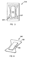
- the aperture 320 has a relatively large, rectangular opening 315 with a surrounding "bow-tie" portion 317 with holes 319 therein.
- the opening 315 provides a region with unrestricted permeability and the portion 317 with its holes 319 provides a region with intermediate permeability.
- a wad 342 that is produced with an aperture 320 as shown in Figure 3, is shown in Figure 4.
- the wad 342 has a substantially "bow-tie" external profile with a central rectangular portion 319 and a border 321.
- the central portion 319 is thicker than the border 321, as more air passes through that area of the strip 336 in alignment with the opening 315 than that in alignment with the portion 317, and therefore more fibres are collected in the middle than on the sides.
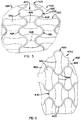
- the drum 312 can be made of any desired length, so that a number of wads can be formed side-by-side simultaneously.
- the apertures 320 need then naturally not be aligned with each other along the length of the drum wall 314, but can be staggered so that rows 420 (see Figures 5 and 6) of composite products, each comprising a layer of non-woven fabric and wads 342 of stabilized defiberized pulp particles located thereon as described, and a layer 422 of fluid-impervious material, eg a plastics film backing, laminated thereto, are produced.
- these rows can then be separated from one another by cutting along more-or-less sinusoidal, generally longitudinally extending, cut lines 424, into strips 426 of composite product.
- the strips 426 can then be cut along transversely extending cut lines 428 to produce individual composite products 430 comprising pads with side flaps.
- the individual composite products 430 are formed once the cuts along the cut lines 424 have been effected, so that the additional cuts along transverse cut lines are not required.
Abstract
Description
- THIS INVENTION relates to wads of particulate material. It relates in particular to a method of forming a wad of particulate material and to apparatus for forming such a wad. The invention extends to a wad formed by the method or apparatus.
- Absorbent pads for use in absorbing body fluids are well-known. Such pads include baby diapers, sanitary napkins, incontinence pads, wound dressings, breast pads for nursing mothers and the like. They are commonly made of absorbent cellulosic pulp fibres in the form of a batt or wad sandwiched between at least two layers of material. One layer is fluid-permeable and forms the layer adapted to face the wearer's body. The other layer conveniently is liquid-impervious and forms the side which faces away from the person's body and protects the person's clothing from soiling. This invention thus more specifically relates to a method and apparatus for forming a wad of particulate material suitable for use as a component of such an absorbent pad.
- According to the invention there is provided a method of forming a wad of particulate material, the wad having a predetermined shape, which includes
providing a permeable carrier which has first and second opposed surfaces;
providing a forming screen which also has first and second opposed surfaces and which is substantially impermeable except for a forming zone which has the said shape and which is permeable;
positioning the carrier and the screen adjacent one another with the second surface of the carrier adjacent the first surface of the screen;
generating a pressure differential across the carrier and the screen, there being a higher pressure at the first surface of the carrier such that a stream of fluid is caused to flow through the carrier substantially only in an area defined by the forming zone;
introducing the particulate material into the space adjacent the first surface of the carrier, which particulate material is carried by the fluid stream and is deposited on the first surface of the carrier; and
separating the carrier and the screen. - Further, according to the invention there is provided an apparatus for forming a wad of particulate material, the wad having a predetermined shape, which includes
a forming screen which has first and second opposed surfaces and which is substantially impermeable except for a forming zone which has the said shape and which is permeable;
a supply means for supplying a permeable carrier, which also has first and second opposed surfaces, with the second surface of the carrier adjacent the first surface of the screen;
a presssure differential generating means for generating, in use, a pressure differential across the carrier and the screen, there being a higher pressure at the first surface of the carrier, such that a stream of fluid is caused to flow through the carrier substantially only in an area defined by the forming zone;
introducing means for introducing the particulate material, in use, into the space adjacent the first surface of the carrier, such that the particulate material is carried by the fluid stream to be deposited on the first surface of the carrier; and
separating means for separating, in use, the carrier and the screen. - The apparatus may include the carrier.
- The forming zone may be an aperture in the screen, so that the whole forming zone has the same permeability. Instead, the forming zone may have a region of substantially high permeability and a region of intermediate permeability, with more particulate material being deposited on an area of the carrier in alignment with the high permeability region and less being deposited on an area in alignment with the intermediate permeability region. With such an embodiment, the forming zone may have an opening that is fairly large and which defines the region of high permeability with the region of low permeability being defined by a number of fairly small holes.
- The screen may have a plurality of forming zones that are spaced apart, and the carrier and the screen may be moved together through a pressurizing and introducing station where the fluid stream is caused to flow through the carrier only in those areas that are aligned with forming zones, thereby depositing the particulate material on the carrier and successively forming the wads thereon. The apparatus may thus have a suitable moving means for moving the carrier and screen. Preferably the carrier and the screen are moved continuously through the pressurizing and introducing station. It will be appreciated that a plurality of forming zones may be located together in the pressurizing and introducing station at the same time.
- The carrier is preferably a strip of non-woven fabric
- The particulate material may be fibrous and may be of a cellulosic material such as wood pulp, cotton, rayon or the like. Non-cellulosic materials may also be used such as polyolefinic or polyester fibres, etc.
- The screen may be endless and may comprise a cylindrical wall of a drum or a belt which is supported, in the pressurizing and introducing station, by a drum having a sieve-like cylindrical wall.
- Preferably, in the pressurizing and introducing station the carrier and screen are in contact with one another.
- The pressure differential generating means may comprise a vacuum generating means located adjacent the second surface of the screen.
- The apparatus may also include a shredder for shredding a sheet of fibrous material.
- The invention extends further to a wad of particulate material which has been formed using the method, or by apparatus, in accordance with the invention.
- Such a wad may be stabilised and bonded to the carrier and a liquid impervious backing may be laminated to the wad and the carrier, to provide a panty liner or the like. Instead, the wad and carrier can be applied over an absorbent layer, eg. a peatmoss layer, as a transition layer, with the absorbent layer being laminated to a liquid impervious backing to form a sanitary pad or the like. In the case where the wad is sandwiched directly between the carrier and the backing, it can be relatively thick, eg. it may have a basis weight of the order of about 120 grams/m², while, when it is used as a transitiion layer, it is envisaged that it will have a basis weight of about 35 grams/m².
- By means of the invention a simple method, and an apparatus that is easy to operate, are provided. The apparatus further has a simple forming station and, because the wad is not removed or transferred from one carrier to another after it is formed it is possible to produce the wads efficiently in multiple lanes.
- The invention is now described by way of example with reference to the accompanying diagrammatic drawings.
- In the drawings,
- FIGURE 1 shows a side view of apparatus according to one embodiment of the invention, for producing wads of particulate material;
- FIGURE 2 shows a side view of apparatus according to another embodiment of the invention, for producing wads of particulate material; and
- FIGURE 3 shows in greater detail a portion of a forming screen of the apparatus of Figures 1 and 2;
- FIGURE 4 shows a perspective view of a wad formed with a forming screen as shown in Figure 3; and
- FIGURES 5 and 6 show plan views of portions of carrier strips carrying a number of wads as produced by the apparatus of Figure 1 or Figure 2.
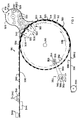
- Referring to Figure 1,
reference numeral 310 generally indicates apparatus according to one embodiment of the invention, for producing wads of particulate material. - The
apparatus 310 includes a circular cylindrical drum, generally indicated byreference numeral 312. Thedrum 312 has acylindrical wall 314. Thedrum 312 is adapted to be driven about arotational axis 316 by means of suitable drive means generally indicated byreference numeral 350. The drive means 350 comprises a plurality of radially inwardly protruding circumferentially spacedteeth 352 on thedrum 312. Two sets ofteeth 352, located respectively at the ends of thedrum 312, areprovided. Thedrum 312 is rotatably supported by two side plates (not shown) which have raised circular portions (also not shown) on their inner surfaces. The internal diameter of these portions is slightly larger than the outer diameter of the drum and are lined with a suitable non-slip material or with bearings. With each set ofteeth 352 is associated atoothed cog 354, with thecogs 354 being mounted on a single shaft oraxle 356. To one end of theshaft 356 is mounted apulley 358 which is aligned with apulley 360 mounted to theoutput shaft 362 of anelectric motor 366. Anendless belt 364 connects thepulleys - The
cylindrical wall 314 of thedrum 312 is generally imperforate, (ie. solid) with formingzones 320 in the form of apertures of predetermined shape, being provided therein. Theapertures 320 are described in more detail below with reference to Figure 3. - The
apparatus 310 also includes a vacuum generating means for applying a vacuum to the inside of thedrum wall 314, at a formingstation 322. The vacuum generating means includes avacuum box 308 with aduct 306 communicating with a vacuum source (not shown). Thebox 308 is located within thedrum 312, in contact with itswall 314. A pressure differential is formed across the drum wall with a higher pressure being present on the outside and a lower pressure on the inside. - The
apparatus 310 also includes a supply means, generally indicated byreference numeral 324, for supplying shredded defiberized pulp fibres to the outside of thedrum wall 314, at thestation 322. The supply means 324 comprises ahousing 326, apulp sheet inlet 328 leading into thehousing 326, arotatable shredder 330 located within the housing, drive means (not shown) for driving theshredder 330 to rotate it, and anair inlet 331 so that air can enter the housing. Thus, the required air flow inside the housing is generated by the movement of the shredder and the vacuum generating means. As theshredder 330 rotates, it shreds pulp sheet entering the inside of the housing via theinlet 328 intodefiberized pulp fibres 332 which are entrained in the air. - The
apparatus 310 still further includes a driven bobbin or roll 334 of non-woven fabric located such that astrip 336 of the nonwoven fabric can be fed therefrom directly onto the outside of thedrum wall 314, ahead of the supply means 324, as thedrum 312 rotates in the direction indicated byarrow 338. - The
apparatus 310 still further includes drawing off means (not shown) for drawing off thestrip 336 from thedrum wall 314 on the other side of the supply means 324. The drawing off means typically comprises a driven wind-up unit, and driven rollers for supporting thestrip 336, as required. - The
apparatus 310 also includes aspray nozzle 340 for applying a foamed acrylic binder towads 342 of shredded fibrous pulp formed on thestrip 336. A vacuum-generating means 344, generates a vacuum below thestrip 336 downstream of thenozzle 340 to spread the foamed binder through the wad and onto thestrip 336, Heating means, generally indicated byreference numeral 346, is located above thestrip 336, downstream of the vacuum generating means 344 for drying and chemically cross-linking the binder to stabilize thewads 342 and bond them to thestrip 336. Typically, the heating means 346 can be steam heated cans. When thewads 342 contain thermoplastic particles, thenozzle 340 and vacuum generating means 340 can be dispensed with, with thewads 342 then being stabilized and bonded directly by passing through or over the heating means 346. - In use, as the
drum 312 rotates in the direction ofarrow 338, acontinuous strip 336 of non-woven fabric is unwound directly from thebobbin 334 so that its surface 336.1 abuts against the outside surface of thedrum wall 314. At thestation 322, as a result of the vacuum generated by thebox 308 and theapertures 320, air passes through thestrip 336 only in those areas in alignment with theapertures 320. As thefibres 332 are entrained in the air, thefibres 332 are deposited on surface 336.2 of thestrip 336 in the said areas to form thewads 342, while no fibres are deposited elsewhere on that portion of thestrip 336 in the formingstation 322. Thestrip 336 with thewads 342 located thereon then pass to thenozzle 340 where thewads 342 are stabilized as hereinbefore described. - After composite products comprising the stabilized
wads 342 attached to thestrip 336, are formed, they can be laminated to a plastics film backing, eg a polythene film backing, whereafter the polythene film backing and the non-woven fabric can be cut to the same shape (but larger) as the wads. In this fashion soft panty-liners, and the like can be formed. Instead they can be laminated onto an absorbent layer, eg a peatmoss layer, as hereinbefore described, which can then in turn be laminated onto a polythene film backing layer, to form sanitary pads or the like. - Referring to Figure 2,
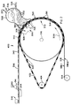
reference numeral 400 generally indicates apparatus according to another embodiment of the invention, for forming wads, - Parts of the
apparatus 400 which are the same or similar to theapparatus 310, are indicated with the same reference numerals. - The
apparatus 400 also has adrum 312 having a sieve-like, perforated circularcylindrical wall 314. Thedrum 312 of theapparatus 400 can be driven by the same drive means as thedrum 312 of theapparatus 310. However, theapertures 320 are not provided in the drum wall itself. Instead, theapparatus 400 includes a continuousimperforate belt 402 which passes around thedrum 312 as well as around a pulley, idler orroller 404. The position of the idler 404 can be adjusted, thereby to vary the tension in thebelt 402. Theapertures 320 are provided in thebelt 402. Thus, as thedrum 312 rotates, thebelt 402 continually engages a portion of the drum wall. After thestrip 336, with thewads 342 deposited thereon, has been drawn off, the belt disengages from thedrum wall 314, and passes around thepulley 404. - The Applicant believes that use of the
belt 402 can have advantages. For example, the desired shape of thewads 342 can be varied easily, by merely selecting abelt 402 havingapertures 320 of different shapes or sizes. Furthermore, the apparatus is not restricted to sizes and shapes ofapertures 320 being selected such that they fit exactly into thedrum wall 314. The Applicant further believes that drum blockages on extended runs can be avoided or reduced with theapparatus 400. - The
apertures 320 can be of any desired shape, depending on the end use. For example, they may be dogbone-shaped or butterfly-shaped if it is desired to provide panty-liners or sanitary pads respectively. - Referring to Figure 3, a portion of the wall 314 (or the belt 402) is shown. The
aperture 320 has a relatively large,rectangular opening 315 with a surrounding "bow-tie"portion 317 withholes 319 therein. Theopening 315 provides a region with unrestricted permeability and theportion 317 with itsholes 319 provides a region with intermediate permeability. - A
wad 342 that is produced with anaperture 320 as shown in Figure 3, is shown in Figure 4. Thus, thewad 342 has a substantially "bow-tie" external profile with a centralrectangular portion 319 and aborder 321. Thecentral portion 319 is thicker than theborder 321, as more air passes through that area of thestrip 336 in alignment with theopening 315 than that in alignment with theportion 317, and therefore more fibres are collected in the middle than on the sides. - It will be appreciated that with the
apparatus drum 312 can be made of any desired length, so that a number of wads can be formed side-by-side simultaneously. Theapertures 320 need then naturally not be aligned with each other along the length of thedrum wall 314, but can be staggered so that rows 420 (see Figures 5 and 6) of composite products, each comprising a layer of non-woven fabric andwads 342 of stabilized defiberized pulp particles located thereon as described, and alayer 422 of fluid-impervious material, eg a plastics film backing, laminated thereto, are produced. In a cutting station (not shown) these rows can then be separated from one another by cutting along more-or-less sinusoidal, generally longitudinally extending, cutlines 424, intostrips 426 of composite product. Thestrips 426 can then be cut along transversely extending cutlines 428 to produce individualcomposite products 430 comprising pads with side flaps. In the case of the arrangement as shown in Figure 6, the individualcomposite products 430 are formed once the cuts along thecut lines 424 have been effected, so that the additional cuts along transverse cut lines are not required.
Claims (29)
- A method of forming a wad (342) of particulate material (332), the wad having a predetermined shape, which includes
providing a permeable carrier (336) which has first (336.2) and second (336.1) opposed surfaces;
providing a forming screen (314,402) which also has first and second opposed surfaces and which is substantially impermeable except for a forming zone (320) which has the said shape and which is permeable;
positioning the carrier and the screen adjacent one another;
generating a pressure differential across the carrier and the screen, there being a higher pressure at the first surface of the carrier;
introducing the particulate material into the space adjacent the first surface of the carrier, which particulate material is carried by the fluid stream; and
separating the carrier and the screen, characterised thereby that the screen is located with its first surface adjacent the second surface of the carrier; and
the stream of fluid flows through the carrier substantially only in an area that is aligned with the forming zone of the screen such that the particulate material is deposited on the first surface of the carrier in the said area to form the wad. - The method claimed in Claim 1, characterised thereby that the forming zone is an aperture (320) in the screen.
- The method claimed in Claim 1, characterised thereby that the forming zone has a region of substantially high permeability (315) and a region of intermediate permeability (320), with more particulate material being deposited on an area of the carrier in alignment with the high permeability region and less being deposited on an area in alignment with the intermediate permeability region.
- The method claimed in Claim 1, characterised thereby that the screen has a plurality of forming zones that are spaced apart, and the carrier and the screen are moved together through a pressurizing and introducing station (322) where the fluid stream is caused to flow through the carrier only in those areas that are aligned with forming zones, thereby depositing the particulate material on the carrier and successively forming the wads thereon.
- The method claimed in Claim 4, characterised thereby that the carrier and the screen are moved continuously through the pressurizing and introducing station.
- The method claimed in Claim 4, characterised thereby that a plurality of forming zones are located together in the pressurizing and introducing station.
- The method claimed in Claim 4, characterised thereby that the screen is endless.
- The method claimed in Claim 1, characterised thereby that the carrier is a strip of non-woven fabric.
- The method claimed in Claim 1, characterised thereby that the particulate material is fibrous.
- The method claimed in Claim 7, characterised thereby that the screen comprises a cylindrical wall (314) of a drum.
- The method claimed in Claim 7, characterised thereby that the screen comprises a belt (402) which is supported, in the pressurizing and introducing station, by a drum (312) having a sieve-like cylindrical wall.
- The method claimed in Claim 1, characterised thereby that the carrier and the screen are in contact with one another.
- An apparatus (310, 400) for forming a wad (342) of particulate material (332), the wad having a predetermined shape, which includes
a forming screen (314, 402) which has first and second opposed surfaces and which is substantially impermeable except for a forming zone (320) which has the said shape and which is permeable;
a supply means (334) for supplying a permeable carrier, which also has first (336.2) and second (336.1) opposed surfaces;
a pressure differential generating means (308) for generating, in use, a pressure differential across the carrier and the screen, there being a higher pressure at the first surface of the carrier;
introducing means (324) for introducing the particulate material, in use, into the space adjacent the first surface of the carrier, such that the particulate material is carried by the fluid stream to be deposited on the first surface of the carrier; and
separating means for separating, in use, the carrier and the screen, characterised thereby that the screen is located, in use, with its first surface adjacent the second surface of the carrier such that, in use, the stream of fluid flows through the carrier substantially only in an area that is aligned with the forming zone of the screen and the particulate material is deposited on the first surface of the carrier in the said area to form the wad. - The apparatus claimed in Claim 13, characterised thereby that it includes the carrier.
- The apparatus claimed in Claim 13, characterised thereby that the screen has an aperture (320) which defines the forming zone.
- The apparatus claimed in Claim 13, characterised thereby that the forming zone has a region of substantially high permeability (315) and a region of intermediate permeability (320), such that, in use, more particulate material is deposited on an area of the carrier in alignment with the high permeability region and less is deposited on an area of the carrier in alignment with the intermediate permeability region.
- The apparatus claimed in Claim 13, characterised thereby that the screen has a plurality of forming zones that are spaced apart and the pressure differential generating means and the introducing means constitute a pressurizing and introducing station (322); and which includes a moving means (352, 354) for moving, in use, the carrier and the screen together through the said station, such that the fluid stream is caused to flow through the carrier only in those areas that are aligned with forming zones, thereby depositing the particulate material on the carrier and successively forming the wads thereon.
- The apparatus claimed in Claim 17, characterised thereby that the moving means moves the carrier and the screen continuously through the pressurizing and introducing station.
- The apparatus claimed in Claim 17, characterised thereby that a plurality of the forming zones are located together in the pressurizing and introducing station
- The apparatus claimed in Claim 17, characterised thereby that the screen is endless.
- The apparatus claimed in Claim 14, characterised thereby that the carrier is a roll of a non-woven fabric.
- The apparatus claimed in Claim 13, characterised thereby that the particulate material is fibrous.
- The apparatus claimed in Claim 20, characterised thereby that the screen comprises a cylindrical wall (314) of a drum.
- The apparatus claimed in Claim 20, characterised thereby that the screen comprises a belt (402), and which includes a support drum (312) having a sieve-like cylindrical wall for supporting the belt and the carrier at the pressurizing and introducing station.
- The apparatus claimed in Claim 13, characterised thereby that the supply means supplies the carrier, in use, in contact with the screen.
- The apparatus claimed in Claim 13, characterised thereby that the pressure differential generating means (308) comprises a vacuum generating means located adjacent the second surface of the screen.
- The apparatus claimed in Claim 22, characterised thereby that the introducing means includes a shredder (330) for shredding a sheet (328) of fibrous material.
- A wad of particulate material characterised thereby that it has been formed in accordance with the method claimed in Claim 1.
- A wad of particulate material characterised thereby that it has been formed by apparatus as claimed in Claim 13.
Applications Claiming Priority (2)
| Application Number | Priority Date | Filing Date | Title |
|---|---|---|---|
| ZA907272 | 1990-09-12 | ||
| ZA907272 | 1990-09-12 |
Publications (2)
| Publication Number | Publication Date |
|---|---|
| EP0478182A1 true EP0478182A1 (en) | 1992-04-01 |
| EP0478182B1 EP0478182B1 (en) | 1995-01-04 |
Family
ID=25580294
Family Applications (1)
| Application Number | Title | Priority Date | Filing Date |
|---|---|---|---|
| EP91308369A Expired - Lifetime EP0478182B1 (en) | 1990-09-12 | 1991-09-12 | A method and apparatus for forming a wad |
Country Status (8)
| Country | Link |
|---|---|
| EP (1) | EP0478182B1 (en) |
| AU (1) | AU650046B2 (en) |
| BR (1) | BR9103913A (en) |
| CA (1) | CA2051149C (en) |
| DE (1) | DE69106468T2 (en) |
| ES (1) | ES2066365T3 (en) |
| NZ (1) | NZ239726A (en) |
| ZA (2) | ZA917282B (en) |
Cited By (9)
| Publication number | Priority date | Publication date | Assignee | Title |
|---|---|---|---|---|
| WO1996017574A2 (en) * | 1994-12-07 | 1996-06-13 | Mcneil-Ppc, Inc. | Process for forming laminated absorbent structure |
| WO1997019659A1 (en) * | 1995-11-27 | 1997-06-05 | SCA Mölnlycke AB | Apparatus for air-laying fibre bodies on a moving air-permeable conveyor path |
| EP0958801A1 (en) * | 1998-05-12 | 1999-11-24 | Uni-Heartous Corporation | Production method of absorbent body |
| EP1048276A1 (en) | 1999-04-28 | 2000-11-02 | The Procter & Gamble Company | Method for applying a foamable movement obstruction agent to an absorbent member |
| EP0605015B2 (en) † | 1992-12-31 | 2002-05-15 | McNEIL-PPC, INC. | Method and system for making three-dimensional fabrics |
| US7906065B1 (en) | 2009-08-18 | 2011-03-15 | The Procter & Gamble Company | Method and apparatus for forming a batt of particulate material for use as a component in an absorbent core assembly |
| US7935299B2 (en) | 2005-08-17 | 2011-05-03 | The Procter & Gamble Company | Method and apparatus for forming a batt of particulate material for use as a component in an absorbent core assembly |
| EP3097895A1 (en) * | 2015-05-28 | 2016-11-30 | The Procter and Gamble Company | Method for forming unbonded fibrous structure |
| JP2019208874A (en) * | 2018-06-05 | 2019-12-12 | 花王株式会社 | Manufacturing method of absorber |
Families Citing this family (3)
| Publication number | Priority date | Publication date | Assignee | Title |
|---|---|---|---|---|
| US7682554B2 (en) | 2005-08-30 | 2010-03-23 | Kimberly-Clark Worldwide, Inc. | Method and apparatus to mechanically shape a composite structure |
| US7687012B2 (en) | 2005-08-30 | 2010-03-30 | Kimberly-Clark Worldwide, Inc. | Method and apparatus to shape a composite structure without contact |
| CN115105301A (en) * | 2022-05-24 | 2022-09-27 | 山东爸爸的选择健康科技有限公司 | Manufacturing method of absorption core body with fast diffusion and accumulation prevention |
Citations (3)
| Publication number | Priority date | Publication date | Assignee | Title |
|---|---|---|---|---|
| US3882216A (en) * | 1973-08-09 | 1975-05-06 | Int Paper Co | Disposable diaper |
| FR2521003A1 (en) * | 1982-02-05 | 1983-08-12 | Schickedanz Ver Papierwerk | PROCESS AND DEVICE FOR THE MANUFACTURE OF HYGIENIC LININGS FOR LADIES AND THUS OBTAINED LININGS |
| US4761258A (en) * | 1985-12-10 | 1988-08-02 | Kimberly-Clark Corporation | Controlled formation of light and heavy fluff zones |
Family Cites Families (1)
| Publication number | Priority date | Publication date | Assignee | Title |
|---|---|---|---|---|
| AU650902B2 (en) * | 1990-09-12 | 1994-07-07 | Mcneil-Ppc, Inc. | Process and apparatus for forming a composite product |
-
1991
- 1991-09-09 NZ NZ239726A patent/NZ239726A/en not_active IP Right Cessation
- 1991-09-11 CA CA002051149A patent/CA2051149C/en not_active Expired - Lifetime
- 1991-09-11 BR BR919103913A patent/BR9103913A/en not_active IP Right Cessation
- 1991-09-11 AU AU83838/91A patent/AU650046B2/en not_active Expired
- 1991-09-12 DE DE69106468T patent/DE69106468T2/en not_active Expired - Lifetime
- 1991-09-12 ZA ZA917282A patent/ZA917282B/en unknown
- 1991-09-12 ZA ZA917283A patent/ZA917283B/en unknown
- 1991-09-12 EP EP91308369A patent/EP0478182B1/en not_active Expired - Lifetime
- 1991-09-12 ES ES91308369T patent/ES2066365T3/en not_active Expired - Lifetime
Patent Citations (3)
| Publication number | Priority date | Publication date | Assignee | Title |
|---|---|---|---|---|
| US3882216A (en) * | 1973-08-09 | 1975-05-06 | Int Paper Co | Disposable diaper |
| FR2521003A1 (en) * | 1982-02-05 | 1983-08-12 | Schickedanz Ver Papierwerk | PROCESS AND DEVICE FOR THE MANUFACTURE OF HYGIENIC LININGS FOR LADIES AND THUS OBTAINED LININGS |
| US4761258A (en) * | 1985-12-10 | 1988-08-02 | Kimberly-Clark Corporation | Controlled formation of light and heavy fluff zones |
Cited By (15)
| Publication number | Priority date | Publication date | Assignee | Title |
|---|---|---|---|---|
| EP0605015B2 (en) † | 1992-12-31 | 2002-05-15 | McNEIL-PPC, INC. | Method and system for making three-dimensional fabrics |
| US5766388A (en) * | 1994-12-07 | 1998-06-16 | Mcneil-Ppc, Inc. | Process for forming laminated absorbent structures having reduced delamination tendencies |
| WO1996017574A2 (en) * | 1994-12-07 | 1996-06-13 | Mcneil-Ppc, Inc. | Process for forming laminated absorbent structure |
| WO1996017574A3 (en) * | 1994-12-07 | 1996-08-29 | Mcneil Ppc Inc | Process for forming laminated absorbent structure |
| WO1997019659A1 (en) * | 1995-11-27 | 1997-06-05 | SCA Mölnlycke AB | Apparatus for air-laying fibre bodies on a moving air-permeable conveyor path |
| EP0958801A1 (en) * | 1998-05-12 | 1999-11-24 | Uni-Heartous Corporation | Production method of absorbent body |
| EP1048276A1 (en) | 1999-04-28 | 2000-11-02 | The Procter & Gamble Company | Method for applying a foamable movement obstruction agent to an absorbent member |
| US7935299B2 (en) | 2005-08-17 | 2011-05-03 | The Procter & Gamble Company | Method and apparatus for forming a batt of particulate material for use as a component in an absorbent core assembly |
| US7906065B1 (en) | 2009-08-18 | 2011-03-15 | The Procter & Gamble Company | Method and apparatus for forming a batt of particulate material for use as a component in an absorbent core assembly |
| US8221672B2 (en) | 2009-08-18 | 2012-07-17 | The Procter & Gamble Company | Method and apparatus for forming a batt of particulate material for use as a component in an absorbent core assembly |
| US8616867B2 (en) | 2009-08-18 | 2013-12-31 | The Procter & Gamble Company | Method and apparatus for forming a batt of particulate material for use as a component in an absorbent core assembly |
| EP3097895A1 (en) * | 2015-05-28 | 2016-11-30 | The Procter and Gamble Company | Method for forming unbonded fibrous structure |
| WO2016191440A1 (en) * | 2015-05-28 | 2016-12-01 | The Procter & Gamble Company | Method for forming unbonded fibrous structures |
| JP2019208874A (en) * | 2018-06-05 | 2019-12-12 | 花王株式会社 | Manufacturing method of absorber |
| JP7118752B2 (en) | 2018-06-05 | 2022-08-16 | 花王株式会社 | Absorbent manufacturing method |
Also Published As
| Publication number | Publication date |
|---|---|
| AU8383891A (en) | 1992-03-19 |
| BR9103913A (en) | 1992-05-26 |
| ZA917282B (en) | 1993-03-12 |
| NZ239726A (en) | 1994-05-26 |
| AU650046B2 (en) | 1994-06-09 |
| CA2051149C (en) | 2002-02-26 |
| ES2066365T3 (en) | 1995-03-01 |
| EP0478182B1 (en) | 1995-01-04 |
| ZA917283B (en) | 1993-03-12 |
| DE69106468D1 (en) | 1995-02-16 |
| CA2051149A1 (en) | 1992-03-13 |
| DE69106468T2 (en) | 1995-06-14 |
Similar Documents
| Publication | Publication Date | Title |
|---|---|---|
| US8178747B2 (en) | Absorbent core with elongate liquid holding formation | |
| US7094373B2 (en) | Process and apparatus for air forming an article having a plurality of reinforced superimposed fibrous layers | |
| EP0394274B9 (en) | Absorbent pad | |
| US4016628A (en) | Method and apparatus for forming absorbent articles | |
| US7568900B2 (en) | Apparatus for making a reinforced fibrous absorbent member | |
| EP0605015B1 (en) | Method and system for making three-dimensional fabrics | |
| EP0159630A2 (en) | Selective layering of superabsorbents in meltblown substrates | |
| EP0478182B1 (en) | A method and apparatus for forming a wad | |
| EP0479442B1 (en) | Process and apparatus for forming a composite product | |
| KR100988697B1 (en) | Controlled placement of a reinforcing web within a fibrous absorbent | |
| RU2666104C1 (en) | Method of manufacture of absorbing structures with jumpers | |
| AU650902B2 (en) | Process and apparatus for forming a composite product | |
| WO2011111397A1 (en) | Laminated product treating apparatus | |
| JP6255232B2 (en) | Absorber manufacturing equipment | |
| WO2004028426A1 (en) | Process and apparatus for air forming an article having a plurality of reinforced superimposed fibrous layers |
Legal Events
| Date | Code | Title | Description |
|---|---|---|---|
| PUAI | Public reference made under article 153(3) epc to a published international application that has entered the european phase |
Free format text: ORIGINAL CODE: 0009012 |
|
| AK | Designated contracting states |
Kind code of ref document: A1 Designated state(s): DE ES FR |
|
| 17P | Request for examination filed |
Effective date: 19920908 |
|
| 17Q | First examination report despatched |
Effective date: 19940318 |
|
| GRAA | (expected) grant |
Free format text: ORIGINAL CODE: 0009210 |
|
| AK | Designated contracting states |
Kind code of ref document: B1 Designated state(s): DE ES FR |
|
| REF | Corresponds to: |
Ref document number: 69106468 Country of ref document: DE Date of ref document: 19950216 |
|
| REG | Reference to a national code |
Ref country code: ES Ref legal event code: FG2A Ref document number: 2066365 Country of ref document: ES Kind code of ref document: T3 |
|
| ET | Fr: translation filed | ||
| PLBI | Opposition filed |
Free format text: ORIGINAL CODE: 0009260 |
|
| PLAB | Opposition data, opponent's data or that of the opponent's representative modified |
Free format text: ORIGINAL CODE: 0009299OPPO |
|
| 26 | Opposition filed |
Opponent name: THE PROCTER & GAMBLE COMPANY Effective date: 19951004 |
|
| R26 | Opposition filed (corrected) |
Opponent name: THE PROCTER & GAMBLE COMPANY Effective date: 19951004 |
|
| PLBF | Reply of patent proprietor to notice(s) of opposition |
Free format text: ORIGINAL CODE: EPIDOS OBSO |
|
| PLBF | Reply of patent proprietor to notice(s) of opposition |
Free format text: ORIGINAL CODE: EPIDOS OBSO |
|
| PLBO | Opposition rejected |
Free format text: ORIGINAL CODE: EPIDOS REJO |
|
| APAC | Appeal dossier modified |
Free format text: ORIGINAL CODE: EPIDOS NOAPO |
|
| APAE | Appeal reference modified |
Free format text: ORIGINAL CODE: EPIDOS REFNO |
|
| APAC | Appeal dossier modified |
Free format text: ORIGINAL CODE: EPIDOS NOAPO |
|
| PLBQ | Unpublished change to opponent data |
Free format text: ORIGINAL CODE: EPIDOS OPPO |
|
| PLAB | Opposition data, opponent's data or that of the opponent's representative modified |
Free format text: ORIGINAL CODE: 0009299OPPO |
|
| R26 | Opposition filed (corrected) |
Opponent name: THE PROCTER & GAMBLE COMPANY Effective date: 19951004 |
|
| APAC | Appeal dossier modified |
Free format text: ORIGINAL CODE: EPIDOS NOAPO |
|
| PLBN | Opposition rejected |
Free format text: ORIGINAL CODE: 0009273 |
|
| STAA | Information on the status of an ep patent application or granted ep patent |
Free format text: STATUS: OPPOSITION REJECTED |
|
| 27O | Opposition rejected |
Effective date: 19980707 |
|
| APAH | Appeal reference modified |
Free format text: ORIGINAL CODE: EPIDOSCREFNO |
|
| PGFP | Annual fee paid to national office [announced via postgrant information from national office to epo] |
Ref country code: FR Payment date: 20100921 Year of fee payment: 20 |
|
| PGFP | Annual fee paid to national office [announced via postgrant information from national office to epo] |
Ref country code: DE Payment date: 20100908 Year of fee payment: 20 |
|
| PGFP | Annual fee paid to national office [announced via postgrant information from national office to epo] |
Ref country code: ES Payment date: 20101018 Year of fee payment: 20 |
|
| REG | Reference to a national code |
Ref country code: DE Ref legal event code: R071 Ref document number: 69106468 Country of ref document: DE |
|
| REG | Reference to a national code |
Ref country code: DE Ref legal event code: R071 Ref document number: 69106468 Country of ref document: DE |
|
| PG25 | Lapsed in a contracting state [announced via postgrant information from national office to epo] |
Ref country code: DE Free format text: LAPSE BECAUSE OF EXPIRATION OF PROTECTION Effective date: 20110913 |
|
| REG | Reference to a national code |
Ref country code: ES Ref legal event code: FD2A Effective date: 20130725 |
|
| PG25 | Lapsed in a contracting state [announced via postgrant information from national office to epo] |
Ref country code: ES Free format text: LAPSE BECAUSE OF EXPIRATION OF PROTECTION Effective date: 20110913 |