EP0479033A2 - Method for the determination of the concentration of electrochemically convertible gases - Google Patents
Method for the determination of the concentration of electrochemically convertible gases Download PDFInfo
- Publication number
- EP0479033A2 EP0479033A2 EP91115750A EP91115750A EP0479033A2 EP 0479033 A2 EP0479033 A2 EP 0479033A2 EP 91115750 A EP91115750 A EP 91115750A EP 91115750 A EP91115750 A EP 91115750A EP 0479033 A2 EP0479033 A2 EP 0479033A2
- Authority
- EP
- European Patent Office
- Prior art keywords
- potential
- analyte
- electrode
- concentration
- measurement
- Prior art date
- Legal status (The legal status is an assumption and is not a legal conclusion. Google has not performed a legal analysis and makes no representation as to the accuracy of the status listed.)
- Withdrawn
Links
Images


Classifications
-
- G—PHYSICS
- G01—MEASURING; TESTING
- G01N—INVESTIGATING OR ANALYSING MATERIALS BY DETERMINING THEIR CHEMICAL OR PHYSICAL PROPERTIES
- G01N27/00—Investigating or analysing materials by the use of electric, electrochemical, or magnetic means
- G01N27/26—Investigating or analysing materials by the use of electric, electrochemical, or magnetic means by investigating electrochemical variables; by using electrolysis or electrophoresis
- G01N27/416—Systems
- G01N27/42—Measuring deposition or liberation of materials from an electrolyte; Coulometry, i.e. measuring coulomb-equivalent of material in an electrolyte
-
- G—PHYSICS
- G01—MEASURING; TESTING
- G01N—INVESTIGATING OR ANALYSING MATERIALS BY DETERMINING THEIR CHEMICAL OR PHYSICAL PROPERTIES
- G01N27/00—Investigating or analysing materials by the use of electric, electrochemical, or magnetic means
- G01N27/26—Investigating or analysing materials by the use of electric, electrochemical, or magnetic means by investigating electrochemical variables; by using electrolysis or electrophoresis
- G01N27/416—Systems
- G01N27/48—Systems using polarography, i.e. measuring changes in current under a slowly-varying voltage
Definitions
- the invention is based on a method for determining the concentration of electrochemically convertible gases according to the preamble of claim 1.
- Polarographic or comparable gas sensors are based on a current measurement between an electrode configuration consisting of two or three electrodes, the current amplitude being a measure of is the partial pressure of the sample gas.
- the current amplitude being a measure of is the partial pressure of the sample gas.
- amperometric gas detection cells It is also common to operate amperometric gas detection cells with a fixed potential, and the current resulting under these circumstances can be limited to membrane diffusion. It then depends linearly on the concentration of the electroactive analyte, which is converted at a specific working potential (sensor of the so-called "type 1"). However, since each species is now converted, provided that it is electroactive at the applied working potential, such known amperometric gas detection cells usually only result in a relatively low selectivity, even if the aim is to operate the corresponding electrochemical sensors only at such potentials which at least a larger number of other existing substances does not react electroactive.
- Another way of dealing with the problem of low selectivity is to arrange different sensors with different selectivities by choosing work potential and / or electrode material, for example in the form of a whole row of sensors, and to use appropriate techniques to differentiate the respective substances (type 2 sensor ).
- the analyte is preferably adsorbed, while there are high overpotentials for species or gases that also react in this area.
- electrolytic effects can best be exploited by using the voltammetric techniques mentioned, by first working with a fixed potential and a controlled adsorption resulting therefrom and then applying a ramp-shaped voltage rise to the working electrode. This process is referred to below as the so-called LPSV process and is derived from the English term "linear potential sweep voltammetry".
- the LPSV method is based on the fact that the working electrode is initially operated with a fixed potential (E2; for example zero potential), during a predetermined adsorption time t ads , so as to adsorb the analyte under thermodynamically and diffusion- controlled conditions.
- E2 a fixed potential
- the adsorbed species is then electrochemically converted in a linear voltage increase at the working electrode that follows the adsorption time.
- the object of the present invention is to remedy this and to provide a possibility for the correct determination of a background or zero signal value, in which any change in the measuring environment becomes superfluous and, above all, on all other necessary mechanical aids such as valves, sensor exchange or the like . can be dispensed with.
- the invention solves this problem with the characterizing features of claim 1 and has the advantage that another potential sequence can be carried out easily and immediately following a measuring cycle or a measuring sequence, which gives the desired zero signal with high accuracy, without mechanical on the measuring apparatus at all something needs to be changed and without first of all removing the analyte from the measuring environment.
- the invention is based on the knowledge that sufficiently short adsorption times can be set, during which only so little analyte can adsorb that the amount of charge correlated therewith is negligible.
- the invention makes use of this knowledge and therefore proposes to initiate a new potential sweep immediately after the measurement cycle (adsorption potential during t ads with subsequent potential sweep ), which can be assigned to a reference sequence and whose current response is necessarily as if the analyte was not at all is present in the solution or in the gas mixture to be examined, precisely because it did not have time to attach or adsorb on the working electrode.
- an activity determination of the sensor surface is possible by comparing the resulting current curve profiles, also as a sum signal, if several test gases to be investigated are involved, over time, by comparing the initial peak heights or peak areas (characteristic double peak formation; PtH), which The beginning of the potential sweep occurs, is evaluated accordingly and observed over time. From this, an indication of the long-term stability of the sensor can be determined, with the course of the reference cycle preferably being selected, since in this case the sensor surface is occupied by hydrogen, resulting from the aqueous environment, and these hydrogen peaks are higher the more active the sensor surface ( still).
- an electrochemical cell 10 thermostatically controlled to a predetermined temperature contains a working electrode 11, a reference electrode 12, further electrodes 13a, 13b for pre-electrolysis, and a gas inlet line 14, which are not of particular interest here.
- the construction of the electrochemical cell can yourself through complete a stirring rod 15 driven from the outside, for example by electromagnetic coupling.
- the working electrode comprises a polished polycrystalline platinum sheet 11b on which the adsorption and conversion processes take place;
- the reference electrode 12 can be a conventional standard hydrogen electrode or another conventional reference system, it being possible for both the platinum surface and the reference electrode to be separated from the cell electrolyte via diaphragms. All the potentials specified below refer to the reference signal supplied by the reference electrode.
- a voltage curve and current evaluation circuit 15 which is electrically connected to the connections of the working electrode and the reference electrode, is supplied by a function generator 16 for carrying out the LPSV method, a potential profile which is given as an example in the circuit located under the function generator 16;
- An evaluation circuit 17 evaluating the data supplied by the voltage control circuit 15 then detects at least the two voltage profiles of the measurement and reference sequence in the area of the current response and derives an indication of the concentration of the analyte to be examined from these two signals.
- E 1 1400 mV
- This specifically specified adsorption (specified by the duration of the adsorption time t ads , as a result of which a specific selectivity behavior on different species can also be realized) is then followed by the linear potential sweep in accordance with the curve profile A, i.e. a comparatively steep ramp-shaped potential increase at the working electrode up to one
- Final potential E3 here again numerical values, but not limiting the scope of the invention, are given with E3, for example 1600 mV.
- the sweep rate ie the time for the ramp-shaped voltage rise, is, for example, 1000 mV / s; the sweep rates must be so fast that the diffusion of species in the solution to the electrode can be neglected. Under these circumstances, for example, a 2 eV sweep has ended before further species can diffuse through the Nernst layer.
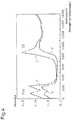
- Such a forced voltage curve on the working electrode in accordance with a measurement sequence leads to a current curve curve as shown in Fig. 4 at I, i.e. initially there are two lower peaks, which are around 80 and 220 mV, with a subsequent reaction peak, depending on the concentration of the analytes (CO), at around 880 mV.
- the initial peaks in the course of the current are due to a residual occupation of the adsorption sites not occupied by the analyte with hydrogen; they are increasingly weakened in proportion to the concentration of the sample gas; accordingly, depending on the concentration, the subsequent peak shape (at 880 mV) is the higher and more pronounced, the stronger the concentration of the analyte in the measuring medium - in FIG.
- maintaining the upper constant potential E3 for a predetermined period of time, for example t3 ⁇ 2 seconds, can follow the ramp-shaped voltage rise.
- the current curve profile I does not give an absolute value for the concentration of the analyte, since the integration of the current surfaces must necessarily be related to the background, that is to say to a zero signal profile.
- the measuring sequence is followed by a reference sequence, which in its general voltage course may be identical to the measurement sequence, with the exception that an adsorption time t ads in which the species present can adsorb markedly is not permitted; this is so small or disappears completely that any adsorption of both the analyte and other interfering species in the measurement environment is excluded. Therefore, in a typical embodiment, the time period in which the working electrode remains at the lower constant potential of E2 can be less than or equal to 1 sec. (T2 ⁇ 1 s).
- the analyte concentration is then reached by subtracting the current curves of the measurement and reference sweep from one another and then integrating the resulting difference curve in the area where the analyte is converted.
- curve profiles shown relate specifically to CO adsorption as analytes, where such curves also apply qualitatively to other gases of interest that can be converted electrochemically, the peaks of which then only occur at other potential values.
- reaction potential can be expected in the range from 800 to 1100 mV.
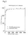
- FIG. 3 shows the time dependence of the CO adsorption (charge via t ads ). 3 therefore shows typical results for different adsorption times for a better understanding of the adsorption kinetics. It should be added that the adsorption rate is strongly influenced by geometric influences and stirring processes in the vessel and of course is also dependent on the free enthalpy of adsorption.
- Another essential aspect of the present invention is that an estimation of the electrode quality is possible by observing the current curves shown in FIG. 4, so that a possible decrease in the electrode sensitivity over time is detected and introduced as a correction parameter for the sensor sensitivity or used as a measure can be when a replacement of the electrode makes sense.
- the initial peaks in the current curve which can be attributed to hydrogen conversion, are a good measure of the electrode aging, since a high electrode surface activity is combined with correspondingly high peaks, as they occur in particular when determining the background.
Abstract
Description
Die Erfindung geht aus von einem Verfahren zur Konzentrationsbestimmung von elektrochemisch umsetzbaren Gasen nach dem Oberbegriff des Anspruchs 1.The invention is based on a method for determining the concentration of electrochemically convertible gases according to the preamble of
Bekannt ist ein solches Verfahren aus den US-Patentschriften 4 508 598 bzw. 4 729 824. Vorauszuschicken ist in diesem Zusammenhang, daß übliche gegenwärtig verwendete elektrochemische Gassensoren entweder vom potentiometrischen oder vom polarographischen Typ sind.Such a method is known from US Pat. Nos. 4,508,598 and 4,729,824. In this connection, it should be noted that conventional electrochemical gas sensors currently used are either of the potentiometric or of the polarographic type.
Polarographische oder mit diesem vergleichbare Gassensoren basieren auf einer Strommessung zwischen einer aus zwei oder drei Elektroden bestehenden Elektrodenkonfiguration, wobei die Stromamplitude ein Maß für den Partialdruck des Meßgases ist. Bei diesen Sensoren ergeben sich in Verbindung mit geringer Selektivität als weitere Nachteile eine ebenfalls nur geringe Empfindlichkeit sowie zum Teil erhebliche Drifterscheinungen.Polarographic or comparable gas sensors are based on a current measurement between an electrode configuration consisting of two or three electrodes, the current amplitude being a measure of is the partial pressure of the sample gas. With these sensors, in conjunction with low selectivity, there are further disadvantages as well as low sensitivity and, in some cases, significant drift phenomena.
Es ist ferner üblich, amperometrische Gasdetektionszellen mit einem festen Potential zu betreiben, wobei der unter diesen Umständen resultierende Strom auf die Membrandiffusion begrenzt werden kann. Er hängt dann linear von der Konzentration des elektroaktiven Analyten ab, der bei einem jeweils spezifischen Arbeitspotential umgewandelt wird (Sensor vom sogenannten "Typ 1"). Da nun aber jede Spezies umgewandelt wird, vorausgesetzt, sie ist bei dem angelegten Arbeitspotential elektroaktiv, ergibt sich bei solchen bekannten amperometrischen Gasdetektionszellen üblicherweise nur eine relativ niedrige Selektivität, auch wenn man darauf abstellt, die entsprechenden elektrochemischen Sensoren nur bei solchen Potentialen zu betreiben, bei denen wenigstens eine größere Anzahl anderer vorhandener Substanzen nicht elektroaktiv reagiert.It is also common to operate amperometric gas detection cells with a fixed potential, and the current resulting under these circumstances can be limited to membrane diffusion. It then depends linearly on the concentration of the electroactive analyte, which is converted at a specific working potential (sensor of the so-called "
Eine weitere Möglichkeit, dem Problem der niedrigen Selektivität zu begegnen, besteht darin, daß man verschiedene Sensoren mit unterschiedlichen Selektivitäten durch Wahl von Arbeitspotential und/oder Elektrodenmaterial etwa in Form einer ganzen Sensorreihe anordnet und entsprechende Techniken zur Unterscheidung der jeweiligen Substanzen anwendet (Typ 2 Sensor).Another way of dealing with the problem of low selectivity is to arrange different sensors with different selectivities by choosing work potential and / or electrode material, for example in the form of a whole row of sensors, and to use appropriate techniques to differentiate the respective substances (type 2 sensor ).
Hier setzt nun der aus den beiden weiter vorn genannten US-Patenten 4 508 598 oder 4 429 824 gemachte Vorschlag ein, der darin besteht, daß man bei Vorhandensein nur eines Sensors die Selektivität durch sogenannte voltammetrische Techniken erhöht. Hierdurch gelingt die Trennung der Spezies, die üblicherweise bei einem Festpotential umgewandelt werden, durch deren aufeinanderfolgende Umwandlung im Verlauf eines rampenförmigen Spannungsanstiegs (potential sweep). Diese Konzeption macht allerdings Spezien mit Umwandlungspotentialen erforderlich, die zur einwandfreien Auflösung energetisch einen hinreichenden Abstand aufweisen müssen.This is where the suggestion made from the two US Patents 4,508,598 or 4,429,824 mentioned above begins, which consists in the fact that, when present only one sensor increases the selectivity using so-called voltammetric techniques. This enables the separation of the species, which are usually converted at a fixed potential, by their successive conversion in the course of a ramp-shaped voltage rise (potential sweep). However, this conception requires species with conversion potentials that have to be at a sufficient distance energetically for a perfect resolution.
Eine weitere Möglichkeit zur Selektivitätserhöhung beruht auf der Ausnutzung elektrokatalytischer Effekte und spezifischer Adsorptionseigenschaften. Indem man hier geeignete Elektrodenmaterialien auswählt, wird bevorzugt der Analyt adsorbiert, während sich für in diesem Bereich ebenfalls reagierende Spezien oder Gase hohe Überpotentiale ergeben. Diese elektrolytischen Effekte lassen sich am besten durch Anwendung der erwähnten voltammetrischen Techniken ausnutzen, indem man zunächst mit einem Festpotential und einer aus diesen herrührenden kontrollierten Adsorption arbeitet und anschließend die Arbeitselektrode mit einem rampenförmigen Spannungsanstieg beaufschlagt. Dieses Verfahren wird im folgenden als sogenanntes LPSV-Verfahren bezeichnet und leitet sich aus der englischen Bezeichnung "linear potential sweep voltammetry" ab.Another possibility for increasing the selectivity is based on the use of electrocatalytic effects and specific adsorption properties. By selecting suitable electrode materials here, the analyte is preferably adsorbed, while there are high overpotentials for species or gases that also react in this area. These electrolytic effects can best be exploited by using the voltammetric techniques mentioned, by first working with a fixed potential and a controlled adsorption resulting therefrom and then applying a ramp-shaped voltage rise to the working electrode. This process is referred to below as the so-called LPSV process and is derived from the English term "linear potential sweep voltammetry".
Zusammengefaßt beruht also das LPSV-Verfahren darauf, daß man die Arbeitselektrode zunächst mit einem Festpotential (E₂; beispielsweise Null-Potential) betreibt, während einer vorgegebenen Adsorptionszeit tads, um so den Analyten unter thermodynamisch und diffusionskontrollierten Bedingungen zu adsorbieren.In summary, the LPSV method is based on the fact that the working electrode is initially operated with a fixed potential (E₂; for example zero potential), during a predetermined adsorption time t ads , so as to adsorb the analyte under thermodynamically and diffusion- controlled conditions.
Durch Veränderung der Adsorptionszeit tads kann man schon an dieser Stelle eine gewisse Selektivität einführen aufgrund des unterschiedlichen Adsorptionsverhaltens verschiedener Gase. In einem zweiten, die Selektivität entscheidend beeinflussenden Schritt wird dann in einem sich an die Adsorptionszeit anschließenden linearen Spannungsanstieg an der Arbeitselektrode die adsorbierte Spezies elektrochemisch umgewandelt.By changing the adsorption time t ads , a certain selectivity can be introduced at this point due to the different adsorption behavior of different gases. In a second step, which decisively influences the selectivity, the adsorbed species is then electrochemically converted in a linear voltage increase at the working electrode that follows the adsorption time.
Dies führt zu von den Konzentration des Meßgases und seiner Art abhängigen Stromantworten, so daß sich ein Stromverlauf über der Zeit und bezogen auf den rampenförmigen Potentialanstieg der Arbeitselektrode ergibt, wie er beispielsweise in Fig. 14 des US-Patents 4 729 824 oder auch Fig. 18 des US-Patents 4 508 598 jedenfalls qualitativ dargestelllt ist. Man kann dann durch Integration der sich während des Potentialsweeps ergebenden Peakflächen des Stroms über den Spannungsverlauf auf die Konzentration des Analyten rückschließen, vorausgesetzt, man führt eine stets notwendige Untergrundsubtraktion noch aus, um die ermittelten Strompeakflächen auf den Stromkurvenverlauf zu beziehen, der sich dann ergibt, wenn der Analyt im untersuchten Fluid (Gas oder Flüssigkeit) nicht vorhanden ist. Für die Messung von CO, auf die sich das US-Patent 4 508 598 hauptsächlich bezieht, wird in dieser Veröffentlichung auch ausdrücklich darauf hingewiesen (Spalte 6, Zeilen 48/50), daß die Subtraktion der Untergrundladung bei fehlendem Analyten für die Integration der ermittelten Ladung und der daraus resultierenden Konzentrationsableitung notwendig ist. Dies bedeutet, daß in nicht selten problematischer Weise, soweit dies überhaupt möglich ist, der Untergrund dadurch aufgenommen werden muß, daß durch Betätigung entsprechender Ventile der Analyt aus dem Meßfluid ausgeschlossen oder entfernt wird, oder der Sensor selbst in ein anderes Gefäß umgesetzt werden muß, in welchem der Analyt nicht vorhanden ist.This leads to current responses which are dependent on the concentration of the measurement gas and its type, so that there is a current profile over time and in relation to the ramp-shaped potential increase of the working electrode, as is shown, for example, in FIG. 14 of US Pat. No. 4,729,824 or also FIG. 18 of U.S. Patent 4,508,598 is qualitatively shown. The integration of the peak areas of the current resulting during the potential sweep can then be used to draw conclusions about the concentration of the analyte via the voltage profile, provided that the subtraction is always necessary to relate the current peak areas to the current curve profile, which then results, if the analyte is not present in the fluid (gas or liquid) under investigation. For the measurement of CO, to which US Pat. No. 4,508,598 mainly relates, this publication also expressly points out (column 6, lines 48/50) that subtraction of the background charge in the absence of analyte for the integration of the ascertained Charge and the resulting concentration derivation is necessary. This means that it is often problematic, if at all it is possible that the background must be taken up in that the analyte is excluded or removed from the measuring fluid by actuating appropriate valves, or the sensor itself has to be converted into another vessel in which the analyte is not present.
Dementsprechend liegt der vorliegenden Erfindung die Aufgabe zugrunde, hier Abhilfe zu schaffen und eine Möglichkeit zur einwandfreien Bestimmung eines Untergrund- oder Nullsignalwertes anzugeben, bei der jeglicher Wechsel des Meßmilieus überflüssig wird und vor allem auf alle sonst notwendigen mechanischen Hilfsmittel wie Ventile, Sensoraustausch o.dgl. verzichtet werden kann.Accordingly, the object of the present invention is to remedy this and to provide a possibility for the correct determination of a background or zero signal value, in which any change in the measuring environment becomes superfluous and, above all, on all other necessary mechanical aids such as valves, sensor exchange or the like . can be dispensed with.
Die Erfindung löst diese Aufgabe mit den kennzeichnenden Merkmalen des Anspruchs 1 und hat den Vorteil, daß problemlos und unmittelbar einem Meßzyklus oder einer Meßsequenz folgend eine weitere Potentialsequenz durchgeführt werden kann, die mit hoher Genauigkeit das gewünschte Nullsignal ergibt, ohne daß mechanisch an der Meßapparatur überhaupt etwas geändert zu werden braucht und ohne daß vor allen Dingen der Analyt aus dem Meßmilieu entfernt zu werden braucht.The invention solves this problem with the characterizing features of
Die Erfindung beruht nämlich auf der Erkenntnis, daß genügend kurze Adsorptionszeiten eingestellt werden können, während denen nur so wenig Analyt adsorbieren kann, daß die damit korrelierte Ladungsmenge vernachlässigbar ist.The invention is based on the knowledge that sufficiently short adsorption times can be set, during which only so little analyte can adsorb that the amount of charge correlated therewith is negligible.
Die Erfindung macht sich diese Erkenntnis zunutze und schlägt daher vor, unmittelbar nach dem Meßzyklus (Adsorptionspotential während tads mit anschließendem Potentialsweep) folgend einen erneuten Potentialsweep einzuleiten, der einer Referenzsequenz zugeordnet werden kann und dessen Stromantwort notwendigerweise so ausfällt, als wenn der Analyt gar nicht in der Lösung oder in dem zu untersuchenden Gasgemisch vorhanden ist, eben deshalb, weil er keine Zeit hatte, sich an der Arbeitselektrode anzulagern bzw. zu adsorbieren.The invention makes use of this knowledge and therefore proposes to initiate a new potential sweep immediately after the measurement cycle (adsorption potential during t ads with subsequent potential sweep ), which can be assigned to a reference sequence and whose current response is necessarily as if the analyte was not at all is present in the solution or in the gas mixture to be examined, precisely because it did not have time to attach or adsorb on the working electrode.
Untersuchungen haben ergeben, daß es hierdurch gelingt, einen Nullsignal-Kurvenverlauf zu ermitteln, der mit hoher Genauigkeit einem Kurvenverlauf des gleichen Sensors entspricht, wenn der Analyt tatsächlich nicht vorhanden ist, so daß es durch rein elektrochemische/elektronische Mittel, nämlich Einteilung des Meßvorgangs in eine Meßsequenz und eine sich daran anschliessende Referenzsequenz, möglich ist, sowohl die durch das Adsorptionsverhalten des Analyten belastete und daher konzentrationsabhängige Stromantwort als auch das Untergrundsignal zu gewinnen, so daß es durch Subtraktionsbildung der beiden Kurvenverläufe und anschließende Integration möglich ist, mit hoher Genauigkeit und praktisch in einem Meßvorgang die Konzentration des gewünschten Analyten herauszurechnen.Investigations have shown that it is possible to determine a zero-signal curve which corresponds to a curve of the same sensor with high accuracy if the analyte is actually not present, so that it can be divided into purely electrochemical / electronic means, namely division of the measurement process into a measurement sequence and a subsequent reference sequence, it is possible to obtain both the current response, which is burdened by the adsorption behavior of the analyte and therefore concentration-dependent, and the background signal, so that it is possible by subtraction of the two curves and subsequent integration, with high accuracy and practicality calculate the concentration of the desired analyte in one measurement process.
Durch die in den Unteransprüchen aufgeführten Maßnahmen sind vorteilhafte Weiterbildungen und Verbesserungen der Erfindung möglich. Besonders vorteilhaft ist die zur Verfügungstellung einer sehr geringen Zeitdauer tads (beispielsweise in numerischen, jedoch die Erfindung nicht beschränkenden Werten ausgedrückt von 1 Sekunde) in der sich an die Meßsequenz anschließenden Referenzsequenz bei Konstantpotential(E₂, wobei E₂ beispielsweise 0 mV sein kann), um störende kapazitive Entladungsphänomene an der Elektrode auszuschalten. Die im Vergleich zu üblichen Adsorptionszeiten extrem geringe Wartezeit bis zum Beginn des Referenzsweeps eliminiert diesen "Kapazitäts"-Einfluß der Elektrode, da ein entsprechendes, hierauf zurückzuführendes Potential mit einer e-Funktion innerhalb weniger Sekundenbruchteile abfällt.Advantageous further developments and improvements of the invention are possible through the measures listed in the subclaims. The provision of a very short time period t ads (for example in numerical, however, is particularly advantageous the invention non-limiting values expressed by 1 second) in the reference sequence following the measuring sequence at constant potential (E₂, where E₂ may be 0 mV, for example) in order to switch off interfering capacitive discharge phenomena at the electrode. The extremely short waiting time until the start of the reference sweep, in comparison to conventional adsorption times, eliminates this "capacity" influence of the electrode, since a corresponding potential due to this drops with an e-function within fractions of a second.
Vorteilhaft ist ferner, daß eine Aktivitätsbestimmung der Sensoroberfläche möglich ist durch Vergleich der sich ergebenden Stromkurvenverläufe, auch als Summensignal, wenn mehrere zu untersuchende Meßgase beteiligt sind, über der Zeit, indem man die anfänglichen Peakhöhen oder Peakflächen (charakteristische Doppelpeakbildung; PtH), die bei Beginn des Potentialsweeps auftreten, entsprechend auswertet und über der Zeit beobachtet. Hieraus läßt sich eine Angabe über die Langzeitstabilität des Sensors ermitteln, wobei bevorzugt der Verlauf des Referenzzyklus gewählt wird, da sich in diesem Fall eine Sensoroberflächenbelegung durch Wasserstoff, herrührend aus dem wässrigen Milieu ergibt, und diese Wasserstoffpeaks umso höher sind, je aktiver die Sensoroberfläche (noch) ist.It is also advantageous that an activity determination of the sensor surface is possible by comparing the resulting current curve profiles, also as a sum signal, if several test gases to be investigated are involved, over time, by comparing the initial peak heights or peak areas (characteristic double peak formation; PtH), which The beginning of the potential sweep occurs, is evaluated accordingly and observed over time. From this, an indication of the long-term stability of the sensor can be determined, with the course of the reference cycle preferably being selected, since in this case the sensor surface is occupied by hydrogen, resulting from the aqueous environment, and these hydrogen peaks are higher the more active the sensor surface ( still).
Ausführungsbeispiele der Erfindung sind in der Zeichnung dargestellt und werden in der nachfolgenden Beschreibung näher erläutert. Es zeigen:
- Fig. 1
- im oberen Diagramm einen möglichen Potentialverlauf für intermittierende, aufeinanderfolgende Meßzyklen unter Zugrundelegung des bekannten LPSV-Verfahrens und das untere Diagramm einen gemäß vorliegender Erfindung modifizierten Potentialverlauf an der Arbeitselektrode, bei dem sich an eine Meßsequenz eine Referenzsequenz im LPSV-Verfahren zur Untergrundbestimmung anschließt;
- Fig. 2
- ein mögliches Ausführungsbeispiel einer thermostatisch geregelten Meßzelle zur Durchführung des modifizierten LPSV-Verfahrens;
- Fig. 3
- als ausgewähltes Ausführungsbeispiel den Verlauf der CO-Adsorption über der Adsorptionszeit und
- Fig. 4
- zwei verschiedene Stromkurvenverläufe (bezogen auf eine Meßsequenz und eine sich daran anschließende Referenzsequenz) über der Arbeitsspannung in mV bei einer Anstiegsrate von 1000 mV/s und
- Fig. 5
- durch Integration der Meßkurven wie in Fig. 4 dargestellt erhaltene CO-Signale (weiße Symbole) und PtH-Signale (schwarze Symbole) über der Konzentration von gelöstem CO ohne und mit 1 % H₂, wie an den Kurvenverläufen angegeben.
- Fig. 1
- in the upper diagram a possible potential profile for intermittent, successive measuring cycles based on the known LPSV method and the lower diagram shows a potential profile modified according to the present invention on the working electrode, in which a measuring sequence is followed by a reference sequence in the LPSV method for background determination;
- Fig. 2
- a possible embodiment of a thermostatically controlled measuring cell for performing the modified LPSV method;
- Fig. 3
- as a selected embodiment, the course of CO adsorption over the adsorption time and
- Fig. 4
- two different current waveforms (based on a measurement sequence and a subsequent reference sequence) above the working voltage in mV at an increase rate of 1000 mV / s and
- Fig. 5
- obtained by integrating the measurement curves as shown in Fig. 4 CO signals (white symbols) and PtH signals (black symbols) over the concentration of dissolved CO without and with 1% H₂, as indicated on the curves.
Entsprechend der Darstellung der Fig. 2 enthält eine thermostatisch auf eine vorgegebene Temperatur geregelte elektrochemische Zelle 10 eine Arbeitselektrode 11, eine Referenzelektrode 12, weitere, hier nicht genauer interessierende Elektroden 13a, 13b für eine Vorelektrolyse sowie eine Gaseinlaßleitung 14. Der Aufbau der elektrochemischen Zelle kann sich noch durch einen von außen beispielsweise durch elektromagnetische Kopplung angetriebenen Rührstab 15 vervollständigen.2, an
Die Arbeitselektrode umfaßt ein poliertes polykristallines Platinblech 11b, an welchem sich die Adsorptions- und Umwandlungsvorgänge abspielen; bei der Referenzelektrode 12 kann es sich um eine übliche Standard-Wasserstoffelektrode oder um ein anderes übliches Referenzsystem handeln, wobei sowohl die Platinoberfläche als auch die Referenzelektrode gegenüber dem Zellenelektrolyten über Diaphragmen abgetrennt sein können. Dabei beziehen sich alle im folgenden noch angegebenen Potentiale auf das von der Referenzelektrode gelieferte Referenzsignal.The working electrode comprises a polished
Einer elektrisch mit den Anschlüssen der Arbeitselektrode und der Referenzelektrode verbundenen Spannungssteuer- und Stromauswerteschaltung 15 wird von einem Funktionsgenerator 16 zur Durchführung des LPSV-Verfahrens ein Potentialverlauf zugeführt, der als Beispiel in dem sich unter dem Funktionsgenerator 16 befindenden Kreis angegeben ist; eine die von der Spannungssteuerschaltung 15 gelieferten Daten auswertende Auswerteschaltung 17 erfaßt dann mindestens die beiden Spannungsverläufe der Meß- und Referenzsequenz im Bereich der Stromantwort und leitet aus diesen beiden Signalen eine Angabe über die Konzentration des zu untersuchenden Analyten ab.A voltage curve and
Dabei wird entsprechend dem Spannungsverlauf im oberen Diagramm der Fig. 1 die Arbeitselektrode zunächst bei einem Potential E₁ (E₁ = 1400 mV) betrieben. Hieraus ergibt sich ein eingeschwungener Stromzustand, der diffusionsbegrenzt für die festzustellende Spezies ist - dies betrifft insoweit die weiter vorn schon beschriebene Methode des "Typ 1"-Sensors. Da der Analyt sowie sonst noch vorhandene störenden Spezien vollständig umgewandelt sind, sind ihre Konzentrationen an der Elektrodenoberfläche Null. Anschließend wird ein Konstantpotential E₂ für eine vorgegebene Adsorptionszeit tads vorgegeben, mit üblicherweise E₂ = 0 mV. Bei diesem Potential ist der Analyt elektrochemisch nicht aktiv. Es ergibt sich aber eine chemische Adsorption an der Elektrodenoberfläche in diesem Zustand von Elektrode und Spannungsverteilung, mit einem Verlauf über der Zeit, wie dies in Fig. 3 dargestellt ist, auf die weiter unten noch eingegangen wird.In this case, the working electrode is first operated at a potential E 1 (
An diese spezifisch vorgegebene Adsorption (vorgegeben durch die Dauer der Adsorptionszeit tads, wodurch sich nämlich auch ein bestimmtes Selektivitätsverhalten auf unterschiedliche Spezies realisieren läßt) folgt dann der lineare Potentialsweep entsprechend dem Kurvenverlauf A, also ein vergleichsweise steiler rampenförmiger Potentialanstieg an der Arbeitselektrode bis zu einem Endpotential E₃, wobei auch hier wieder numerische, den Rahmen der Erfindung aber nicht beschränkende Werte angegeben werden, mit E₃ also beispielsweise 1600 mV. Die Sweeprate, also die Zeit für den rampenförmigen Spannungsanstieg liegt bei beispielsweise 1000 mV/s; die Sweepraten müssen so schnell sein, damit die Diffusion von sich in der Lösung befindenden Spezien zur Elektrode vernachlässigt werden kann. Unter diesen Umständen ist beispielsweise ein 2eV Sweep beendet, bevor weitere Spezien durch die nernst'sche Schicht diffundieren können.This specifically specified adsorption (specified by the duration of the adsorption time t ads , as a result of which a specific selectivity behavior on different species can also be realized) is then followed by the linear potential sweep in accordance with the curve profile A, i.e. a comparatively steep ramp-shaped potential increase at the working electrode up to one Final potential E₃, here again numerical values, but not limiting the scope of the invention, are given with E₃, for example 1600 mV. The sweep rate, ie the time for the ramp-shaped voltage rise, is, for example, 1000 mV / s; the sweep rates must be so fast that the diffusion of species in the solution to the electrode can be neglected. Under these circumstances, for example, a 2 eV sweep has ended before further species can diffuse through the Nernst layer.
Ein solcher erzwungener Spannungsverlauf an der Arbeitselektrode entsprechend einer Meßsequenz führt zu einem Stromkurvenverlauf, wie er in Fig. 4 bei I dargestellt ist, d.h. es ergeben sich anfänglich zwei niedrigere Peaks, die bei etwa 80 und 220 mV liegen, mit einem nachfolgenden, von der Konzentration der Analyten (CO) abhängenden Umsetzungspeak bei ca. 880 mV. Die anfänglichen Peaks im Stromverlauf sind auf eine Restbelegung der vom Analyten nicht besetzten Adsorptionsplätzen mit Wasserstoff zurückzuführen; sie sind zunehmend abgeschwächt proportional zur Konzentration des Meßgases; dementsprechend ist in Abhängigkeit zur Konzentration die sich daran anschließende Peakform (bei 880 mV) umso höher und ausgeprägter, je stärker die Konzentration des Analyten im Meßmilieu ist - betrifft in Fig. 4 speziell zunächst CO.Such a forced voltage curve on the working electrode in accordance with a measurement sequence leads to a current curve curve as shown in Fig. 4 at I, i.e. initially there are two lower peaks, which are around 80 and 220 mV, with a subsequent reaction peak, depending on the concentration of the analytes (CO), at around 880 mV. The initial peaks in the course of the current are due to a residual occupation of the adsorption sites not occupied by the analyte with hydrogen; they are increasingly weakened in proportion to the concentration of the sample gas; accordingly, depending on the concentration, the subsequent peak shape (at 880 mV) is the higher and more pronounced, the stronger the concentration of the analyte in the measuring medium - in FIG.
Um die Elektrodenoberfläche nach Durchführung des linearen Potentialsweeps rückzusetzen, kann sich, wie auch in Fig. 1 gezeigt, an den rampenförmigen Spannungsanstieg die Beibehaltung des oberen Konstantpotentials E₃ für einen vorgegebenen Zeitraum, beispielsweise t₃ ≈ 2 sec. anschließen.In order to reset the electrode surface after carrying out the linear potential sweep, as shown in FIG. 1, maintaining the upper constant potential E₃ for a predetermined period of time, for example t₃ ≈ 2 seconds, can follow the ramp-shaped voltage rise.
Allerdings ergibt der Stromkurvenverlauf I keinen absoluten Wert über die Konzentration des Analyten, da die Integration der Stromflächen notwendigerweise auf den Untergrund, also auf einen Nullsignalverlauf bezogen werden muß.However, the current curve profile I does not give an absolute value for the concentration of the analyte, since the integration of the current surfaces must necessarily be related to the background, that is to say to a zero signal profile.
Daher schließt sich entsprechend dem Kurvenverlauf im unteren Teil der Fig. 1 an die Meßsequenz eine Referenzsequenz an, die in ihrem allgemeinen Spannungsverlauf identisch zur Meßsequenz sein kann mit der Ausnahme, daß eine Adsorptionszeit tads, in der die vorhandenen Spezies merklich adsorbieren können, nicht zugelassen wird; diese ist also so klein bzw. verschwindet vollkommen, daß jede Adsorption sowohl des Analyten als auch sonstiger störender Spezien im Meßmilieu ausgeschlossen ist. Daher kann bei einem typischen Ausführungsbeispiel die Zeitdauer, bei welcher die Arbeitselektrode auf dem unteren Konstantpotential von E₂ verweilt, kleiner oder gleich groß 1 sec. sein (t₂ ≦ 1 s). Unter diesen Umständen ergibt sich, da eine Analytenladung an der wirksamen Oberfläche der Arbeitselektrode nicht auftritt, ein zur Stromkurve I erheblich unterschiedlicher Verlauf I', tatsächlich also ein Nullsignalverlauf, der dem entspricht, der sich ergeben würde, wenn der Analyt sich gar nicht im Meßfluid befindet.Therefore, in accordance with the course of the curve in the lower part of FIG. 1, the measuring sequence is followed by a reference sequence, which in its general voltage course may be identical to the measurement sequence, with the exception that an adsorption time t ads in which the species present can adsorb markedly is not permitted; this is so small or disappears completely that any adsorption of both the analyte and other interfering species in the measurement environment is excluded. Therefore, in a typical embodiment, the time period in which the working electrode remains at the lower constant potential of E₂ can be less than or equal to 1 sec. (T₂ ≦ 1 s). Under these circumstances, since an analyte charge does not appear on the effective surface of the working electrode, there is a profile I 'which differs considerably from the current curve I, in fact a zero signal profile which corresponds to that which would result if the analyte was not at all in the measuring fluid located.
In diesem Fall sind die auf den Wasserstoffeinfluß zurückzuführenden beiden anfänglichen Peaks wesentlich ausgeprägter, während ein Umsetzungspeak nur in dem Maße auftritt, wie dies der zu erwartenden OH⁻-Adsorption entspricht, nämlich eine nicht aufgelöste Doppelpeakbildung bei ca. 975 und ca. 1050 mV.In this case, the two initial peaks due to the influence of hydrogen are much more pronounced, while a conversion peak only occurs to the extent that corresponds to the expected OH⁻ adsorption, namely an undissolved double peak formation at approx. 975 and approx. 1050 mV.
Man gelangt dann zur Konzentration des Analyten, indem man die Stromverläufe des Meß- und Referenz-Sweep voneinander subtrahiert und die sich ergebende Differenzkurve anschließend im Bereich der Umsetzung des Analyten integriert.The analyte concentration is then reached by subtracting the current curves of the measurement and reference sweep from one another and then integrating the resulting difference curve in the area where the analyte is converted.
Die dargestellten Kurvenverläufe beziehen sich speziell auf eine CO-Adsorption als Analyten, wobei solche Kurvenverläufe qualitativ auch für sonstige interessierende, elektrochemisch umwandelbare Gase gelten, deren Peaks dann lediglich bei anderen Potentialwerten auftreten.The curve profiles shown relate specifically to CO adsorption as analytes, where such curves also apply qualitatively to other gases of interest that can be converted electrochemically, the peaks of which then only occur at other potential values.
Betrachtet man allgemein die konzentrationsabhängige Adsorption von CO an einem polykristallinen Platinblech im Verlauf eines solchen LPSV-Verfahrens, dann wird CO bei einem Potential von 0 mV adsorbiert und bei einem sich anschließenden linearen Potentialsweep entsprechend den folgenden Gleichungen oxidiert:

Hierbei ergibt sich auf Platin eine hohe Überspannung der CO-Oxidation, das dann, wenn adsorbiertes OH (E > 700 mV) beteiligt ist, lediglich zu CO₂ aufoxidiert wird (Gleichung III).If one generally looks at the concentration-dependent adsorption of CO on a polycrystalline platinum sheet in the course of such an LPSV process, then CO is adsorbed at a potential of 0 mV and oxidized in a subsequent linear potential sweep according to the following equations:
This results in a high overvoltage of the CO oxidation on platinum, which is then only oxidized to CO₂ if adsorbed OH (E> 700 mV) is involved (equation III).
Demnach kann das Reaktionspotential im Bereich von 800 bis 1100 mV erwartet werden.Accordingly, the reaction potential can be expected in the range from 800 to 1100 mV.
Zur genaueren Information wird in diesem Zusammenhang verwiesen auf die Darstellung der Fig. 3, der die Zeitabhängigkeit der CO-Adsorption (Ladung über tads) entnommen werden kann. Fig. 3 zeigt also zum besseren Verständnis der Adsorptionskinetik typische Ergebnisse für verschiedene Adsorptionszeiten. Hinzuzufügen ist, daß die Adsorptionsrate stark von geometrischen Einflüssen sowie Rührvorgängen im Gefäß und natürlich auch von der freien Adsorptions-Entalpie abhängig ist.For more detailed information, reference is made in this connection to the illustration in FIG. 3, which shows the time dependence of the CO adsorption (charge via t ads ). 3 therefore shows typical results for different adsorption times for a better understanding of the adsorption kinetics. It should be added that the adsorption rate is strongly influenced by geometric influences and stirring processes in the vessel and of course is also dependent on the free enthalpy of adsorption.
Es ist darauf hinzuweisen, daß der in Fig. 4 dargestellte typische Stromverlauf (bezeichnet mit I) bei linearem Potentialsweep nach Erreichen eines thermodynamischen Gleichgewichts im Adsorptionsverhalten von CO, also bei Adsorptionsverhalten von tads ≧ 100 s gewonnen worden ist.It should be pointed out that the typical current profile shown in FIG. 4 (denoted by I) was obtained with linear potential sweep after reaching a thermodynamic equilibrium in the adsorption behavior of CO, that is, with adsorption behavior of t ads ≧ 100 s.
Ein genaueres Eingehen auf die ablaufenden Mechanismen ergibt folgendes. Wasserstoff wird während eines LPSV-Sweeps zwischen 0 und 400 mV mit einem PtH-Desorptionspeak desorbiert, der durch zwei energetisch unterschiedliche Adsorptionszustände charakterisiert ist. Dem CO-Peak ist ein nicht trennbarer Doppelpeak überlagert, der zwischen 800 und 1200 mV auftritt und der der OH⁻-Adsorption entspricht, was auch in Fig. 4 dargestellt ist.A closer look at the mechanisms involved shows the following. Hydrogen is desorbed during a LPSV sweep between 0 and 400 mV with a PtH desorption peak, which is characterized by two energetically different adsorption states. A non-separable double peak is superimposed on the CO peak, which occurs between 800 and 1200 mV and corresponds to the OH⁻ adsorption, which is also shown in FIG. 4.
Die gesamte der Umwandlung von CO zugeordnete elektrische Ladung läßt sich durch Peakintegration über die Zeit bestimmen, wobei in dem Maße, in welchem die CO-Peaks größer werden, die PtH-Peaks im Verlauf des Ersatzes des adsorbierten Wasserstoffes durch Kohlenmonoxid abnehmen. Daher läßt sich die Konzentration von CO entweder unter Benutzung der CO-Adsorption- oder der PtH-Verdrängungs-Kurvenverläufe bestimmen. Dabei muß angenommen werden, daß keine störenden Spezien mit ähnlichen Adsorptionseigenschaften auftreten. Die Ergebnisse beider Möglichkeiten, die man für eine sich im thermodynamischen Gleichgewicht befindende CO-Adsorption bei Adsorptionszeiten von tads = 100 s gewinnt, sind in Fig. 5 gezeigt. Beide Konzentrationskurvenverläufe sind eng korreliert; der Integrationsfehler liegt in der Größenordnung von beispielsweise 5 %. Innerhalb dieser Grenzen ergeben sich zufriedenstellende Übereinstimmungen der konzentrationsabhängigen Adsorption.The total electrical charge associated with the conversion of CO can be determined by peak integration over time, the PtH peaks decreasing as the CO peaks become larger as the adsorbed hydrogen is replaced by carbon monoxide. Therefore, the concentration of CO can be determined using either the CO adsorption or the PtH displacement curves. It must be assumed that there are no interfering species with similar adsorption properties. The results of both options, which are obtained for a CO adsorption in thermodynamic equilibrium with adsorption times of t ads = 100 s, are shown in FIG. 5. Both concentration curves are closely correlated; the integration error is of the order of 5%, for example. Within these limits there is a satisfactory correspondence between the concentration-dependent adsorption.
In Gegenwart von Wasserstoff können, wie Fig. 5 zeigt, keine wesentlichen Änderungen der Peakströme beobachtet werden. Dies weist auf die besonders selektive Bestimmung von CO hin. Eine solche hohe Selektivität läßt sich auch aufgrund theoretischer Überlegungen erwarten, Wasserstoff wird an der Elektrode mit hoher Adsorptionsrate adsorbiert und wird an der Pt-Oberfläche zur Bildung von PtH zu atomaren Wasserstoff dissoziiert. Die Belegung von PtH, die durch molekularen Wasserstoff gebildet wird, kann jedoch von der Wasserstoffbelegung, die aus der Dissoziation von Wasser resultiert, nicht unterschieden werden. Dabei können aufgrund der schnellen Sweepraten von H₂ resultierende Diffusionsströme ausgeschlossen werden, wie sie mit Sensoren vom Typ 1 und vom Typ 2 gemessen werden. Dies bedeutet, daß Störungen durch molekularen Wasserstoff nahezu vollständig eliminiert sind.In the presence of hydrogen, as shown in FIG. 5, no significant changes in the peak currents can be observed. This indicates the particularly selective determination of CO. Such a high selectivity can also be expected based on theoretical considerations, hydrogen is adsorbed on the electrode with a high adsorption rate and is dissociated to atomic hydrogen on the Pt surface to form PtH. The occupancy of PtH, which is formed by molecular hydrogen, cannot be distinguished from the occupancy of hydrogen, which results from the dissociation of water. Diffusion currents resulting from the rapid sweep rates of H₂, as measured with
Es gelingt also, die Selektivität amperometrischer Gasdetektionszellen durch spezifische Adsorptionsvorgänge in Verbindung mit einem modifizierten LPSV-Verfahren, auch zur Untergrundbestimmung, wesentlich zu verbessern.It is therefore possible to significantly improve the selectivity of amperometric gas detection cells through specific adsorption processes in conjunction with a modified LPSV method, also for determining the background.
Es versteht sich, daß die geschilderten Maßnahmen auch die selektive Detektion von mehr als nur einer Spezie mit lediglich einem Sensor möglich machen, insbesondere wenn man für deren Trennung ihre thermodynamischen Eigenschaften durch Variation der Adsorptionszeit tads zugrundelegt.It goes without saying that the measures described also make the selective detection of more than just one species possible with only one sensor, in particular if one bases their separation on their thermodynamic properties by varying the adsorption time t ads .
Ein weiterer wesentlicher Gesichtspunkt bei vorliegender Erfindung besteht darin, daß eine Abschätzung der Elektrodenqualität durch Beobachtung der in Fig. 4 dargestellten Stromkurven möglich ist, so daß eine mögliche Abnahme der Elektrodenempfindlichkeit über der Zeit erfaßt und diese als Korrekturparameter für die Sensorempfindlichkeit eingeführt oder als Maß herangezogen werden kann, wann ein Auswechseln der Elektrode sinnvoll ist. Tatsächlich stellen jedenfalls die anfänglichen Peaks im Stromkurvenverlauf, die auf Wasserstoffumsetzung zurückzuführen sind, ein gutes Maß für die Elektrodenalterung dar, da eine hohe Elektroden-Oberflächenaktivität mit entsprechend hohen Peaks zusammengeht, wie sie insbesondere bei der Untergrundbestimmung auftreten. Verglichen mit früheren Messungen ergibt sich hierdurch eine Aussage, wie aktiv die Oberfläche der Elektrode (noch) ist; einer solchen Überwachung der Langzeitstabilität der Elektrode kann natürlich auch ein Summensignal zur Auswertung zugrundegelegt werden, wobei man auf den Referenzzyklus, auf den Meßzyklus oder auf beide abstellen kann.Another essential aspect of the present invention is that an estimation of the electrode quality is possible by observing the current curves shown in FIG. 4, so that a possible decrease in the electrode sensitivity over time is detected and introduced as a correction parameter for the sensor sensitivity or used as a measure can be when a replacement of the electrode makes sense. In fact, the initial peaks in the current curve, which can be attributed to hydrogen conversion, are a good measure of the electrode aging, since a high electrode surface activity is combined with correspondingly high peaks, as they occur in particular when determining the background. Compared to previous measurements, this gives a statement of how active the surface of the electrode is (still); Such monitoring of the long-term stability of the electrode can, of course, also be based on a sum signal for evaluation, it being possible to use the reference cycle, the measurement cycle or both.
Abschließend wird darauf hingewiesen, daß die Ansprüche und insbesondere der Hauptanspruch Formulierungsversuche der Erfindung ohne umfassende Kenntnis des Stands der Technik und daher ohne einschränkende Präjudiz sind. Daher bleibt es vorbehalten, alle in der Beschreibung, den Ansprüchen und der Zeichnung dargestellten Merkmale sowohl einzeln für sich als auch in beliebiger Kombination miteinander als erfindungswesentlich anzusehen und in den Ansprüchen niederzulegen.In conclusion, it is pointed out that the claims and in particular the main claim attempts to formulate the invention without extensive knowledge of the prior art and therefore without restrictive prejudice. It is therefore reserved to consider all the features shown in the description, the claims and the drawing both individually and in any combination with one another as essential to the invention and to lay them down in the claims.
Claims (7)
Applications Claiming Priority (2)
| Application Number | Priority Date | Filing Date | Title |
|---|---|---|---|
| DE4030873 | 1990-09-29 | ||
| DE19904030873 DE4030873C2 (en) | 1990-09-29 | 1990-09-29 | Method for determining the concentration of electrochemically convertible gases |
Publications (2)
| Publication Number | Publication Date |
|---|---|
| EP0479033A2 true EP0479033A2 (en) | 1992-04-08 |
| EP0479033A3 EP0479033A3 (en) | 1993-03-17 |
Family
ID=6415259
Family Applications (1)
| Application Number | Title | Priority Date | Filing Date |
|---|---|---|---|
| EP19910115750 Withdrawn EP0479033A3 (en) | 1990-09-29 | 1991-09-17 | Method for the determination of the concentration of electrochemically convertible gases |
Country Status (2)
| Country | Link |
|---|---|
| EP (1) | EP0479033A3 (en) |
| DE (1) | DE4030873C2 (en) |
Cited By (2)
| Publication number | Priority date | Publication date | Assignee | Title |
|---|---|---|---|---|
| EP0735364A2 (en) * | 1995-03-27 | 1996-10-02 | Eckehart Schirmer | Method and device for measuring the concentration of a gas component A in a gas mixture |
| WO2006030170A1 (en) * | 2004-08-17 | 2006-03-23 | Oxford Biosensors Limited | Electrochemical sensor |
Families Citing this family (2)
| Publication number | Priority date | Publication date | Assignee | Title |
|---|---|---|---|---|
| JPH07253411A (en) * | 1994-03-14 | 1995-10-03 | Ngk Insulators Ltd | Carbon monoxide sensor and detecting method for carbon monoxide concentration |
| DE4425135C2 (en) * | 1994-07-15 | 1996-05-02 | Draegerwerk Ag | Amperometric sensor |
Citations (7)
| Publication number | Priority date | Publication date | Assignee | Title |
|---|---|---|---|---|
| WO1983004095A1 (en) * | 1982-05-11 | 1983-11-24 | Giner, Inc. | Gas sensor and method of using same |
| JPS59228159A (en) * | 1983-06-09 | 1984-12-21 | Hitachi Ltd | Method and measuring apparatus for detecting abnormality and deterioration of electrode of polarograph |
| EP0141282A1 (en) * | 1983-10-13 | 1985-05-15 | Environmental Technologies Group, Inc. | Method of and system for real time differential pulse detection |
| DE3401405A1 (en) * | 1984-01-17 | 1985-07-25 | Institut elektrochimii Akademii Nauk SSSR, Moskva | Method and apparatus for determining the content of organic carbon in water or in an aqueous solution |
| EP0269794A2 (en) * | 1986-11-07 | 1988-06-08 | Environmental Technologies Group, Inc. | Method for operating an electrochemical cell having redox potential applied thereto |
| US4824551A (en) * | 1985-06-11 | 1989-04-25 | Gas Research Institute | Cell for measuring gas levels |
| US4921582A (en) * | 1987-09-04 | 1990-05-01 | Wang Henry Y | Dissolved oxygen measuring method |
Family Cites Families (6)
| Publication number | Priority date | Publication date | Assignee | Title |
|---|---|---|---|---|
| US4302315A (en) * | 1980-06-18 | 1981-11-24 | Becton, Dickinson And Company | Gas sensing unit |
| DE3033796A1 (en) * | 1980-09-09 | 1982-04-22 | Bayer Ag, 5090 Leverkusen | ELECTROCHEMICAL SENSOR FOR DETECTING REDUCING GASES, ESPECIALLY CARBON MONOXIDE, HYDRAZINE AND HYDROGEN IN AIR |
| DE3108889A1 (en) * | 1981-03-09 | 1982-09-16 | Kernforschungsanlage Jülich GmbH, 5170 Jülich | ELECTROCHEMICAL GAS ANALYZER |
| US4729824A (en) * | 1982-05-11 | 1988-03-08 | Giner, Inc. | Gas sensor and method of using same |
| DE3228542A1 (en) * | 1982-07-30 | 1984-02-02 | Siemens AG, 1000 Berlin und 8000 München | METHOD FOR DETERMINING THE CONCENTRATION OF ELECTROCHEMICALLY IMPLEMENTABLE SUBSTANCES |
| US4591414A (en) * | 1984-08-27 | 1986-05-27 | The United States Of America As Represented By The United States Department Of Energy | Method of determining methane and electrochemical sensor therefor |
-
1990
- 1990-09-29 DE DE19904030873 patent/DE4030873C2/en not_active Expired - Fee Related
-
1991
- 1991-09-17 EP EP19910115750 patent/EP0479033A3/en not_active Withdrawn
Patent Citations (7)
| Publication number | Priority date | Publication date | Assignee | Title |
|---|---|---|---|---|
| WO1983004095A1 (en) * | 1982-05-11 | 1983-11-24 | Giner, Inc. | Gas sensor and method of using same |
| JPS59228159A (en) * | 1983-06-09 | 1984-12-21 | Hitachi Ltd | Method and measuring apparatus for detecting abnormality and deterioration of electrode of polarograph |
| EP0141282A1 (en) * | 1983-10-13 | 1985-05-15 | Environmental Technologies Group, Inc. | Method of and system for real time differential pulse detection |
| DE3401405A1 (en) * | 1984-01-17 | 1985-07-25 | Institut elektrochimii Akademii Nauk SSSR, Moskva | Method and apparatus for determining the content of organic carbon in water or in an aqueous solution |
| US4824551A (en) * | 1985-06-11 | 1989-04-25 | Gas Research Institute | Cell for measuring gas levels |
| EP0269794A2 (en) * | 1986-11-07 | 1988-06-08 | Environmental Technologies Group, Inc. | Method for operating an electrochemical cell having redox potential applied thereto |
| US4921582A (en) * | 1987-09-04 | 1990-05-01 | Wang Henry Y | Dissolved oxygen measuring method |
Non-Patent Citations (1)
| Title |
|---|
| PATENT ABSTRACTS OF JAPAN vol. 09, no. 105 (P-354)(1828) 9. Mai 1985 & JP-A-59 228 159 ( HITACHI SEISAKUSHO K.K. ) * |
Cited By (5)
| Publication number | Priority date | Publication date | Assignee | Title |
|---|---|---|---|---|
| EP0735364A2 (en) * | 1995-03-27 | 1996-10-02 | Eckehart Schirmer | Method and device for measuring the concentration of a gas component A in a gas mixture |
| EP0735364A3 (en) * | 1995-03-27 | 1998-12-09 | Eckehart Schirmer | Method and device for measuring the concentration of a gas component A in a gas mixture |
| WO2006030170A1 (en) * | 2004-08-17 | 2006-03-23 | Oxford Biosensors Limited | Electrochemical sensor |
| US7545148B2 (en) | 2004-08-17 | 2009-06-09 | Oxford Biosensors Limited | Electrochemical sensor |
| CN101002086B (en) * | 2004-08-17 | 2010-11-10 | 牛津生物传感器有限公司 | Electrochemical sensor |
Also Published As
| Publication number | Publication date |
|---|---|
| EP0479033A3 (en) | 1993-03-17 |
| DE4030873A1 (en) | 1992-04-02 |
| DE4030873C2 (en) | 2000-05-04 |
Similar Documents
| Publication | Publication Date | Title |
|---|---|---|
| EP0101880B1 (en) | Method of determining the concentration of electrochemically transformable substances | |
| EP0540974B1 (en) | Apparatus for simultaneous determination of different gas components | |
| DE3822911C2 (en) | Electrode refresh assembly for a biosensor | |
| DE19622931C2 (en) | Electrochemical multi-gas sensor | |
| DE10359173B4 (en) | Measuring device with a plurality of potentiometric electrode pairs arranged on a substrate | |
| DE102005024394A1 (en) | Method for concentration measurement of gases | |
| DE102010040147A1 (en) | Method for quantitative and/or qualitative detection of e.g. physical property of exhaust gas of internal combustion engine of motor car for detecting e.g. ammonia, involves determining temperature of element from resistance of cell | |
| DE10048240B4 (en) | Gas sensor element and method for determining the concentration of a gas component in a gas mixture | |
| DE19780491B4 (en) | CO gas sensor and method for measuring the concentration of CO gas | |
| DE102007029154A1 (en) | Detecting method for different gases in gas mixture, involves detecting gases, where detection takes place in measuring cycle divided into initialization and measuring phase, and voltage or current sequence is impressed on electrode system | |
| EP0581081A1 (en) | Method for the determination of peracids | |
| DE2929387C3 (en) | Electronic calibration of electrochemical sensors | |
| EP2246694B1 (en) | Method and apparatus for measuring the concentration of an analyte in a liquid sample | |
| EP0395927B1 (en) | Electrochemical sensor for measuring ammonia or hydrazine | |
| DE3136248C2 (en) | Method for checking the condition of polarographic measuring electrodes and device for carrying out the method | |
| DE4030873C2 (en) | Method for determining the concentration of electrochemically convertible gases | |
| EP1377818B1 (en) | Method and device for detecting the concentration of an oxygen-containing compound in an analyte gas | |
| DE4206940C2 (en) | Electrochemical measuring cell for the determination of ammonia or hydrazine in a test sample | |
| DE3042504A1 (en) | PH INDEPENDENT METHOD FOR MEASURING AND MONITORING THE TOTAL CONCENTRATION OF A ROW OF ION TYPES IN A SAMPLE FLOW | |
| DE1773958A1 (en) | Method for measuring the water content of liquid hydrocarbons | |
| EP1489408A1 (en) | Method and sensor for measuring a chemical element | |
| DE2361399B2 (en) | LIQUID CHROMATOGRAPHIC PROCEDURE | |
| DE10330704B3 (en) | Electrochemical gas sensor, for measuring gas concentrations comprises identical measuring electrodes for a measuring gas arranged in a housing impinged with an electrolyte, and a counter electrode | |
| DE2628083A1 (en) | ANALYZER AND ANALYTICAL PROCEDURE | |
| DE2848100A1 (en) | PROCEDURE FOR DETERMINING MEASURED VALUES DURING AUTOMATICALLY CARRIED OUT BLOOD GAS ANALYSIS |
Legal Events
| Date | Code | Title | Description |
|---|---|---|---|
| PUAI | Public reference made under article 153(3) epc to a published international application that has entered the european phase |
Free format text: ORIGINAL CODE: 0009012 |
|
| AK | Designated contracting states |
Kind code of ref document: A2 Designated state(s): AT BE CH DE DK ES FR GB GR IT LI LU NL SE |
|
| PUAL | Search report despatched |
Free format text: ORIGINAL CODE: 0009013 |
|
| AK | Designated contracting states |
Kind code of ref document: A3 Designated state(s): AT BE CH DE DK ES FR GB GR IT LI LU NL SE |
|
| STAA | Information on the status of an ep patent application or granted ep patent |
Free format text: STATUS: THE APPLICATION IS DEEMED TO BE WITHDRAWN |
|
| 18D | Application deemed to be withdrawn |
Effective date: 19930918 |