EP0480569A2 - Implantable cardiac defibrillator with current leakage detecting means - Google Patents
Implantable cardiac defibrillator with current leakage detecting means Download PDFInfo
- Publication number
- EP0480569A2 EP0480569A2 EP91307695A EP91307695A EP0480569A2 EP 0480569 A2 EP0480569 A2 EP 0480569A2 EP 91307695 A EP91307695 A EP 91307695A EP 91307695 A EP91307695 A EP 91307695A EP 0480569 A2 EP0480569 A2 EP 0480569A2
- Authority
- EP
- European Patent Office
- Prior art keywords
- energy storage
- charging
- storage means
- voltage
- patient
- Prior art date
- Legal status (The legal status is an assumption and is not a legal conclusion. Google has not performed a legal analysis and makes no representation as to the accuracy of the status listed.)
- Granted
Links
Images

Classifications
-
- A—HUMAN NECESSITIES
- A61—MEDICAL OR VETERINARY SCIENCE; HYGIENE
- A61N—ELECTROTHERAPY; MAGNETOTHERAPY; RADIATION THERAPY; ULTRASOUND THERAPY
- A61N1/00—Electrotherapy; Circuits therefor
- A61N1/18—Applying electric currents by contact electrodes
- A61N1/32—Applying electric currents by contact electrodes alternating or intermittent currents
- A61N1/38—Applying electric currents by contact electrodes alternating or intermittent currents for producing shock effects
- A61N1/39—Heart defibrillators
- A61N1/3925—Monitoring; Protecting
- A61N1/3931—Protecting, e.g. back-up systems
-
- A—HUMAN NECESSITIES
- A61—MEDICAL OR VETERINARY SCIENCE; HYGIENE
- A61N—ELECTROTHERAPY; MAGNETOTHERAPY; RADIATION THERAPY; ULTRASOUND THERAPY
- A61N1/00—Electrotherapy; Circuits therefor
- A61N1/18—Applying electric currents by contact electrodes
- A61N1/32—Applying electric currents by contact electrodes alternating or intermittent currents
- A61N1/36—Applying electric currents by contact electrodes alternating or intermittent currents for stimulation
- A61N1/362—Heart stimulators
- A61N1/37—Monitoring; Protecting
-
- A—HUMAN NECESSITIES
- A61—MEDICAL OR VETERINARY SCIENCE; HYGIENE
- A61N—ELECTROTHERAPY; MAGNETOTHERAPY; RADIATION THERAPY; ULTRASOUND THERAPY
- A61N1/00—Electrotherapy; Circuits therefor
- A61N1/18—Applying electric currents by contact electrodes
- A61N1/32—Applying electric currents by contact electrodes alternating or intermittent currents
- A61N1/38—Applying electric currents by contact electrodes alternating or intermittent currents for producing shock effects
- A61N1/39—Heart defibrillators
- A61N1/3925—Monitoring; Protecting
- A61N1/3937—Monitoring output parameters
-
- A—HUMAN NECESSITIES
- A61—MEDICAL OR VETERINARY SCIENCE; HYGIENE
- A61N—ELECTROTHERAPY; MAGNETOTHERAPY; RADIATION THERAPY; ULTRASOUND THERAPY
- A61N1/00—Electrotherapy; Circuits therefor
- A61N1/18—Applying electric currents by contact electrodes
- A61N1/32—Applying electric currents by contact electrodes alternating or intermittent currents
- A61N1/38—Applying electric currents by contact electrodes alternating or intermittent currents for producing shock effects
- A61N1/39—Heart defibrillators
- A61N1/3975—Power supply
- A61N1/3981—High voltage charging circuitry
-
- Y—GENERAL TAGGING OF NEW TECHNOLOGICAL DEVELOPMENTS; GENERAL TAGGING OF CROSS-SECTIONAL TECHNOLOGIES SPANNING OVER SEVERAL SECTIONS OF THE IPC; TECHNICAL SUBJECTS COVERED BY FORMER USPC CROSS-REFERENCE ART COLLECTIONS [XRACs] AND DIGESTS
- Y10—TECHNICAL SUBJECTS COVERED BY FORMER USPC
- Y10S—TECHNICAL SUBJECTS COVERED BY FORMER USPC CROSS-REFERENCE ART COLLECTIONS [XRACs] AND DIGESTS
- Y10S128/00—Surgery
- Y10S128/908—Patient protection from electric shock
Definitions
- the present invention concerns a novel implantable cardiac defibrillator having a current leakage detecting means.
- an implantable cardiac defibrillator includes an energy source, energy storage means, and means coupled to the energy source for charging the energy storage means.
- Means are provided for coupling the energy storage means to a patient's heart, by delivering a high voltage shock to the heart.
- Means are provided for detecting current leakage from the energy storage means.
- Means responsive to the detecting means are provided for altering the charging of the energy storage means if the current leakage exceeds a predetermined amount.
- the altering means comprises means for terminating the charging.
- the detecting means comprises means for directly sensing voltage at the patient. In another embodiment, the detecting means comprises means for sensing the voltage across a resistance located in series with the patient.
- means are provided for providing a test charge for a short interval.
- the detecting means comprises means for sensing the energy storage means to determine excessive loss of energy after the test charge.
- the test charge providing means comprises means for providing an external command to perform the test charge for a period shorter than the natural refractory period of the heart.
- means are provided for synchronizing charging of the energy storage means to a sensed R-wave.
- the altering means comprises means for comparing a representation of the output from the detecting means to a reference voltage and for altering the charging of the energy storage means if the comparison indicates a fault.
- the implantable cardiac defibrillator includes data storage means, and means responsive to the detecting means for storing current leakage information in the data storage means.
- a method for operating an implantable cardiac defibrillator having an energy source, energy storage means, means coupled to the energy source for charging the energy storage means, and means for coupling the energy storage means to a patient's heart.
- the method includes the steps of detecting current leakage from the energy storage means and altering the charging of the energy storage means if the current leakage exceeds a predetermined amount.
- an external command is provided to provide a test charge to the energy storage means for a short interval.
- a first measurement of the voltage on the energy storage means is performed.
- a second measurement of the voltage on the energy storage means is performed. If the first voltage measurement exceeds the second voltage measurement by a predetermined amount, then the operation of the charging means is altered.
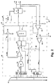
- FIG. 1 is a block diagram of an implantable cardiac defibrillator constructed in accordance with the principles of the present invention.
- Figure 2 is a schematic diagram of the monitor block and its association with the high voltage regulation block of the cardiac defibrillator of Fig. 1.
- the defibrillator synchronizes charging to the timing of the heart by awaiting a sense event before beginning to charge. If there is a leakage from the output stage, synchronizing the beginning of the charge to the R-wave of the cardiac electrogram reduces the probability of causing or exacerbating an arrhythmia. Furthermore, the defibrillator output is monitored in one of a variety of ways to detect and report if leakage current to the patient is unacceptably high.
- the defibrillator output to the patient is monitored directly by a circuit which senses voltage. If the voltage at the patient due to current leakage exceeds some value, e.g. 500 millivolts, the charging episode is terminated. If the voltage at the patient remains below the threshold value, charging is allowed to continue normally. If the charging terminates due to a voltage detected at the patient due to current leakage, the information is stored for subsequent retrieval by the physician.
- some value e.g. 500 millivolts
- a resistor in series with the output stage and the patient may be monitored to directly measure the leakage current.
- a brief (approximately 100 msec, or some other period shorter than the natural refractory period of the heart), synchronized test charge is performed prior to the full capacitor charge.
- the voltage on the high voltage capacitors is measured immediately following the brief test charge.
- a second voltage measurement is performed. The difference in voltages is indicative of the current escaping from the high voltage capacitors. If the second voltage measurement is unacceptably low, the charging episode is aborted on the likely assumption that leakage current to the patient is dangerously high. If the second voltage measurement is above the threshold value, then the charging is allowed to continue normally.
- a charging episode could also be routinely performed by the physician during regularly scheduled follow-up visits. If the output stage integrity is found to be compromised an immediate device replacement would be recommended.
- the block diagram for the implantable defibrillator (shown in Figure 1) includes integrated circuits and a set of high voltage discretes.
- the battery 10 produces a positive voltage with respect to ground that varies from about 6.4 volts when new, to 5.0 volts at the end of service.
- the battery directly powers IC2 30 and the high voltage discretes 60.
- IC2 contains a band-gap reference circuit 31 that produces 1.235 volts, and a 3 volt regulator 32 that powers the microprocessor 90 and IC1 70 through line 100.
- the microprocessor 90 communicates with IC2 30 through a data and address bus 83 and an on-chip interface 34 that contains chip-select, address decoding and data bus logic as is typically used with microprocessor peripherals.
- the internal bus 35 allows the microprocessor to control a general purpose ADC 36, the ventricular pace circuits 38, and the HV control and regulate block 39.
- the ADC 36 is used to measure the battery, high voltage capacitor, and other voltages in the device.
- the ventricular pace circuits 38 include a digital to analog converter that provides the ability to pace at regulated voltages. It communicates with the ventricle of a heart 40 through two lines. One line 43 is a switchable ground; the other line 44 is the pacing cathode and is also the input to the ventricular sense amplifier, as will be described below.
- the ventricular pace lines pass through high voltage protection circuits 45 to keep the defibrillation voltages generated by the device from damaging the pacing circuits 38.
- the HV control and regulate block 39 on IC2 30 is used by the microprocessor 90 to charge a high voltage capacitor included in the HV charge block 46 to a regulated voltage, and then to deliver the defibrillating pulse to the heart 40 through the action of switches in the HV delivery block 47.
- An HV sense line 48 is used by the HV regulation circuits 39 to monitor the defibrillating voltage during charging.
- An HV control bus 49 is used by the HV control circuits 39 to control the switches in the HV delivery block 47 for delivering the defibrillating pulse to the electrodes 52, 53 through lines 50 and 51.
- a monitor 80 which is the subject of this invention, receives inputs from the defibrillating output 50 and 51. The action of the monitor is described in detail below.
- IC1 70 is also a microprocessor peripheral and provides timing, interrupt, telemetry, and sensing functions.
- An electrogram sensing and waveform analysis section 71 interfaces with the ventricle of the heart 40 through line 44.
- the sensed electrogram is amplified and filtered.
- the amplifiers contained in this section 71 have multiple gain settings that are under microprocessor control for maintaining an automatic gain control.
- Features such as peak voltage and complex width are extracted by the waveform analysis circuits 71 for the microprocessor 90 to use in discriminating arrhythmias from normal sinus rhythm.
- the crystal and monitor block 78 has a 100 KHz crystal oscillator that provides clocks to the entire system.
- the monitor is a conventional R-C oscillator that provides a back-up clock if the crystal should fail.
- the microprocessor communicates with IC1 through two buses, 83 and 84.
- One bus 83 is a conventional data and address bus and goes to an on-chip interface 81 that contains chip select, address decoding and data bus drivers as are typically used with microprocessor peripherals.
- the other bus 84 is a control bus. It allows the microprocessor to set up a variety of maskable interrupts for events like timer timeouts, and sense events. If an interrupt is not masked, and the corresponding event occurs, an interrupt is sent from IC1 70 to the microprocessor 90 to alert it of the occurrence.
- the up control and interrupt section 79 contains microprocessor controllable timers and interrupt logic.
- the device can communicate with the outside world through a telemetry interface 74.
- a coil 115 is used in a conventional fashion to transmit and receive pulsed signals.
- the telemetry circuits 74 decode an incoming bit stream from an external coil 110 and hold the data for subsequent retrieval by the microprocessor 90.
- the circuit 74 receives data from the microprocessor 90, encodes it, and provides the timing to pulse the coil 115.
- the communication function is used to retrieve data from the implanted device, and to change the modality of operation if required.
- the microprocessor 90 is of conventional architecture comprising a CPU 91, a ROM 92, a RAM 93, and interface circuits 94.
- the ROM 92 contains the program code that determines the operation of the device.
- the RAM 93 is used to modify the operating characteristics of the device as regards modality, pulse widths, pulse amplitudes, and so forth. Diagnostic data is also stored in the RAM for subsequent transmission to the outside world.
- the Central Processing Unit (ALU) 91 performs the logical operations directed by the program code in the ROM.
- the monitor block 80 and its association with the HV regulate block 39 is shown in greater detail in Figure 2.
- the microprocessor When the microprocessor initiates a charging sequence, it writes to latch 391.
- the address is decoded by the interface circuit 34 and strobes into the latch 391 the voltage and a command to start charging which is directed to the charging controller 395 through line 398.
- the charging episode may be commanded through the external coil 110, or may be automatic in response to a detected arrhythmia. However, in all events, in the preferred embodiment, the start of charging is synchronized to the heart.
- the digital representation of the programmed voltage is sent along bus 400 to the DAC 392, which outputs an analog voltage to a comparator 393.
- the controller is designed to keep the DC-to-DC converter 461 turned on as long as the comparator output 397 remains high, the command from the microprocessor control latch on line 398 is high, and no fault is detected on line 803. Therefore, the DC-to-DC converter will keep charging the high voltage energy storage capacitor 462 until the desired voltage is reached as indicated by HV sense 48 exceeding the DAC output 397.
- HV sense 48 is related to the voltage on the capacitor 462 by the attenuation factor set by the resistor divider 394; this is typically a factor of 500.
- the controller terminates charging, it outputs a signal on line 399 which is available in the status latch 396 for the microprocessor 90 to read.
- the gain of the amplifier 801 sets the voltage value at the patient which is considered a fault. For the preferred embodiment, with a reference voltage of 1.235 volts, and a maximum desired voltage at the patient of 500 millivolts, the gain of the amplifier 801 is set at 2.47. Line 803 from the comparator goes to the status latch 396 and the controller 395. In the latter, the signal causes charging to terminate. In the former, it is latched into the status latch 396 for the microprocessor 90 to read.
- the voltage at the patient is directly monitored.
- other methods of monitoring are also possible.
- the voltage across a resistor placed in series with the patient could be monitored; or the voltage on the high voltage capacitor after a synchronous test charge could be monitored to observe excessive capacitor droop which would be indicative of excessive current leakage to the patient.
Abstract
Description
- The present invention concerns a novel implantable cardiac defibrillator having a current leakage detecting means.
- It is believed that the first implantable defibrillator was implanted in a patient in 1980. Currently, thousands of individuals have devices implanted to correct cardiac conditions involving lethal tachyarrhythmias. It is anticipated that approximately 20,000 patients a year will receive these devices by the mid 1990's. As the use of the implantable defibrillator becomes more prevalent, insuring the safety of the device becomes more crucial.
- A structure common to all implantable defibrillators is the high voltage output stage. Typically it is the interface between the high voltage energy storage capacitor (which is charged by a DC to DC converter) and the patient. An example of this is disclosed in US Patent No. 4,800,883.
- A serious hazard to the patient exists if the electronic switches used in the output stage fail such that one or more becomes a comparatively low resistance. If this should occur, the output of the DC to DC converter is connected directly to the patient during high voltage capacitor charging. The resultant current flowing through the heart of the patient can initiate or accelerate an arrhythmia, cause direct tissue damage, or possibly result in death. While U.S. Patent No. 4,164,946 refers to a fault detecting mechanism, this particular problem is not addressed. Furthermore, no currently available defibrillator incorporates an effective mechanism to guard against this hazard.
- It is an object of this invention to provide a mechanism for preventing the high voltage charging circuit from being connected directly to the patient.
- It is an additional object of this invention to provide the physician with a means to verify the integrity of the defibrillation output stage without delivering a shock to the patient.
- Other objects and advantages of the invention will become apparent as the description proceeds.
- In accordance with the present invention, an implantable cardiac defibrillator is provided. The defibrillator includes an energy source, energy storage means, and means coupled to the energy source for charging the energy storage means. Means are provided for coupling the energy storage means to a patient's heart, by delivering a high voltage shock to the heart. Means are provided for detecting current leakage from the energy storage means. Means responsive to the detecting means are provided for altering the charging of the energy storage means if the current leakage exceeds a predetermined amount.
- In the illustrative embodiment, the altering means comprises means for terminating the charging.
- In one embodiment, the detecting means comprises means for directly sensing voltage at the patient. In another embodiment, the detecting means comprises means for sensing the voltage across a resistance located in series with the patient.
- In a further embodiment, means are provided for providing a test charge for a short interval. The detecting means comprises means for sensing the energy storage means to determine excessive loss of energy after the test charge. In this embodiment, the test charge providing means comprises means for providing an external command to perform the test charge for a period shorter than the natural refractory period of the heart.
- In the illustrative embodiment, means are provided for synchronizing charging of the energy storage means to a sensed R-wave.
- In an illustrative embodiment, the altering means comprises means for comparing a representation of the output from the detecting means to a reference voltage and for altering the charging of the energy storage means if the comparison indicates a fault. In an illustrative embodiment, the implantable cardiac defibrillator includes data storage means, and means responsive to the detecting means for storing current leakage information in the data storage means.
- In accordance with a method of the present invention, a method is provided for operating an implantable cardiac defibrillator having an energy source, energy storage means, means coupled to the energy source for charging the energy storage means, and means for coupling the energy storage means to a patient's heart. The method includes the steps of detecting current leakage from the energy storage means and altering the charging of the energy storage means if the current leakage exceeds a predetermined amount.
- In the illustrative embodiment, an external command is provided to provide a test charge to the energy storage means for a short interval. A first measurement of the voltage on the energy storage means is performed. At a predetermined time thereafter, a second measurement of the voltage on the energy storage means is performed. If the first voltage measurement exceeds the second voltage measurement by a predetermined amount, then the operation of the charging means is altered.
- A more detailed explanation of the invention is provided in the following description and claims, and is illustrated in the accompanying drawings.
- Figure 1 is a block diagram of an implantable cardiac defibrillator constructed in accordance with the principles of the present invention.
- Figure 2 is a schematic diagram of the monitor block and its association with the high voltage regulation block of the cardiac defibrillator of Fig. 1.
- In an illustrative embodiment of the present invention, the defibrillator synchronizes charging to the timing of the heart by awaiting a sense event before beginning to charge. If there is a leakage from the output stage, synchronizing the beginning of the charge to the R-wave of the cardiac electrogram reduces the probability of causing or exacerbating an arrhythmia. Furthermore, the defibrillator output is monitored in one of a variety of ways to detect and report if leakage current to the patient is unacceptably high.
- In one embodiment, the defibrillator output to the patient is monitored directly by a circuit which senses voltage. If the voltage at the patient due to current leakage exceeds some value, e.g. 500 millivolts, the charging episode is terminated. If the voltage at the patient remains below the threshold value, charging is allowed to continue normally. If the charging terminates due to a voltage detected at the patient due to current leakage, the information is stored for subsequent retrieval by the physician.
- Alternatively, a resistor in series with the output stage and the patient may be monitored to directly measure the leakage current.
- In another embodiment, a brief (approximately 100 msec, or some other period shorter than the natural refractory period of the heart), synchronized test charge is performed prior to the full capacitor charge. The voltage on the high voltage capacitors is measured immediately following the brief test charge. At some known interval following the first voltage measurement, a second voltage measurement is performed. The difference in voltages is indicative of the current escaping from the high voltage capacitors. If the second voltage measurement is unacceptably low, the charging episode is aborted on the likely assumption that leakage current to the patient is dangerously high. If the second voltage measurement is above the threshold value, then the charging is allowed to continue normally.
- In addition to being performed automatically, a charging episode could also be routinely performed by the physician during regularly scheduled follow-up visits. If the output stage integrity is found to be compromised an immediate device replacement would be recommended.
- The block diagram for the implantable defibrillator (shown in Figure 1) includes integrated circuits and a set of high voltage discretes. The battery 10 produces a positive voltage with respect to ground that varies from about 6.4 volts when new, to 5.0 volts at the end of service. The battery directly powers
IC2 30 and the high voltage discretes 60. - IC2 contains a band-
gap reference circuit 31 that produces 1.235 volts, and a 3volt regulator 32 that powers the microprocessor 90 and IC1 70 through line 100. The microprocessor 90 communicates withIC2 30 through a data andaddress bus 83 and an on-chip interface 34 that contains chip-select, address decoding and data bus logic as is typically used with microprocessor peripherals. Theinternal bus 35 allows the microprocessor to control ageneral purpose ADC 36, theventricular pace circuits 38, and the HV control and regulateblock 39. TheADC 36 is used to measure the battery, high voltage capacitor, and other voltages in the device. - The
ventricular pace circuits 38 include a digital to analog converter that provides the ability to pace at regulated voltages. It communicates with the ventricle of aheart 40 through two lines. Oneline 43 is a switchable ground; theother line 44 is the pacing cathode and is also the input to the ventricular sense amplifier, as will be described below. - The ventricular pace lines pass through high
voltage protection circuits 45 to keep the defibrillation voltages generated by the device from damaging thepacing circuits 38. The HV control and regulateblock 39 onIC2 30 is used by the microprocessor 90 to charge a high voltage capacitor included in theHV charge block 46 to a regulated voltage, and then to deliver the defibrillating pulse to theheart 40 through the action of switches in theHV delivery block 47. AnHV sense line 48 is used by theHV regulation circuits 39 to monitor the defibrillating voltage during charging. AnHV control bus 49 is used by theHV control circuits 39 to control the switches in theHV delivery block 47 for delivering the defibrillating pulse to theelectrodes 52, 53 throughlines - A
monitor 80, which is the subject of this invention, receives inputs from the defibrillatingoutput - IC1 70 is also a microprocessor peripheral and provides timing, interrupt, telemetry, and sensing functions.
- An electrogram sensing and
waveform analysis section 71 interfaces with the ventricle of theheart 40 throughline 44. The sensed electrogram is amplified and filtered. The amplifiers contained in thissection 71 have multiple gain settings that are under microprocessor control for maintaining an automatic gain control. Features such as peak voltage and complex width are extracted by thewaveform analysis circuits 71 for the microprocessor 90 to use in discriminating arrhythmias from normal sinus rhythm. - The crystal and monitor
block 78 has a 100 KHz crystal oscillator that provides clocks to the entire system. The monitor is a conventional R-C oscillator that provides a back-up clock if the crystal should fail. - The microprocessor communicates with IC1 through two buses, 83 and 84. One
bus 83 is a conventional data and address bus and goes to an on-chip interface 81 that contains chip select, address decoding and data bus drivers as are typically used with microprocessor peripherals. Theother bus 84 is a control bus. It allows the microprocessor to set up a variety of maskable interrupts for events like timer timeouts, and sense events. If an interrupt is not masked, and the corresponding event occurs, an interrupt is sent from IC1 70 to the microprocessor 90 to alert it of the occurrence. On IC1 70, the up control and interruptsection 79 contains microprocessor controllable timers and interrupt logic. - The device can communicate with the outside world through a
telemetry interface 74. Acoil 115 is used in a conventional fashion to transmit and receive pulsed signals. Thetelemetry circuits 74 decode an incoming bit stream from anexternal coil 110 and hold the data for subsequent retrieval by the microprocessor 90. When used for transmitting, thecircuit 74 receives data from the microprocessor 90, encodes it, and provides the timing to pulse thecoil 115. The communication function is used to retrieve data from the implanted device, and to change the modality of operation if required. - The microprocessor 90 is of conventional architecture comprising a
CPU 91, aROM 92, aRAM 93, andinterface circuits 94. TheROM 92 contains the program code that determines the operation of the device. TheRAM 93 is used to modify the operating characteristics of the device as regards modality, pulse widths, pulse amplitudes, and so forth. Diagnostic data is also stored in the RAM for subsequent transmission to the outside world. The Central Processing Unit (ALU) 91 performs the logical operations directed by the program code in the ROM. - The
monitor block 80 and its association with the HV regulateblock 39 is shown in greater detail in Figure 2. When the microprocessor initiates a charging sequence, it writes to latch 391. The address is decoded by theinterface circuit 34 and strobes into thelatch 391 the voltage and a command to start charging which is directed to the chargingcontroller 395 throughline 398. The charging episode may be commanded through theexternal coil 110, or may be automatic in response to a detected arrhythmia. However, in all events, in the preferred embodiment, the start of charging is synchronized to the heart. - The digital representation of the programmed voltage is sent along bus 400 to the
DAC 392, which outputs an analog voltage to acomparator 393. As long asHV sense 48 is less than the voltage online 401 the output of thecomparator 397 remains high. The controller is designed to keep the DC-to-DC converter 461 turned on as long as thecomparator output 397 remains high, the command from the microprocessor control latch online 398 is high, and no fault is detected on line 803. Therefore, the DC-to-DC converter will keep charging the high voltageenergy storage capacitor 462 until the desired voltage is reached as indicated byHV sense 48 exceeding theDAC output 397.HV sense 48 is related to the voltage on thecapacitor 462 by the attenuation factor set by theresistor divider 394; this is typically a factor of 500. When the controller terminates charging, it outputs a signal online 399 which is available in thestatus latch 396 for the microprocessor 90 to read. - In the absence of a failure in the
HV delivery circuits 47, very little current leaks from thecapacitor 462 through theleads heart 40. If current does leak to the patient, a voltage will be generated by the current flowing through the resistance of the patient'sheart 40 and will be detected by the differential amplifier 801. If the output of the amplifier 804 exceeds thereference voltage 72 the comparator 802 output 803 will go high. Therefore, for a fixed reference voltage, the gain of the amplifier 801 sets the voltage value at the patient which is considered a fault. For the preferred embodiment, with a reference voltage of 1.235 volts, and a maximum desired voltage at the patient of 500 millivolts, the gain of the amplifier 801 is set at 2.47. Line 803 from the comparator goes to thestatus latch 396 and thecontroller 395. In the latter, the signal causes charging to terminate. In the former, it is latched into thestatus latch 396 for the microprocessor 90 to read. - In the preferred embodiment the voltage at the patient is directly monitored. However, as will occur to those skilled in the art, other methods of monitoring are also possible. Alternatively, the voltage across a resistor placed in series with the patient could be monitored; or the voltage on the high voltage capacitor after a synchronous test charge could be monitored to observe excessive capacitor droop which would be indicative of excessive current leakage to the patient.
- Although illustrative embodiments of the invention have been shown and described, it is to be understood that various modifications and substitutions may be made by those skilled in the art without departing from the novel spirit and scope of the present invention.
Claims (10)
- An implantable cardiac defibrillator which comprises:
an energy source;
energy storage means;
means coupled to said energy source for charging said energy storage means;
means for coupling said energy storage means to a patient's heart, for delivering a high voltage shock to the heart;
means for detecting current leakage from said energy storage means; and
means responsive to said detecting means for altering the charging of said energy storage means if the current leakage exceeds a predetermined amount. - An implantable cardiac defibrillator as defined by claim 1, in which said altering means comprises means for terminating the charging.
- An implantable cardiac defibrillator as defined by claim 1, said detecting means comprising means for directly sensing voltage at the patient.
- An implantable cardiac defibrillator as defined by claim 1, said detecting means comprising means for sensing the voltage across a resistance located in series with the patient.
- An implantable cardiac defibrillator as defined by claim 1, said detecting means comprising means for sensing said energy storage means to determine excessive loss of energy.
- An implantable cardiac defibrillator as defined by claim 1, said altering means comprising means for comparing a representation of the output from said detecting means to a reference voltage and for altering the charging of said energy storage means if the comparison indicates a fault.
- An implantable cardiac defibrillator which comprises:
an energy source;
energy storage means;
means coupled to said energy source for charging said energy storage means;
means for coupling said energy storage means to a patient's heart for delivering a high voltage shock to the heart;
means for detecting current leakage from said energy storage means;
means responsive to said detecting means for altering the charging of said energy storage means if the current leakage exceeds a predetermined amount;
means for providing a test charge for a short interval, said detecting means comprising means for sensing said energy storage means to determine excessive loss of energy after said test charge;
said test charge providing means comprising means for providing an external command to perform the test charge for a period shorter than the natural refractory period of the heart;
means for synchronizing charging of said energy storage means to a sensed cardiac event; and
means for reporting status. - An implantable cardiac defibrillator which comprises:
a battery;
capacitive means;
means coupled to said battery for charging said capacitive means;
means for coupling said capacitive means to a patient's heart for delivering a high voltage shock to the heart;
means for synchronizing charging of said capacitive means to a sensed R-wave;
means for detecting current leakage from said capacitive means;
means responsive to said detecting means for altering the charging of said capacitive means if the current leakage exceeds a predetermined amount;
said altering means comprising means for comparing a representation of the output from said detecting means to a reference voltage and for altering the charging of said capacitive means if the comparison indicates a fault. - A method for operating an implantable cardiac defibrillator having an energy source, energy storage means, means coupled to said energy source for charging said energy storage means, and means for coupling said energy storage means to a patient's heart, including the steps of:
detecting current leakage from said energy storage means; and
altering the charging of said energy storage means if the current leakage exceeds a predetermined amount. - A method for operating an implantable cardiac defibrillator having an energy source, energy storage means, means coupled to said energy source for charging said energy storage means, means for coupling said energy storage means to a patient's heart, including the steps of:
providing an external command to provide a test charge to said energy storage means for a short interval;
performing a first measurement of the voltage on the energy storage means;
at a predetermined time thereafter, performing a second measurement of the voltage on the energy storage means;
if the first voltage measurement exceeds the second voltage measurement by a predetermined amount, then altering the operation of said charging means.
Applications Claiming Priority (2)
| Application Number | Priority Date | Filing Date | Title |
|---|---|---|---|
| US597204 | 1990-10-11 | ||
| US07/597,204 US5163428A (en) | 1990-10-11 | 1990-10-11 | Implantable cardiac defibrillator with current leakage detecting means |
Publications (3)
| Publication Number | Publication Date |
|---|---|
| EP0480569A2 true EP0480569A2 (en) | 1992-04-15 |
| EP0480569A3 EP0480569A3 (en) | 1992-10-21 |
| EP0480569B1 EP0480569B1 (en) | 1996-12-04 |
Family
ID=24390539
Family Applications (1)
| Application Number | Title | Priority Date | Filing Date |
|---|---|---|---|
| EP91307695A Expired - Lifetime EP0480569B1 (en) | 1990-10-11 | 1991-08-21 | Implantable cardiac defibrillator with current leakage detecting means |
Country Status (7)
| Country | Link |
|---|---|
| US (1) | US5163428A (en) |
| EP (1) | EP0480569B1 (en) |
| AT (1) | ATE145831T1 (en) |
| CA (1) | CA2050088C (en) |
| DE (1) | DE69123429T2 (en) |
| DK (1) | DK0480569T3 (en) |
| ES (1) | ES2097189T3 (en) |
Cited By (7)
| Publication number | Priority date | Publication date | Assignee | Title |
|---|---|---|---|---|
| EP0574608A1 (en) * | 1992-06-17 | 1993-12-22 | Pacesetter AB | Defibrillator/cardioverter |
| EP0574609A1 (en) * | 1992-06-17 | 1993-12-22 | Pacesetter AB | Defibrillator/cardioverter |
| EP0589610A2 (en) * | 1992-09-16 | 1994-03-30 | Pacesetter, Inc. | Method and apparatus for capacitor tolerance compensation in a cardiac stimulating device |
| WO1995009673A1 (en) * | 1993-10-06 | 1995-04-13 | Duke University | Method and apparatus for delivering a shock with an optimum duration in treating arrhythmias |
| EP0753327A2 (en) * | 1995-07-13 | 1997-01-15 | Pacesetter, Inc. | Safety optimization in microprocessor-controlled implantable devices |
| US7089057B2 (en) | 2002-04-26 | 2006-08-08 | Medtronic, Inc. | Detection of possible failure of capacitive elements in an implantable medical device |
| US7158825B1 (en) | 2003-02-24 | 2007-01-02 | Pacesetter, Inc. | Implantable cardioverter defibrillator with leakage detection and prevention system |
Families Citing this family (53)
| Publication number | Priority date | Publication date | Assignee | Title |
|---|---|---|---|---|
| EP0598225B1 (en) * | 1992-11-19 | 2001-01-03 | Cardiac Pacemakers, Inc. | System for constant charge time of a defibrillation capacitor and for its discharge |
| US5431684A (en) * | 1993-12-22 | 1995-07-11 | Ventritex, Inc. | Implantable defibrillator output stage test circuit and method |
| US5575807A (en) * | 1994-06-10 | 1996-11-19 | Zmd Corporation | Medical device power supply with AC disconnect alarm and method of supplying power to a medical device |
| US5470343A (en) * | 1994-06-10 | 1995-11-28 | Zmd Corporation | Detachable power supply for supplying external power to a portable defibrillator |
| US5620469A (en) * | 1994-10-11 | 1997-04-15 | Angeion Corporation | Stepped cardioversion system for an implantable cardioverter defibrillator |
| US5709710A (en) * | 1995-05-10 | 1998-01-20 | Armstrong; Randolph Kerry | Implantable cardioverter/defibrillator with adaptive shock coupling interval and method |
| IL125424A0 (en) | 1998-07-20 | 1999-03-12 | New Technologies Sa Ysy Ltd | Pacing with hemodynamic enhancement |
| US9289618B1 (en) | 1996-01-08 | 2016-03-22 | Impulse Dynamics Nv | Electrical muscle controller |
| US8321013B2 (en) | 1996-01-08 | 2012-11-27 | Impulse Dynamics, N.V. | Electrical muscle controller and pacing with hemodynamic enhancement |
| IL125136A (en) | 1996-01-08 | 2003-07-31 | Impulse Dynamics Nv | Electrical cardiac muscle controller method and apparatus |
| US8825152B2 (en) | 1996-01-08 | 2014-09-02 | Impulse Dynamics, N.V. | Modulation of intracellular calcium concentration using non-excitatory electrical signals applied to the tissue |
| US7167748B2 (en) | 1996-01-08 | 2007-01-23 | Impulse Dynamics Nv | Electrical muscle controller |
| US9713723B2 (en) | 1996-01-11 | 2017-07-25 | Impulse Dynamics Nv | Signal delivery through the right ventricular septum |
| US5899923A (en) * | 1996-03-22 | 1999-05-04 | Angeion Corporation | Automatic capacitor maintenance system for an implantable cardioverter defibrillator |
| US7840264B1 (en) | 1996-08-19 | 2010-11-23 | Mr3 Medical, Llc | System and method for breaking reentry circuits by cooling cardiac tissue |
| US7908003B1 (en) | 1996-08-19 | 2011-03-15 | Mr3 Medical Llc | System and method for treating ischemia by improving cardiac efficiency |
| US5797967A (en) * | 1996-09-27 | 1998-08-25 | Cardiac Pacemakers, Inc. | System and method to reduce defibrillation requirements |
| US5974339A (en) * | 1997-11-26 | 1999-10-26 | Procath Corporation | High energy defibrillator employing current control circuitry |
| US6463334B1 (en) | 1998-11-02 | 2002-10-08 | Cardiac Pacemakers, Inc. | Extendable and retractable lead |
| US6501990B1 (en) | 1999-12-23 | 2002-12-31 | Cardiac Pacemakers, Inc. | Extendable and retractable lead having a snap-fit terminal connector |
| US6911201B1 (en) | 1999-02-04 | 2005-06-28 | Technion Research & Development Foundation Ltd. | Method of producing undifferentiated hemopoietic stem cells using a stationary phase plug-flow bioreactor |
| US8666495B2 (en) | 1999-03-05 | 2014-03-04 | Metacure Limited | Gastrointestinal methods and apparatus for use in treating disorders and controlling blood sugar |
| US8700161B2 (en) | 1999-03-05 | 2014-04-15 | Metacure Limited | Blood glucose level control |
| US9101765B2 (en) | 1999-03-05 | 2015-08-11 | Metacure Limited | Non-immediate effects of therapy |
| US8019421B2 (en) | 1999-03-05 | 2011-09-13 | Metacure Limited | Blood glucose level control |
| US8346363B2 (en) | 1999-03-05 | 2013-01-01 | Metacure Limited | Blood glucose level control |
| US7027863B1 (en) | 1999-10-25 | 2006-04-11 | Impulse Dynamics N.V. | Device for cardiac therapy |
| US6993385B1 (en) | 1999-10-25 | 2006-01-31 | Impulse Dynamics N.V. | Cardiac contractility modulation device having anti-arrhythmic capabilities and a method of operating thereof |
| WO2001030445A1 (en) | 1999-10-25 | 2001-05-03 | Impulse Dynamics N.V. | Cardiac contractility modulation device having anti-arrhythmic capabilities and a method of operating thereof |
| US6421563B1 (en) | 2000-03-01 | 2002-07-16 | Medtronic Physio-Control Manufacturing Corp. | Solid-state multiphasic defibrillation circuit |
| US6847842B1 (en) | 2000-05-15 | 2005-01-25 | Cardiac Pacemakers, Inc. | Method and apparatus for reducing early recurrence of atrial fibrillation with defibrillation shock therapy |
| KR100370164B1 (en) * | 2000-12-20 | 2003-01-30 | 주식회사 하이닉스반도체 | Pull-up Scheme Compensable Leakage Current in Bit Lines |
| US6898463B2 (en) * | 2002-03-19 | 2005-05-24 | Medtronic, Inc. | Current monitor for an implantable medical device |
| US20030191505A1 (en) * | 2002-04-09 | 2003-10-09 | Mark Gryzwa | Magnetic structure for feedthrough filter assembly |
| US6945331B2 (en) * | 2002-07-31 | 2005-09-20 | Schlumberger Technology Corporation | Multiple interventionless actuated downhole valve and method |
| US7372455B2 (en) | 2003-02-10 | 2008-05-13 | N-Trig Ltd. | Touch detection for a digitizer |
| US11439815B2 (en) | 2003-03-10 | 2022-09-13 | Impulse Dynamics Nv | Protein activity modification |
| EP1606011B1 (en) | 2003-03-10 | 2015-08-19 | Impulse Dynamics N.V. | Apparatus for delivering electrical signals to modify gene expression in cardiac tissue |
| US8792985B2 (en) | 2003-07-21 | 2014-07-29 | Metacure Limited | Gastrointestinal methods and apparatus for use in treating disorders and controlling blood sugar |
| US7719854B2 (en) | 2003-07-31 | 2010-05-18 | Cardiac Pacemakers, Inc. | Integrated electromagnetic interference filters and feedthroughs |
| WO2006119467A2 (en) | 2005-05-04 | 2006-11-09 | Impulse Dynamics Nv | Protein activity modification |
| US8352031B2 (en) | 2004-03-10 | 2013-01-08 | Impulse Dynamics Nv | Protein activity modification |
| US11779768B2 (en) | 2004-03-10 | 2023-10-10 | Impulse Dynamics Nv | Protein activity modification |
| EP1827571B1 (en) | 2004-12-09 | 2016-09-07 | Impulse Dynamics NV | Protein activity modification |
| US9821158B2 (en) | 2005-02-17 | 2017-11-21 | Metacure Limited | Non-immediate effects of therapy |
| US8244371B2 (en) | 2005-03-18 | 2012-08-14 | Metacure Limited | Pancreas lead |
| US7877139B2 (en) * | 2006-09-22 | 2011-01-25 | Cameron Health, Inc. | Method and device for implantable cardiac stimulus device lead impedance measurement |
| US8934975B2 (en) | 2010-02-01 | 2015-01-13 | Metacure Limited | Gastrointestinal electrical therapy |
| US20110245888A1 (en) * | 2010-04-05 | 2011-10-06 | Pacesetter, Inc. | Medical device with charge leakage detection |
| US10117292B2 (en) * | 2013-04-19 | 2018-10-30 | Chromalox, Inc. | Medium voltage heater elements moisture detection circuit |
| EP3708218A1 (en) * | 2014-06-21 | 2020-09-16 | Nalu Medical, Inc. | Apparatus for neuromodulation treatments of pain and other conditions |
| US10159847B2 (en) | 2015-05-20 | 2018-12-25 | Medtronic, Inc. | Implantable medical devices with active component monitoring |
| WO2020010001A1 (en) | 2018-07-06 | 2020-01-09 | Cardiac Pacemakers, Inc. | Adjustable sensing in a his-bundle pacemaker |
Citations (9)
| Publication number | Priority date | Publication date | Assignee | Title |
|---|---|---|---|---|
| US4119903A (en) * | 1978-01-05 | 1978-10-10 | Hewlett-Packard Company | Defibrillator charging circuit |
| EP0060404A2 (en) * | 1981-03-12 | 1982-09-22 | Hellige GmbH | Defibrillator |
| EP0228539A1 (en) * | 1985-11-20 | 1987-07-15 | Intermedics, Inc. | Protection apparatus for patient-implantable device |
| EP0299338A2 (en) * | 1987-07-11 | 1989-01-18 | Nihon Kohden Corporation | Defibrillator |
| US4800883A (en) * | 1986-04-02 | 1989-01-31 | Intermedics, Inc. | Apparatus for generating multiphasic defibrillation pulse waveform |
| US4823796A (en) * | 1987-04-03 | 1989-04-25 | Laerdal Manufacturing Corp. | Defibrillator circuit for producing a trapezoidal defibrillation pulse |
| EP0324380A1 (en) * | 1988-01-12 | 1989-07-19 | Mirowski, Mieczyslaw | Biphasic pulse generator for an implantable defibrillator |
| EP0362093A2 (en) * | 1988-07-06 | 1990-04-04 | ATESYS, société anonyme | Charge-dicharge circuit for the condensator of a defibrillator |
| US4949719A (en) * | 1989-04-26 | 1990-08-21 | Ventritex, Inc. | Method for cardiac defibrillation |
Family Cites Families (11)
| Publication number | Priority date | Publication date | Assignee | Title |
|---|---|---|---|---|
| DE2340123A1 (en) * | 1973-08-08 | 1975-02-20 | Schwarzer Gmbh Fritz | OVERCURRENT PROTECTION CIRCUIT |
| US4080558A (en) * | 1974-12-30 | 1978-03-21 | Gould Inc. | Defibrillator battery charger |
| US4088141A (en) * | 1976-04-27 | 1978-05-09 | Stimulation Technology, Inc. | Fault circuit for stimulator |
| DE2651031C2 (en) * | 1976-11-09 | 1982-04-01 | Bruker Medizintechnik Gmbh, 7512 Rheinstetten | Defibrillator |
| US4102347A (en) * | 1976-12-03 | 1978-07-25 | Yukl Tex N | Electronic pain control system |
| US4164946A (en) * | 1977-05-27 | 1979-08-21 | Mieczyslaw Mirowski | Fault detection circuit for permanently implanted cardioverter |
| US4364396A (en) * | 1981-06-15 | 1982-12-21 | Medtronic, Inc. | Circuit and method for measuring PSA output and energy |
| US4559946A (en) * | 1982-06-18 | 1985-12-24 | Mieczyslaw Mirowski | Method and apparatus for correcting abnormal cardiac activity by low energy shocks |
| DE3523871C3 (en) * | 1985-07-04 | 1994-07-28 | Erbe Elektromedizin | High frequency surgical device |
| US4800833A (en) * | 1986-10-28 | 1989-01-31 | Shih Nan C | Tubular door lock with a bell |
| US5111816A (en) * | 1989-05-23 | 1992-05-12 | Ventritex | System configuration for combined defibrillator/pacemaker |
-
1990
- 1990-10-11 US US07/597,204 patent/US5163428A/en not_active Expired - Lifetime
-
1991
- 1991-08-21 DE DE69123429T patent/DE69123429T2/en not_active Expired - Fee Related
- 1991-08-21 DK DK91307695.6T patent/DK0480569T3/en active
- 1991-08-21 EP EP91307695A patent/EP0480569B1/en not_active Expired - Lifetime
- 1991-08-21 ES ES91307695T patent/ES2097189T3/en not_active Expired - Lifetime
- 1991-08-21 AT AT91307695T patent/ATE145831T1/en not_active IP Right Cessation
- 1991-08-28 CA CA002050088A patent/CA2050088C/en not_active Expired - Fee Related
Patent Citations (9)
| Publication number | Priority date | Publication date | Assignee | Title |
|---|---|---|---|---|
| US4119903A (en) * | 1978-01-05 | 1978-10-10 | Hewlett-Packard Company | Defibrillator charging circuit |
| EP0060404A2 (en) * | 1981-03-12 | 1982-09-22 | Hellige GmbH | Defibrillator |
| EP0228539A1 (en) * | 1985-11-20 | 1987-07-15 | Intermedics, Inc. | Protection apparatus for patient-implantable device |
| US4800883A (en) * | 1986-04-02 | 1989-01-31 | Intermedics, Inc. | Apparatus for generating multiphasic defibrillation pulse waveform |
| US4823796A (en) * | 1987-04-03 | 1989-04-25 | Laerdal Manufacturing Corp. | Defibrillator circuit for producing a trapezoidal defibrillation pulse |
| EP0299338A2 (en) * | 1987-07-11 | 1989-01-18 | Nihon Kohden Corporation | Defibrillator |
| EP0324380A1 (en) * | 1988-01-12 | 1989-07-19 | Mirowski, Mieczyslaw | Biphasic pulse generator for an implantable defibrillator |
| EP0362093A2 (en) * | 1988-07-06 | 1990-04-04 | ATESYS, société anonyme | Charge-dicharge circuit for the condensator of a defibrillator |
| US4949719A (en) * | 1989-04-26 | 1990-08-21 | Ventritex, Inc. | Method for cardiac defibrillation |
Cited By (11)
| Publication number | Priority date | Publication date | Assignee | Title |
|---|---|---|---|---|
| EP0574608A1 (en) * | 1992-06-17 | 1993-12-22 | Pacesetter AB | Defibrillator/cardioverter |
| EP0574609A1 (en) * | 1992-06-17 | 1993-12-22 | Pacesetter AB | Defibrillator/cardioverter |
| US5376105A (en) * | 1992-06-17 | 1994-12-27 | Siemens Aktiengesellschaft | Defibrillator/cardioverter |
| US5397336A (en) * | 1992-06-17 | 1995-03-14 | Siemens Aktiengesellschaft | Defibrillator/cardioverter |
| EP0589610A2 (en) * | 1992-09-16 | 1994-03-30 | Pacesetter, Inc. | Method and apparatus for capacitor tolerance compensation in a cardiac stimulating device |
| EP0589610A3 (en) * | 1992-09-16 | 1997-12-03 | Pacesetter, Inc. | Method and apparatus for capacitor tolerance compensation in a cardiac stimulating device |
| WO1995009673A1 (en) * | 1993-10-06 | 1995-04-13 | Duke University | Method and apparatus for delivering a shock with an optimum duration in treating arrhythmias |
| EP0753327A2 (en) * | 1995-07-13 | 1997-01-15 | Pacesetter, Inc. | Safety optimization in microprocessor-controlled implantable devices |
| EP0753327A3 (en) * | 1995-07-13 | 1998-08-12 | Pacesetter, Inc. | Safety optimization in microprocessor-controlled implantable devices |
| US7089057B2 (en) | 2002-04-26 | 2006-08-08 | Medtronic, Inc. | Detection of possible failure of capacitive elements in an implantable medical device |
| US7158825B1 (en) | 2003-02-24 | 2007-01-02 | Pacesetter, Inc. | Implantable cardioverter defibrillator with leakage detection and prevention system |
Also Published As
| Publication number | Publication date |
|---|---|
| EP0480569B1 (en) | 1996-12-04 |
| EP0480569A3 (en) | 1992-10-21 |
| DE69123429D1 (en) | 1997-01-16 |
| DE69123429T2 (en) | 1997-04-24 |
| DK0480569T3 (en) | 1996-12-23 |
| ATE145831T1 (en) | 1996-12-15 |
| US5163428A (en) | 1992-11-17 |
| CA2050088C (en) | 1998-08-04 |
| ES2097189T3 (en) | 1997-04-01 |
| CA2050088A1 (en) | 1992-04-12 |
Similar Documents
| Publication | Publication Date | Title |
|---|---|---|
| US5163428A (en) | Implantable cardiac defibrillator with current leakage detecting means | |
| US4949719A (en) | Method for cardiac defibrillation | |
| US6185461B1 (en) | System and method for verification of recommended replacement time indication in an implantable cardiac stimulation device | |
| EP0607637B1 (en) | Atrial defibrillator comprising a test mode | |
| US5792201A (en) | Safety optimization in microprocessor-controlled implantable devices | |
| US4475551A (en) | Arrhythmia detection and defibrillation system and method | |
| CA2157645C (en) | Atrial fibrillation type selective cardiovertor and method | |
| US4164946A (en) | Fault detection circuit for permanently implanted cardioverter | |
| US5527345A (en) | Implantable atrial defibrillator having an intermittenly activated pacing modality | |
| US6456883B1 (en) | Apparatus and method for allowing immediate retrieval for information and identification from an implantable medical device having a depleted power source | |
| EP0696462A2 (en) | Atrial defibrillator for providing interval timing of successive intervals prior to cardioversion | |
| EP0528751A1 (en) | Impedance based automatic pulse duration adjustment for defibrillation shock delivery | |
| EP0693301A2 (en) | System and method for reducing false positives in atrial fibrillation detection | |
| US20030004552A1 (en) | Implantable cardioverter/defibrillator | |
| US20040230244A1 (en) | Cardiac rhythm management system with user interface for threshold test | |
| US20050192640A1 (en) | Method and apparatus for implementing task-oriented induction capabilities in an implantable cardioverter defibrillator and programmer | |
| EP0831740A1 (en) | Methods and apparatus for storing intracardiac electrograms | |
| JP2002519131A (en) | System and method for detecting atrial events in the heart using only atrial sensing | |
| US6096062A (en) | Method and apparatus for maintaining a high voltage capacitor in an implantable cardiac device | |
| CA1171912A (en) | Arrythmia detection system and method | |
| EP0770410B1 (en) | An implantable atrial defibrillator having cardioverting output voltage limiting for simulating larger storage capacitors | |
| US5653740A (en) | Method and apparatus for induction of fibrillation | |
| EP0331697B1 (en) | Reconfirmation prior to shock for implantable defibrillation | |
| Fetter et al. | Transtelephonic monitoring and transmission of stored arrhythmia detection and therapy data from an implantable cardioverter defibrillator | |
| Adams | Patient followup systems |
Legal Events
| Date | Code | Title | Description |
|---|---|---|---|
| PUAI | Public reference made under article 153(3) epc to a published international application that has entered the european phase |
Free format text: ORIGINAL CODE: 0009012 |
|
| AK | Designated contracting states |
Kind code of ref document: A2 Designated state(s): AT BE CH DE DK ES FR GB GR IT LI NL SE |
|
| PUAL | Search report despatched |
Free format text: ORIGINAL CODE: 0009013 |
|
| AK | Designated contracting states |
Kind code of ref document: A3 Designated state(s): AT BE CH DE DK ES FR GB GR IT LI NL SE |
|
| 17P | Request for examination filed |
Effective date: 19921120 |
|
| 17Q | First examination report despatched |
Effective date: 19950216 |
|
| GRAG | Despatch of communication of intention to grant |
Free format text: ORIGINAL CODE: EPIDOS AGRA |
|
| GRAH | Despatch of communication of intention to grant a patent |
Free format text: ORIGINAL CODE: EPIDOS IGRA |
|
| GRAH | Despatch of communication of intention to grant a patent |
Free format text: ORIGINAL CODE: EPIDOS IGRA |
|
| GRAA | (expected) grant |
Free format text: ORIGINAL CODE: 0009210 |
|
| AK | Designated contracting states |
Kind code of ref document: B1 Designated state(s): AT BE CH DE DK ES FR GB GR IT LI NL SE |
|
| PG25 | Lapsed in a contracting state [announced via postgrant information from national office to epo] |
Ref country code: GR Free format text: LAPSE BECAUSE OF FAILURE TO SUBMIT A TRANSLATION OF THE DESCRIPTION OR TO PAY THE FEE WITHIN THE PRESCRIBED TIME-LIMIT Effective date: 19961204 |
|
| REF | Corresponds to: |
Ref document number: 145831 Country of ref document: AT Date of ref document: 19961215 Kind code of ref document: T |
|
| REG | Reference to a national code |
Ref country code: CH Ref legal event code: NV Representative=s name: KIRKER & CIE SA |
|
| REG | Reference to a national code |
Ref country code: DK Ref legal event code: T3 |
|
| REF | Corresponds to: |
Ref document number: 69123429 Country of ref document: DE Date of ref document: 19970116 |
|
| ITF | It: translation for a ep patent filed |
Owner name: NOTARBARTOLO & GERVASI S.R.L. |
|
| ET | Fr: translation filed | ||
| REG | Reference to a national code |
Ref country code: ES Ref legal event code: FG2A Ref document number: 2097189 Country of ref document: ES Kind code of ref document: T3 |
|
| PGFP | Annual fee paid to national office [announced via postgrant information from national office to epo] |
Ref country code: AT Payment date: 19970729 Year of fee payment: 7 |
|
| PGFP | Annual fee paid to national office [announced via postgrant information from national office to epo] |
Ref country code: FR Payment date: 19970811 Year of fee payment: 7 |
|
| PGFP | Annual fee paid to national office [announced via postgrant information from national office to epo] |
Ref country code: DK Payment date: 19970815 Year of fee payment: 7 |
|
| PGFP | Annual fee paid to national office [announced via postgrant information from national office to epo] |
Ref country code: SE Payment date: 19970818 Year of fee payment: 7 |
|
| PGFP | Annual fee paid to national office [announced via postgrant information from national office to epo] |
Ref country code: NL Payment date: 19970826 Year of fee payment: 7 |
|
| PGFP | Annual fee paid to national office [announced via postgrant information from national office to epo] |
Ref country code: ES Payment date: 19970828 Year of fee payment: 7 |
|
| PGFP | Annual fee paid to national office [announced via postgrant information from national office to epo] |
Ref country code: CH Payment date: 19970911 Year of fee payment: 7 |
|
| PLBE | No opposition filed within time limit |
Free format text: ORIGINAL CODE: 0009261 |
|
| STAA | Information on the status of an ep patent application or granted ep patent |
Free format text: STATUS: NO OPPOSITION FILED WITHIN TIME LIMIT |
|
| PGFP | Annual fee paid to national office [announced via postgrant information from national office to epo] |
Ref country code: BE Payment date: 19971013 Year of fee payment: 7 |
|
| 26N | No opposition filed | ||
| PGFP | Annual fee paid to national office [announced via postgrant information from national office to epo] |
Ref country code: GB Payment date: 19980812 Year of fee payment: 8 |
|
| PG25 | Lapsed in a contracting state [announced via postgrant information from national office to epo] |
Ref country code: DK Free format text: LAPSE BECAUSE OF NON-PAYMENT OF DUE FEES Effective date: 19980821 Ref country code: AT Free format text: LAPSE BECAUSE OF NON-PAYMENT OF DUE FEES Effective date: 19980821 |
|
| PG25 | Lapsed in a contracting state [announced via postgrant information from national office to epo] |
Ref country code: SE Free format text: LAPSE BECAUSE OF NON-PAYMENT OF DUE FEES Effective date: 19980822 Ref country code: ES Free format text: LAPSE BECAUSE OF EXPIRATION OF PROTECTION Effective date: 19980822 |
|
| PG25 | Lapsed in a contracting state [announced via postgrant information from national office to epo] |
Ref country code: LI Free format text: LAPSE BECAUSE OF NON-PAYMENT OF DUE FEES Effective date: 19980831 Ref country code: CH Free format text: LAPSE BECAUSE OF NON-PAYMENT OF DUE FEES Effective date: 19980831 Ref country code: BE Free format text: LAPSE BECAUSE OF NON-PAYMENT OF DUE FEES Effective date: 19980831 |
|
| BERE | Be: lapsed |
Owner name: VENTRITEX INC. Effective date: 19980831 |
|
| PG25 | Lapsed in a contracting state [announced via postgrant information from national office to epo] |
Ref country code: NL Free format text: LAPSE BECAUSE OF NON-PAYMENT OF DUE FEES Effective date: 19990301 |
|
| REG | Reference to a national code |
Ref country code: CH Ref legal event code: PL |
|
| PG25 | Lapsed in a contracting state [announced via postgrant information from national office to epo] |
Ref country code: FR Free format text: LAPSE BECAUSE OF NON-PAYMENT OF DUE FEES Effective date: 19990430 |
|
| EUG | Se: european patent has lapsed |
Ref document number: 91307695.6 |
|
| NLV4 | Nl: lapsed or anulled due to non-payment of the annual fee |
Effective date: 19990301 |
|
| REG | Reference to a national code |
Ref country code: FR Ref legal event code: ST |
|
| PG25 | Lapsed in a contracting state [announced via postgrant information from national office to epo] |
Ref country code: GB Free format text: LAPSE BECAUSE OF NON-PAYMENT OF DUE FEES Effective date: 19990821 |
|
| GBPC | Gb: european patent ceased through non-payment of renewal fee |
Effective date: 19990821 |
|
| REG | Reference to a national code |
Ref country code: DK Ref legal event code: EBP |
|
| REG | Reference to a national code |
Ref country code: ES Ref legal event code: FD2A Effective date: 20010201 |
|
| PGFP | Annual fee paid to national office [announced via postgrant information from national office to epo] |
Ref country code: DE Payment date: 20050818 Year of fee payment: 15 |
|
| PG25 | Lapsed in a contracting state [announced via postgrant information from national office to epo] |
Ref country code: IT Free format text: LAPSE BECAUSE OF NON-PAYMENT OF DUE FEES;WARNING: LAPSES OF ITALIAN PATENTS WITH EFFECTIVE DATE BEFORE 2007 MAY HAVE OCCURRED AT ANY TIME BEFORE 2007. THE CORRECT EFFECTIVE DATE MAY BE DIFFERENT FROM THE ONE RECORDED. Effective date: 20050821 |
|
| PG25 | Lapsed in a contracting state [announced via postgrant information from national office to epo] |
Ref country code: DE Free format text: LAPSE BECAUSE OF NON-PAYMENT OF DUE FEES Effective date: 20070301 |