EP0481760B1 - Surgical device - Google Patents
Surgical device Download PDFInfo
- Publication number
- EP0481760B1 EP0481760B1 EP91309537A EP91309537A EP0481760B1 EP 0481760 B1 EP0481760 B1 EP 0481760B1 EP 91309537 A EP91309537 A EP 91309537A EP 91309537 A EP91309537 A EP 91309537A EP 0481760 B1 EP0481760 B1 EP 0481760B1
- Authority
- EP
- European Patent Office
- Prior art keywords
- surgical
- drive
- drive element
- tube
- freedom
- Prior art date
- Legal status (The legal status is an assumption and is not a legal conclusion. Google has not performed a legal analysis and makes no representation as to the accuracy of the status listed.)
- Expired - Lifetime
Links
Images


Classifications
-
- A—HUMAN NECESSITIES
- A61—MEDICAL OR VETERINARY SCIENCE; HYGIENE
- A61B—DIAGNOSIS; SURGERY; IDENTIFICATION
- A61B17/00—Surgical instruments, devices or methods, e.g. tourniquets
- A61B17/32—Surgical cutting instruments
- A61B17/320016—Endoscopic cutting instruments, e.g. arthroscopes, resectoscopes
- A61B17/32002—Endoscopic cutting instruments, e.g. arthroscopes, resectoscopes with continuously rotating, oscillating or reciprocating cutting instruments
-
- A—HUMAN NECESSITIES
- A61—MEDICAL OR VETERINARY SCIENCE; HYGIENE
- A61B—DIAGNOSIS; SURGERY; IDENTIFICATION
- A61B17/00—Surgical instruments, devices or methods, e.g. tourniquets
- A61B2017/00477—Coupling
-
- A—HUMAN NECESSITIES
- A61—MEDICAL OR VETERINARY SCIENCE; HYGIENE
- A61B—DIAGNOSIS; SURGERY; IDENTIFICATION
- A61B17/00—Surgical instruments, devices or methods, e.g. tourniquets
- A61B17/28—Surgical forceps
- A61B17/29—Forceps for use in minimally invasive surgery
- A61B2017/2901—Details of shaft
- A61B2017/2904—Details of shaft curved, but rigid
-
- Y—GENERAL TAGGING OF NEW TECHNOLOGICAL DEVELOPMENTS; GENERAL TAGGING OF CROSS-SECTIONAL TECHNOLOGIES SPANNING OVER SEVERAL SECTIONS OF THE IPC; TECHNICAL SUBJECTS COVERED BY FORMER USPC CROSS-REFERENCE ART COLLECTIONS [XRACs] AND DIGESTS
- Y10—TECHNICAL SUBJECTS COVERED BY FORMER USPC
- Y10S—TECHNICAL SUBJECTS COVERED BY FORMER USPC CROSS-REFERENCE ART COLLECTIONS [XRACs] AND DIGESTS
- Y10S408/00—Cutting by use of rotating axially moving tool
- Y10S408/713—Tool having detachable cutting edge
Definitions
- the invention relates to rotatable surgical devices as defined in the preamble of claim 1.
- Surgical devices typically include one piece inner cylindrical tube and surgical tip or a surgical tip welded to an inner tube that rotates within an outer tube.
- the rotating surgical tip is exposed to tissue and bone through an opening in the distal end of the outer tube.
- the proximal end of the device is inserted into a motor driven handpiece, which rotates the drive element and cutting element.
- the distal end of the outer tube is then inserted into a patient's body and advanced to a surgical site.
- the surgeon operates the device, ie. rotates the cutting element in the outer tube to cut and remove tissue from the site, by activating the motor in the handpiece.
- Tissue and bone fragments cut by the tip, as well as irrigating fluid, are then suctioned through the interior of the inner tube and removed from the device.
- irrigating fluid irrigating fluid
- a surgical resecting instrument comprises an outer tube and an inner tube.
- the inner tube of said instrument has a cutting element which is firmly secured by means of a secure fitting to the motor or drive element of the instrument.
- said cutting element can not align itself to the outer tube nor can a range of cutting elements be fitted to the surgical resecting instrument.
- a rotatable surgical device comprising a rotatable drive element; a surgical element with a removably connectable portion to said drive element transmitting driving torque from said drive element to said surgical element and a retaining element maintaining said drive and surgical elements in torque transmitting relation during operation of said device wherein said surgical element is allowed at least one degree of freedom of motion relative to said drive element wherein said surgical element itself further comprises circumferentially spaced portions arranged to engage with corresponding portions of said drive element so as to receive torque from said drive element while permitting said surgical element to be separated from said drive element characterised in that said surgical element during rotation has at least one degree of freedom of motion relative to said drive element permitting said surgical element to align itself relative to said retaining element during rotation.
- the loose connection of the surgical element and the drive element, during use of the surgical element is able to align itself in the retaining element, offering a distinct advantage over devices in which a surgical element is rigidly attached to a drive element and may be undesirably off centre.
- the invention allows the use of a standard drive element with any number of different surgical elements, and further allows the use of drive elements and surgical elements made of materials that cannot be welded or otherwise rigidly attached to one another.
- the present invention also provides a surgical instrument comprising a handpiece engaging the rotatable surgical device as claimed in claim 1.
- the drive and surgical elements are both tubular with a passage provided for suction removal of cut tissue; the two elements are removably connected to each other by circumferentially spaced engaging portions arranged to permit two degrees of freedom of motion between the connected elements, one along the axis of rotation of the surgical element and the other transverse to the axis.
- the retaining element is preferably a tube surrounding the drive and surgical elements and extending beyond the distal end of the surgical element to provide an abutment limiting the axial degree of freedom and thereby holding the portions together for torque transmission.
- the retaining element and the drive element include threaded regions that serve as abutments to capture the drive element in the retaining element.
- the tube fits closely about the drive and surgical elements to limit the degrees of freedom transverse to the axis.
- the tube and the surgical element have co-operating cutting edges, with the tube having greater clearance around the drive element than around the surgical element, which can be achieved by providing a surgical element greater in diameter than the drive element, so that the cutting edges will fit closely while allowing an easy, non-binding fit around the drive element.
- Materials used in the device include stainless steel or plastic for the drive element. Other materials incompatible for welding or brazing may also be combined.
- the drive element may include curved portion or a flexible portion, where the flexible portion may extend within and conform to a curved portion in the retaining element.
- the invention features an elongated, rotatable, non-metallic drive element, and a surgical element having a portion removably connectable to the drive element for transmitting driving torque from the drive element to the surgical element, the surgical element being constructed of a metallic material sufficiently hard to remove tissue or bone during operation of the device.
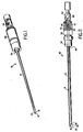
- a surgical device 10 eg. for arthroscopic surgery on the knee, includes a rigid, stationary outer tube 12, within which rotates a rigid inner tube 14 (shown partly in dotted lines in Figure 2), and a separate removable blade 16, also formed as a tube.
- the distal end of the outer tube 12 defines an opening 18 through which the blade 16 is exposed.
- Another opening 20 is defined in the blade 16.
- the sharpened edges 22 of the blade opening 20 co-operate with sharpened edges 24 of the outer tube opening 18 to shear tissue and bone during the operation of the device.
- the blade opening 20 aligns with the outer tube opening 18 periodically as the inner tube 14 rotates, thereby admitting tissue and bone fragments into the interior of the blade 16 and connected inner tube 14. These fragments are then removed by suction through a central opening 26 in the inner tube 14 as described later in connection with Figure 5.
- Device 10 further includes a hub 30 and a rotatable drive shaft 34.
- the proximal end of the outer tube 12 is rigidly mounted to the hub 30 at a sealed joint 36, while the proximal end of the inner tube 14 is mounted and sealed to the drive shaft 34, which rotates within the hub 30.
- the hub 30 and drive shaft 34 include short threaded portions 40 and 42 respectively, which after being engaged and screwed past each other, serve as abutments to prevent the drive shaft from sliding back out of the tube.
- a snap fit arrangement may be used instead of the threads to accomplish the same goal.
- the device 10 may be disposable or reusable.
- a disposable device designed for general purpose arthroscopic surgery will include an outer tube 12 and blade 16 made from stainless steel sufficiently hard to remove tissue of bone during operation of the device.
- the hub 30 and drive shaft 34 may be made of plastic, and the inner tube 14 may also be made of plastic since, as explained below in connection with Figures 3 and 4, the blade 16 need not be welded to the inner tube.
- Reusable devices will typically be made wholly of stainless steel.
- the blade 16 is sized relative to the outer tube opening 18 so that it cannot fall out of the opening.
- the distal end of the blade 16 abuts the distal, partially capped, end of the outer tube 12 and is radially restrained within the outer tube.
- the motor housing within a handpiece 50 presses axially on the drive shaft 34 to retain the connected inner tube 14 and blade 16 in close engagement with the outer tube 12.
- the clearance between the blade 16 and the outer tube 12, if desired, can be made less than that between the inner tube 14 and the outer tube so that the blade maintains a closer fit with the inner walls of the outer tube 12 and provides good cutting.
- This difference in clearance can be achieved by making the outer diameter of the outer diameter of the blade 16b greater than that of the inner tube 14, or by stepping down the diameter of the outer tube 12 towards its distal end.
- the inner tube 14 is a thin-walled tube having a series of circumferentially spaced portions 60 at its distal end, which engage with a corresponding series of portions 62 on the proximal end of the blade 16.
- the engaging portions 60 and 62 provide a loose attachment of the inner tube 14 and the blade 16 and transmit torque from the rotating inner tube to the blade without requiring a weld or other rigid attachment between the pieces.
- the loose attachment provides two degrees of freedom of motion between the tube 14 and the blade 16, one generally along the axis of rotation 64 of the blade, and one transverse to the axis.
- the corners of the engaging portions 60 and 62 are rounded to facilitate engagement of the inner tube 14 and the blade 16.
- the walls of the engaging portions 60 and 62 on the tube 14 and the blade 16 may be slightly sloped to further ease the engagement of the tube and the blade.
- Allowing play between the inner tube 14 and the blade 16, and providing a blade which is separate from the inner tube provides several advantages.
- the blade 16 movably adjusts so that it rotates in alignment with the outer tube 12, because the blade is not rigidly attached to the inner tube 14 and is free to move relative to the inner tube.
- the separate inner tube and blade feature not only eliminates the expense and effort of welding, straightening, and centreless grinding the two pieces, but also avoids disadvantages of previously known welded blades and inner tubes, eg. adhesive wear on the blade and seizure, encountered when the blade is undesirably joined off-centre or at an angle to the inner tube.
- the present invention allows a standard inner tube to be joined with any number of different blades; and tubes and blades made of materials that are difficult or impossible to weld or braze together, eg. ceramics, harder metals, and plastics, can nonetheless, be used together effectively.
- Figure 6 shows a particularly advantageous use of the invention in a surgical device 90 having a curved distal portion, eg. as described in pending patent application US Serial No. 477223, assigned to the assignee of the present invention.
- the device 90 has an outer tube 92, which is similar to the outer tube 12 described above in connection with Figures 1 to 5, except that the outer tube 92 is curved at a distal portion 92a so that it conforms with the curved portion 92a of the outer tube.
- Removably connected to the distal end of the inner tube 94 is a blade tip 96, similar to blade tip 16 described above in connection with Figures 1 to 5.
- the inner tube 94 can be made of a solid flexible plastic in the distal portion 94a, or can otherwise made flexible, instead of being slotted.
- an inner tube 100 similar to the inner tubes 14 and 94 described in connection with Figures 1 to 5 and Figure 6, can be formed of a solid plastic material flexible along its length so that if conforms to a curved portion 102a in an outer tube 102.
- Alternative embodiments include an inner tube slotted, or otherwise made flexible along its length, and further include surgical devices in which the outer tube itself is flexible, eg. so that it can be directed through a catheter arrangenent used during surgery on the back and hip regions of the body.
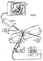
- the proximal end of the drive shaft 34 is fitted in a handpiece 50, which includes a motor (not shown) for rotating the drive shaft 34, inner tube 14, and blade tip 16 (shown in Figures 1 to 2).
- a handpiece 50 which includes a motor (not shown) for rotating the drive shaft 34, inner tube 14, and blade tip 16 (shown in Figures 1 to 2).
- a handpiece is described in US Patent No. 4705038.
- the device 10 is inserted onto the distal end of a handpiece 50 and then introduced through a puncture wound 70 into a knee joint 72, below the patella.
- Light is projected into the joint 72 through a second puncture wound 74 by a fibre optic light source 76.
- a visual image of the surgical site is then returned through a separate optical path to a television camera 76 and displayed on a television screen 80 for the surgeon to view. (Alternatively, the surgeon can view the image through an eyepiece, or the image can be recorded).
- the surgeon activates a motor (not shown) in the handpiece 50, which is connected to a power supply 56.
- the joint 72 is inflated with fluid introduced through a third puncture wound 82 by a fluid source 84.
- the fluid distends the joint 72, flushes blood out of the joint to given the surgeon a clear view of the area, and carries away any cut tissue.
- Viewing the image of the site on the television screen 80 the surgeon progressively cuts away the synovial tissue by moving the device 10 from side to side and axially. Tissue fragments cut by the device 10 and fluids are simultaneously withdrawn from the site through the opening 26 in the inner tube 14 in response to suction applied by a vacuum source 88.
- the device described above can have additional embodiments.
- many types of arthroscopic cutting elements can be used as an alternative to the blade shown and described, eg. as described in US Patent Nos. 4203444, 4274414, 4522206, 4662371, 4834729 and 4842578.
Abstract
Description
In a preferred aspect of the invention, the
Claims (30)
- A rotatable surgical device (10) comprising a rotatable drive element (34); a surgical element (16) with a removably connectable portion to said drive element (34) transmitting driving torque from said drive element (34) to said surgical element (16) and a retaining element (12) maintaining said drive (34) and surgical (16) elements in torque transmitting relation during operation of said device wherein said surgical element (16) is allowed at least one degree of freedom of motion relative to said drive element (34), wherein said surgical element (16) itself further comprises circumferentially spaced portions (62) arranged to engage with corresponding portions (60) of said drive element (34) so as to receive torque from said drive element (34), while permitting said surgical element (16) to be separated from said drive element (34) characterised in that said surgical element (16) during rotation has at least one degree of freedom of motion relative to said drive element (34) permitting said surgical element (16) to align itself relative to said retaining element (12) during rotation.
- A device (10) according to claim 1 wherein a degree of freedom is transverse to the axis of rotation of said surgical element (16) and said retaining element (12) surrounds said drive (34) and surgical elements (16) to limit said freedom of motion, while permitting said surgical element (16) to align itself relative to said retaining element (12) during rotation.
- A device (10) according to claim 1 or claim 2 wherein a degree of freedom is along the axis of rotation of said surgical element (16) and said retaining element (12) provides an abutment adjacent to said surgical element (16) to limit said freedom of motion.
- A device (10) according to claim 3 wherein said abutment is at the distal end of said surgical element (16).
- A device (10) according to any one of claims 1 to 4 wherein the retaining element (12) surrounds said drive (34) and surgical (16) elements to limit a transverse freedom of motion and provides an abutment adjacent to said surgical element (16) to limit a freedom of motion along the axis of rotation, while permitting said surgical element (16) to align itself relative to said retaining element (12) during rotation.
- A device (10) according to claim 5 wherein said retaining element (12) is a generally cylindrical tube (12) surrounding said drive (34) and surgical (16) elements, said tube (12) having a portion extending beyond the distal end of said surgical element (16) to provide said abutment.
- A device (10) of claim 6 wherein said drive element (34) is an elongated member rotatable within said tube (12), and said surgical element (16) is removably connectable to the distal end of said elongated member.
- A device (10) according to any one of claims 1 to 7 wherein said drive (34) and surgical (16) elements each have circumferentially spaced portions (60) arranged to engage to transmit torque from said drive element (34) to said surgical (16) element while permitting said drive (34) and surgical (16) elements to be separated.
- A device (10) according to any one of claims 1 to 8 including a passage means (26) to permit surgically removed bone or tissue to be withdrawn from said device through said passage means by suction.
- A device (10) according to claim 9 wherein said passage means (26) extends through the interior of said drive element (34) and said surgical element (16).
- A device (10) according to any one of claims 1 to 10 wherein said retaining element (12) and said surgical element (16) have edges arranged to interact to provide surgical cutting as said drive element (34) rotates.
- A device (10) according to any one of claims 1 to 11 wherein said retaining element (12) is a generally cylindrical tube surrounding said drive (34) and surgical (16) elements, wherein the clearance between said tube (12) and said surgical element (16) is less than the clearance between said tube (12) and said drive element (34).
- A device (10) according to claim 12 wherein said surgical element (16) has an outside diameter larger than that of said drive element (34), so that the clearance between said drive element (34) and said tube (12) is less than the clearance between said drive element (34) and said tube (12).
- A device (10) according to any one of claims 1 to 13 wherein said drive (34) and surgical (16) elements are of different materials.
- A device (10) according to claim 14 wherein said surgical element (16) is metal and said drive element (34) is a non-metal.
- A device (10) according to claim 14 wherein said materials are incompatible for welding or brazing.
- A device (10) according to any one of claims 1 to 16 wherein said drive element (34) has a curved portion.
- A device (10) according to any one of claims 1 to 17 wherein said drive element (34) has a flexible portion.
- A device (10) according to claim 18 wherein said drive element (34) is flexible along its entire length.
- A device (10) according to any of claims 17 to 19 wherein said retaining element (12) has a curved portion, (102a) and said flexible portion of said drive element (34) extends within and conforms to said curved portion.
- A device (10) according to any one of claims 6 to 20 wherein said drive element (34) is adapted to be retained within said tube.
- A device (10) according to claim 21 wherein the retaining element (12) and a proximal end of said drive element (34) each include an abutment for retaining said drive element (34) within said tube.
- A device (10) according to any one of claims 1 to 27 wherein said drive element (34) is constructed of plastic material.
- A surgical instrument comprising a handpiece (50) engaging the rotatable surgical device (10) as claimed in claim 1.
- An instrument according to claim 24 wherein said handpiece (50) contains a motor for rotating said drive element (34).
- An instrument according to claim 24 or claim 25 wherein said handpiece (50) includes a port connectable to a suction device.
- A rotatable surgical device (10) as claimed in claim 1 wherein the surgical element (16) is replaceable.
- A device (10) having an element (16) according to claim 27 wherein said portion of said surgical element (16) has two degrees of freedom relative to said drive element (34), one degree of freedom being transverse to the axis of rotation of said surgical element (16) and the other being along said axis.
- A device (10) having a surgical element (16) according to any one of claims 27 to 28 further comprising an interior passage arranged to communicate with a corresponding passage in said drive element (34) to permit surgically removed bone or tissue to be withdrawn through said passages by suction.
- A device (10) having an element (16) according to any one of claims 27 to 29 having edges arranged to interact with corresponding edges of said retaining element (12) to provide surgical cutting as said drive element (34) rotates.
Applications Claiming Priority (2)
| Application Number | Priority Date | Filing Date | Title |
|---|---|---|---|
| US60053190A | 1990-10-19 | 1990-10-19 | |
| US600531 | 1990-10-19 |
Publications (2)
| Publication Number | Publication Date |
|---|---|
| EP0481760A1 EP0481760A1 (en) | 1992-04-22 |
| EP0481760B1 true EP0481760B1 (en) | 1998-05-27 |
Family
ID=24403973
Family Applications (1)
| Application Number | Title | Priority Date | Filing Date |
|---|---|---|---|
| EP91309537A Expired - Lifetime EP0481760B1 (en) | 1990-10-19 | 1991-10-16 | Surgical device |
Country Status (9)
| Country | Link |
|---|---|
| US (1) | US5320635A (en) |
| EP (1) | EP0481760B1 (en) |
| JP (1) | JP3725180B2 (en) |
| AT (1) | ATE166558T1 (en) |
| AU (2) | AU650479B2 (en) |
| CA (1) | CA2053681C (en) |
| DE (1) | DE69129487T2 (en) |
| DK (1) | DK0481760T3 (en) |
| ES (1) | ES2118742T3 (en) |
Cited By (1)
| Publication number | Priority date | Publication date | Assignee | Title |
|---|---|---|---|---|
| WO2012059228A1 (en) | 2010-11-05 | 2012-05-10 | Hopp-Elektronik Gmbh & Co. Kg | Surgical instrument |
Families Citing this family (114)
| Publication number | Priority date | Publication date | Assignee | Title |
|---|---|---|---|---|
| US5368606A (en) * | 1992-07-02 | 1994-11-29 | Marlow Surgical Technologies, Inc. | Endoscopic instrument system |
| US5593416A (en) * | 1993-01-26 | 1997-01-14 | Donahue; John R. | Method of using flexible surgical instrument |
| US5620447A (en) * | 1993-01-29 | 1997-04-15 | Smith & Nephew Dyonics Inc. | Surgical instrument |
| US5833692A (en) * | 1993-01-29 | 1998-11-10 | Smith & Nephew, Inc. | Surgical instrument |
| ATE164992T1 (en) * | 1993-01-29 | 1998-05-15 | Smith & Nephew Inc | SWIVELING CURVED INSTRUMENT |
| AU682338B2 (en) * | 1993-05-06 | 1997-10-02 | Linvatec Corporation | Rotatable endoscopic shaver with polymeric blades |
| DE4323756A1 (en) * | 1993-07-15 | 1995-01-19 | Wolf Gmbh Richard | Surgical instrument for removing tissue |
| AU702754B2 (en) * | 1994-02-23 | 1999-03-04 | Smith & Nephew, Inc. | Surgical instrument |
| US5649547A (en) * | 1994-03-24 | 1997-07-22 | Biopsys Medical, Inc. | Methods and devices for automated biopsy and collection of soft tissue |
| ES2149315T3 (en) * | 1994-04-15 | 2000-11-01 | Smith & Nephew Inc | CURVED SURGICAL INSTRUMENT WITH SEGMENTED INTERIOR ELEMENT. |
| DE4422426C2 (en) * | 1994-06-28 | 1998-02-26 | Kurt Eberle Kg | Surgical instrument for removing tissue or cartilage |
| US5669921A (en) * | 1994-07-19 | 1997-09-23 | Linvatec Corporation | Endoscopic shaver blade window positioning system |
| EP0781114B1 (en) * | 1994-09-16 | 2005-05-25 | Ethicon Endo-Surgery, Inc. | Devices for defining and marking tissue |
| CA2203568A1 (en) * | 1994-10-24 | 1996-05-02 | Smith & Nephew Endoscopy, Inc. | Hollow surgical cutter with apertured flutes |
| US5593402A (en) * | 1994-11-14 | 1997-01-14 | Biosearch Medical Products Inc. | Laparoscopic device having a detachable distal tip |
| US5601583A (en) * | 1995-02-15 | 1997-02-11 | Smith & Nephew Endoscopy Inc. | Surgical instrument |
| US5766197A (en) * | 1995-04-14 | 1998-06-16 | Portlyn Corporation | Surgical cutting instrument with anti-torgue outer jacket |
| US5571129A (en) * | 1995-05-15 | 1996-11-05 | Portlyn Corporation | Surgical cutting instrument with improved cleaning capability and ease of use |
| US5690659A (en) * | 1995-06-02 | 1997-11-25 | Smith & Nephew, Inc. | Surgical cutting implement dispenser |
| US5618293A (en) * | 1995-06-06 | 1997-04-08 | Smith & Nephews Dyonics, Inc. | Surgical instrument |
| DE19530478A1 (en) * | 1995-08-18 | 1997-02-20 | Storz Karl Gmbh & Co | Medical instrument |
| USD381747S (en) * | 1996-01-02 | 1997-07-29 | Xomed Surgical Products, Inc. | Debrider instrument |
| US5695513A (en) * | 1996-03-01 | 1997-12-09 | Metagen, Llc | Flexible cutting tool and methods for its use |
| DE19619970A1 (en) * | 1996-05-17 | 1997-11-20 | Wolf Gmbh Richard | Endoscopic instrument |
| US6342061B1 (en) | 1996-09-13 | 2002-01-29 | Barry J. Kauker | Surgical tool with integrated channel for irrigation |
| US5792167A (en) * | 1996-09-13 | 1998-08-11 | Stryker Corporation | Surgical irrigation pump and tool system |
| US5851208A (en) * | 1996-10-15 | 1998-12-22 | Linvatec Corporation | Rotatable surgical burr |
| US5913867A (en) * | 1996-12-23 | 1999-06-22 | Smith & Nephew, Inc. | Surgical instrument |
| US5922003A (en) | 1997-05-09 | 1999-07-13 | Xomed Surgical Products, Inc. | Angled rotary tissue cutting instrument and method of fabricating the same |
| US5876416A (en) * | 1997-09-05 | 1999-03-02 | Hill; Frank C. | Surgical knife |
| US6171316B1 (en) | 1997-10-10 | 2001-01-09 | Origin Medsystems, Inc. | Endoscopic surgical instrument for rotational manipulation |
| US5964777A (en) * | 1997-12-11 | 1999-10-12 | Smith & Nephew, Inc. | Surgical cutting instrument |
| US6440138B1 (en) | 1998-04-06 | 2002-08-27 | Kyphon Inc. | Structures and methods for creating cavities in interior body regions |
| US6620180B1 (en) | 1998-09-09 | 2003-09-16 | Medtronic Xomed, Inc. | Powered laryngeal cutting blade |
| US20080146965A1 (en) | 2003-08-11 | 2008-06-19 | Salvatore Privitera | Surgical Device for The Collection of Soft Tissue |
| CA2287087C (en) | 1998-10-23 | 2007-12-04 | Ethicon Endo-Surgery, Inc. | Surgical device for the collection of soft tissue |
| US20010047183A1 (en) * | 2000-04-05 | 2001-11-29 | Salvatore Privitera | Surgical device for the collection of soft tissue |
| DE19850520B4 (en) * | 1998-11-03 | 2004-10-14 | Karl Storz Gmbh & Co. Kg | Medical instrument for removing tissue |
| US6120462A (en) * | 1999-03-31 | 2000-09-19 | Ethicon Endo-Surgery, Inc. | Control method for an automated surgical biopsy device |
| US6086544A (en) * | 1999-03-31 | 2000-07-11 | Ethicon Endo-Surgery, Inc. | Control apparatus for an automated surgical biopsy device |
| US6742236B1 (en) * | 1999-09-20 | 2004-06-01 | Smith & Nephew, Inc. | Making closed end tubes for surgical instruments |
| US6503263B2 (en) | 2000-09-24 | 2003-01-07 | Medtronic, Inc. | Surgical micro-shaving instrument with elevator tip |
| US6602203B2 (en) * | 2000-10-13 | 2003-08-05 | Ethicon Endo-Surgery, Inc. | Remote thumbwheel for a surgical biopsy device |
| US7244263B2 (en) | 2002-04-09 | 2007-07-17 | Stryker Corporation | Surgical instrument |
| US7549992B2 (en) * | 2002-12-20 | 2009-06-23 | Medtronic, Inc. | Surgical instrument with angled attachment |
| US7559927B2 (en) | 2002-12-20 | 2009-07-14 | Medtronic Xomed, Inc. | Surgical instrument with telescoping attachment |
| US20040193178A1 (en) | 2003-03-26 | 2004-09-30 | Cardiomind, Inc. | Multiple joint implant delivery systems for sequentially-controlled implant deployment |
| AU2004226464A1 (en) * | 2003-03-26 | 2004-10-14 | Cardiomind, Inc. | Implant delivery technologies |
| US7771463B2 (en) | 2003-03-26 | 2010-08-10 | Ton Dai T | Twist-down implant delivery technologies |
| US20040243163A1 (en) * | 2003-04-02 | 2004-12-02 | Gyrus Ent L.L.C | Surgical instrument |
| US7785337B2 (en) * | 2003-09-09 | 2010-08-31 | Medtronic Xomed, Inc. | Surgical micro-burring instrument and method of performing sinus surgery |
| US7651521B2 (en) * | 2004-03-02 | 2010-01-26 | Cardiomind, Inc. | Corewire actuated delivery system with fixed distal stent-carrying extension |
| US8932233B2 (en) | 2004-05-21 | 2015-01-13 | Devicor Medical Products, Inc. | MRI biopsy device |
| US9638770B2 (en) | 2004-05-21 | 2017-05-02 | Devicor Medical Products, Inc. | MRI biopsy apparatus incorporating an imageable penetrating portion |
| US7708751B2 (en) | 2004-05-21 | 2010-05-04 | Ethicon Endo-Surgery, Inc. | MRI biopsy device |
| US7905857B2 (en) | 2005-07-11 | 2011-03-15 | Covidien Ag | Needle assembly including obturator with safety reset |
| US7828773B2 (en) | 2005-07-11 | 2010-11-09 | Covidien Ag | Safety reset key and needle assembly |
| US7850650B2 (en) | 2005-07-11 | 2010-12-14 | Covidien Ag | Needle safety shield with reset |
| US20060276747A1 (en) | 2005-06-06 | 2006-12-07 | Sherwood Services Ag | Needle assembly with removable depth stop |
| US20060276772A1 (en) * | 2005-06-06 | 2006-12-07 | Sherwood Services Ag | Bayonet release of safety shield for needle tip |
| US7731692B2 (en) | 2005-07-11 | 2010-06-08 | Covidien Ag | Device for shielding a sharp tip of a cannula and method of using the same |
| US8123750B2 (en) * | 2005-08-17 | 2012-02-28 | Corespine Technologies, Llc | Apparatus and methods for removal of intervertebral disc tissues |
| US20070100414A1 (en) | 2005-11-02 | 2007-05-03 | Cardiomind, Inc. | Indirect-release electrolytic implant delivery systems |
| US7654735B2 (en) | 2005-11-03 | 2010-02-02 | Covidien Ag | Electronic thermometer |
| AU2007269189A1 (en) | 2006-06-30 | 2008-01-10 | Atheromed, Inc. | Atherectomy devices and methods |
| US8628549B2 (en) | 2006-06-30 | 2014-01-14 | Atheromed, Inc. | Atherectomy devices, systems, and methods |
| US9314263B2 (en) * | 2006-06-30 | 2016-04-19 | Atheromed, Inc. | Atherectomy devices, systems, and methods |
| US20080045986A1 (en) * | 2006-06-30 | 2008-02-21 | Atheromed, Inc. | Atherectomy devices and methods |
| US8361094B2 (en) * | 2006-06-30 | 2013-01-29 | Atheromed, Inc. | Atherectomy devices and methods |
| US20080004645A1 (en) * | 2006-06-30 | 2008-01-03 | Atheromed, Inc. | Atherectomy devices and methods |
| US20090018566A1 (en) | 2006-06-30 | 2009-01-15 | Artheromed, Inc. | Atherectomy devices, systems, and methods |
| US8007506B2 (en) * | 2006-06-30 | 2011-08-30 | Atheromed, Inc. | Atherectomy devices and methods |
| US20110112563A1 (en) * | 2006-06-30 | 2011-05-12 | Atheromed, Inc. | Atherectomy devices and methods |
| US9492192B2 (en) | 2006-06-30 | 2016-11-15 | Atheromed, Inc. | Atherectomy devices, systems, and methods |
| US8251916B2 (en) * | 2006-12-13 | 2012-08-28 | Devicor Medical Products, Inc. | Revolving tissue sample holder for biopsy device |
| US20140039343A1 (en) | 2006-12-13 | 2014-02-06 | Devicor Medical Products, Inc. | Biopsy system |
| US20130324882A1 (en) | 2012-05-30 | 2013-12-05 | Devicor Medical Products, Inc. | Control for biopsy device |
| US7981049B2 (en) * | 2006-12-13 | 2011-07-19 | Devicor Medical Products, Inc. | Engagement interface for biopsy system vacuum module |
| US9345457B2 (en) | 2006-12-13 | 2016-05-24 | Devicor Medical Products, Inc. | Presentation of biopsy sample by biopsy device |
| US7938786B2 (en) * | 2006-12-13 | 2011-05-10 | Devicor Medical Products, Inc. | Vacuum timing algorithm for biopsy device |
| US8702623B2 (en) * | 2008-12-18 | 2014-04-22 | Devicor Medical Products, Inc. | Biopsy device with discrete tissue chambers |
| US8480595B2 (en) * | 2006-12-13 | 2013-07-09 | Devicor Medical Products, Inc. | Biopsy device with motorized needle cocking |
| US8202229B2 (en) * | 2007-10-01 | 2012-06-19 | Suros Surgical Systems, Inc. | Surgical device |
| US8808200B2 (en) | 2007-10-01 | 2014-08-19 | Suros Surgical Systems, Inc. | Surgical device and method of using same |
| US8070762B2 (en) | 2007-10-22 | 2011-12-06 | Atheromed Inc. | Atherectomy devices and methods |
| US8236016B2 (en) | 2007-10-22 | 2012-08-07 | Atheromed, Inc. | Atherectomy devices and methods |
| US8357104B2 (en) * | 2007-11-01 | 2013-01-22 | Coviden Lp | Active stylet safety shield |
| US20090131819A1 (en) * | 2007-11-20 | 2009-05-21 | Ritchie Paul G | User Interface On Biopsy Device |
| US8052616B2 (en) * | 2007-11-20 | 2011-11-08 | Devicor Medical Products, Inc. | Biopsy device with fine pitch drive train |
| US8454531B2 (en) | 2007-11-20 | 2013-06-04 | Devicor Medical Products, Inc. | Icon-based user interface on biopsy system control module |
| US7858038B2 (en) * | 2007-11-20 | 2010-12-28 | Devicor Medical Products, Inc. | Biopsy device with illuminated tissue holder |
| US20090131821A1 (en) * | 2007-11-20 | 2009-05-21 | Speeg Trevor W V | Graphical User Interface For Biopsy System Control Module |
| US7806835B2 (en) * | 2007-11-20 | 2010-10-05 | Devicor Medical Products, Inc. | Biopsy device with sharps reduction feature |
| US9039634B2 (en) * | 2007-11-20 | 2015-05-26 | Devicor Medical Products, Inc. | Biopsy device tissue sample holder rotation control |
| US8657870B2 (en) | 2009-06-26 | 2014-02-25 | Biosensors International Group, Ltd. | Implant delivery apparatus and methods with electrolytic release |
| CA2713309C (en) | 2009-08-20 | 2013-07-02 | Howmedica Osteonics Corp. | Flexible acl instrumentation, kit and method |
| US9168084B2 (en) * | 2010-05-11 | 2015-10-27 | Electromedical Associates, Llc | Brazed electrosurgical device |
| US9308013B2 (en) | 2010-11-03 | 2016-04-12 | Gyrus Ent, L.L.C. | Surgical tool with sheath |
| US8574254B2 (en) | 2011-01-25 | 2013-11-05 | Smith & Nephew, Inc. | Arthroscopic cutting blade |
| CN103957825B (en) | 2011-10-13 | 2018-12-07 | 阿瑟罗迈德公司 | Atherectomy device, system and method |
| US9314295B2 (en) | 2011-10-20 | 2016-04-19 | Covidien Lp | Dissection scissors on surgical device |
| US9492221B2 (en) | 2011-10-20 | 2016-11-15 | Covidien Lp | Dissection scissors on surgical device |
| US9204868B2 (en) | 2011-12-02 | 2015-12-08 | Interscope, Inc. | Methods and apparatus for removing material from within a mammalian cavity using an insertable endoscopic instrument |
| US8882680B2 (en) | 2011-12-02 | 2014-11-11 | Interscope, Inc. | Insertable endoscopic instrument for tissue removal |
| US11076840B2 (en) | 2011-12-02 | 2021-08-03 | Interscope, Inc. | Surgical console, specimen receiver, and insertable endoscopic instrument for tissue removal |
| US9808146B2 (en) * | 2011-12-02 | 2017-11-07 | Interscope, Inc. | Endoscopic tool for debriding and removing polyps |
| USD855802S1 (en) | 2011-12-23 | 2019-08-06 | Interscope, Inc. | Disposable tool |
| US9827004B2 (en) * | 2012-01-31 | 2017-11-28 | Globus Medical, Inc. | Surgical disc removal tool |
| US9757536B2 (en) * | 2012-07-17 | 2017-09-12 | Novartis Ag | Soft tip cannula |
| US9888954B2 (en) | 2012-08-10 | 2018-02-13 | Cook Medical Technologies Llc | Plasma resection electrode |
| USD782026S1 (en) * | 2015-08-04 | 2017-03-21 | Covidien Lp | Endoscope sheath with oblique tip |
| US10813654B2 (en) * | 2016-10-13 | 2020-10-27 | Mani, Inc. | Nose knife |
| KR102582852B1 (en) | 2017-07-25 | 2023-09-26 | 스트라이커 유러피언 오퍼레이션스 홀딩스 엘엘씨 | Irrigation sleeves for use in surgical systems |
| US11304723B1 (en) | 2020-12-17 | 2022-04-19 | Avantec Vascular Corporation | Atherectomy devices that are self-driving with controlled deflection |
Family Cites Families (63)
| Publication number | Priority date | Publication date | Assignee | Title |
|---|---|---|---|---|
| US745722A (en) * | 1902-10-09 | 1903-12-01 | Chester M Freeman | Dental tool. |
| GB1235321A (en) * | 1968-01-30 | 1971-06-09 | Nat Res Dev | Improvements in or relating to drills for clearing obstructions |
| US3618611A (en) * | 1969-03-05 | 1971-11-09 | Julius C Urban | Vacuum rotary dissector |
| US3734099A (en) * | 1971-04-07 | 1973-05-22 | H Bender | Powered surgical cutter |
| US3945375A (en) * | 1972-04-04 | 1976-03-23 | Surgical Design Corporation | Rotatable surgical instrument |
| US3847154A (en) * | 1972-09-22 | 1974-11-12 | Weck & Co Edward | Surgical drill with detachable hand-piece |
| US3837345A (en) * | 1973-08-31 | 1974-09-24 | A Matar | Venous valve snipper |
| US3937222A (en) * | 1973-11-09 | 1976-02-10 | Surgical Design Corporation | Surgical instrument employing cutter means |
| US4320762A (en) * | 1975-03-10 | 1982-03-23 | Bentov Itzhak E | Dilator |
| US4020847A (en) * | 1975-11-05 | 1977-05-03 | Clark Iii William T | Rotating cutter catheter |
| US4071029A (en) * | 1976-05-21 | 1978-01-31 | Stryker Corporation | Angle handpiece |
| US4167944A (en) * | 1977-06-27 | 1979-09-18 | Surgical Design Corp. | Rotatable surgical cutting instrument with improved cutter blade wear |
| US4167943A (en) * | 1977-06-27 | 1979-09-18 | Surgical Design Corp. | Blade type rotatable surgical cutting instrument with improved cutter blade wear |
| US4200106A (en) * | 1977-10-11 | 1980-04-29 | Dinkelkamp Henry T | Fixed arc cyclic ophthalmic surgical instrument |
| US4203444A (en) * | 1977-11-07 | 1980-05-20 | Dyonics, Inc. | Surgical instrument suitable for closed surgery such as of the knee |
| US4246902A (en) * | 1978-03-10 | 1981-01-27 | Miguel Martinez | Surgical cutting instrument |
| US4274414A (en) * | 1979-02-21 | 1981-06-23 | Dyonics, Inc. | Surgical instrument |
| DE2914455A1 (en) * | 1979-04-10 | 1980-10-23 | Maschf Augsburg Nuernberg Ag | DEVICE FOR PRODUCING A COLLECTION IN A BONE |
| US4265231A (en) * | 1979-04-30 | 1981-05-05 | Scheller Jr Arnold D | Curved drill attachment for bone drilling uses |
| GB2087239B (en) * | 1980-11-12 | 1984-12-12 | Wolf Gmbh Richard | Improvements in or relating to bone or cartilage cutters |
| US4436091A (en) * | 1981-03-20 | 1984-03-13 | Surgical Design Corporation | Surgical cutting instrument with release mechanism |
| US4517977A (en) * | 1981-07-24 | 1985-05-21 | Unisearch Limited | Co-axial tube surgical infusion/suction cutter tip |
| US4445509A (en) * | 1982-02-04 | 1984-05-01 | Auth David C | Method and apparatus for removal of enclosed abnormal deposits |
| US4512344A (en) * | 1982-05-12 | 1985-04-23 | Barber Forest C | Arthroscopic surgery dissecting apparatus |
| US4541423A (en) * | 1983-01-17 | 1985-09-17 | Barber Forest C | Drilling a curved hole |
| US4770174A (en) * | 1983-01-21 | 1988-09-13 | Brimfield Precision, Inc. | Rotary cutting scissors for surgery |
| US4522206A (en) * | 1983-01-26 | 1985-06-11 | Dyonics, Inc. | Surgical instrument |
| US4662371A (en) * | 1983-01-26 | 1987-05-05 | Whipple Terry L | Surgical instrument |
| US4497320A (en) * | 1983-02-14 | 1985-02-05 | Rudolph Beaver, Inc. | Surgical blade unit |
| US4603694A (en) * | 1983-03-08 | 1986-08-05 | Richards Medical Company | Arthroscopic shaver |
| JPS59200644A (en) * | 1983-04-27 | 1984-11-14 | オリンパス光学工業株式会社 | Surgical incision instrument |
| US4589412A (en) * | 1984-01-03 | 1986-05-20 | Intravascular Surgical Instruments, Inc. | Method and apparatus for surgically removing remote deposits |
| US4631052A (en) * | 1984-01-03 | 1986-12-23 | Intravascular Surgical Instruments, Inc. | Method and apparatus for surgically removing remote deposits |
| US4598710A (en) * | 1984-01-20 | 1986-07-08 | Urban Engineering Company, Inc. | Surgical instrument and method of making same |
| US4672965A (en) * | 1984-08-16 | 1987-06-16 | Gilbert Baum | Surgical apparatus |
| US4706659A (en) * | 1984-12-05 | 1987-11-17 | Regents Of The University Of Michigan | Flexible connecting shaft for intramedullary reamer |
| US4649919A (en) * | 1985-01-23 | 1987-03-17 | Precision Surgical Instruments, Inc. | Surgical instrument |
| US4705038A (en) * | 1985-01-23 | 1987-11-10 | Dyonics, Inc. | Surgical system for powered instruments |
| US4756309A (en) * | 1985-02-14 | 1988-07-12 | Sachse Hans Ernst | Endoscope for removal of tissue |
| GB8516167D0 (en) * | 1985-06-26 | 1985-07-31 | Finsbury Instr Ltd | Surgical tool |
| US4681106A (en) * | 1985-08-12 | 1987-07-21 | Intravascular Surgical Instruments, Inc. | Catheter based surgical methods and apparatus therefor |
| US4733665C2 (en) * | 1985-11-07 | 2002-01-29 | Expandable Grafts Partnership | Expandable intraluminal graft and method and apparatus for implanting an expandable intraluminal graft |
| US4646738A (en) * | 1985-12-05 | 1987-03-03 | Concept, Inc. | Rotary surgical tool |
| US4723545A (en) * | 1986-02-03 | 1988-02-09 | Graduate Hospital Foundation Research Corporation | Power assisted arthroscopic surgical device |
| US4842578A (en) * | 1986-03-12 | 1989-06-27 | Dyonics, Inc. | Surgical abrading instrument |
| US4696667A (en) * | 1986-03-20 | 1987-09-29 | Helmut Masch | Intravascular catheter and method |
| US4690140A (en) * | 1986-04-01 | 1987-09-01 | John Mecca | Arterial regenerator |
| US4834729A (en) * | 1986-12-30 | 1989-05-30 | Dyonics, Inc. | Arthroscopic surgical instrument |
| US4983179A (en) * | 1986-12-30 | 1991-01-08 | Smith & Nephew Dyonics Inc. | Arthroscopic surgical instrument |
| US4790312A (en) * | 1987-01-20 | 1988-12-13 | Becton Dickinson Acutecare, Inc. | Surgical knife |
| US4850354A (en) * | 1987-08-13 | 1989-07-25 | Baxter Travenol Laboratories, Inc. | Surgical cutting instrument |
| US4844064A (en) * | 1987-09-30 | 1989-07-04 | Baxter Travenol Laboratories, Inc. | Surgical cutting instrument with end and side openings |
| DE3828478C2 (en) * | 1987-10-30 | 1994-05-05 | Olympus Optical Co | Surgical resection device |
| DE3906301A1 (en) * | 1988-04-28 | 1989-12-14 | Olympus Optical Co | Surgical resection instrument |
| US4867155A (en) * | 1988-06-21 | 1989-09-19 | Nu-Tech Industries, Inc. | Arthroscopic cutting device |
| FR2636225B1 (en) * | 1988-09-23 | 1990-12-14 | Inst Glaznykh Boleznei | MICROSURGICAL SCISSORS |
| US4923441A (en) * | 1989-02-23 | 1990-05-08 | Concept, Inc. | Surgical cutting instrument with titanium nitride coating on an inner tubular member |
| US5100426A (en) * | 1989-07-26 | 1992-03-31 | Fts Engineering, Inc. | Catheter for performing an atherectomy procedure |
| US5112299A (en) * | 1989-10-25 | 1992-05-12 | Hall Surgical Division Of Zimmer, Inc. | Arthroscopic surgical apparatus and method |
| US5047008A (en) * | 1989-10-27 | 1991-09-10 | Storz Instrument Company | Vitrectomy probe |
| US5152744A (en) * | 1990-02-07 | 1992-10-06 | Smith & Nephew Dyonics | Surgical instrument |
| US5114399A (en) * | 1990-10-01 | 1992-05-19 | Intramed Laboratories | Surgical device |
| CA2095821A1 (en) * | 1990-11-09 | 1992-05-10 | Arthur H. Hamlin | Surgical instrument for material removal |
-
1991
- 1991-10-16 AU AU85855/91A patent/AU650479B2/en not_active Ceased
- 1991-10-16 ES ES91309537T patent/ES2118742T3/en not_active Expired - Lifetime
- 1991-10-16 DK DK91309537T patent/DK0481760T3/en active
- 1991-10-16 DE DE69129487T patent/DE69129487T2/en not_active Expired - Fee Related
- 1991-10-16 EP EP91309537A patent/EP0481760B1/en not_active Expired - Lifetime
- 1991-10-16 AT AT91309537T patent/ATE166558T1/en not_active IP Right Cessation
- 1991-10-17 JP JP26961191A patent/JP3725180B2/en not_active Expired - Fee Related
- 1991-10-18 CA CA002053681A patent/CA2053681C/en not_active Expired - Fee Related
-
1992
- 1992-11-17 US US07/978,178 patent/US5320635A/en not_active Expired - Lifetime
-
1994
- 1994-09-22 AU AU74123/94A patent/AU674993B2/en not_active Ceased
Cited By (2)
| Publication number | Priority date | Publication date | Assignee | Title |
|---|---|---|---|---|
| WO2012059228A1 (en) | 2010-11-05 | 2012-05-10 | Hopp-Elektronik Gmbh & Co. Kg | Surgical instrument |
| DE102010050352A1 (en) | 2010-11-05 | 2012-05-10 | Hopp-Elektronik Gmbh & Co. Kg | Surgical instrument |
Also Published As
| Publication number | Publication date |
|---|---|
| US5320635A (en) | 1994-06-14 |
| JP3725180B2 (en) | 2005-12-07 |
| EP0481760A1 (en) | 1992-04-22 |
| ATE166558T1 (en) | 1998-06-15 |
| CA2053681C (en) | 2003-04-15 |
| DE69129487D1 (en) | 1998-07-02 |
| AU650479B2 (en) | 1994-06-23 |
| DE69129487T2 (en) | 1999-01-07 |
| DK0481760T3 (en) | 1999-03-22 |
| AU7412394A (en) | 1994-12-01 |
| JPH04269952A (en) | 1992-09-25 |
| CA2053681A1 (en) | 1992-04-20 |
| AU674993B2 (en) | 1997-01-16 |
| AU8585591A (en) | 1992-04-30 |
| ES2118742T3 (en) | 1998-10-01 |
Similar Documents
| Publication | Publication Date | Title |
|---|---|---|
| EP0481760B1 (en) | Surgical device | |
| US5618293A (en) | Surgical instrument | |
| EP0609084B1 (en) | Powered rotatable curved instrument | |
| US6053923A (en) | Method and apparatus for abrading tissue | |
| US5849023A (en) | Disposable remote flexible drive cutting apparatus | |
| EP2564795B1 (en) | Surgical tissue shavers | |
| US5620447A (en) | Surgical instrument | |
| AU690435B2 (en) | Surgical instrument | |
| EP1017323B9 (en) | Steerable surgical instrument | |
| US5947990A (en) | Endoscopic surgical instrument | |
| CA1175725A (en) | Surgical instrument for arthroscopic arthroplasty | |
| EP1702573B1 (en) | Endoscopic rotary abrader | |
| US11701137B2 (en) | Reusable blade hub assembly | |
| JP2000508206A (en) | Surgical equipment | |
| WO2003022162A1 (en) | Flexible inner tubular member and rotary tissue cutting instrument having flexible inner tubular member | |
| AU2002329752A1 (en) | Flexible inner tubular member and rotary tissue cutting instrument having flexible inner tubular member | |
| EP0669105B1 (en) | Endoscopic resection instrument |
Legal Events
| Date | Code | Title | Description |
|---|---|---|---|
| PUAI | Public reference made under article 153(3) epc to a published international application that has entered the european phase |
Free format text: ORIGINAL CODE: 0009012 |
|
| 17P | Request for examination filed |
Effective date: 19911031 |
|
| AK | Designated contracting states |
Kind code of ref document: A1 Designated state(s): AT BE CH DE DK ES FR GB IT LI NL SE |
|
| 17Q | First examination report despatched |
Effective date: 19940421 |
|
| RAP1 | Party data changed (applicant data changed or rights of an application transferred) |
Owner name: SMITH & NEPHEW ENDOSCOPY, INC. |
|
| RAP1 | Party data changed (applicant data changed or rights of an application transferred) |
Owner name: SMITH & NEPHEW, INC. |
|
| GRAG | Despatch of communication of intention to grant |
Free format text: ORIGINAL CODE: EPIDOS AGRA |
|
| GRAG | Despatch of communication of intention to grant |
Free format text: ORIGINAL CODE: EPIDOS AGRA |
|
| GRAH | Despatch of communication of intention to grant a patent |
Free format text: ORIGINAL CODE: EPIDOS IGRA |
|
| GRAH | Despatch of communication of intention to grant a patent |
Free format text: ORIGINAL CODE: EPIDOS IGRA |
|
| GRAA | (expected) grant |
Free format text: ORIGINAL CODE: 0009210 |
|
| AK | Designated contracting states |
Kind code of ref document: B1 Designated state(s): AT BE CH DE DK ES FR GB IT LI NL SE |
|
| REF | Corresponds to: |
Ref document number: 166558 Country of ref document: AT Date of ref document: 19980615 Kind code of ref document: T |
|
| REG | Reference to a national code |
Ref country code: CH Ref legal event code: EP |
|
| REF | Corresponds to: |
Ref document number: 69129487 Country of ref document: DE Date of ref document: 19980702 |
|
| ITF | It: translation for a ep patent filed |
Owner name: BARZANO' E ZANARDO ROMA S.P.A. |
|
| REG | Reference to a national code |
Ref country code: GB Ref legal event code: 711B |
|
| REG | Reference to a national code |
Ref country code: CH Ref legal event code: NV Representative=s name: BOVARD AG PATENTANWAELTE |
|
| ET | Fr: translation filed | ||
| REG | Reference to a national code |
Ref country code: ES Ref legal event code: FG2A Ref document number: 2118742 Country of ref document: ES Kind code of ref document: T3 |
|
| REG | Reference to a national code |
Ref country code: GB Ref legal event code: 711Z |
|
| REG | Reference to a national code |
Ref country code: GB Ref legal event code: 711H |
|
| REG | Reference to a national code |
Ref country code: DK Ref legal event code: T3 |
|
| PLBE | No opposition filed within time limit |
Free format text: ORIGINAL CODE: 0009261 |
|
| STAA | Information on the status of an ep patent application or granted ep patent |
Free format text: STATUS: NO OPPOSITION FILED WITHIN TIME LIMIT |
|
| 26N | No opposition filed | ||
| REG | Reference to a national code |
Ref country code: GB Ref legal event code: IF02 |
|
| PGFP | Annual fee paid to national office [announced via postgrant information from national office to epo] |
Ref country code: SE Payment date: 20021004 Year of fee payment: 12 |
|
| PGFP | Annual fee paid to national office [announced via postgrant information from national office to epo] |
Ref country code: DK Payment date: 20021014 Year of fee payment: 12 |
|
| PGFP | Annual fee paid to national office [announced via postgrant information from national office to epo] |
Ref country code: NL Payment date: 20021031 Year of fee payment: 12 Ref country code: ES Payment date: 20021031 Year of fee payment: 12 |
|
| PGFP | Annual fee paid to national office [announced via postgrant information from national office to epo] |
Ref country code: BE Payment date: 20021219 Year of fee payment: 12 |
|
| PGFP | Annual fee paid to national office [announced via postgrant information from national office to epo] |
Ref country code: AT Payment date: 20031013 Year of fee payment: 13 |
|
| PGFP | Annual fee paid to national office [announced via postgrant information from national office to epo] |
Ref country code: GB Payment date: 20031016 Year of fee payment: 13 |
|
| PG25 | Lapsed in a contracting state [announced via postgrant information from national office to epo] |
Ref country code: SE Free format text: LAPSE BECAUSE OF NON-PAYMENT OF DUE FEES Effective date: 20031017 Ref country code: ES Free format text: LAPSE BECAUSE OF NON-PAYMENT OF DUE FEES Effective date: 20031017 |
|
| PGFP | Annual fee paid to national office [announced via postgrant information from national office to epo] |
Ref country code: CH Payment date: 20031017 Year of fee payment: 13 |
|
| PG25 | Lapsed in a contracting state [announced via postgrant information from national office to epo] |
Ref country code: BE Free format text: LAPSE BECAUSE OF NON-PAYMENT OF DUE FEES Effective date: 20031031 |
|
| BERE | Be: lapsed |
Owner name: *SMITH & NEPHEW INC. Effective date: 20031031 |
|
| PG25 | Lapsed in a contracting state [announced via postgrant information from national office to epo] |
Ref country code: DK Free format text: LAPSE BECAUSE OF NON-PAYMENT OF DUE FEES Effective date: 20040430 |
|
| PG25 | Lapsed in a contracting state [announced via postgrant information from national office to epo] |
Ref country code: NL Free format text: LAPSE BECAUSE OF NON-PAYMENT OF DUE FEES Effective date: 20040501 |
|
| EUG | Se: european patent has lapsed | ||
| REG | Reference to a national code |
Ref country code: DK Ref legal event code: EBP |
|
| NLV4 | Nl: lapsed or anulled due to non-payment of the annual fee |
Effective date: 20040501 |
|
| PGFP | Annual fee paid to national office [announced via postgrant information from national office to epo] |
Ref country code: FR Payment date: 20041008 Year of fee payment: 14 |
|
| PG25 | Lapsed in a contracting state [announced via postgrant information from national office to epo] |
Ref country code: GB Free format text: LAPSE BECAUSE OF NON-PAYMENT OF DUE FEES Effective date: 20041016 Ref country code: AT Free format text: LAPSE BECAUSE OF NON-PAYMENT OF DUE FEES Effective date: 20041016 |
|
| PG25 | Lapsed in a contracting state [announced via postgrant information from national office to epo] |
Ref country code: LI Free format text: LAPSE BECAUSE OF NON-PAYMENT OF DUE FEES Effective date: 20041031 Ref country code: CH Free format text: LAPSE BECAUSE OF NON-PAYMENT OF DUE FEES Effective date: 20041031 |
|
| REG | Reference to a national code |
Ref country code: ES Ref legal event code: FD2A Effective date: 20031017 |
|
| GBPC | Gb: european patent ceased through non-payment of renewal fee |
Effective date: 20041016 |
|
| REG | Reference to a national code |
Ref country code: CH Ref legal event code: PL |
|
| PGFP | Annual fee paid to national office [announced via postgrant information from national office to epo] |
Ref country code: DE Payment date: 20051014 Year of fee payment: 15 |
|
| PG25 | Lapsed in a contracting state [announced via postgrant information from national office to epo] |
Ref country code: IT Free format text: LAPSE BECAUSE OF NON-PAYMENT OF DUE FEES Effective date: 20051016 |
|
| PG25 | Lapsed in a contracting state [announced via postgrant information from national office to epo] |
Ref country code: FR Free format text: LAPSE BECAUSE OF NON-PAYMENT OF DUE FEES Effective date: 20060630 |
|
| REG | Reference to a national code |
Ref country code: FR Ref legal event code: ST Effective date: 20060630 |
|
| PG25 | Lapsed in a contracting state [announced via postgrant information from national office to epo] |
Ref country code: DE Free format text: LAPSE BECAUSE OF NON-PAYMENT OF DUE FEES Effective date: 20070501 |