EP0483790B1 - Switching system of optical transmission lines for protecting from trouble - Google Patents
Switching system of optical transmission lines for protecting from trouble Download PDFInfo
- Publication number
- EP0483790B1 EP0483790B1 EP91118501A EP91118501A EP0483790B1 EP 0483790 B1 EP0483790 B1 EP 0483790B1 EP 91118501 A EP91118501 A EP 91118501A EP 91118501 A EP91118501 A EP 91118501A EP 0483790 B1 EP0483790 B1 EP 0483790B1
- Authority
- EP
- European Patent Office
- Prior art keywords
- optical
- terminal equipment
- port
- unidirectional
- bidirectional
- Prior art date
- Legal status (The legal status is an assumption and is not a legal conclusion. Google has not performed a legal analysis and makes no representation as to the accuracy of the status listed.)
- Expired - Lifetime
Links
Images


Classifications
-
- H—ELECTRICITY
- H04—ELECTRIC COMMUNICATION TECHNIQUE
- H04J—MULTIPLEX COMMUNICATION
- H04J14/00—Optical multiplex systems
- H04J14/02—Wavelength-division multiplex systems
- H04J14/0287—Protection in WDM systems
- H04J14/0293—Optical channel protection
- H04J14/0295—Shared protection at the optical channel (1:1, n:m)
-
- H—ELECTRICITY
- H04—ELECTRIC COMMUNICATION TECHNIQUE
- H04B—TRANSMISSION
- H04B10/00—Transmission systems employing electromagnetic waves other than radio-waves, e.g. infrared, visible or ultraviolet light, or employing corpuscular radiation, e.g. quantum communication
- H04B10/03—Arrangements for fault recovery
- H04B10/032—Arrangements for fault recovery using working and protection systems
-
- H—ELECTRICITY
- H04—ELECTRIC COMMUNICATION TECHNIQUE
- H04J—MULTIPLEX COMMUNICATION
- H04J14/00—Optical multiplex systems
- H04J14/02—Wavelength-division multiplex systems
- H04J14/0287—Protection in WDM systems
- H04J14/0289—Optical multiplex section protection
- H04J14/0291—Shared protection at the optical multiplex section (1:1, n:m)
-
- H—ELECTRICITY
- H04—ELECTRIC COMMUNICATION TECHNIQUE
- H04J—MULTIPLEX COMMUNICATION
- H04J14/00—Optical multiplex systems
- H04J14/02—Wavelength-division multiplex systems
- H04J14/0278—WDM optical network architectures
- H04J14/0279—WDM point-to-point architectures
Definitions
- the present invention relates to a switching system of optical transmission lines in an optical communication system for protecting a communication between terminal stations.
- the switching system according to the present invention is applied to an optical communication system comprising at least one working transmission line and a protection transmission line.
- Figure 1 is a diagram showing a conventional construction of an optical communication system comprising two terminal stations and a plurality of working optical transmission lines and a protection (stand-by) optical transmission line provided between the terminal stations.
- reference numeral 910, 911, ⁇ 91N each denote a multiplexer/demultiplexer in a terminal station A
- 920 denotes a protection switch in the terminal station A
- 910', 911', ⁇ 91N' each denote a multiplexer/demultiplexer in a terminal station B
- 920' denotes a protection switch in the terminal station B
- L 0 denotes a protection transmission line
- L 1 , L 2 , ⁇ L N each denote a working transmission line
- TS1, TS2, ⁇ TSN and TS1', TS2', ⁇ TSN' each denote a group of transmission lines of tributary signals of low transmission rates
- LPS and LPS' each denote a group of transmission lines for transmitting tribu
- the protection switches 920 in the terminal station A are provided on the sides of groups TS1, TS2, ⁇ TSN of transmission lines of tributary signals of low transmission rates, with regard to the multiplexer/demultiplexers 910, 911, ⁇ 91N, and 910', 911', ⁇ 91N', and connects the groups TS1, TS2, ⁇ TSN of transmission lines transmitting tributary signals of low transmission rates to the corresponding multiplexer/demultiplexers 911, ⁇ 91N, respectively in a normal condition.
- the respective groups TS1, TS2, ⁇ TSN of tributary signals which are to be transmitted from the terminal station A to the terminal station B are multiplexed in the corresponding multiplexer/demultiplexers 911, ⁇ 91N to electric signals of high transmission rates. Then, the electric signals of high transmission rates which are generated in the respective multiplexer/demultiplexers 911, ⁇ 91N, are converted to optical signals in E/O (electric signal to optical signal) conversion circuits (not shown) provided on the sides of the optical transmission lines L 1 , L 2 , ⁇ L N , to be transmitted through the optical transmission lines to the terminal stations B.
- E/O electric signal to optical signal
- optical signals transmitted through the optical transmission lines L 1 , L 2 , ⁇ L N are respectively converted to electric signals in O/E (optical signal to electric signal) conversion circuits (not shown) provided on the sides of the optical transmission lines L 1 , L 2 , ⁇ L N of the corresponding multiplexer/demultiplexers 911, ⁇ 91N, and are then respectively demultiplexed in the corresponding multiplexer/demultiplexers 911, ⁇ 91N to tributary signals to be transmitted through the groups TS1, TS2, ⁇ TSN of transmission lines transmitting tributary signals of low transmission rates. Similar signal transmission and reception operations are performed in the terminal station B.
- O/E optical signal to electric signal
- the transmission lines transmitting tributary signals of low transmission rates corresponding to the above transmission line of the trouble are connected to the multiplexer/demultiplexer 910 so that the tributary signals to be transmitted from the terminal station A to the terminal station B are multiplexed in the multiplexer/demultiplexer 910 to an electric signal of a high transmission rate.
- the tributary signals of the low priorities from the above group LPS of transmission lines are multiplexed and transmitted through the protection transmission line L 0 , the tributary signals of low priorities are discarded in this case.
- the electric signal of a high transmission rate is converted to optical signals in an E/O conversion circuit (not shown) which is provided on the side of the optical transmission lines L 0 , to be transmitted through the optical transmission lines to the terminal stations B.
- optical signals transmitted through the optical transmission lines L 0 are converted to electric signals in an O/E conversion circuit (not shown) provided on the side of the optical transmission lines L 0 of the multiplexer/demultiplexer 910.
- the electric signal is demultiplexed in the multiplexer/demultiplexer 910 to tributary signals of low transmission rate which are to be transmitted through the above transmission lines transmitting tributary signals of low transmission rates, corresponding to the above transmission line of the trouble. Similar signal transmission and reception operations are performed in the terminal station B.
- the switching operation from the working transmission line to the protection transmission line is carried out on the side of the tributary signals (of the low transmission rates). Therefore, the switching operations must be carried out for a large number of transmission lines transmitting tributary signals of low transmission rates. Since, in practice, the respective pieces of terminal equipment corresponding to the plurality of optical transmission lines are provided in different locations in a rack or shelf of an apparatus in a terminal station, a large number of cables must be provided for connecting between these pieces of terminal equipment for the above switching operation, and therefore, the hardware construction becomes large and very complicated, as shown in Fig. 1, thereby increasing a cost, and decreasing reliability of the system.
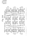
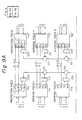
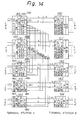
- FIG. 2 As an attempt to solve the above problem, a construction as shown in Fig. 2 is provided.
- reference numeral 930, 931, ⁇ 93N each denote a multiplexer/demultiplexer in a terminal station A, 940, 941, ⁇ 94N, and 960, 961, ⁇ 96N each denote a parallel to serial and serial to parallel conversion circuit in a terminal station A
- 950 denotes a protection switch in the terminal station A
- 970, 971
- ⁇ 97N each denote an E/O and O/E conversion circuit in a terminal station A
- 930', 931', ⁇ 93N' each denote a multiplexer/demultiplexer in a terminal station B, 940', 941', ⁇ 94N', and 960', 961', ⁇ 96N' each denote a parallel to serial and serial to parallel conversion circuit
- 950' denotes a protection switch in the terminal station B, 970
- the protection switches 950 and 950' are each provided on the side of electric signals of the high transmission rates, with regard to the multiplexer/demultiplexers 930, 931, ⁇ 93N, or 930', 931', ⁇ 93N'.
- the electric signals may have to be propagated for a relatively long distance from a position of a corresponding working transmission line to the protection transmission line when the electric signal is transmitted through the protection transmission line as shown in Fig. 1, it is difficult to carry out the switching operation at the stage of the electric signals of the high transmission rates which are respectively equal to the transmission rates of the corresponding optical transmission lines L 1 , L 2 , ⁇ L N .
- the parallel to serial and serial to parallel conversion circuits 940, 941, ⁇ 94N, 960, 961, ⁇ 96N, 940', 941', ⁇ 94N', and 960', 961', ⁇ 96N' are provided on both sides of the respective protection switches 950 and 950' so that the above electric signals of the high transmission rates are respectively divided into a plurality of parallel electric signals by the parallel to serial and serial to parallel conversion circuits 940, 941, ⁇ 94N, and 940', 941', ⁇ 94N', and the switching to the protection transmission line L 0 is carried out in the stage of the divided parallel electric signals.
- the tributary signals transmitted from the above groups TS1, TS2, ⁇ TSN and TS1', TS2', ⁇ TSN' of transmission lines are first multiplexed in the corresponding multiplexer/demultiplexers 930, 931, ⁇ 93N, or 930', 931', ⁇ 93N', and are then divided into a plurality of parallel electric signals by the parallel to serial and serial to parallel conversion circuits 940, 941, ⁇ 94N, and 940', 941', ⁇ 94N'.
- the protection switches 950 and 950' each connect the transmission lines transmitting tributary signals of low transmission rates corresponding to the above trouble transmission line, to the parallel to serial and serial to parallel conversion circuits 960 and 960', and connect the other transmission lines transmitting tributary signals of low transmission rates corresponding to the other transmission lines in which no trouble occurs, to the corresponding parallel to serial and serial to parallel conversion circuits 961, ⁇ 96N, and 961', ⁇ 96N'.
- the outputs of the protection switches 950 and 950' are converted into the above-mentioned electric signals of high transmission rates, and the electric signals are converted to optical signals in the corresponding E/O and O/E conversion circuits 970', 971', ⁇ 97N', 970', 971', ⁇ 97N' to be transmitted through the respective optical transmission lines L 0 , L 1 , L 2 , ⁇ L N .
- the optical signals are converted to electric signals of the high transmission rates in the corresponding E/O and O/E conversion circuits 970', 971', ⁇ 97N', 970', 971', ⁇ 97N', and then the electric signals are divided into a plurality of parallel electric signals in the corresponding parallel to serial and serial to parallel conversion circuits 960, 961, ⁇ 96N, and 960', 961', ⁇ 96N'.
- the divided electric signals are supplied to the protection switches 950 and 950'.
- the outputs of the protection switches 950 and 950' are converted into the above-mentioned electric signals of high transmission rates in the parallel to serial and serial to parallel conversion circuits 940, 941, ⁇ 94N, and 940', 941', ⁇ 94N', and the electric signals are demultiplexed to tributary signals of low transmission rates to transmit the tributary signals through the transmission lines of the low transmission rates.
- FR-A-2 598 573 discusses a structure for ensuring a signal transmission in an optical fiber, in which a number of normal paths and a number of safety paths is provided. Matrix commutators switch a signal from a normal path to a safety path in the event of failure in the normal path. Even though the normal paths and safety paths are optical paths, the re-routing of signals does not involve optical communication paths.
- the object of the present invention is to provide a better switching system of optical transmission lines in an optical communication system for protecting a communication between terminal stations, which is constructed with simpler hardware of smaller size to reduce cost, and improve reliability of the system.
- Figure 3 is a diagram showing a construction of first and second embodiments of the present invention.
- reference numeral 100 denotes a protection piece of optical terminal equipment in a terminal station A
- 100' denotes a protection piece of optical terminal equipment in a terminal station B
- 100, 101, ⁇ 10N, 100', 101', ⁇ 10N' each denote a working piece of optical terminal equipment in the terminal station A
- 200, 201, ⁇ 20N each denote an optical coupler in the terminal station A
- 200', 201', ⁇ 20N' each denote an optical coupler in the terminal station B.
- 300 and 300' each denote a bidirectional optical coupler
- 300 and 300' each denote a bidirectional optical switch.
- TX denotes an optical signal transmitting unit
- RX denotes an optical signal receiving unit.
- L 0 denotes a protection transmission line
- L 1 , L 2 , ⁇ L N each denote a working transmission line
- TS1, TS2, ⁇ TSN and TS1', TS2', ⁇ TSN' each denote a group of transmission lines of tributary signals of low transmission rates
- LPS and LPS' each denote a group of transmission lines for transmitting tributary signals of low priorities, where each of the transmission lines are assumed to be a bidirectional transmission line, as in the constructions of Figs. 1 and 2.
- Figure 4 is a diagram showing a construction of each of the protection pieces of optical terminal equipment 100 and 100' and the working pieces of optical terminal equipment 101, ⁇ 10N, and 101', ⁇ 10N'.
- reference numeral 161 denotes an interface circuit for transmitting and receiving a plurality of tributary signals through a plurality of ports
- 162 denotes a multiplexer/demultiplexer for multiplexing tributary signals to an electric signal of a high transmission rate, and demultiplexing an electric signal to a plurality of tributary signals of relatively low transmission rates
- 163 denotes a switch unit
- 164 denotes the optical signal transmitting unit TX connected to the protection transmission line L 0
- 165 denotes the optical signal receiving unit RX connected to the protection transmission line L 0
- 166 denotes the optical signal transmitting unit TX connected to a corresponding one of the optical couplers 200, 201, ⁇ 20N each denote an optical coupler in the terminal station A, and
- each of the protection pieces of optical terminal equipment 100 and 100' and the working piece of optical terminal equipment 101, ⁇ 10N, and 101', ⁇ 10N' comprises two sets of optical signal transmitting units TX and optical signal receiving unit RX, where one set of optical signal transmitting unit TX and optical signal receiving units RX is connected to a corresponding one of the bidirectional optical transmission lines L 0 , L 1 , L 2 , ⁇ L N , and the other set is provided for connecting the protection piece of optical terminal equipment 100 or 100' with one of the working pieces of optical terminal equipment 101, ⁇ 10N, and 101', ⁇ 10N' through a bidirectional optical path as explained later.
- each of the optical signal transmitting units TX comprises an electric-to-optical converter for converting the above electric signal of relatively high transmission rate to an optical signal
- each of the optical signal receiving units RX comprises an optical-to-electric converter for converting an optical signal to an electric signal of high transmission rate.
- a pair of an unidirectional optical input port for receiving an optical signal and an unidirectional optical output port for transmitting an optical signal in each set constitute a bidirectional optical port.
- the construction of the switch unit 163 is different for the first and second embodiments, and is explained later.
- each of the above optical couplers 200, 201, ⁇ 20N and 200', 201', ⁇ 20N' comprises one bidirectional optical port and two unidirectional optical ports
- each of the optical couplers 300 and 300' comprises a coupled bidirectional optical port for transmitting and receiving coupled optical signals and a plurality of uncoupled bidirectional optical ports respectively for transmitting and receiving uncoupled optical signals.
- One of the two unidirectional optical ports of each of the above optical couplers 200, 201, ⁇ 20N and 200', 201', ⁇ 20N' receives an optical signal, and the received optical signal passes through the optical coupler to be output from the bidirectional optical port of the optical coupler.
- the bidirectional optical port thereof also receives an optical signal, and the received optical signal passes through the optical coupler to be output from the other of the two unidirectional optical ports of the optical coupler.
- One of the plurality of uncoupled bidirectional optical ports of each of the above optical couplers 300 and 300' receives an optical signal, and the received optical signal passes through the optical coupler to be output from the coupled bidirectional optical port of the optical coupler.
- the coupled bidirectional optical port thereof also receives an optical signal, and the received optical signal passes through the optical coupler to be output from all of the plurality of uncoupled bidirectional optical ports of the optical coupler.
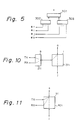
- the optical coupler as above is realized by a star coupler, or a tree connection of a plurality of optical switches as shown in Fig. 5.
- the optical couplers 200 and 200' are respectively provided corresponding to the protection pieces of optical terminal equipment 100 and 100', and the optical couplers 201, ⁇ 20N and 201', ⁇ 20N' are respectively provided corresponding to the working pieces of optical terminal equipment 101, ⁇ 10N and 101', ⁇ 10N'.
- the above two unidirectional optical ports of each of the optical couplers 200, 201, ⁇ 20N and 200', 201', ⁇ 20N' are respectively connected through bidirectional optical paths to the above optical input port and optical output port in the bidirectional optical port of the corresponding one of the protection piece of optical terminal equipment 100 and 100' and the working pieces of optical terminal equipment 101, ⁇ 10N and 101', ⁇ 10N'.
- the bidirectional optical port of each of the optical couplers 200 and 200' is connected through a bidirectional optical path to the coupled bidirectional optical port of the optical coupler 300 or 300' in each of the optical terminal stations A and B.
- the bidirectional optical port of each of the optical couplers 201, ⁇ 20N and 200', 201', ⁇ 20N' is connected to one of the plurality of uncoupled bidirectional optical ports of the corresponding one of the optical couplers 300 and 300'.
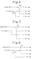
- Figure 6 shows a construction of the switch unit 163 in each working piece of optical terminal equipment 101, ⁇ 10N and 100', 101', ⁇ 10N' in the first embodiment of the present invention.
- reference numeral 168 and 169 each denote a connection switch.
- the connection switch 168 connects the output terminal of the multiplexer 162 to a selected one of the optical signal transmitting unit TX 164 and the optical signal transmitting unit TX 166
- the connection switch 169 in each working piece of optical terminal equipment connects a selected one of the output of the optical signal receiving unit 165 and the output of the optical signal receiving unit RX 167 to the input terminal of the demultiplexer 162.
- the above connections with the optical signal transmitting unit TX 166 and the optical signal receiving unit RX 167 are made in one of the working pieces of optical terminal equipment 101, ⁇ 10N and 101', ⁇ 10N' when the working piece of optical terminal equipment is connected to the protection transmission line.
- the output of the multiplexer 162 is connected through the connection switch 168 to the optical signal transmitting unit TX 164, and the output terminal of the optical signal receiving unit RX 165 is connected through the connection switch 169 to the input terminal of the demultiplexer 162 in the working pieces of optical terminal equipment.
- Figure 7 shows a construction of the switch unit 163 in each protection piece of optical terminal equipment 100 or 100' in the first embodiment of the present invention.
- reference numeral 170 denotes a connection switch.
- the connection switch 170 connects the input terminal of the optical signal transmitting unit TX 164 to a selected one of the output terminal of the multiplexer 162 and the output terminal of the optical signal receiving unit RX 167, and the output of the optical signal receiving unit RX 165 is supplied to both of the input terminal of the demultiplexer 162 and the input terminal of the optical signal transmitting unit TX 166.
- connection with the optical signal receiving unit RX 167 is made in the protection piece of optical terminal equipment 100 and 100' when one of the working pieces of optical terminal equipment is connected to the protection transmission line.
- the output of the multiplexer 162 is connected through the connection switch 170 to the optical signal transmitting unit TX 164.
- the multiplexed signal is converted to an optical signal in the optical signal transmitting unit 166, and then the optical signal is transmitted through one 20i of the optical couplers 201, ⁇ 20N corresponding to the working piece of optical terminal equipment 10i, the optical coupler 300, and the optical coupler 200, to the optical signal receiving unit RX 167 in the protection piece of optical terminal equipment 100.
- the optical signal is converted to an electric signal in the optical signal receiving unit RX 167, and the electric signal is supplied through the switch unit 170 to the optical signal receiving unit RX 164 to be transmitted through the protection transmission line L 0 .
- an optical signal transmitted through the protection transmission line L 0 is converted to an electric signal in the optical signal receiving unit RX 165, and the electric signal is supplied through the connection switch 171 to the optical signal transmitting unit TX 166.
- the optical signal transmitting unit TX 166 converts the electric signal to an optical signal.
- the optical signal is transmitted through the optical coupler 200, the optical coupler 300, and the optical coupler 20i to the optical signal receiving unit RX 167 in the working piece of optical terminal equipment 10i.
- transmission lines for the tributary signals TSi on the side of the optical terminal station A are connected through the working piece of optical terminal equipment 10i, the above bidirectional optical path between the working piece of optical terminal equipment 10i and the protection piece of optical terminal equipment 100, the protection piece of optical terminal equipment 100, the protection transmission line L 0 , the protection piece of optical terminal equipment 100' on the side of the optical terminal station B, a bidirectional optical path between the protection piece of optical terminal equipment 100' and a working piece of optical terminal equipment 10i', and the working piece of optical terminal equipment 100', to tributary signals TSi'.
- connection switches in the switch unit 163 are controlled by a control unit (not shown) provided in each optical terminal station, for realizing the above connection of one working piece of optical terminal equipment corresponding to a working transmission line having a trouble, with the protection transmission line L 0 .
- optical signals are transmitted to only one of the uncoupled bidirectional optical ports of each of the optical couplers 300 and 300' from the optical signal transmitting unit TX 166 of only one of the working pieces of optical terminal equipment in each optical terminal station, and optical signals transmitted from the optical signal transmitting unit TX 166 of the protection piece of optical terminal equipment 100 or 100' are always output from all of the uncoupled bidirectional optical ports of the optical coupler 300 or 300' in each optical terminal station, and therefore, are always applied to the optical signal receiving units RX 167 of all of the working pieces of optical terminal equipment 101, ⁇ 10N or 101', ⁇ 10N'.
- the optical coupler 300 may be replaced by two unidirectional optical couplers passing optical signals in different directions.
- the optical couplers 200, 201, 202, ⁇ 20N may be eliminated.
- the bidirectional optical signals transmitted between the protection piece of optical terminal equipment and the working pieces of optical terminal equipment may have different wavelengths.
- a filter circuit for extracting a required wavelength component may be provided between the optical couplers 201, 202, ⁇ 20N and the optical signal receiving unit of the corresponding working piece of optical terminal equipment.
- each of the optical switches 300 and 300' comprises a first-type bidirectional optical port for transmitting and receiving coupled optical signals and a plurality of second-type bidirectional optical ports each for exclusively transmitting and receiving optical signals.
- a selected one of the plurality of second-type bidirectional optical ports of each of the above optical switches 300 and 300' receives an optical signal, and the received optical signal passes through the optical switch to be output from the first-type bidirectional optical port of the optical switch.
- the first-type bidirectional optical port thereof also receives an optical signal, and the received optical signal passes through the optical switch to be output from a selected one of the plurality of second-type bidirectional optical ports of the optical switch.
- the bidirectional optical port of each of the optical couplers 200 and 200' is connected through a bidirectional optical path to the first-type bidirectional optical port of the optical switch 300 or 300' in each of the optical terminal stations A and B.
- the bidirectional optical port of each of the optical couplers 201, ⁇ 20N and 200', 201', ⁇ 20N' is connected to one of the plurality of second-type bidirectional optical ports of the corresponding one of the optical switches 300 and 300'.
- one of the second-type bidirectional optical ports connected to one of the working pieces of optical terminal equipment corresponding to a working transmission line having a trouble and to be connected to the protection transmission line L 0 is selected by a control unit (not shown).
- Figure 8 shows a construction of the switch unit 163 in each working piece of optical terminal equipment 101, ⁇ 10N and 100', 101', ⁇ 10N' in the second embodiment of the present invention.
- reference numeral 172 denotes a connection point and 173 denote a connection switch.
- the connection switch 168 connects a selected one of the output terminals of the optical signal receiving units RX 165 and 167 to the input terminal of the demultiplexer 162.
- the output of the demultiplexer 162 is supplied to both of the input terminals of the optical signal transmitting units TX 164 and 166.
- the above output of the optical signal receiving unit RX 167 is connected to the input terminal of the demultiplexer 162 in one of the working pieces of optical terminal equipment 101, ⁇ 10N and 101', ⁇ 10N' when the working piece of optical terminal equipment is connected to the protection transmission line L 0 .
- the output of the optical signal receiving unit RX 165 is connected to the input terminal of the demultiplexer 162.
- the construction of the switch unit 163 in the protection piece of optical terminal equipment in the second embodiment is the same as the first embodiment.
- connection switches in the switch unit 163 and the optical switch 300 or 300' are controlled by a control unit (not shown) provided in each optical terminal station, for realizing the above connection of one working piece of optical terminal equipment corresponding to a working transmission line having a trouble, with the protection transmission line L 0 .
- the operation of the construction of the second embodiment is the same as the above-mentioned first embodiment except that the optical switches 300 and 300' are provided instead of explained below, and the construction of the switch unit 163 is as shown in Fig. 8 instead of Fig. 6.
- the optical signals to be transmitted from each of the working pieces of optical terminal equipment are always output from both of the optical signal transmitting units TX 164 and 166 of each working piece of optical terminal equipment, and therefore, are always applied to a corresponding second-type bidirectional optical port of the optical switch 300 or 300', but the optical signals are output from only one of the plurality of second-type bidirectional optical ports to the optical signal receiving unit RX 167 of only one of the working piece of optical terminal equipment 101, ⁇ 10N or 101', ⁇ 10N' in each optical terminal station.
- the optical switch 300 may be replaced by two unidirectional optical switches passing optical signals in different directions.
- the optical couplers 200, 201, 202, ⁇ 20N may be eliminated.
- the bidirectional optical signals transmitted between the protection piece of optical terminal equipment and the working pieces of optical terminal equipment may have different wavelengths.
- a filter circuit for extracting a required wavelength component may be provided between the optical couplers 201, 202, ⁇ 20N and the optical signal receiving unit of the corresponding working piece of optical terminal equipment.
- Figure 9 is a diagram showing a construction for the third and fourth embodiments of the present invention.
- reference numeral 110 denotes a protection piece of optical terminal equipment in a terminal station A
- 110' denotes a protection piece of optical terminal equipment in a terminal station B
- 111, 112, ⁇ 11N, 111', 112', ⁇ 10N' each denote a working piece of optical terminal equipment in the terminal station A
- 210, 211, ⁇ 21N each denote an optical coupler in the terminal station A
- 210', 211', ⁇ 21N' each denote an optical coupler in the terminal station B.
- 311, ⁇ 31N and 311', ⁇ 31N' each denote a bidirectional optical coupler
- 311, ⁇ 31N and 311', ⁇ 31N' each denote a bidirectional optical switch
- ⁇ 11N', TX, RX, L 0 , L 1 , L 2 , ⁇ L N , TS1, TS2, ⁇ TSN, TS1', TS2', ⁇ TSN', LPS, and LPS' each denote the same element as in the constructions of Figs. 1, 2, and 3.
- Each of the protection pieces of optical terminal equipment 110 and 110' in the third and fourth embodiments has the same construction as the first and second embodiments (Figs. 4 and 7).
- Each of the working pieces of optical terminal equipment 111, ⁇ 11N, and 111', ⁇ 11N' in the third embodiment has the same construction as the first embodiment (Figs. 4 and 6), and each of the working pieces of optical terminal equipment 111, ⁇ 11N, and 111', ⁇ 11N' in the fourth embodiment has the same construction as the second embodiment (Figs. 4 and 8).
- each of the optical couplers 210, 211, ⁇ 21N, 210', 211', ⁇ 21N' has the same construction as the optical couplers 200, 201, ⁇ 20N, 200', 201', ⁇ 20N' in the construction of Fig. 4, and is connected to a corresponding one of the protection piece of optical terminal equipment 110 and 110' and the working pieces of optical terminal equipment 111, ⁇ 11N, and 111', ⁇ 11N' in the same manner as the construction of Fig. 4.
- the optical couplers 311, ⁇ 31N and 311', ⁇ 31N' are respectively provided corresponding to the optical couplers 211, ⁇ 21N and 211', ⁇ 21N'.
- Each of the optical couplers 311, ⁇ 31N and 311', ⁇ 31N' comprises a coupled bidirectional optical port for transmitting and receiving coupled optical signals and two uncoupled bidirectional optical ports respectively for transmitting and receiving uncoupled optical signals.
- One of the two uncoupled bidirectional optical ports of each of the above optical couplers 311, ⁇ 31N and 311', ⁇ 31N' receives an optical signal, and the received optical signal passes through the optical coupler to be output from the coupled bidirectional optical port of the optical coupler, as shown in Fig. 10.
- the coupled bidirectional optical port of the optical couplers 311, ⁇ 31N and 311', ⁇ 31N' also receives an optical signal, and the received optical signal passes through the optical coupler to be output from both of the two uncoupled bidirectional optical ports of the optical coupler, as shown in Fig. 10.
- the bidirectional optical port of each of the optical couplers 210 and 210' is connected through a bidirectional optical path to the coupled bidirectional optical port of the optical coupler 311 or 311' corresponding to working piece 111 of optical terminal equipment (which is located at a nearest location to the protection piece of optical terminal equipment 110 or 110') in each of the optical terminal stations A and B.
- the bidirectional optical port of each of the optical couplers 211, ⁇ 21N and 211', ⁇ 21N' is connected to one of the two uncoupled bidirectional optical ports of the corresponding one of the optical couplers 311, ⁇ 31N and 311', ⁇ 31N'.
- each optical coupler 21i or 21i' and a corresponding optical coupler 31i or 31i' is shown in Fig. 10.
- the coupling of optical signals in the construction of Fig. 10 is realized by the construction of Fig. 11.
- the multiplexed signal is converted to an optical signal in the optical signal transmitting unit 166, and then the optical signal is transmitted through the optical coupler 21i, the optical coupler 31i, the optical coupler 31i-1, ⁇ the optical coupler 311, and the optical coupler 210, to the optical signal receiving unit RX 167 in the protection piece of optical terminal equipment 110.
- the optical signal is converted to an electric signal in the optical signal receiving unit RX 167, and the electric signal is supplied through the switch unit 170 to the optical signal receiving unit RX 164 to be transmitted through the protection transmission line L 0 to the other optical terminal station.
- an optical signal transmitted through the protection transmission line L 0 is converted to an electric signal in the optical signal receiving unit RX 165, and the electric signal is supplied through the connection switch 171 to the optical signal transmitting unit TX 166.
- the optical signal transmitting unit TX 166 converts the electric signal to an optical signal.
- the optical signal is transmitted through the optical coupler 210, the optical coupler 311, ⁇ the optical coupler 31i-1, the optical coupler 31i, and the optical coupler 20i to the optical signal receiving unit RX 167 in the working piece of optical terminal equipment 11i.
- transmission lines for the tributary signals TSi on the side of the optical terminal station A are connected through the working piece of optical terminal equipment 11i, the above bidirectional optical path between the working piece of optical terminal equipment 11i and the protection piece of optical terminal equipment 110, the protection transmission line L 0 , the protection piece of optical terminal equipment 110' on the side of the optical terminal station B, a bidirectional optical path between the protection piece of optical terminal equipment 110' and a working piece of optical terminal equipment 10i', and the working piece of optical terminal equipment 110', to tributary signals TSi'.
- connection switches in the switch unit 163 are controlled by a control unit (not shown) provided in each optical terminal station, for realizing the above connection of one working piece of optical terminal equipment corresponding to a working transmission line having a trouble, with the protection transmission line L 0 .
- optical signals are transmitted to the protection piece of optical terminal equipment 110 or 110' from the optical signal transmitting unit TX 166 of only one of the working pieces of optical terminal equipment, and optical signals transmitted from the optical signal transmitting unit TX 166 of the protection piece of optical terminal equipment 110 or 110' always pass through all of the optical couplers 311, ⁇ 31N and 311', ⁇ 31N' in each optical terminal station, and therefore, are always applied to the optical signal receiving units RX 167 of all of the working pieces of optical terminal equipment 111, ⁇ 11N or 111', ⁇ 11N' in each optical terminal station.
- the optical switches 311, ⁇ 31N and 311', ⁇ 31N' are respectively provided corresponding to the optical couplers 211, ⁇ 21N and 211', ⁇ 21N'.
- Each of the optical switches 311, ⁇ 31N and 311', ⁇ 31N' comprises a first-type bidirectional optical port for transmitting and receiving optical signals and two second-type bidirectional optical ports each for exclusively transmitting and receiving second-type optical signals.
- a selected one of the two second-type bidirectional optical ports of each of the above optical couplers 311, ⁇ 31N and 311', ⁇ 31N' receives an optical signal, and the received optical signal passes through the optical coupler to be output from the first-type bidirectional optical port of the optical coupler.
- the first-type bidirectional optical port of the optical couplers 311, ⁇ 31N and 311', ⁇ 31N' also receives an optical signal, and the received optical signal passes through the optical coupler to be output from a selected one of the two second-type bidirectional optical ports of the optical coupler.
- the bidirectional optical port of each of the optical couplers 210 and 210' is connected through a bidirectional optical path to the first-type bidirectional optical port of the optical switch 311 or 311' corresponding to working piece 111 of optical terminal equipment (which is located at a nearest location to the protection piece of optical terminal equipment 110 or 110') in each of the optical terminal stations A and B.
- the bidirectional optical port of each of the optical couplers 211, ⁇ 21N and 211', ⁇ 21N' is connected to one of the two second-type bidirectional optical ports of the corresponding one of the optical switches 311, ⁇ 31N and 311', ⁇ 31N'.
- the multiplexed signal is converted to an optical signal in the optical signal transmitting unit 166, and then the optical signal is transmitted through the optical coupler 21i, the optical switch 31i, the optical switch 31i-1, ⁇ the optical switch 311, and the optical coupler 210, to the optical signal receiving unit RX 167 in the protection piece of optical terminal equipment 110.
- the optical signal is converted to an electric signal in the optical signal receiving unit RX 167, and the electric signal is supplied through the switch unit 170 to the optical signal receiving unit RX 164 to be transmitted through the protection transmission line L 0 to the other optical terminal station.
- an optical signal transmitted through the protection transmission line L 0 is converted to an electric signal in the optical signal receiving unit RX 165, and the electric signal is supplied through the connection switch 171 to the optical signal transmitting unit TX 166.
- the optical signal transmitting unit TX 166 converts the electric signal to an optical signal.
- the optical signal is transmitted through the optical coupler 210, the optical switch 311, ⁇ the optical switch 31i-1, the optical switch 31i, and the optical coupler 21i to the optical signal receiving unit RX 167 in the working piece of optical terminal equipment 11i.
- transmission lines for the tributary signals TSi on the side of the optical terminal station A are connected through the working piece of optical terminal equipment 11i, the above bidirectional optical path between the working piece of optical terminal equipment 11i and the protection piece of optical terminal equipment 110, the protection piece of optical terminal equipment 110, the protection transmission line L 0 , the protection piece of optical terminal equipment 110' on the side of the optical terminal station B, a bidirectional optical path between the protection piece of optical terminal equipment 100' and a working piece of optical terminal equipment 11i', and the working piece of optical terminal equipment 110', to tributary signals TSi'.
- connection switches in the switch unit 163 and the optical switches 311, ⁇ 31N and 311', ⁇ 31N' are controlled by a control unit (not shown) provided in each optical terminal station, for realizing the above connection of one working piece of optical terminal equipment corresponding to a working transmission line having a trouble, with the protection transmission line L 0 .
- the operation of the construction of the fourth embodiment is the same as the above-mentioned third embodiment except that the optical switches 300 and 300' are provided instead of explained below, and the construction of switch unit 163 is as shown in Fig. 8 instead of Fig. 6.
- the optical signals which are to be transmitted from each of the working pieces of optical terminal equipment are always output from both of the optical signal transmitting units TX 164 and 166, and therefore, are always applied to the second-type bidirectional optical port of the corresponding optical switch 31i or 31i' in each optical terminal station, and the optical signals output from the protection piece of optical terminal equipment 110 or 110' reach the optical signal receiving unit RX 167 of only one of the working pieces of optical terminal equipment 111, ⁇ 11N or 111', ⁇ 11N' in each optical terminal station.
- Figure 12 is a diagram showing a construction for the fifth, sixth, and seventh embodiments of the present invention.
- reference numeral 500 denotes a control unit
- 120 denotes a protection piece of optical terminal equipment in a terminal station A
- 120' denotes a protection piece of optical terminal equipment in a terminal station B
- 121, 122, ⁇ 12N, 121', 122', ⁇ 12N' each denote a working piece of optical terminal equipment in the terminal station A.
- Reference numeral 321, ⁇ 32N and 321', ⁇ 32N' each denote an unidirectional optical switch in the fifth embodiment, and denote an optical switch in the sixth and seventh embodiments.
- Reference numeral 331, ⁇ 33N and 331', ⁇ 33N' each denote an optical switch in the fifth and seventh embodiments, and denote an optical switch in the sixth embodiment.
- ⁇ 12N', TX, RX, L 0 , L 1 , L 2 , ⁇ L N , TS1, TS2, ⁇ TSN, TS1', TS2', ⁇ TSN', LPS, and LPS' each denote the same element as in the constructions of Figs. 1, 2, 3, and 9.
- Each of the protection pieces of optical terminal equipment 120 and 120' in the third and fourth embodiments has the same construction as the first, second, third, fourth embodiments (Figs. 4, 7, and 9).
- Each of the working pieces of optical terminal equipment 121, ⁇ 12N, and 121', ⁇ 12N' in the fifth embodiment has the same construction as the first and third embodiments (Figs. 4 and 6), and each of the working pieces of optical terminal equipment 121, ⁇ 12N, and 121', ⁇ 12N' in the sixth and seventh embodiments has the same construction as the second and fourth embodiments (Figs. 4, 8, and 9).
- the unidirectional optical couplers 321, ⁇ 32N and 321', ⁇ 32N' are respectively provided corresponding to the working pieces of optical terminal equipment 121, ⁇ 12N, and 121', ⁇ 12N'.
- Each of the optical couplers 321, ⁇ 32N and 321', ⁇ 32N' comprises a coupled unidirectional optical port for transmitting coupled optical signals and two uncoupled unidirectional optical ports respectively for receiving uncoupled optical signals.
- One of the two uncoupled unidirectional optical ports of each of the above optical couplers 321, ⁇ 32N and 321', ⁇ 32N' receives an optical signal, and the received optical signal passes through the optical coupler to be output from the coupled unidirectional optical port of the optical coupler.
- the unidirectional optical couplers 331, ⁇ 33N and 331', ⁇ 33N' are respectively provided corresponding to the working pieces of optical terminal equipment 121, ⁇ 12N, and 121', ⁇ 12N'.
- Each of the optical couplers 331, ⁇ 33N and 331', ⁇ 33N' comprises a coupled unidirectional optical port for receiving coupled optical signals and two uncoupled unidirectional optical ports respectively for transmitting uncoupled optical signals.
- the coupled unidirectional optical ports of each of the above optical couplers 331, ⁇ 33N and 331', ⁇ 33N' receives an optical signal, and the received optical signal passes through the optical coupler to be output from both of the uncoupled unidirectional optical ports of the optical coupler.
- the optical input port of the optical signal receiving unit 167 of the protection piece of optical terminal equipment 120 or 120' is connected through an unidirectional optical path to the coupled unidirectional optical port of the optical coupler 321 or 321' corresponding to working piece 121 of optical terminal equipment (which is located at a nearest location to the protection piece of optical terminal equipment 120 or 120'), and the optical output port of the optical signal transmitting unit 166 of the protection piece of optical terminal equipment 120 or 120' is connected through an unidirectional optical path to the coupled unidirectional optical port of the optical coupler 331 or 331' corresponding to working piece 121 of optical terminal equipment, in each of the optical terminal stations A and B.
- the optical output port of the optical signal transmitting unit 166 of each working piece of optical terminal equipment 121, ⁇ 12N, and 121', ⁇ 12N' is connected to one of the two uncoupled unidirectional optical ports of the corresponding one of the optical couplers 321, ⁇ 32N and 321', ⁇ 32N', and the optical input port of the optical signal receiving unit 167 of each working piece of optical terminal equipment 121, ⁇ 12N, and 121', ⁇ 12N' is connected to one of the two uncoupled unidirectional optical ports of the corresponding one of the optical couplers 331, ⁇ 33N and 331', ⁇ 33N'.
- the multiplexed signal is converted to an optical signal in the optical signal transmitting unit 166, and then the optical signal is transmitted through the optical coupler 32i, the optical coupler 32i-1, ⁇ the optical coupler 321 to the optical signal receiving unit RX 167 in the protection piece of optical terminal equipment 120.
- the optical signal is converted to an electric signal in the optical signal receiving unit RX 167, and the electric signal is supplied through the switch unit 170 to the optical signal receiving unit RX 164 to be transmitted through the protection transmission line L 0 to the other optical terminal station.
- an optical signal transmitted through the protection transmission line L 0 is converted to an electric signal in the optical signal receiving unit RX 165, and the electric signal is supplied through the connection switch 171 to the optical signal transmitting unit TX 166.
- the optical signal transmitting unit TX 166 converts the electric signal to an optical signal.
- the optical signal is transmitted through the optical coupler 331, ⁇ the optical coupler 33i-1, the optical coupler 33i to the optical signal receiving unit RX 167 in the working piece of optical terminal equipment 12i.
- transmission lines for the tributary signals TSi on the side of the optical terminal station A are connected through the working piece of optical terminal equipment 12i, the above unidirectional optical path between the working piece of optical terminal equipment 12i and the protection piece of optical terminal equipment 120, the protection piece of optical terminal equipment 120, the protection transmission line L 0 , the protection piece of optical terminal equipment 120' on the side of the optical terminal station B, a unidirectional optical path between the protection piece of optical terminal equipment 120' and a working piece of optical terminal equipment 12i', and the working piece of optical terminal equipment 120', to tributary signals TSi'.
- connection switches in the switch unit 163 are controlled by the control unit 500 or 500' provided in each optical terminal station for realizing the above connection of one working piece of optical terminal equipment corresponding to a working transmission line having a trouble, to the protection transmission line L 0 .
- optical signals are transmitted to the protection piece of optical terminal equipment 110 or 110' from the optical signal transmitting unit TX 166 of only one of the working pieces of optical terminal equipment in each optical terminal station, and optical signals transmitted from the optical signal transmitting unit TX 166 of the protection piece of optical terminal equipment 110 or 110' always pass through all of the optical couplers 331, ⁇ 33N and 331', ⁇ 33N' in each optical terminal station, and therefore, are always applied to the optical signal receiving units RX 167 of all of the working pieces of optical terminal equipment 121, ⁇ 12N or 121', ⁇ 12N' in each optical terminal station.
- the reference numerals 321, ⁇ 32N and 321', ⁇ 32N' each denote an unidirectional optical switch
- the optical switches 321, ⁇ 32N and 321', ⁇ 32N' are respectively provided corresponding to the working pieces of optical terminal equipment 121, ⁇ 12N, and 121', ⁇ 12N'.
- Each of the optical switches 321, ⁇ 32N and 321', ⁇ 32N' comprises a first-type unidirectional optical port for transmitting optical signals and two second-type unidirectional optical ports each for exclusively receiving optical signals.
- a selected one of the two second-type unidirectional optical ports of each of the above optical switches 321, ⁇ 32N and 321', ⁇ 32N' receives an optical signal, and the received optical signal passes through the optical switch to be output from the first-type unidirectional optical port of the optical switch.
- the unidirectional optical switches 331, ⁇ 33N and 331', ⁇ 33N' are respectively provided corresponding to the working pieces of optical terminal equipment 121, ⁇ 12N, and 121', ⁇ 12N'.
- Each of the optical switches 331, ⁇ 33N and 331', ⁇ 33N' comprises a first-type unidirectional optical port for receiving optical signals and two second-type unidirectional optical ports each for exclusively transmitting optical signals.
- the first-type unidirectional optical ports of each of the above optical switches 331, ⁇ 33N and 331', ⁇ 33N' receives an optical signal, and the received optical signal passes through the optical switch to be output from a selected one of the second-type unidirectional optical ports of the optical switch.
- the optical input port of the optical signal receiving unit 167 of the protection piece of optical terminal equipment 120 or 120' is connected through an unidirectional optical path to the first-type unidirectional optical port of the optical switch 321 or 321' corresponding to working piece 121 of optical terminal equipment (which is located at a nearest location to the protection piece of optical terminal equipment 120 or 120'), and the optical output port of the optical signal transmitting unit 166 of the protection piece of optical terminal equipment 120 or 120' is connected through an unidirectional optical path to the first-type unidirectional optical port of the optical switch 331 or 331' corresponding to working piece 121 of optical terminal equipment, in each of the optical terminal stations A and B.
- the optical output port of the optical signal transmitting unit 166 of each working piece of optical terminal equipment 121, ⁇ 12N, and 121', ⁇ 12N' is connected to one of the two second-type unidirectional optical ports of the corresponding one of the optical switches, 321, ⁇ 32N and 321', ⁇ 32N', and the optical input port of the optical signal receiving unit 167 of each working piece of optical terminal equipment 121, ⁇ 12N, and 121', ⁇ 12N' is connected to one of the two second-type unidirectional optical ports of the corresponding one of the optical switches 331, ⁇ 33N and 331', ⁇ 33N'.
- the multiplexed signal is converted to an optical signal in the optical signal transmitting unit 166, and then the optical signal is transmitted through the optical switch 32i, the optical switch 32i-1, ⁇ the optical switch 321 to the optical signal receiving unit RX 167 in the protection piece of optical terminal equipment 120.
- the optical signal is converted to an electric signal in the optical signal receiving unit RX 167, and the electric signal is supplied through the switch unit 170 to the optical signal receiving unit RX 164 to be transmitted through the protection transmission line L 0 to the other optical terminal station.
- an optical signal transmitted through the protection transmission line L 0 is converted to an electric signal in the optical signal receiving unit RX 165, and the electric signal is supplied through the connection switch 171 to the optical signal transmitting unit TX 166.
- the optical signal transmitting unit TX 166 converts the electric signal to an optical signal.
- the optical signal is transmitted through the optical switch 331, ⁇ the optical switch 33i-1, the optical switch 33i to the optical signal receiving unit RX 167 in the working piece of optical terminal equipment 12i.
- transmission lines for the tributary signals TSi on the side of the optical terminal station A are connected through the working piece of optical terminal equipment 12i, the above two unidirectional optical paths between the working piece of optical terminal equipment 12i and the protection piece of optical terminal equipment 120, the protection piece of optical terminal equipment 120, the protection transmission line L 0 , the protection piece of optical terminal equipment 120' on the side of the optical terminal station B, two unidirectional optical paths between the protection piece of optical terminal equipment 120' and a working piece of optical terminal equipment 12i', and the working piece of optical terminal equipment 120', to tributary signals TSi'.
- connection switches in the switch unit 163 and the optical switches 321, ⁇ 32N and 321', ⁇ 32N', and 331, ⁇ 33N and 331', ⁇ 33N' are controlled by the control unit 500 or 500' provided in each optical terminal station, for realizing the above connection of one working piece of optical terminal equipment corresponding to a working transmission line having a trouble, with the protection transmission line L 0 .
- optical signals are transmitted to the protection piece of optical terminal equipment 110 or 110' from the optical signal transmitting unit TX 166 of only one of the working pieces of optical terminal equipment in each optical terminal station, and optical signals transmitted from the optical signal transmitting unit TX 166 of the protection piece of optical terminal equipment 110 or 110' reach the optical signal receiving unit RX 167 of only one of the working pieces of optical terminal equipment 121, ⁇ 12N, and 121', ⁇ 12N' in each optical terminal station.
- the optical signal transmitting unit TX 164 and 166 in each working piece of optical terminal equipment is in operation (in an ON state).
- the optical signal transmitting unit TX 166 in each working piece of optical terminal equipment is in an OFF state in a normal condition in the first, third, and fifth embodiments, and begins to operate when the working piece of optical terminal equipment is switched to the protection transmission line.
- the optical signal transmitting unit contains an automatic power control (APC) circuit for maintaining a power of the output of the optical signal transmitting unit constant, and it takes a considerable time (rising time) for the automatic power control circuit to shift its state from the OFF state to a stable ON state. Therefore, some data may be lost during the rising time when a working piece of optical terminal equipment is switched from a normal working transmission line Li to the protection transmission line L 0 .
- APC automatic power control
- the optical signal receiving unit RX 165 and 167 in each working piece of optical terminal equipment is in operation (in an ON state).
- the optical signal receiving unit RX 167 in each working piece of optical terminal equipment is in an OFF state in a normal condition in the second, fourth, and sixth embodiments, and begins to operate when the working piece of optical terminal equipment is switched to the protection transmission line.
- the optical signal receiving unit contains an automatic gain control (AGC) circuit for maintaining a power of the output of the optical signal receiving unit constant, and it takes a considerable time (rising time) for the automatic gain control circuit to shift its state from the OFF state to a stable ON state. Therefore, some data may be lost during the rising time when a working piece of optical terminal equipment is switched from a normal working transmission line Li to the protection transmission line L 0 .
- AGC automatic gain control
- the seventh embodiment of the present invention is provided.
- optical switches 321, ⁇ 32N and 321', ⁇ 32N' are respectively provided corresponding to the working pieces of optical terminal equipment 121, ⁇ 12N, and 121', ⁇ 12N'.
- Each of the optical switches 321, ⁇ 32N and 321', ⁇ 32N' has the same construction as the corresponding element in the construction of the sixth embodiment, and is connected to the protection piece of optical terminal equipment, the corresponding working piece of optical terminal equipment, and the other optical switches 321, ⁇ 32N and 321', ⁇ 32N' in the same manner as in the construction of the sixth embodiment.
- the seventh embodiment in the construction of Fig.
- unidirectional optical couplers 331, ⁇ 33N and 331', ⁇ 33N' are respectively provided corresponding to the working pieces of optical terminal equipment 121, ⁇ 12N, and 121', ⁇ 12N'.
- Each of the optical couplers 331, ⁇ 33N and 331', ⁇ 33N' has the same construction as the corresponding element in the construction of the sixth embodiment, and is connected to the protection piece of optical terminal equipment, the corresponding working piece of optical terminal equipment, and the other optical switches 331, ⁇ 33N and 331', ⁇ 33N' in the same manner as in the construction of the fifth embodiment.
- optical signals are transmitted from a working piece of optical terminal equipment to be connected to the protection transmission line, to the protection piece of optical terminal equipment in the same manner as the sixth embodiment, and optical signals are transmitted from the protection piece of optical terminal equipment to the working piece of optical terminal equipment to be connected to the protection transmission line, in the same manner as the fifth embodiment.
- the optical signal transmitting unit TX 166 and the optical signal receiving unit RX 167 in each working piece of optical terminal equipment are constantly in the ON state, and therefore, the above problems in the first to sixth embodiments are solved in the seventh embodiment.
- the bidirectional optical coupler or optical switch 300 may be replaced by an unidirectional optical switch for transmitting an optical signal in a direction from the working pieces of optical terminal equipment to the protection piece of optical terminal equipment, and an unidirectional optical coupler for transmitting an optical signal in the other direction from the protection piece of optical terminal equipment to the working pieces of optical terminal equipment.
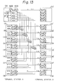
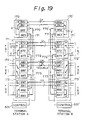
- Figure 13 is a diagram showing a construction for the eighth embodiments of of the present invention.
- reference numeral 130 and 130' each denote a protection piece of optical terminal equipment
- 131, ⁇ 138, and 131' each denote a working piece of optical terminal equipment
- L 0 denotes a protection transmission line
- C1, C2, ⁇ C8 each denote an unidirectional optical coupler or optical switch
- 600 to 620 each denote a pair of the above-mentioned optical signal transmitting unit and optical signal receiving unit, which are also denoted by "E/O & O/E" in Fig.
- 621 denotes a switch unit
- 622 denotes a multiplexer/demultiplexer.
- paths of optical signals between the protection piece of optical terminal equipment 130 and the working pieces of optical terminal equipment 131, ⁇ 138 in the optical terminal station A are shown, and paths of optical signals between the protection piece of optical terminal equipment 130' and the working pieces of optical terminal equipment 131', ⁇ 138' in the optical terminal station B are not shown in Fig. 13, the same construction as in the optical terminal station A is provided in the optical terminal station B.
- the transmission rate of the protection transmission line L 0 is four times the transmission rate of each of the working transmission lines L 1 , L 2 , ⁇ L 8 .
- the protection piece 130 or 130' of optical terminal equipment in each optical terminal station comprises a plurality (four) of pairs of optical signal transmitting units and optical signal receiving units 601 to 604 other than the pair of optical signal transmitting unit and optical signal receiving unit 600 which are connected to the protection transmission line L 0 , where the plurality of pairs of optical signal transmitting units and optical signal receiving units 601 to 604 are respectively correspond to, and connected to two of the working transmission lines L 1 , L 2 , ⁇ L 8 .
- the transmission of optical signals between the pair of the optical signal transmitting unit and the optical signal receiving unit 601 of the protection piece of optical terminal equipment 130, and the pair of units 606 of the working piece of optical terminal equipment 131 or the pair of units 614 of the working piece of optical terminal equipment 135, through the unidirectional optical couplers or optical switches C1 and C2, is carried out in the same manner as in one of the fifth to seventh embodiments.
- the transmissions of optical signals are carried out: between the pair of the optical signal transmitting unit and the optical signal receiving units 602 of the protection piece of optical terminal equipment 130, and the pair of units 608 of the working piece of optical terminal equipment 132 or the pair of units 616 of the working piece of optical terminal equipment 136, through the unidirectional optical couplers or optical switches C3 and C4; between the pair of the optical signal transmitting unit and the optical signal receiving units 603 of the protection piece of optical terminal equipment 130, and the pair of units 610 of the working piece of optical terminal equipment 133 or the pair of units 616 of the working piece of optical terminal equipment 137, through the unidirectional optical couplers or optical switches C5 and C6; and between the pair of the optical signal transmitting unit and the optical signal receiving units 604 of the protection piece of optical terminal equipment 130, and the pair of units 612 of the working piece of optical terminal equipment 134 or the pair of units 618 of the working piece of optical terminal equipment 138, through the unidirectional optical couplers or optical switches C7 and C
- the optical signals transmitted from the working pieces of optical terminal equipment are respectively converted to electric signals in the optical signal receiving units in the corresponding pairs of units 601 to 604 in the protection piece of optical terminal equipment 130, and then, the electric signals are supplied to the multiplexer 622 through the switch unit 621.
- the electric signals are multiplexed in the multiplexer 622, and then, the multiplexed electric signal is converted to an optical signal in the optical signal transmitting unit in the pair 600 to be transmitted through the protection transmission line L 0 .
- an optical signal transmitted through the protection transmission line L 0 is converted to an electric signal in the optical signal receiving unit in the pair of units 600, and then, the electric signal is demultiplexed in the demultiplexer 622 to four electric signals.
- the four electric signals are then supplied through the switch unit 621 to the corresponding pairs of units 601 to 604.
- These electric signals are respectively converted to optical signals in the optical signal receiving units in the pairs of units 601 to 604 to be transmitted to the corresponding working pieces of optical terminal equipment.
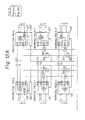
- Figure 14 is a diagram showing a construction for the ninth embodiments of the present invention.
- reference numeral 140 and 140' each denote a protection piece of optical terminal equipment, 141, ⁇ 144, and 141', ⁇ 144' each denote a working piece of optical terminal equipment
- L 0 denotes a protection transmission line
- L 1 , L 2 , ⁇ L 4 each denote a working transmission line
- C1', C2', ⁇ C8' each denote an unidirectional optical coupler or optical switch
- 700, 630, 640, 650, and 660 each denote an optical signal transmitting unit, 701, 631, 641, 651, and 661 each denote an optical signal receiving unit, 702 to 705, 632 to 635, 642, 643, 652, and 662 each denote a pair of an optical signal transmitting unit and an optical signal receiving unit
- 706, 636, 646, 656, and 666 each denote a switch unit, 707, 637, 647, 657, and
- the transmission rate of the protection transmission line L 0 and the working transmission line L 1 is, for example, 2.4 GHz
- the transmission rate of each path of optical signals between the protection piece of optical terminal equipment 140 and the working pieces of optical terminal equipment 141, ⁇ 144 (and each of the optical signal transmitting units and the optical signal receiving units in each pair of units 702 to 705, 632 to 635, 642 643, 652, and 662) is, for example, 600 MHz.
- transmission rates of the working transmission lines L 1 , L 2 , ⁇ L 4 are not the same, and the minimum transmission rate is 600 MHz.
- transmission of optical signals between the protection piece of optical terminal equipment 140 and the working pieces of optical terminal equipment 141, ⁇ 144 is carried out at the transmission rate which is equal to the minimum transmission rate of the working transmission lines L 1 , L 2 , ⁇ L 4 , and each of the protection piece of optical terminal equipment 140 and the working pieces of optical terminal equipment 141, ⁇ 144 comprises one or more pairs of an optical signal transmitting unit and an optical signal receiving unit for realizing the transmission.
- an optical signal received through the protection transmission line L 0 is converted to an electric signal in the optical signal receiving unit 701, and the electric signal is demultiplexed to a plurality of electric signals of the above minimum transmission rate of the working transmission lines L 1 , L 2 , ⁇ L N , in the demultiplexer 707.
- the protection transmission line L 0 is used by the working pieces of optical terminal equipment 141, ⁇ 144
- the demultiplexed electric signals are supplied through the switch unit 706 to the optical signal transmitting units in the pairs of units 702 to 705 to be respectively transmitted to the corresponding working pieces of optical terminal equipment 141, ⁇ 144.
- optical signals transmitted from the working pieces of optical terminal equipment 141, ⁇ 144 to the protection piece of optical terminal equipment 140 are received in the pairs of units 702 to 705, and are respectively converted to electric signals.
- the electric signals are supplied through the switch unit 706 to the multiplexer 707 to be multiplexed to an electric signal of high transmission rate (2.4 GHz).
- the multiplexed electric signal is converted to an optical signal in the optical signal transmitting unit 700 to be transmitted through the protection transmission line L 0 .
- tributary signals are first multiplexed to electric signals of the minimum transmission rate (600 MHz) in the multiplexer in the portion 638, 648, 658, or 668.
- the electric signals are supplied through the switch unit 636, 646, 656,or 666 to the multiplexer 637, 647, 657, or 667 to be multiplexed to an electric signal of the transmission rate of the working transmission line L 1 , L 2 , or L 4 .
- the multiplexed electric signal is converted to an optical signal in the optical signal transmitting unit 630, 640, 650, or 660 to be transmitted through the corresponding working transmission line L 1 , L 2 , or L 4 .
- an optical signal received through the corresponding working transmission line L 1 , L 2 , or L 4 is converted to an electric signal in the optical signal receiving unit 631, 641, 651, or 661.
- the electric signal is demultiplexed to a plurality of electric signals of the minimum transmission rate in the demultiplexer 637, 547, 657, or 667.
- the demultiplexed electric signals are supplied through the switch unit 636, 646, 656, or 666 to the multiplexer in the portion 638, 648, 658, or 668 to be demultiplexed to tributary signals.
- the above electric signals output from the portion 638, 648, 658, or 668 are supplied through the switch unit 636, 646, 656, or 666 to the pairs of units 632 to 635, 642 643, 652, and 662 to be transmitted to the protection piece of optical terminal equipment 140.
- the optical signals transmitted from the protection piece of optical terminal equipment 140 to the working piece of optical terminal equipment which uses the protection piece of optical terminal equipment 140 are received by the optical signal receiving unit in the pair of units 632 to 635, 642 643, 652, and are converted therein to an electric signal of the minimum transmission rate.
- the electric signals are supplied through the switch unit 636, 646, 656, or 666 to the portion 638, 648, 658, or 668, and are demultiplexed therein to tributary signals.
- the paths of the optical signals between the respective optical signal transmitting units and the optical signal receiving units in the working pieces of optical terminal equipment and the corresponding units in the protection piece of optical terminal equipment 140 are provided by using the optical couplers or optical switches C1', C2', ⁇ C8' in a similar manner to the fifth, sixth, and seventh embodiments.
- working pieces of optical terminal equipment respectively containing working transmission lines of various transmission rates can efficiently use a protection transmission line having a high transmission rate.
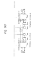
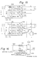
- Figure 15 is a diagram showing a construction for the tenth embodiments of the present invention.
- reference numeral 720 denotes an interface circuit for tributary signals
- 721 denotes a switch unit
- 722, 724, 732, and 734 each denote a multiplexer
- 723, 725, 733, and 735 each denote a demultiplexer
- 726, 728, 736, and 738 each denote an optical signal transmitting unit
- 727, 729, 737, and 729 each denote an optical signal receiving unit
- 351 and 352 each denote an optical coupler or optical switch.
- the interface circuits 720 and 730 are each the same as the interface circuit 161 in Fig. 4, and the interface circuits 720 and 730 in Fig. 15 may contain a construction equivalent to the multiplexer/demultiplexer 162.
- the switch unit 721 is the same as the construction of Fig. 8, and the switch unit 731 is the same as the construction of Fig. 7.
- multiplexers and demultiplexers are provided on the side of the optical signal transmitting units and the optical signal receiving units.
- the multiplexer 722 in the protection piece of optical terminal equipment comprises a construction for synchronizing the signals received from the working pieces of optical terminal equipment, with a clock signal in the protection piece of optical terminal equipment 150.
- reference numeral 800 denotes a clock generator
- 81l to 81n each denotes a buffer memory (FIFO memory)
- 820 denotes a justification circuit
- 830 denotes a multiplexing circuit.
- Each bit of the electric signals to be multiplexed are respectively input into the corresponding memories 81l to 81n synchronizing with writing clocks which respectively synchronize with the electric signals input into the memory, and each bit written in each memory is read and supplied to the multiplexing circuit 830 synchronizing with a reading clock which synchronizes with the clock generated in the clock generator 800 in the protection piece of optical terminal equipment 150.
- the frequency of the reading clock is set to be a little higher than the frequencies of the writing clocks.
- the justification control circuit 820 supplies the writing clocks and the reading clock to the memories 81l to 81n and the multiplexing circuit 830, compares phases of the writing clocks and the reading clock, and stops supplying of one cycle of the reading clock to each of the memories 81l to 81n and the multiplexing circuit 830 when the same bit is to be read twice from the memory if the cycle of the reading clock is supplied thereto.
- the above construction for synchronization may be provided in the other multiplexers 724, 732, and 734 in the construction of Fig. 15.
- an optical signal transmitted through the protection transmission line L 0 is converted to an electric signal in the optical signal receiving unit 723, and then the electric signal is demultiplexed in the demultiplexer 723.
- the demultiplexed electric signals are supplied through the switch unit 721 to the multiplexer 724.
- the electric signals are multiplexed in the multiplexer 724, and the multiplexed electric signal is converted to an optical signal in the optical signal transmitting unit 728 to be transmitted to the corresponding working piece of optical terminal equipment.
- an optical signal transmitted from a working piece of optical terminal equipment is converted to an electric signal in the optical signal receiving unit 729, and the converted electric signal is demultiplexed in the demultiplexer 725.
- Electric signals generated by the demultiplexer 725 are supplied through the switch unit 721 to the multiplexer 722.
- the multiplexer 722 multiplexes the supplied electric signals to an electric signal synchronizing the signals with the clock signal generated therein as explained above, and the multiplexed electric signal is converted to an optical signal in the optical signal transmitting unit 726 to be transmitted through the protection transmission line L 0 .
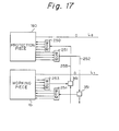
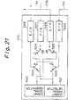
- Figure 17 is a diagram showing a construction for the eleventh embodiments of the present invention.
- reference numeral 160 denotes an protection piece of optical terminal equipment
- 16i denotes a working piece of optical terminal equipment
- 34i and 35i each denote an optical coupler or optical switch
- 250 and 254 each denote a wavelength division demultiplexer
- 251 and 253 each denote a wavelength division multiplexer
- 252 and 255 each denote an optical fiber.
- the wavelength division multiplexer 251 converts a plurality of signals into a plurality of optical signals of respectively different wavelengths, and multiplexes the plurality of optical signals to be transmitted through an optical fiber 252.
- the wavelength division demultiplexer 254 receives the wavelength division multiplexed optical signal through the optical fiber 252 and the optical coupler or optical switch 35i, and demultiplexes the multiplexed optical signal into a plurality of signals as those output from the protection piece of optical terminal equipment 160.
- a plurality of signals to be transmitted from the working piece of optical terminal equipment 16i to the protection piece of optical terminal equipment 160 are wavelength division multiplexed in the wavelength division multiplexer 253.
- the multiplexed optical signal is transmitted through the optical coupler or optical switch 34i and the optical fiber 255 to the wavelength division demultiplexer 250, and is then demultiplexed to the above signals output from the working piece of optical terminal equipment 16i.
- the transmission between the protection piece of optical terminal equipment and the working pieces of optical terminal equipment are carried out through a small number of optical fibers.
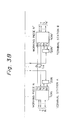
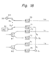
- FIG. 18 is a diagram showing a construction for confirming the above normality as the eleventh embodiment of the present invention.
- reference numeral 60 denotes a dummy signal generator
- 61 denotes a signal detector
- 70, and 72 to 75 each denote an optical signal transmitting unit
- 81 and 82 each denote a hybrid circuit
- S 3 and S 4 each denote an optical switch
- S 1 and S 2 each denote an electric switch.
- the dummy signal generator 60 and the signal detector 61 are provided in the protection piece of optical terminal equipment.
- the dummy signal generator 60 generates a dummy signal, and the dummy signal is transmitted through the protection transmission line L 0 between the protection pieces of optical terminal equipment in the optical terminal stations A and B.
- the dummy signal transmitted through the protection transmission line L 0 is detected by another signal detector (not shown) in the other optical terminal station to confirm the normality of the protection transmission line L 0 .
- the hybrid circuits 81 and 82 are respectively provided in two working pieces of optical terminal equipment. In the normal condition, an electric signal to be transmitted from each working piece of optical terminal equipment to the protection piece of optical terminal equipment, is supplied through the hybrid circuit 81 or 82 to the optical signal transmitting units 72 and 73, or 74 and 75. Thus, the electric signals from the hybrid circuits 81 and 82 are respectively applied to the optical signal transmitting units 73 and 75 to be converted to optical signals.
- the optical switches S 1 and S 2 are controlled so that the optical signals generated in the optical signal transmitting units 73 and 75, are alternatively (cyclically) transmitted through the optical signal receiving unit 71 to the signal detector 61 in the protection piece of optical terminal equipment. Thus, the normality of the paths of optical signals from the working pieces of optical terminal equipment to the protection piece of optical terminal equipment can be confirmed by the signal detector 61.
- the paths of optical signals from the protection piece of optical terminal equipment to the working pieces of optical terminal equipment can be confirmed by providing a signal detector in each working piece of optical terminal equipment, and cyclically transmitting a dummy signal to each working piece of optical terminal equipment.
- Figure 19 is a diagram showing a construction and flows of optical and electric signals of the thirteenth embodiment of the present invention.
- reference numeral 170 and 170 each denote a protection piece of optical terminal equipment
- 171, 172, 173, 171', 172', and 173' each denote a working piece of optical terminal equipment
- 770 and 770' each denote a bidirectional optical path connecting the protection piece of optical terminal equipment and the working piece of optical terminal equipment which is located at
- an optical input port of the optical signal transmitting unit 863 of the protection piece of optical terminal equipment 170 and an optical input port of the optical signal receiving unit 892 may be connected by an unidirectional optical path
- an optical input port of the optical signal transmitting unit 873 of the working piece of optical terminal equipment 171 which is located at a location nearest to the protection piece of optical terminal equipment 170, and an optical output port of the optical signal receiving unit 862 of the protection piece of optical terminal equipment 170 may be connected with an unidirectional optical path 771.
- Parallel to the relay operation normal operations of multiplexing tributary signals TSi, converting and transmitting the multiplexed signal through the working transmission line Li, receiving and converting an optical signal, and demultiplexing the converted signal to tributary signals TSi, are carried out in the respective working pieces of optical terminal equipment 171 and 173, as indicated by arrows b and f in Fig. 19.
- the protection transmission line L 0 is connected to the optical signal transmitting unit 862 and the optical signal receiving unit 863.
- the tributary signals TS2 are multiplexed in the working piece of optical terminal equipment 172, and the multiplexed signal is converted to an optical signal in the optical signal transmitting unit 882. Then, the optical signal is transmitted through the path 772, the optical signal receiving unit 873, the path d, the optical signal transmitting unit 872, and the path 771 to the protection piece of optical terminal equipment 170.
- the optical signal output from the optical signal transmitting unit 862 is transmitted through the path 770 , the optical signal receiving unit 893, the path a, the optical signal transmitting unit 892, the path 773 to the optical signal receiving unit 883 of the working piece of optical terminal equipment 172 to be converted and demultiplexed to the tributary signals TS2.
- reference numeral 510 denotes a multiplexer/demultiplexer
- 511, 512, and 513 each denote a switch
- 514 and 516 each denote an optical signal transmitting unit
- 515 and 517 each denote an optical signal receiving unit.
- Each of the switches 511, 512, and 513 has two contacts A and B.
- the switches 511, 512, and 513 are respectively switched to their contact B.
- the switches 511, 512, and 513 are respectively switched to their contact A.
- Figure 21 is a diagram showing a construction of the protection piece of optical terminal equipment 170 in the construction of Fig. 19.
- reference numeral 520 denotes a dummy signal generator
- 521 denotes a dummy signal detector
- 522, 523, 524, and 525 each denote a switch
- 526 and 528 each denote an optical signal transmitting unit
- 527 and 529 each denote an optical signal receiving unit.
- Each of the switches 522, 523, 524, and 525 has two contacts A and B. In the normal condition, the switches 522 and 524 are respectively switched to the contact A. When one of the working pieces of optical terminal equipment is to be connected to the protection transmission line L 0 , all the switches 522, 523, 524, and 525 are respectively switched to the contact B.
- reference numeral 545 denotes a switch, and the switch 545 has two contacts A and B.
- the optical signal transmitting unit 516 and the optical signal receiving unit 517 can be bypassed when a trouble occurs in the optical signal transmitting unit 516, the optical signal receiving unit 517, and the switch 513.
- Reference signs in the claims are intended for better understanding and shall not limit the scope.
Description
Claims (46)
- A system for optical communication between first and second optical terminal stations (A, B), comprising:characterised in that the system further comprises :a plurality of working optical transmission lines (L1, L2, ..., LN) each for connecting between said first and second optical terminal stations (A, B), and transmitting optical signals in two directions between said first and second optical terminal stations (A, B);a protection optical transmission line (L0), provided as a stand-by bidirectional optical transmission line for at least a part of said working optical transmission lines (L1, L2 ..., LN), each for connecting between said first and second optical terminal stations (A, B), and transmitting an optical signal between said first and second optical terminal stations (A, B); andsaid first and second optical terminal stations (A, B) ;whereby each of the first and second optical terminal stations (A, B) comprisesa plurality of working pieces of optical terminal equipment (101, 102, ... 10N, 101', 102 ..., 10N'), provided corresponding to the respective working optical transmission lines (L1, L2, ..., LN),a protection piece of optical terminal equipment (100, 100'), provided corresponding to said protection optical transmission line (L0),a plurality of bidirectional optical signal paths, provided corresponding to the respective working pieces of optical terminal equipment (101, ..., 10N, 101', ..., 10N'), and each operative to connect the corresponding working piece of optical terminal equipment (101, ..., 10N, 101', ..., 10N'), with said protection piece of optical terminal equipment (100, 100');whereby each of said plurality of working pieces of optical terminal equipment (101, ..., 10N, 101', ..., 10N') comprisesat least one bidirectional tributary port for transmitting and receiving tributary signals (TS1, ..., TSN, TS1', ..., TSN') therethrough,first and second bidirectional optical ports each for transmitting and receiving optical signals therethrough, said first bidirectional optical port being connected to one of the working optical transmission lines (L1 ..., LN) corresponding to said working piece of optical terminal equipment (101, ..., 10N, 101', ..., 10N'), and said second bidirectional optical port being connected to one of the bidirectional optical signal paths corresponding to said working piece of optical terminal equipment (101, ..., 10N, 101', ..., 10N'),first receiving means for receiving tributary signals (TS1, ..., TSN, TS1', ..., TSN') from said at least one tributary port,first converting means for converting the received tributary signals (TS1, .., TSN, TS1', ..., TSN') to optical signals,first transmitting means (TX164) for transmitting said optical signals converted from said received tributary signals (TSi), through said first bidirectional optical port to the other of said optical terminal stations (B),second transmitting means (TX166) for transmitting said optical signals converted from said received tributary signals (TSi), through said second bidirectional optical port to said protection piece (100, 100')of optical terminal equipment,second receiving means (RX165) for receiving optical signals transmitted from said other optical terminal station (B), through said first bidirectional optical port,third receiving means (RX167)for receiving optical signals transmitted from said protection piece of optical terminal equipment (100, 100'), through said second bidirectional optical port,second converting means for converting said optical signals received by either of said second and third receiving means, to tributary signals (TSi) to be transmitted from said at least one bidirectional tributary port, andthird transmitting means for transmitting said tributary signals (TSi) converted by said second converting means, from said at least one bidirectional tributary port;switch means (163) for activating the connections enabling the optical signals to pass through one of said first and second bidirectional optical ports in accordance with the operable or inoperable state of the corresponding working optical transmission line;whereby said protection piece of optical terminal equipment (100, 100') comprises,third and fourth bidirectional optical ports each for transmitting and receiving optical signals therethrough, said third bidirectional optical port being connected to said protection optical transmission line (L0), and said fourth bidirectional optical port operative to be connected to at least one of said plurality of bidirectional optical signal paths,fourth receiving means for receiving optical signals through said fourth bidirectional optical port from at least one of said plurality of working pieces (101, ..., 10N, 101', ..., 10N') of optical terminal equipment corresponding to said bidirectional optical signal path,fourth transmitting means for transmitting the received optical signals through said protection optical transmission line (L0) to the other optical terminal station (B),fifth receiving means for receiving optical signals from said other optical terminal station (B) through said third bidirectional optical port, andfifth transmitting means for transmitting the received optical signals through said fourth bidirectional optical port to said at least one of said plurality of working pieces of optical terminal equipment (101, ..., 10N, 101', ..., 10N') corresponding to said at least one bidirectional optical signal path.
- A system according to claim 1, wherein said protection piece of optical terminal equipment (100, 100') comprises:a dummy signal generating means (60) for generating a dummy signal which is to be transmitted through the protection optical transmission line (L0) when no working piece of optical terminal equipment (101, ..., 10N, 101', ..., 10N') is connected to the protection optical transmission line (L0), anda dummy signal connection switch means (S4) for connecting said dummy signal generating means (60) to said protection optical transmission line (L0) when no working piece of optical terminal equipment (101, ..., 10N, 101', .., 10N') is connected to the protection optical transmission line (L0).
- A system according to claim 1, wherein said protection piece of optical terminal equipment (100, 100') comprises:at least one bidirectional tributary port for transmitting and receiving low-priority tributary signals (LPS, LPS') therethrough,sixth receiving means for receiving low-priority tributary signals (LPS, LPS') from said at least one tributary port,third converting means for converting the received low-priority tributary signals (LPS, LPS') to optical signals,sixth transmitting means for transmitting said optical signals converted from said received low-priority tributary signals (LPS, LPS'), through said first bidirectional optical port to the other of said optical terminal stations (A, B),seventh receiving means for receiving optical signals transmitted from said other optical terminal station (A, B), through said first bidirectional optical port,fourth converting means for converting said optical signals received by said sixth receiving means, to low priority tributary signals (LPS, LPS') to be transmitted from said at least one bidirectional tributary port, andseventh transmitting means for transmitting said low-priority tributary signals (LPS, LPS') converted by said fourth converting means, from said at least one bidirectional tributary port,a substitute signal connection switch means for connecting said third transmitting means to said protection optical transmission line (L0) when no working piece of optical terminal equipment (101, ..., 10N, 101', ..., 10N') is connected to the protection optical transmission line (L0).
- A system according to claim 1, wherein said protection piece of optical terminal equipment (100, 100') operates in synchronization with a clock signal, and the fourth and fifth transmitting means respectively comprise synchronizing means (811, ... 81n, 820) for regenerating said optical signals received through said fourth and fifth bidirectional optical ports, at timing of said clock signal before the transmitting operations by the fourth and fifth transmitting means.
- A system according to claim 4, wherein said fourth and fifth receiving means respectively comprise optical-to-electric conversion means (E/0) for converting the respectively received optical signals into electric signals, and demultiplexer means for demultiplexing the converted electric signals into demultiplexed electric signals,said fourth and fifth transmitting means respectively comprise multiplexer means for multiplexing the respectively received electric signals into multiplexed electric signals, and electric-to-optical conversion means (E/0) for converting the multiplexed electric signals into optical signals, andsaid protection piece of optical terminal equipment (100, 100') comprises connection means for supplying said demultiplexed electric signals generated in said fourth and fifth receiving means to said fourth and fifth transmitting means, respectively.
- A system according to claim 4, wherein a wavelength of said optical signal transmitted from said protection piece of optical terminal (100, 100') equipment to said working pieces of optical terminal equipment (101, ..., 10N, 101', ..., 10N') and a wavelength of said optical signal transmitted from said respective working pieces of optical terminal equipment (101, ..., 10N, 101', ..., 10N') to said protection piece of optical terminal equipment (100, 100'), are the same.
- A system according to claim 1, wherein each of said plurality of bidirectional optical signal paths comprise wavelength division multiplex means (251) for transforming a plurality of optical signals to optical signals respectively having different wavelengths, and multiplexing the plurality of optical signals to transmit the plurality of optical signals between the protection piece of optical terminal equipment (100, 100') and one of the plurality of working pieces of optical terminal equipment (101, ..., 10N, 101', ..., 10N') through an optical transmission line.
- A system according to claim 1, wherein each of said plurality of working pieces of optical terminal equipment (101, ..., 10N, ..., 101', ..., 10N') comprises,receiving signal switch means (169) for selecting the optical signals received through one of said first and second bidirectional optical ports, to be converted to said tributary signals (TSi) by said second converting means, andtransmitting signal switch means (168) for selecting one of said first and second transmitting means to operate.
- A system according to claim 8, wherein each of said first and second optical terminal stations (A, B) further comprises switch control means for controlling the operations of said receiving signal switch means (169) and said transmitting signal switch means (168).
- A system according to claim 8, wherein said plurality of bidirectional optical signal paths in each of first and second optical terminal stations (A, B) comprise:
a first signal coupling/branching means (300, 300'), provided corresponding to the protection piece of optical terminal equipment (100, 100'), said first signal coupling/branching means (300, 300') having one coupled bidirectional optical port and a plurality of uncoupled bidirectional optical ports provided corresponding to the respective working pieces of optical terminal equipment (101, ..., 10N, 101', ..., 10N'), the plurality of uncoupled bidirectional optical ports are respectively connected to said second bidirectional optical port of the corresponding working pieces of optical terminal equipment (101, ..., 10N') the coupled bidirectional optical port being connected to said fourth bidirectional optical port of said protection piece of optical terminal equipment (100, 100'), an optical signal input into said coupled bidirectional optical port in each first signal coupling/branching means (300, 300') branching therein to be output from said plurality of uncoupled bidirectional optical ports, and an optical signal input into either of said plurality of uncoupled bidirectional optical ports in the first signal coupling/branching means (300, 300') passing therethrough to be output from said coupled bidirectional optical port. - A system according to claim 10, wherein said first and second bidirectional optical ports of each of said plurality of working pieces of optical terminal equipment (101, ..., 10N') each have an optical input port for the reception by said third receiving means (RX167), and an optical output port for the transmission by said second transmitting means (TX166), and said protection piece of optical terminal equipment (100, 100') having an optical input port for the reception by said fourth receiving means, and an optical output port for the transmission by said fifth transmitting means;
said plurality of bidirectional optical signal paths further comprises:a second signal coupling/branching means (200, 200'), provided corresponding to the protection piece of optical terminal equipment (100, 100'), said second signal coupling/branching means (200, 200') having one coupled bidirectional optical port and two uncoupled unidirectional ports, said coupled bidirectional optical port of the second signal coupling/branching means being connected to said coupled bidirectional optical port of said first signal coupling/branching means (300, 300'), said two uncoupled unidirectional ports of the second signal coupling/branching means (200, 200') are respectively connected to said optical input port and said optical output port of said protection piece of optical terminal equipment (100, 100'), an optical signal input into said coupled bidirectional optical port in the second signal coupling/branching means (200, 200') passing therethrough to be input into the protection piece of optical terminal equipment (100, 100') through the optical input port thereof, and an optical signal output from the optical output port of the protection piece of optical terminal equipment (100, 100') passing through the second signal coupling/branching means (200, 200') to be output from said coupled bidirectional optical port thereof to the first signal coupling/branching means (300, 300'); anda plurality of third signal coupling/branching means (201, 202, ... 20N), respectively provided corresponding to said plurality of working pieces of optical terminal equipment (101, ..., 10N), each of said third signal coupling/branching means (201, ..., 20N) having one coupled bidirectional optical port and two uncoupled unidirectional ports, said coupled bidirectional optical port of each third signal coupling/branching means (201, 202, ..., 20N) being connected to one of said plurality of uncoupled bidirectional optical ports of said first signal coupling/branching means (300, 300'), said two uncoupled unidirectional ports of each third signal coupling/branching means (201, ..., 20N) are respectively connected to said optical input port and said optical output port of one of said plurality of working pieces of optical terminal equipment (101, ..., 10N) corresponding to said each third signal coupling/branching means (201, ..., 20N), an optical signal input into said coupled bidirectional optical port in each third signal coupling/branching means (201, ..., 20N) passing therethrough to be applied to the working piece of optical terminal equipment (101, ..., 10N) corresponding to the third signal coupling/branching means (201, ..., 20N) through the one of the uncoupled unidirectional ports of the third signal coupling/branching means (201, ..., 20N) and the optical input port of the working piece of optical terminal equipment (101, ..., 10N), and an optical signal output from the optical output port of the working piece of optical terminal equipment (101, ..., 10N) corresponding to the third signal coupling/branching means (201, ..., 20N), being input through the other of said two uncoupled unidirectional ports of the third signal coupling/branching means (201, ..., 20N), and passing therethrough to be output from the coupled bidirectional optical port thereof to the first signal coupling/branching means (300, 300'). - A system according to claim 8, wherein said plurality of bidirectional optical signal paths in each of first and second optical terminal stations (A, B) comprise:a first unidirectional signal coupling/branching means (321, ..., 32N), provided corresponding to the protection piece (120, 120') of optical terminal equipment, said first unidirectional signal coupling/branching means (321, ..., 32N) having one coupled signal unidirectional port and a plurality of uncoupled unidirectional ports provided corresponding to the respective working pieces of optical terminal equipment (121, ..., 12N), the plurality of uncoupled unidirectional ports are respectively connected to said optical output ports in the second bidirectional optical ports of the corresponding working pieces of optical terminal equipment (121, ..., 12N), the coupled signal unidirectional port being connected to the optical input port of said fourth bidirectional optical port of said protection piece of optical terminal equipment (120), an optical signal input into one of said uncoupled unidirectional ports in the first unidirectional signal coupling/branching means (321, ..., 32N) being output from said coupled signal unidirectional port to be input through the optical input port of the protection piece of optical terminal equipment (120) into the protection piece of optical terminal equipment (120); anda second unidirectional signal coupling/branching means (331, ..., 33N), provided corresponding to the protection piece of optical terminal equipment (121, ..., 12N), said second unidirectional signal coupling/branching means (331, ..., 33N) having one coupled signal unidirectional port and a plurality of uncoupled unidirectional ports provided corresponding to the respective working pieces of optical terminal equipment (121, ..., 12N), the plurality of uncoupled unidirectional ports are respectively connected to said optical input ports in the second bidirectional optical ports of the corresponding working pieces of optical terminal equipment (121, ..., 12N), the coupled signal unidirectional port being connected to the optical output port of said fourth bidirectional optical port of said protection piece of optical terminal equipment (120), an optical signal input into said coupled signal unidirectional port in the second unidirectional signal coupling/branching means (331, ..., 33N) being output from all of said uncoupled unidirectional ports to be applied through the optical input ports of the corresponding working pieces of optical terminal equipment (121, ..., 12N) to the respective working pieces of optical terminal equipment (121, ..., 12N).
- A system according to claim 8, wherein said plurality of bidirectional optical signal paths in each of first and second optical terminal stations comprise:one or more signal coupling/branching means (311, 312, ... 31N), provided corresponding to the respective working pieces of optical terminal equipment (111, ..., 11N) except one of the working pieces of optical terminal equipment located at location furthest from said protection piece of optical terminal equipment (110), each of said one or more signal coupling/branching means (311, ..., 31N) having one coupled bidirectional optical port and two uncoupled bidirectional optical ports, one of said two uncoupled bidirectional optical ports being connected to said second bidirectional optical port of the corresponding working piece of optical terminal equipment (111, ..., 11N), an optical signal input into said coupled bidirectional optical port in each signal coupling/branching means (311, ..., 31N) branching therein to be output from said two uncoupled bidirectional optical ports, and an optical signal input into either of said uncoupled bidirectional optical ports in each signal coupling/branching means (311, ..., 31N) passing therethrough to be output from said coupled bidirectional optical port;a furthest bidirectional optical connection path for connecting said second bidirectional optical port of said working piece of optical terminal equipment located at the furthest location from said protection piece of optical terminal equipment (110), with the other of said two uncoupled bidirectional optical ports of one of said one or more signal coupling/branching means (311, ..., 31N) located at a location nearest to said working piece of optical terminal equipment located at the furthest location;one or more bidirectional optical connection paths for connecting the other of said two uncoupled bidirectional optical ports of each of the one or more signal coupling/branching means (311, ..., 31N) with said coupled bidirectional optical port of one of said one or more signal coupling/branching means (311, .., 31N) located at a position further by one piece than said each signal coupling/branching means (311, ..., 31N) from said protection piece of optical terminal equipment (110), except when said each of said one or more signal coupling/branching means (311, ..., 31N) being said signal coupling/branching means (311, ..., 31N) located at the nearest location to said working piece of optical terminal equipment located at the furthest location; anda nearest bidirectional optical connection path for connecting said coupled bidirectional optical port of said signal coupling/branching means (311, ..., 31N) located at the nearest location to said protection piece of optical terminal equipment (110), to said fourth bidirectional optical port of the protection piece of optical terminal equipment (110).
- A system according to claim 13, wherein said first and second bidirectional optical ports of each of said plurality of working pieces of optical terminal equipment (111, ..., 11N) each having an optical input port for the reception by said third receiving means (RX167), and an optical output port for the transmission by said second transmitting means (TX166), and said protection piece of optical terminal equipment (110) each having an optical input port for the reception by said fourth receiving means, and an optical output port for the transmission by said fifth transmitting means;
whereby said plurality of bidirectional optical signal paths further comprises:a second signal coupling/branching means (210) for connecting said fourth bidirectional optical port of the protection piece of optical terminal equipment (110) with said coupled bidirectional optical port of said signal coupling/branching means located at the nearest location to the protection piece of optical terminal equipment (110), said second signal coupling/branching means (210) having one coupled bidirectional optical port and two uncoupled unidirectional ports, said coupled bidirectional optical port of the second signal coupling/branching means (210) being connected to said coupled bidirectional optical port of said signal coupling/branching means located at the nearest location to the protection piece of optical terminal equipment (110), said two uncoupled unidirectional ports of the second signal coupling/branching means are respectively connected to said optical input port and said optical output port of said protection piece of optical terminal equipment (110), an optical signal input into said coupled bidirectional optical port in the second signal coupling/branching means (210) passing therethrough to be input into the protection piece of optical terminal equipment (110) through said one of the two uncoupled unidirectional ports of the second signal coupling/branching means (210) and the optical input port thereof, and an optical signal output from the optical output port of the protection piece of optical terminal equipment (110), being input into the second signal coupling/branching means (210) through the other of the two uncoupled unidirectional ports thereof, passing through the second signal coupling/branching means (210) to be output from said coupled bidirectional optical port thereof to the first signal coupling/branching means (311); anda plurality of third signal coupling/branching means (211, 212, ... 21N) for connecting the second bidirectional optical ports of the respective working pieces of optical terminal equipment (111, ..., 11N) with said one of the two uncoupled unidirectional ports of the corresponding ones of said one or more signal coupling/branching means, each of said third signal coupling/branching means (211, ..., 21N) having one coupled bidirectional optical port and two uncoupled unidirectional ports, said coupled bidirectional optical port of each third signal coupling/branching means (211, ..., 21N) being connected to said other of the two uncoupled unidirectional ports of one of the one or more signal coupling/branching means located at a position further by one piece than said one of the one or more signal coupling/branching means corresponding to said each third signal coupling/branching means (211, ..., 21N) from said protection piece of optical terminal equipment, said two uncoupled unidirectional ports of each third signal coupling/branching means (211, ..., 21N) are respectively connected to said optical input port and said optical output port of said one of said plurality of working pieces of optical terminal equipment (111, ..., 11N) corresponding to said each third signal coupling/branching means (211, ..., 21N), an optical signal input into said coupled bidirectional optical port in each third signal coupling/branching means (211, ..., 21N) passing therethrough to be applied to the working piece of optical terminal equipment (111, ..., 11N) corresponding to the third signal coupling/branching means (211, ..., 21N) through one of the uncoupled unidirectional ports thereof and the optical input port of the working piece of optical terminal equipment (111, ..., 11N), and an optical signal output from the optical output port of the working piece of optical terminal equipment (111, ..., 11N) corresponding to the third signal coupling/branching means (211, ..., 21N), being input through the other of said two uncoupled unidirectional ports of the third signal coupling/branching means (211, ..., 21N), and passing therethrough to be output from the coupled bidirectional optical port thereof to said one of the one or more signal coupling/branching means located at a position further by one piece than said one of the one or more signal coupling/branching means corresponding to said each third signal coupling/branching means (211, ..., 21N) from said protection piece of optical terminal equipment (110). - A system according to claim 14, wherein each of said one or more signal coupling/branching means and a corresponding one of the third coupling/branching means (211, ..., 21N) are realized by an optical coupler which comprises one coupled bidirectional optical port, one uncoupled bidirectional optical port, and two uncoupled unidirectional optical ports, said coupled bidirectional optical port and said uncoupled bidirectional optical port in the optical coupler respectively correspond to said coupled bidirectional optical port and said other of said each of said one or more signal coupling/branching means, said two uncoupled unidirectional optical ports in said optical coupler respectively correspond to said two uncoupled unidirectional ports of the corresponding third signal coupling/branching means (211, ..., 21N).
- A switching system according to claim 14, wherein a wavelength of said optical signal transmitted from said protection piece of optical terminal equipment (110) to said working pieces of optical terminal equipment (111, ..., and a wavelength of said optical signal transmitted from said respective working pieces of optical terminal equipment (111, ..., 11N) to said protection piece of optical terminal equipment (110), are different, and said third signal coupling/branching means (211, ..., 21N) comprises filter means for passing therethrough optical signals of the wavelength of said optical signal transmitted from said protection piece of optical terminal equipment (110) to said working pieces of optical terminal equipment (111, ..., 11N).
- A system according to claim 8, wherein said first and second bidirectional optical ports of each of said plurality of working pieces of optical terminal equipment (121, ..., 12N) each having an optical input port for the reception by said third receiving means (RX167), and an optical output port for the transmission by said second transmitting means (TX166), and said protection piece of optical terminal equipment (100) each having an optical input port for the reception by said fourth receiving means, and an optical output port for the transmission by said fifth transmitting means;
whereby said plurality of bidirectional optical signal paths in each of first and second optical terminal stations comprise:one or more first unidirectional signal coupling/branching means (321, 322, ..., 32N), provided corresponding to the respective working pieces of optical terminal equipment (121, ..., 12N) except one of the working pieces of optical terminal equipment located at location furthest from said protection piece of optical terminal equipment (120), each of said one or more first unidirectional signal coupling/branching means (321, ..., 32N) having one coupled unidirectional optical port and two uncoupled unidirectional optical ports, one of said two uncoupled unidirectional optical ports being connected to said optical output port of said second bidirectional optical port of the corresponding working piece of optical terminal equipment, an optical signal input into either of said uncoupled unidirectional optical ports in each first unidirectional signal coupling/branching means (321, ..., 32N) passing therethrough to be output from said coupled unidirectional optical port;a first furthest unidirectional optical connection path for connecting said optical output port of said second bidirectional optical port of said working piece of optical terminal equipment located at the furthest location from said protection piece of optical terminal equipment (120), with the other of said two uncoupled unidirectional optical ports of one of said one or more first unidirectional signal coupling/branching means located at location nearest to said working piece of optical terminal equipment located at the furthest location;one or more first unidirectional optical connection paths for connecting the other of said two uncoupled unidirectional optical ports of each of the one or more first unidirectional signal coupling/branching means with said coupled unidirectional optical port of one of said one or more first unidirectional signal coupling/branching means (321, ..., 32N) located at a position further by one piece than said each first unidirectional signal coupling/branching means from said protection piece of optical terminal equipment (120), except when said each of said one or more first unidirectional signal coupling/branching means (321, ..., 32N) being said first unidirectional signal coupling/branching means located at the nearest location to said working piece of optical terminal equipment located at the furthest location;a first nearest unidirectional optical connection path for connecting said coupled unidirectional optical port of said first unidirectional signal coupling/branching means located at the nearest location to said protection piece of optical terminal equipment (120), to said optical input port of said fourth bidirectional optical port of the protection piece of optical terminal equipment (120);one or more second signal coupling/branching means (331, 332, ... 33N), provided corresponding to the respective working pieces of optical terminal equipment (121, ..., 12N) except said working piece of optical terminal equipment located at the furthest location from said protection piece of optical terminal equipment (120), each of said one or more second signal coupling/branching means (331, .., 33N) having one coupled unidirectional optical port and two uncoupled unidirectional optical ports, one of said two uncoupled unidirectional optical ports being connected to said optical input port of said second bidirectional optical port of the corresponding working piece of optical terminal equipment, an optical signal input into said coupled unidirectional optical port in each second signal coupling/branching means (331, ..., 33N) branching therein to be output from said two uncoupled unidirectional optical ports;a second furthest unidirectional optical connection path for connecting said optical input port of said second bidirectional optical port of said working piece of optical terminal equipment located at the furthest location from said protection piece of optical terminal equipment (120), with the other of said two uncoupled unidirectional optical ports of one of said one or more second signal coupling/branching means (331, ..., 33N) located at location nearest to said working piece of optical terminal equipment located at the furthest location;one or more second unidirectional optical connection paths for connecting the other of said two uncoupled unidirectional optical ports of each of the one or more second signal coupling/branching means (331, ..., 33N) with said coupled unidirectional optical port of one of said one or more second signal coupling/branching means (331, ..., 33N) located at a position further by one piece than said each second signal coupling/branching means (331, ..., 33N) from said protection piece of optical terminal equipment (120), except when said each of said one or more second signal coupling/branching means (331, ..., 33N) being said second signal coupling/branching means (331, ..., 33N) located at the nearest location to said working piece of optical terminal equipment located at the furthest location; anda second nearest unidirectional optical connection path for connecting said coupled unidirectional optical port of said second signal coupling/branching means located at the nearest location to said protection piece of optical terminal equipment (120), to said optical output port of said fourth bidirectional optical port of the protection piece of optical terminal equipment (120). - A system according to claim 1, wherein each of said plurality of working pieces of optical terminal equipment (101, ..., 10N) comprises a receiving signal switch means (173) for selecting the optical signals received through one of said first and second bidirectional optical ports, to be converted to said tributary signals (TSi) by said second converting means, and
both of said first and second transmitting means operating concurrently. - A system according to claim 18, wherein said plurality of bidirectional optical signal paths in each of first and second optical terminal stations comprise:
a first signal switching means (300), provided corresponding to the protection piece of optical terminal equipment (100), said first signal switching means (300) having one first-type bidirectional optical port and a plurality of second-type bidirectional optical ports, said first-type bidirectional optical port being connected to said fourth bidirectional optical port of said protection piece of optical terminal equipment (100), said plurality of second-type bidirectional optical ports are respectively connected to said second bidirectional optical ports of the corresponding working pieces of optical terminal equipment (101, ..., 10N), an optical signal input into said first-type bidirectional optical port in the first signal switching means being output from a selected one of said plurality of second-type bidirectional optical ports, and an optical signal input into either of said plurality of second-type bidirectional optical ports in the first signal switching means passing therethrough to be output from said first-type bidirectional optical port. - A system according to claim 19, wherein each of said first and second optical terminal stations (A, B) further comprises switch control means for controlling the operations of said receiving signal switch means and said one or more signal switching means.
- A system according to claim 20, wherein said first and second bidirectional optical ports of each of said plurality of working pieces of optical terminal equipment (101, ..., 10N) each having an optical input port for the reception by said third receiving means, and an optical output port for the transmission by said second transmitting means, and said protection piece of optical terminal equipment (100) each having an optical input port for the reception by said fourth receiving means, and an optical output port for the transmission by said fifth transmitting means;
said plurality of bidirectional optical signal paths further comprises:a first signal coupling/branching means (200), provided corresponding to the protection piece of optical terminal equipment (100), said first signal coupling/branching means (200) having one coupled bidirectional optical port and two uncoupled unidirectional ports, said coupled bidirectional optical port of the first signal coupling/branching means (200) being connected to said first-type bidirectional optical port of said first signal switching means, said two uncoupled unidirectional ports of the first signal coupling/branching means (200) are respectively connected to said optical input port and said optical output port of said protection piece of optical terminal equipment (100), an optical signal input into said coupled bidirectional optical port in the first signal coupling/branching means (200) passing therethrough to be input into the protection piece of optical terminal equipment (100) through the optical input port thereof, and an optical signal output from the optical output port of the protection piece of optical terminal equipment (100), passing through the first signal coupling/branching means (200) to be output from said coupled bidirectional optical port thereof to the first signal switching means; anda plurality of second signal coupling/branching means (201, 202, ... 20N), respectively provided corresponding to said plurality of working pieces of optical terminal equipment (101, ..., 10N), each of said second signal coupling/branching means (201, ..., 20N) having one coupled bidirectional optical port and two uncoupled unidirectional ports, said coupled bidirectional optical port of each second signal coupling/branching means (201, ..., 20N) being connected to one of said plurality of uncoupled bidirectional optical ports of said first signal switching means, said two uncoupled unidirectional ports of each second signal coupling/branching means are respectively connected to said optical input port and said optical output port of one of said plurality of working pieces of optical terminal equipment (101, ..., 10N) corresponding to said each second signal coupling/branching means (201, ..., 20N), an optical signal input into said coupled bidirectional optical port in each second signal coupling/branching means (201, ..., 20N) passing therethrough to be applied to the working piece of optical terminal equipment (101, ..., 10N) corresponding to the second signal coupling/branching means (201, ..., 20N) through the one of the uncoupled unidirectional ports thereof and the optical input port of the working piece of optical terminal equipment (101, ..., 10N), and an optical signal output from the optical output port of the working piece of optical terminal equipment (101, ..., 10N) corresponding to the second signal coupling/branching means (201, ..., 20N), being input through the other of said two uncoupled unidirectional ports of the second signal coupling/branching means (201, ..., 20N), and passing through the second signal coupling/branching means (201, ..., 20N) to be output from the coupled bidirectional optical port thereof to the first signal switching means. - A system according to claim 18, wherein said plurality of bidirectional optical signal paths in each of first and second optical terminal stations (A, B) comprise:a first unidirectional signal switching means, provided corresponding to the protection piece of optical terminal equipment (100), said first unidirectional signal switching means having one first-type unidirectional port and a plurality of second-type unidirectional ports, said plurality of second-type unidirectional ports being provided corresponding to the respective working pieces of optical terminal equipment (101, ..., 10N), the plurality of second-type unidirectional ports being respectively connected to said optical output ports in the second bidirectional optical ports of the corresponding working pieces of optical terminal equipment (101, ..., 10N), the first-type unidirectional port being connected to the optical input port of said fourth bidirectional optical port of said protection piece of optical terminal equipment (100), an optical signal input into one of said second-type unidirectional ports in the first unidirectional signal switching means being output from said first-type unidirectional port to be input into the protection piece of optical terminal equipment (100) through the optical input port of the protection piece thereof; anda second unidirectional signal switching means, provided corresponding to the protection piece of optical terminal equipment (100), said second unidirectional signal switching means having one first-type unidirectional port and a plurality of second-type unidirectional ports, said plurality of second-type unidirectional ports being provided corresponding to the respective working pieces of optical terminal equipment (101, ..., 10N), the plurality of second-type unidirectional ports being respectively connected to said optical input ports in the second bidirectional optical ports of the corresponding working pieces of optical terminal equipment (101, ..., 10N), the first-type unidirectional port being connected to the optical output port of said fourth bidirectional optical port of said protection piece of optical terminal equipment (100), an optical signal input into said first-type unidirectional port in the second unidirectional signal switching means being output from a selected one of said second-type unidirectional ports to be applied to the respective working pieces of optical terminal equipment (101, ..., 10N) through the optical input port thereof.
- A system according to claim 22, wherein each of said first and second optical terminal stations (A, B) further comprises switch control means for controlling the operations of said receiving signal switch means, and said first and second unidirectional signal switching means.
- A system according to claim 18, wherein said plurality of bidirectional optical signal paths in each of first and second optical terminal stations (A, B) comprise:one or more signal switching means (311, 312, ... 31N), provided corresponding to the respective working pieces of optical terminal equipment (111, ..., 11N) except one of the working pieces of optical terminal equipment located at location furthest from said protection piece of optical terminal equipment (110), each of said one or more having one second-type bidirectional optical port and two second-type bidirectional optical ports,one of said two second-type bidirectional optical ports of the signal switching means (311, ..., 31N) being connected to said second bidirectional optical port of the corresponding working piece of optical terminal equipment (111, ..., 11N), an optical signal input into said second-type bidirectional optical port in each signal switching means (311, ..., 31N) passing therethrough to be output from one of said two second-type bidirectional optical ports, and an optical signal input into one of said second-type bidirectional optical ports in each signal switching means (311, ..., 31N) passing therethrough to be output from said second-type bidirectional optical port;a furthest bidirectional optical connection path for connecting said second bidirectional optical port of said working piece of optical terminal equipment located at the furthest location from said protection piece of optical terminal equipment (110), with the other of said two second-type bidirectional optical ports of one of said one or more signal switching means located at location nearest to said one of the working pieces of optical terminal equipment located at the furthest location;one or more bidirectional optical connection paths for connecting the other of said two second-type bidirectional optical ports of each of said one or more signal switching means with said second-type bidirectional optical port of one of said one or more signal coupling/branching means located at a position further by one piece than said each signal coupling/branching means from said protection piece of optical terminal equipment (110), except where said each of said one or more signal switching means being said signal switching means located at the nearest location to said one of the working pieces of optical terminal equipment located at the furthest location; anda nearest bidirectional optical connection path for connecting said first-type bidirectional optical port of said signal switching means located at the nearest location to said protection piece of optical terminal equipment (110), to said fourth bidirectional optical port of the protection piece of optical terminal equipment (110).
- A system according to claim 24, wherein each of said first and second optical terminal stations (A, B) further comprises switch control means for controlling the operations of said receiving signal switch means and said one or more signal switching means.
- A system according to claim 24, wherein said first and second bidirectional optical ports of each of said plurality of working pieces of optical terminal equipment (111, ..., 11N) each having an optical input port for the reception by said third receiving means, and an optical output port for the transmission by said second transmitting means, and said protection piece of optical terminal equipment (110) each having an optical input port for the reception by said fourth receiving means, and an optical output port for the transmission by said fifth transmitting means;
said plurality of bidirectional optical signal paths further comprises:a first signal coupling/branching means (210), provided corresponding to the protection piece of optical terminal equipment (110), for connecting said fourth bidirectional optical port of the protection piece of optical terminal equipment (110) with said coupled bidirectional optical port of said signal switching means (311) located at the nearest location to said protection piece of optical terminal equipment (110), said first signal coupling/branching means (210) having one coupled bidirectional optical port and two uncoupled unidirectional ports, said coupled bidirectional optical port of the first signal coupling/branching means (210) being connected to said coupled bidirectional optical port of the signal switching means (311) located at the nearest location to said protection piece of optical terminal equipment (110), said two uncoupled unidirectional ports of the first signal coupling/branching means (210) are respectively connected to said optical input port and said optical output port of said protection piece of optical terminal equipment (110), an optical signal input into said coupled bidirectional optical port in the first signal coupling/branching means (210) passing therethrough to be input into the protection piece of optical terminal equipment (110) through the optical input port thereof, and an optical signal output from the optical output port of the protection piece of optical terminal equipment (110), passing through the first signal coupling/branching means (210) to be output from said coupled bidirectional optical port thereof to said signal switching means (311) located at the nearest location to said protection piece of optical terminal equipment (110); anda plurality of second signal coupling/branching means (211, 212, ... 21N), respectively provided corresponding to said plurality of working pieces of optical terminal equipment (111, ..., 11N), for connecting said one of said two second-type bidirectional optical ports of each signal switching means (311, ..., 31N) with said second bidirectional optical port of a corresponding working piece of optical terminal equipment (111, 11N), each of said second signal coupling/branching means (211, ..., 21N) having one coupled bidirectional optical port and two uncoupled unidirectional ports, said coupled bidirectional optical port of each second signal coupling/branching means (211, ..., 21N) being connected to said one of the uncoupled unidirectional optical ports of a corresponding one of the signal coupling/branching means, said two uncoupled unidirectional ports of each second signal coupling/branching means (211, ..., 21N) are respectively connected to said optical input port and said optical output port of one of said plurality of working pieces of optical terminal equipment (111, ..., 11N) corresponding to said each second signal coupling/branching means (211, ..., 21N), an optical signal input into said coupled bidirectional optical port in each second signal coupling/branching means (211, ..., 21N) passing therethrough to be applied to the working piece of optical terminal equipment (111, ..., 11N) corresponding to the second signal coupling/branching means (211, ..., 21N) through the one of the uncoupled unidirectional ports of the second signal coupling/branching means (211, ..., 21N) and the optical input port of the working piece of optical terminal equipment (111, ..., 11N), and an optical signal output from the optical output port of the working piece of optical terminal equipment (111, ..., 11N) corresponding to the second signal coupling/branching means (211, ..., 21N), being input through the other of said two uncoupled unidirectional ports of the second signal coupling/branching means (211, ..., 21N), and passing therethrough to be output from the coupled bidirectional optical port thereof to the signal switching means (311, ..., 31N) corresponding to the second signal coupling/branching means (211, ..., 21N). - A system according to claim 26, wherein said first and second bidirectional optical ports of each of said plurality of working pieces of optical terminal equipment (111, ..., 11N) each having an optical input port for the reception by said third receiving means, and an optical output port for the transmission by said second transmitting means, and said protection piece of optical terminal equipment (120) each having an optical input port for the reception by said fourth receiving means, and an optical output port for the transmission by said fifth transmitting means;
said plurality of bidirectional optical signal paths in each of first and second optical terminal stations (A, B) comprise:one or more first unidirectional signal switching means (321, 322, ... 32N), provided corresponding to the respective working pieces of optical terminal equipment (121, ..., 12N) except one of the working pieces of optical terminal equipment located at location furthest from said protection piece of optical terminal equipment (120), each of said one or more first signal switching means (321, ..., 32N) having one coupled unidirectional optical port and two uncoupled unidirectional optical ports, one of said two uncoupled unidirectional optical ports being connected to said optical output port of said second bidirectional optical port of the corresponding working piece of optical terminal equipment (121, ..., 12N), an optical signal input into a predetermined one of said uncoupled unidirectional optical ports in a first unidirectional signal switching means (321, ..., 32N) corresponding to the working piece of optical terminal equipment (121, ..., 12N), passing through the first unidirectional signal switching means to be output from said coupled unidirectional optical port thereof when the working piece of optical terminal equipment (121, ..., 12N) is to be connected to the protection transmission line (L0), and an optical signal input into the other of said uncoupled unidirectional optical ports in the first unidirectional signal switching means (321, ..., 32N) passing through the first unidirectional signal switching means (321, ..., 32N) to be output from said coupled unidirectional optical port when any working piece of optical terminal equipment (121, ..., 12N) located at a further location than the working piece of optical terminal equipment corresponding to the first unidirectional signal switching means is to be connected to the protection transmission line (L0);a first furthest unidirectional optical connection path for connecting said optical output port of said second bidirectional optical port of said working piece of optical terminal equipment located at the furthest location from said protection piece of optical terminal equipment (120), with the other of said two uncoupled unidirectional optical ports of one of said one or more first unidirectional signal switching means located at location nearest to said working piece of optical terminal equipment located at the furthest location, an optical signal input into a predetermined one of said uncoupled unidirectional optical ports in at most a selected one of said one or more first unidirectional signal switching means (321, ..., 32N) passing therethrough to be output from said coupled unidirectional optical port, and an optical signal input into the other of said uncoupled unidirectional optical ports in one of said one or more first unidirectional signal switching means passing therethrough to be output from said coupled unidirectional optical port when any of the working pieces of optical terminal equipment (121, ..., 12N) located at a further location than the working piece of optical terminal equipment corresponding to the first unidirectional signal switching means is to be connected to the protection transmission line (L0);one or more first unidirectional optical connection paths for connecting the other of said two uncoupled unidirectional optical ports of each first unidirectional signal switching means (321, ..., 32N) with said coupled unidirectional optical port of one of said one or more first unidirectional signal switching means (321, ..., 32N) located at a position further by one piece than said each first unidirectional signal switching means from said protection piece of optical terminal equipment (120), except when said each of said one or more first unidirectional signal switching means (321, ..., 32N) being said first unidirectional signal switching means located at the nearest location to said working piece of optical terminal equipment located at the furthest location;a first nearest unidirectional optical connection path for connecting said coupled unidirectional optical port of said first unidirectional signal switching means located at the nearest location to said protection piece of optical terminal equipment (120), to said optical input port of said fourth bidirectional optical port of the protection piece of optical terminal equipment (120);one or more second unidirectional signal switching means (331, 332, ... 33N), provided corresponding to the respective working pieces of optical terminal equipment (121, ..., 12N) except said working piece of optical terminal equipment is located at the furthest location from said protection piece of optical terminal equipment (120), each of said one or more second unidirectional signal switching means (331, ..., 33N) having one coupled unidirectional optical port and two uncoupled unidirectional optical ports, one of said two uncoupled unidirectional optical ports being connected to said optical input port of said second bidirectional optical port of the corresponding working piece of optical terminal equipment (121, ..., 12N), an optical signal which is applied to said coupled unidirectional optical ports in a second unidirectional signal switching means (331, ..., 33N) corresponding to one of the working pieces of optical terminal equipment (121, ..., 12N), passing through the second unidirectional signal switching means (331, ..., 33N) to be output from a predetermined one of said two uncoupled unidirectional optical ports to the working piece of optical terminal equipment (121, ..., 12N) corresponding to the second unidirectional signal switching means (331, ..., 33N) when the working piece of optical terminal equipment (121, ..., 12N) is to be connected to the protection transmission line (L0), and an optical signal which is applied to said coupled unidirectional optical ports in the second unidirectional signal switching means (331, ..., 33N) corresponding to the working piece of optical terminal equipment (121, ..., 12N), passing through the second unidirectional signal switching means (331, ..., 33N) to be output from the other of the two uncoupled unidirectional optical port when any working piece of optical terminal equipment (121, ..., 12N) located at a further location than the working piece of optical terminal equipment (121, ..., 12N) corresponding to the second unidirectional signal switching means (331, ..., 33N) is to be connected to the protection transmission line (L0);a second furthest unidirectional optical connection path for connecting said optical input port of said second bidirectional optical port of said working piece of optical terminal equipment (121, ..., 12N) located at the furthest location from said protection piece of optical terminal equipment (120), with said other of said two uncoupled unidirectional optical ports of one of said one or more second unidirectional signal switching means (331, ..., 33N) located at location nearest to said working piece of optical terminal equipment (121, ..., 12N) located at the furthest location;one or more second unidirectional optical connection paths for connecting said other of said two uncoupled unidirectional optical ports of each second unidirectional signal switching means (331, ..., 33N) with said coupled unidirectional optical port of one of said one or more second unidirectional signal switching means (331, ..., 33N) located at a position further by one piece than said each second unidirectional signal switching means (331, ..., 33N) from said protection piece of optical terminal equipment (120), except when said each second unidirectional signal switching means (331, ..., 33N) being located at the nearest location to said working piece of optical terminal equipment (121, ..., 12N) located at the furthest location; anda second nearest unidirectional optical connection path for connecting said coupled unidirectional optical port of said second unidirectional signal switching means (331, ..., 33N) located at the nearest location to said protection piece of optical terminal equipment (120), to said optical output port of said fourth bidirectional optical port of the protection piece of optical terminal equipment (120). - A system according to claim 27, wherein each of said first and second optical terminal stations (A, B) further comprises switch control means for controlling the operations of said receiving signal switch means, and said first and second unidirectional signal switching means.
- A system according to claim 18, wherein said plurality of bidirectional optical signal paths in each of first and second optical terminal stations (A, B ) comprise:unidirectional signal switching means, provided corresponding to the protection piece of optical terminal equipment, said unidirectional signal switching means having one first-type unidirectional port and a plurality of second-type unidirectional ports, said plurality of second-type unidirectional ports being provided corresponding to the respective working pieces of optical terminal equipment, the plurality of second-type unidirectional ports being respectively connected to said optical output ports in the second bidirectional optical ports of the corresponding working pieces of optical terminal equipment, the first-type unidirectional port being connected to the optical input port of said fourth bidirectional optical port of said protection piece of optical terminal equipment, an optical signal input into one of said second-type unidirectional ports in the unidirectional signal switching means being output from said first-type unidirectional port to be input into the protection piece of optical terminal equipment through the optical input port of the protection piece thereof; anda unidirectional signal coupling/branching means, provided corresponding to the protection piece of optical terminal equipment, said unidirectional signal coupling/branching means having one coupled signal unidirectional port and a plurality of uncoupled unidirectional ports provided corresponding to the respective working pieces of optical terminal equipment, the plurality of uncoupled unidirectional ports are respectively connected to said optical input ports in the second bidirectional optical ports of the " corresponding working pieces of optical terminal equipment, the coupled signal unidirectional port being connected to the optical output port of said fourth bidirectional optical port of said protection piece of optical terminal equipment, an optical signal input into said coupled signal unidirectional port in the unidirectional signal coupling/branching means being output from all of said uncoupled unidirectional ports to be applied through the optical input ports of the corresponding working pieces of optical terminal equipment to the respective working pieces of optical terminal equipment.
- A system according to claim 18, wherein said first and second bidirectional optical ports of each of said plurality of working pieces of optical terminal equipment (121, ..., 12N) each having an optical input port for the reception by said third receiving means, and an optical output port for the transmission by said second transmitting means, and said protection piece of optical terminal equipment (120) each having an optical input port for the reception by said fourth receiving means, and an optical output port for the transmission by said fifth transmitting means;
said plurality of bidirectional optical signal paths in each of first and second optical terminal stations (A, B) comprise:one or more unidirectional signal switching means (321, 322, ... 32N), provided corresponding to the respective working pieces of optical terminal equipment (121, ..., 12N) except one of the working pieces of optical terminal equipment (121, ..., 12N) located at location furthest from said protection piece of optical terminal equipment (120), each of said one or more first signal switching means (321, ..., 32N) having one coupled unidirectional optical port and two uncoupled unidirectional optical ports, one of said two uncoupled unidirectional optical ports being connected to said optical output port of said second bidirectional optical port of the corresponding working piece of optical terminal equipment (121, ..., 12N), an optical signal input into a predetermined one of said uncoupled unidirectional optical ports in a unidirectional signal switching means (321, ..., 32N) corresponding to the working piece of optical terminal equipment (121, ..., 12N), passing through the unidirectional signal switching means (321, ..., 32N) to be output from said coupled unidirectional optical port thereof when the working piece of optical terminal equipment (121, ..., 12N) is to be connected to the protection transmission line (L0), and an optical signal input into the other of said uncoupled unidirectional optical ports in the unidirectional signal switching means (321, ..., 32N) passing through the unidirectional signal switching means (321, ..., 32N) to be output from said coupled unidirectional optical port when any working piece of optical terminal equipment (121, ..., 12N) located at a further location than the working piece of optical terminal equipment (121, ..., 12N) corresponding to the unidirectional signal switching means (321, ..., 32N) is to be connected to the protection transmission line (L0);a furthest unidirectional optical connection path for connecting said optical output port of said second bidirectional optical port of said working piece of optical terminal equipment (121, ..., 12N) located at the furthest location from said protection piece of optical terminal equipment (120), with the other of said two uncoupled unidirectional optical ports of one of said one or more unidirectional signal switching means (321, ..., 32N) located at location nearest to said working piece of optical terminal equipment (121, ..., 12N) located at the furthest location, an optical signal input into a predetermined one of said uncoupled unidirectional optical ports in at most a selected one of said one or more unidirectional signal switching means (321, ..., 32N) passing therethrough to be output from said coupled unidirectional optical port, and an optical signal input into the other of said uncoupled unidirectional optical ports in one of said one or more unidirectional signal switching means (321, ..., 32N) passing therethrough to be output from said coupled unidirectional optical port when any of the working pieces of optical terminal equipment (121, ..., 12N) located at a further location than the working piece of optical terminal equipment (121, ..., 12N) corresponding to the unidirectional signal switching means (321, ..., 32N) is to be connected to the protection transmission line (L0);one or more unidirectional optical connection paths for connecting the other of said two uncoupled unidirectional optical ports of each unidirectional signal switching means (321, ..., 32N), with said coupled unidirectional optical port of one of said one or more unidirectional signal switching means (321, ..., 32N) located at a position further by one piece than said each unidirectional signal switching means (321,... 32N) from said protection piece of optical terminal equipment (120), except when said each of said one or more unidirectional signal switching means (321, ..., 32N) being said unidirectional signal switching means (321, ..., 32N) located at the nearest location to said working piece of optical terminal equipment (121, ..., 12N) located at the furthest location;a nearest unidirectional optical connection path for connecting said coupled unidirectional optical port of said unidirectional signal switching means (321, ..., 32N) located at the nearest location to said protection piece of optical terminal equipment (120), to said optical input port of said fourth bidirectional optical port of the protection piece of optical terminal equipment (120);one or more unidirectional signal coupling/branching means (331, 332, ... 33N), provided corresponding to the respective working pieces of optical terminal equipment (121, ..., 12N) except one of the working pieces of optical terminal equipment (121, ..., 12N) located at location furthest from said protection piece of optical terminal equipment (120), each of said one or more unidirectional signal coupling/branching means (331, ..., 33N) having one coupled unidirectional optical port and two uncoupled unidirectional optical ports, one of said two uncoupled unidirectional optical ports being connected to said optical output port of said second bidirectional optical port of the corresponding working piece of optical terminal equipment (121, ..., 12N), an optical signal input into either of said uncoupled unidirectional optical ports in each unidirectional signal coupling/branching means (331, ..., 32N) passing therethrough to be output from said coupled unidirectional optical port;a second furthest unidirectional optical connection path for connecting said optical output port of said second bidirectional optical port of said working piece of optical terminal equipment (121, ..., 12N) located at the furthest location from said protection piece of optical terminal equipment (120), with the other of said two uncoupled unidirectional optical ports of one of said one or more unidirectional signal coupling/branching means (331, ..., 33N) located at location nearest to said working piece of optical terminal equipment (121, ..., 12N) located at the furthest location;one or more second unidirectional optical connection paths for connecting the other of said two uncoupled unidirectional optical ports of each of the one or more unidirectional signal coupling/branching means (331, ..., 33N) with said coupled unidirectional optical port of one of said one or more unidirectional signal coupling/branching means (331, ..., 33N) located at a position further by one piece than said each unidirectional signal coupling/branching means (331, ..., 33N) from said protection piece of optical terminal equipment (120), except when said each of said one or more unidirectional signal coupling/branching means (331, ..., 33N) being said unidirectional signal coupling/branching means (331, ..., 33N) located at the nearest location to said working piece of optical terminal equipment (121, ..., 12N) located at the furthest location;a second nearest unidirectional optical connection path for connecting said coupled unidirectional optical port of said unidirectional signal coupling/branching means (331, ..., 33N) located at the nearest location to said protection piece of optical terminal equipment (120), to said optical input port of said fourth bidirectional optical port of the protection piece of optical terminal equipment (120). - A system according to claim 8, wherein said first and second bidirectional optical ports of each of said plurality of working pieces of optical terminal equipment (171, ..., 173) each having an optical input port for the reception by said third receiving means, and an optical output port for the transmission by said second transmitting means, and, said protection piece of optical terminal equipment (170) each having an optical input port for the reception by said fourth receiving means, and an optical output port for the transmission by said fifth transmitting means;said plurality of bidirectional optical signal paths in each of said first and second optical terminal stations (A, B) comprise,a long unidirectional optical connection path (770) for connecting said optical output port of said fourth bidirectional optical port of said protection piece of optical terminal equipment (170), with said optical input port of said second bidirectional optical port of said working piece of optical terminal equipment (173) located at location furthest from said protection piece of optical terminal equipment (170),a plurality of unidirectional optical connection paths (77i) each for connecting said optical output port of the second bidirectional optical port of each of said working pieces of optical terminal equipment (171, ..., 173) except one of the working pieces of optical terminal equipment (173) located at a furthest position from the protection piece of optical terminal equipment (170), with said input optical output port of the second bidirectional optical port of one of said plurality of working pieces of optical terminal equipment (171, 172) located at a position further by one piece than said each working piece of optical terminal equipment (171, 172, 173) from said protection piece of optical terminal equipment (170), anda nearest unidirectional optical connection path (771) for connecting said optical output port of the fourth bidirectional optical port of the protection piece of optical terminal equipment (170), with said optical input port of the second bidirectional optical port of the working piece of optical terminal equipment (171) located at a nearest position from the protection piece of optical terminal equipment (170); andeach of said plurality of working pieces of optical terminal equipment (171, ..., 173), further comprises relay means (513) for receiving an optical signal input from said optical input port of said second bidirectional optical port thereof, and transmitting the received optical signal from said optical output port of said second bidirectional optical port thereof when said working piece of optical terminal equipment (17i) is not to be connected to said protection transmission line (L0) and one of the working pieces of optical terminal equipment (17i) located at a location further than the said each working piece of optical terminal equipment is to be connected to the protection transmission line (L0).
- A system according to claim 31, wherein each of said first and second optical terminal stations (A, B) further comprises switch control means (501, 501') for controlling the operations of said receiving signal switch means, said transmitting signal switch means, and said relay means (513).
- A system according to claim 31, wherein said relay means (513) comprises optical bypass switch means (545) for directly connecting said optical input port of said second bidirectional optical port with said optical output port of said second bidirectional optical port to bypass the optical signals received from the optical input port to the optical output port when said working piece of optical terminal equipment (17i) is not to be connected to said protection transmission line (L0) and one of the working pieces of optical terminal equipment (17i) located at a location further than the said each working piece of optical terminal equipment (17i) is to be connected to the protection transmission line (L0).
- A system according to claim 31, wherein said optical input port comprises optical-to-electric conversion means (E/0) for converting the optical signals received through said optical input port into electric signals, and said optical output port comprises electric-to-optical conversion-means (E/0) for converting electric signals into optical signals to be output through the optical output port, and said relay means (513) comprises optical bypass switch means for supplying the electric signals converted by said optical-to-electric conversion means (E/0), to the electric-to-optical conversion means (E/0) when said working piece of optical terminal equipment (17i) is not to be connected to said protection transmission line (L0) and one of the working pieces of optical terminal equipment (17i) located at a location further than the said each working piece of optical terminal equipment (17i) is to be connected to the protection transmission line (L0).
- A system according to claim 8, wherein said first and second bidirectional optical ports of each of said plurality of working pieces of optical terminal equipment (17i) each having an optical input port for the reception by said third receiving means, and an optical output port for the transmission by said second transmitting means, and said protection piece of optical terminal equipment (170) each having an optical input port for the reception by said fourth receiving means, and an optical output port for the transmission by said fifth transmitting means;
said plurality of bidirectional optical signal paths in each of said first and second optical terminal stations (A, B) comprise:a long unidirectional optical connection path (770) for connecting said optical input port of said second bidirectional optical port of said protection piece of optical terminal equipment (170), with said optical output port of said second bidirectional optical port of said working piece of optical terminal equipment (173) located at location furthest from said protection piece of optical terminal equipment (170),a plurality of unidirectional optical connection paths (77i) each for connecting said optical input port of the second bidirectional optical port of each of said working pieces of optical terminal equipment (17i) except one of the working pieces of optical terminal equipment located at a furthest position from the protection piece of optical terminal equipment (170), with said output optical output port of the second bidirectional optical port of one of said plurality of working pieces of optical terminal equipment (17i) located at a position further by one piece than said each working piece of optical terminal equipment from said protection piece of optical terminal equipment (170), anda nearest unidirectional optical connection path (771) for connecting said optical input port of the fourth bidirectional optical port of the protection piece of optical terminal equipment (170), with said optical output port of the second bidirectional optical port of the working piece of optical terminal equipment (171) located at a nearest position from the protection piece of optical terminal equipment (170); andeach of said plurality of working pieces of optical terminal equipment (17i), further comprises relay means (513) for receiving an optical signal input from said optical input port of said second bidirectional optical port thereof, and transmitting the received optical signal from said optical output port of said second bidirectional optical port thereof when said working piece of optical terminal equipment (17i) is not to be connected to said protection transmission line (L0) and one of the working pieces of optical terminal equipment (17i) located at a location further than the said each working piece of optical terminal equipment (17i) is to be connected to the protection transmission line (L0). - A system according to claim 35, wherein each of said first and second optical terminal stations (A, B) further comprises switch control means (501) for controlling the operations of said receiving signal switch means, said transmitting signal switch means, and said relay means (513).
- A system according to claim 35, wherein said relay means (513) comprises optical bypass switch means (545) for directly connecting said optical input port of said second bidirectional optical port with said optical output port of said second bidirectional optical port to bypass the optical signals received from the optical input port to the optical output port when said working piece of optical terminal equipment (17i) is not to be connected to said protection transmission line (L0) and one of the working pieces of optical terminal equipment (17i) located at a location further than the said each working piece of optical terminal equipment (17i) is to be connected to the protection transmission line (L0).
- A system according to claim 35, wherein said optical input port comprises optical-to-electric conversion means (E/0) for converting the optical signals received through said optical input port into electric signals, and said optical output port comprises electric-to-optical conversion means (E/0) for converting electric signals into optical signals to be output through the optical output port, and said relay means (513) comprises optical bypass switch means for supplying the electric signals converted by said optical-to-electric conversion means (E/O), to the electric-to-optical conversion means when said working piece of optical terminal equipment (17i) is not to be connected to said protection transmission line (L0) and one of the working pieces of optical terminal equipment (17i) located at a location further than the said each working piece of optical terminal equipment (17i) is to be connected to the protection transmission line (L0).
- A system according to claim 8, wherein said first and second bidirectional optical ports of each of said plurality of working pieces of optical terminal equipment each having an optical input port for the reception by said third receiving means, and an optical output port for-the transmission by said second transmitting means, and said protection piece of optical terminal equipment each having an optical input port for the reception by said fourth receiving means, and an optical output port for the transmission by said fifth transmitting means;said plurality of bidirectional optical signal paths in each of said second optical terminal station comprises:said plurality of bidirectional optical signal paths in each of said first optical terminal station comprises, a first long unidirectional optical connection path for connecting said optical output port of said fourth bidirectional optical port of said protection piece of optical terminal equipment, with said optical input port of said second bidirectional optical port of said working piece of optical terminal equipment located at location furthest from said protection piece of optical terminal equipment,a plurality of first unidirectional optical connection paths each for connecting said optical output port of the second bidirectional optical port of each of said working pieces of optical terminal equipment except one of the working pieces of optical terminal equipment located at a furthest position from the protection piece of optical terminal equipment, with said input optical output port of the second bidirectional optical port of one of said plurality of working pieces of optical terminal equipment located at a position further by one piece than said each working piece of optical terminal equipment from said protection piece of optical terminal equipment, anda first nearest unidirectional optical connection path for connecting said optical output port of the fourth bidirectional optical port of the protection piece of optical terminal equipment, with said optical input port of the second bidirectional optical port of the working piece of optical terminal equipment located at a nearest position from the protection piece of optical terminal equipment;a second long unidirectional optical connection path for connecting said optical input port of said second bidirectional optical port of said protection piece of optical terminal equipment, with said optical output port of said second bidirectional optical port of said working piece of optical terminal equipment located at location furthest from said protection piece of optical terminal equipment,a plurality of second unidirectional optical connection paths each for connecting said optical input port of the second bidirectional optical port of each of said working pieces of optical terminal equipment except one of the working pieces of optical terminal equipment located at a furthest position from the protection piece of optical terminal equipment, with said output optical output port of the second bidirectional optical port of one of said plurality of working pieces of optical terminal equipment located at a position further by one piece than said each -working piece of optical terminal equipment from said protection piece of optical terminal equipment, anda second nearest unidirectional optical connection path for connecting said optical input port of the fourth bidirectional optical port of the protection piece of optical terminal equipment, with said optical output port of the second bidirectional optical port of the working piece of optical terminal equipment located at a nearest position from the protection piece of optical terminal equipment;each of said plurality of working pieces of optical terminal equipment, further comprises relay means (513) for receiving an optical signal input from said optical input port of said second bidirectional optical port thereof, and transmitting the received optical signal from said optical output port of said second bidirectional optical port thereof when said working piece of optical terminal equipment is not to be connected to said protection transmission line and one of the working pieces of optical terminal equipment located at a location further than the said each working piece of optical terminal equipment is to be connected to the protection transmission line.
- A system according to claim 39, wherein each of said first and second optical terminal stations (A, B) further comprises switch control means for controlling the operations of said receiving signal switch means, said transmitting signal switch means, and said relay means.
- A system according to claim 39, wherein said relay means comprises optical bypass switch means (545) for directly connecting said optical input port of said second bidirectional optical port with said optical output port of said second bidirectional optical port to bypass the optical signals received from the optical input port to the optical output port when said working piece of optical terminal equipment is not to be connected to said protection transmission line and one of the working pieces of optical terminal equipment located at a location further than the said each working piece of optical terminal equipment is to be connected to the protection transmission line.
- A system according to claim 39, wherein said optical input port comprises optical-to-electric conversion means for converting the optical signals received through said optical input port into electric signals, and said optical output port comprises electric-to-optical conversion means for converting electric signals into optical signals to be output through the optical output port, and said relay means comprises optical bypass switch means for supplying the electric signals converted by said optical-to-electric conversion means, to the electric-to-optical conversion means when said working piece of optical terminal equipment is not to be connected to said protection transmission line and one of the working pieces of optical terminal equipment located at a location further than the said each working piece of optical terminal equipment is to be connected to the protection transmission line.
- A system according to claim 1, whereinsaid plurality of working pieces of optical terminal equipment include a plurality of groups of working pieces of optical terminal equipment (131, ... 138, and 131', ... 138'), where one of the working pieces of optical terminal equipment (131, ... 138, 131', ... 138') in each group can be concurrently connected to said protection piece of optical terminal equipment (130), a sum of maximum transmission rates of one of the working optical transmission lines (Li) corresponding to the respective groups is not more than a transmission rate of the protection transmission line (L0), andsaid plurality of bidirectional optical signal paths are provided corresponding to the respective groups, and each operative to connect one of the working piece of optical terminal equipment (13i) in one of the groups corresponding to said each bidirectional optical signal path, with said protection piece of optical terminal equipment (130);said third and fourth bidirectional optical ports include a plurality of fourth bidirectional optical ports (601, 602, 603, 604), provided for the respective groups, each for transmitting and receiving optical signals therethrough, each of said plurality of fourth bidirectional optical ports (601, ..., 604) being operative to be connected to one of said plurality of bidirectional optical signal paths corresponding to the fourth bidirectional optical port, andmultiplex/demultiplex means (622) for multiplexing the signals received through said plurality of fourth bidirectional optical ports (601, ..., 604) to be transmitted through the protection transmission line (L0), and demultiplexing the signals received through said third bidirectional optical port to be transmitted through the respective fourth bidirectional optical ports (601, ..., 604).
- A system according to claim 1, whereinsaid plurality of working pieces of optical terminal equipment (141, ... 144, and 141', ... 144') is provided corresponding to the working optical transmission lines (Li);said first bidirectional optical port is connected to one of the working optical transmission lines (Li) corresponding to said each of said plurality of working pieces of optical terminal equipment (14i, 14i'), one or more second bidirectional optical ports each for transmitting and receiving optical signals therethrough with said protection piece of optical terminal equipment,said third and fourth bidirectional optical ports (700, ..., 705)include a plurality of fourth bidirectional optical ports (702, 703, 704, 705) each for transmitting and receiving optical signals therethrough, each of said plurality of fourth bidirectional optical ports (702, ..., 705) being operative to be connected to one of said one or more second bidirectional optical ports in the working pieces of optical terminal equipment (14i),multiplex/demultiplex means (707) for multiplexing the signals received through said plurality of fourth bidirectional optical ports (702 ..., 705) to be transmitted through the protection transmission line (L0), anddemultiplexing the signals received through said third bidirectional optical port to be transmitted through the respective fourth bidirectional optical ports (702 ..., 705),said fourth receiving means receives optical signals through said plurality of fourth bidirectional optical ports (702, ..., 705) from at least one of said plurality of working pieces of optical terminal equipment (14i),said fifth transmitting means transmits the received optical signals through said fourth bidirectional optical ports, to said at least one of said plurality of working pieces of optical terminal equipment (14i);each of said first and second optical terminal stations further comprises,said plurality of bidirectional optical signal paths, provided corresponding to the respective second bidirectional optical ports of the working pieces of optical terminal equipment (14i), each for operatively connecting the respective second bidirectional optical ports with said protection piece of optical terminal equipment (140), within a condition that a sum of maximum transmission rates of the plurality of bidirectional optical signal paths which are concurrently connected to the fourth bidirectional optical ports of the protection piece of optical terminal equipment (140), is not more than a transmission rate of the protection transmission line (L0).
- A system according to claim 40, wherein the transmission rates of said plurality of bidirectional optical signal paths are equal.
- A system according to claim 41, wherein the transmission rates of said plurality of bidirectional optical signal paths are equal to a minimum transmission rate of said working pieces of optical terminal equipment.
Applications Claiming Priority (4)
| Application Number | Priority Date | Filing Date | Title |
|---|---|---|---|
| JP2293420A JP2853750B2 (en) | 1990-10-30 | 1990-10-30 | Active backup switching transmission system |
| JP293420/90 | 1990-10-30 | ||
| JP2327508A JPH04196830A (en) | 1990-11-28 | 1990-11-28 | 1:n transmission path switching system |
| JP327508/90 | 1990-11-28 |
Publications (3)
| Publication Number | Publication Date |
|---|---|
| EP0483790A2 EP0483790A2 (en) | 1992-05-06 |
| EP0483790A3 EP0483790A3 (en) | 1993-03-03 |
| EP0483790B1 true EP0483790B1 (en) | 1998-04-15 |
Family
ID=26559402
Family Applications (1)
| Application Number | Title | Priority Date | Filing Date |
|---|---|---|---|
| EP91118501A Expired - Lifetime EP0483790B1 (en) | 1990-10-30 | 1991-10-30 | Switching system of optical transmission lines for protecting from trouble |
Country Status (5)
| Country | Link |
|---|---|
| US (1) | US5327275A (en) |
| EP (1) | EP0483790B1 (en) |
| AU (1) | AU629488B2 (en) |
| CA (1) | CA2054443C (en) |
| DE (1) | DE69129258T2 (en) |
Families Citing this family (41)
| Publication number | Priority date | Publication date | Assignee | Title |
|---|---|---|---|---|
| JP2528225B2 (en) * | 1991-09-18 | 1996-08-28 | 富士通株式会社 | Transmission line switching method |
| IT1252576B (en) * | 1991-12-20 | 1995-06-19 | Italtel Spa | PASSIVE OPTICAL NETWORK STRUCTURE WITH HIGH FAILURE INSENSITIVITY |
| WO1993014574A1 (en) * | 1992-01-10 | 1993-07-22 | Fujitsu Limited | Optical transmission system |
| US6147783A (en) * | 1992-02-18 | 2000-11-14 | Fujitsu Limited | Optical transmission system wherein protection terminal equipment converts alarm indication signal before relaying same to working terminal equipment |
| JPH05292040A (en) * | 1992-04-08 | 1993-11-05 | Hitachi Ltd | Method for constructing optical transmission system |
| US6005699A (en) * | 1992-04-08 | 1999-12-21 | Hitachi, Ltd. | Optical wavelength multiplexing system |
| US5555477A (en) * | 1992-04-08 | 1996-09-10 | Hitachi, Ltd. | Optical transmission system constructing method and system |
| WO1994028646A1 (en) * | 1993-05-28 | 1994-12-08 | Siemens Aktiengesellschaft | Equivalent circuit process for a transmission device for the bidirectional transmission of digital signals and arrangement for implementing the process |
| JPH0795161A (en) * | 1993-09-20 | 1995-04-07 | Fujitsu Ltd | Optical amplification relay transmission system |
| US5440538A (en) * | 1993-09-23 | 1995-08-08 | Massachusetts Institute Of Technology | Communication system with redundant links and data bit time multiplexing |
| US5594581A (en) * | 1993-12-29 | 1997-01-14 | Lucent Technologies Inc. | Low loss optical transmission/monitoring path selection in redundant equipment terminals |
| DE69530804T2 (en) * | 1994-03-09 | 2004-02-26 | Sharp K.K. | Microcomputer control with fiber optic transmission system |
| JP3582030B2 (en) * | 1995-07-05 | 2004-10-27 | 富士通株式会社 | Cross connect device |
| KR0159663B1 (en) * | 1995-10-28 | 1998-12-01 | 김광호 | Optical data transmission device realizing duplexing of optical data transmissions |
| JP3013799B2 (en) * | 1997-01-28 | 2000-02-28 | 日本電気株式会社 | Transmitter and receiver for WDM optical transmission |
| JPH10209964A (en) * | 1997-01-28 | 1998-08-07 | Fujitsu Ltd | Wavelength multiplex transmission/reception equipment, optical transmission system and redundant system switching method for the same |
| JP3102471B2 (en) * | 1997-01-31 | 2000-10-23 | 日本電気株式会社 | Signal switching method |
| US6061482A (en) * | 1997-12-10 | 2000-05-09 | Mci Communications Corporation | Channel layered optical cross-connect restoration system |
| WO1999044317A2 (en) * | 1998-02-24 | 1999-09-02 | Telefonaktiebolaget Lm Ericsson (Publ) | Protection of wdm-channels |
| US6288813B1 (en) * | 1998-03-25 | 2001-09-11 | The United States Of America As Represented By The Administrator Of The National Aeronautics And Space Administration | Apparatus and method for effecting data transfer between data systems |
| JP3859369B2 (en) * | 1998-09-18 | 2006-12-20 | 株式会社東芝 | Message relay apparatus and method |
| US6323974B1 (en) * | 2000-01-25 | 2001-11-27 | Corning Incorporated | Optical protection system for liquid crystal switches |
| EP1126650A3 (en) * | 2000-02-18 | 2007-01-03 | Ericsson AB | Optical communication system |
| US6513092B1 (en) | 2000-04-18 | 2003-01-28 | Nec Eluminant Technologies, Inc. | 1:N protection switching architecture for common processing units |
| EP1148667A1 (en) * | 2000-04-20 | 2001-10-24 | TELEFONAKTIEBOLAGET L M ERICSSON (publ) | A multi-wavelength/multi-channel optical system |
| DE10104704A1 (en) | 2001-02-02 | 2002-09-26 | Siemens Ag | Method and electro-optical circuit arrangement for line protection in a WDM data transmission link |
| US6321004B1 (en) | 2001-04-24 | 2001-11-20 | Seneca Networks | Protection switching in bidirectional WDM optical communication networks |
| US6307986B1 (en) | 2001-04-24 | 2001-10-23 | Seneca Networks | Protection switching in bidirectional WDM optical communication networks with transponders |
| CA2365752A1 (en) * | 2001-12-20 | 2003-06-20 | Pierre Coll | Data communication apparatus with distributed traffic protection switching system |
| EP1359693B1 (en) * | 2002-04-30 | 2007-12-12 | Nokia Siemens Networks Gmbh & Co. Kg | Method for protecting data signals that are transmitted over optical fibers |
| US8018838B2 (en) * | 2002-06-25 | 2011-09-13 | Tellabs Operations, Inc. | Apparatus and method for protection switching in a network |
| JP4035714B2 (en) * | 2002-07-18 | 2008-01-23 | 日本電気株式会社 | Communication node and switch device |
| JP4439934B2 (en) * | 2004-01-30 | 2010-03-24 | 富士通株式会社 | Preliminary diagnosis method for optical ring network |
| US7532817B1 (en) | 2004-06-29 | 2009-05-12 | Lightech Fiberoptics, Inc. | Fiber optic link protection apparatus |
| JP4638754B2 (en) * | 2005-03-18 | 2011-02-23 | 富士通株式会社 | Optical device and optical cross-connect device |
| US7630597B2 (en) * | 2006-05-30 | 2009-12-08 | Rogers Communications Inc. | Master/slave multiple path optical switching device |
| US8611740B2 (en) * | 2008-02-22 | 2013-12-17 | Motorola Mobility Llc | System and method for protecting an extended passive optical network |
| JP4756228B1 (en) * | 2010-07-30 | 2011-08-24 | Necインフロンティア株式会社 | Transmission / reception system and transmission / reception method |
| JP6179187B2 (en) * | 2013-05-17 | 2017-08-16 | 富士通株式会社 | Protection line setting method and node device |
| US11296785B2 (en) * | 2018-02-09 | 2022-04-05 | Telefonaktiebolaget Lm Ericsson (Publ) | Methods and apparatus for fiber optic line fault determination |
| CN112491475A (en) * | 2020-10-27 | 2021-03-12 | 南京熊猫电子股份有限公司 | Communication time-frequency cascade equipment, system and cascade method |
Family Cites Families (17)
| Publication number | Priority date | Publication date | Assignee | Title |
|---|---|---|---|---|
| JPS5341957A (en) * | 1976-09-29 | 1978-04-15 | Hitachi Ltd | Automatic switching control unit |
| JPS55136742A (en) * | 1979-04-13 | 1980-10-24 | Toshiba Corp | Multiplex communication system |
| JPS55161449A (en) * | 1979-05-31 | 1980-12-16 | Fujitsu Ltd | Fault monitor system |
| JPS5941335B2 (en) * | 1980-03-24 | 1984-10-06 | 日本電信電話株式会社 | Digital wireless line switching method |
| US4451916A (en) * | 1980-05-12 | 1984-05-29 | Harris Corporation | Repeatered, multi-channel fiber optic communication network having fault isolation system |
| US4393493A (en) * | 1980-11-10 | 1983-07-12 | International Telephone And Telegraph Corporation | Automatic protection apparatus for span lines employed in high speed digital systems |
| JPS603237A (en) * | 1983-06-21 | 1985-01-09 | Nec Corp | Multiplexer for optical transmission |
| US4680776A (en) * | 1983-11-11 | 1987-07-14 | Fujitsu Limited | Protection switching system for carrier transmission line |
| JPS6174422A (en) * | 1984-09-20 | 1986-04-16 | Fujitsu Ltd | Spare switching system |
| JPS61234634A (en) * | 1985-04-11 | 1986-10-18 | Fujitsu Ltd | Switching system for optical transmission line |
| US4646286A (en) * | 1985-07-30 | 1987-02-24 | Northern Telecom Limited | Communications system with protection switching and channel identities |
| FR2598573B1 (en) * | 1986-05-06 | 1988-09-16 | Thomson Csf | METHOD AND STRUCTURE FOR PROVIDING THE TRANSMISSION OF SIGNALS BY OPTICAL FIBERS, AND NETWORK COMPRISING SUCH A STRUCTURE |
| US5175639A (en) * | 1986-11-21 | 1992-12-29 | Hitachi, Ltd. | Optical subscriber network transmission system |
| JPH0279542A (en) * | 1988-09-14 | 1990-03-20 | Fujitsu Ltd | Subsignal transmission system |
| JP2782775B2 (en) * | 1989-04-27 | 1998-08-06 | 日本電気株式会社 | Line switching system |
| GB8910957D0 (en) * | 1989-05-12 | 1989-06-28 | Plessey Telecomm | Optical transmission apparatus |
| US5007070A (en) * | 1989-10-31 | 1991-04-09 | Bell Communications Research, Inc. | Service clock recovery circuit |
-
1991
- 1991-10-29 CA CA002054443A patent/CA2054443C/en not_active Expired - Fee Related
- 1991-10-30 EP EP91118501A patent/EP0483790B1/en not_active Expired - Lifetime
- 1991-10-30 AU AU86875/91A patent/AU629488B2/en not_active Ceased
- 1991-10-30 DE DE69129258T patent/DE69129258T2/en not_active Expired - Fee Related
- 1991-10-30 US US07/784,211 patent/US5327275A/en not_active Expired - Fee Related
Also Published As
| Publication number | Publication date |
|---|---|
| AU629488B2 (en) | 1992-10-01 |
| DE69129258D1 (en) | 1998-05-20 |
| CA2054443A1 (en) | 1992-05-01 |
| AU8687591A (en) | 1992-05-07 |
| CA2054443C (en) | 1995-11-07 |
| EP0483790A3 (en) | 1993-03-03 |
| EP0483790A2 (en) | 1992-05-06 |
| DE69129258T2 (en) | 1998-09-17 |
| US5327275A (en) | 1994-07-05 |
Similar Documents
| Publication | Publication Date | Title |
|---|---|---|
| EP0483790B1 (en) | Switching system of optical transmission lines for protecting from trouble | |
| US6701085B1 (en) | Method and apparatus for data transmission in the wavelength-division multiplex method in an optical ring network | |
| US6288809B1 (en) | Optical subscriber network system | |
| US6335992B1 (en) | Scalable optical cross-connect system and method transmitter/receiver protection | |
| EP0593039B1 (en) | Optical concentrator and optical communication network using the same | |
| US6570685B1 (en) | Node for optical communication and wavelength-division multiplexing transmission apparatus having a ring structure composed of the same nodes | |
| US6198721B1 (en) | Method and system for data transmission in a ring network | |
| EP0533167B1 (en) | Optical communication system having transmission line switching system | |
| US7302180B2 (en) | Dual homing for DWDM networks in fiber rings | |
| EP1239694A2 (en) | Optical traffic grooming | |
| US5282193A (en) | Maintenance signal transmission system | |
| KR100594902B1 (en) | Optical transmission system of ring type | |
| EP1665867B1 (en) | Node for an optical communication network | |
| KR101542217B1 (en) | Arrangement and method for converting wavelengths for bi-directional wavelength division multiplexing | |
| US20050129403A1 (en) | Method and system for communicating optical traffic at a node | |
| US6922530B1 (en) | Method and apparatus for optical channel switching in an optical add/drop multiplexer | |
| EP1267587A2 (en) | Communications network | |
| KR100256689B1 (en) | Add drop multiplexer optical transmission apparatus | |
| KR100602951B1 (en) | Wdm pon system appointed an optical circulator | |
| JP3173824B2 (en) | Optical terminal equipment | |
| KR100509819B1 (en) | Ring-type WDM PON system | |
| EP1292055A1 (en) | CWDM network node module | |
| WO1999018679A1 (en) | An optical network with protection path for failure recovery | |
| KR100967973B1 (en) | WDM device using of optical circulator and optical coupler. | |
| US20020154351A1 (en) | Optical network architecture with reduced equipment |
Legal Events
| Date | Code | Title | Description |
|---|---|---|---|
| PUAI | Public reference made under article 153(3) epc to a published international application that has entered the european phase |
Free format text: ORIGINAL CODE: 0009012 |
|
| AK | Designated contracting states |
Kind code of ref document: A2 Designated state(s): DE FR GB |
|
| PUAL | Search report despatched |
Free format text: ORIGINAL CODE: 0009013 |
|
| AK | Designated contracting states |
Kind code of ref document: A3 Designated state(s): DE FR GB |
|
| 17P | Request for examination filed |
Effective date: 19930607 |
|
| 17Q | First examination report despatched |
Effective date: 19951219 |
|
| GRAG | Despatch of communication of intention to grant |
Free format text: ORIGINAL CODE: EPIDOS AGRA |
|
| GRAG | Despatch of communication of intention to grant |
Free format text: ORIGINAL CODE: EPIDOS AGRA |
|
| GRAH | Despatch of communication of intention to grant a patent |
Free format text: ORIGINAL CODE: EPIDOS IGRA |
|
| GRAH | Despatch of communication of intention to grant a patent |
Free format text: ORIGINAL CODE: EPIDOS IGRA |
|
| GRAA | (expected) grant |
Free format text: ORIGINAL CODE: 0009210 |
|
| AK | Designated contracting states |
Kind code of ref document: B1 Designated state(s): DE FR GB |
|
| REF | Corresponds to: |
Ref document number: 69129258 Country of ref document: DE Date of ref document: 19980520 |
|
| ET | Fr: translation filed | ||
| PLBE | No opposition filed within time limit |
Free format text: ORIGINAL CODE: 0009261 |
|
| STAA | Information on the status of an ep patent application or granted ep patent |
Free format text: STATUS: NO OPPOSITION FILED WITHIN TIME LIMIT |
|
| 26N | No opposition filed | ||
| REG | Reference to a national code |
Ref country code: GB Ref legal event code: IF02 |
|
| PGFP | Annual fee paid to national office [announced via postgrant information from national office to epo] |
Ref country code: GB Payment date: 20021030 Year of fee payment: 12 |
|
| PGFP | Annual fee paid to national office [announced via postgrant information from national office to epo] |
Ref country code: DE Payment date: 20021031 Year of fee payment: 12 |
|
| PGFP | Annual fee paid to national office [announced via postgrant information from national office to epo] |
Ref country code: FR Payment date: 20031003 Year of fee payment: 13 |
|
| PG25 | Lapsed in a contracting state [announced via postgrant information from national office to epo] |
Ref country code: GB Free format text: LAPSE BECAUSE OF NON-PAYMENT OF DUE FEES Effective date: 20031030 |
|
| PG25 | Lapsed in a contracting state [announced via postgrant information from national office to epo] |
Ref country code: DE Free format text: LAPSE BECAUSE OF NON-PAYMENT OF DUE FEES Effective date: 20040501 |
|
| GBPC | Gb: european patent ceased through non-payment of renewal fee |
Effective date: 20031030 |
|
| PG25 | Lapsed in a contracting state [announced via postgrant information from national office to epo] |
Ref country code: FR Free format text: LAPSE BECAUSE OF NON-PAYMENT OF DUE FEES Effective date: 20050630 |
|
| REG | Reference to a national code |
Ref country code: FR Ref legal event code: ST |