EP0483865A2 - Personal computer capable of changing boot priority - Google Patents
Personal computer capable of changing boot priority Download PDFInfo
- Publication number
- EP0483865A2 EP0483865A2 EP91118646A EP91118646A EP0483865A2 EP 0483865 A2 EP0483865 A2 EP 0483865A2 EP 91118646 A EP91118646 A EP 91118646A EP 91118646 A EP91118646 A EP 91118646A EP 0483865 A2 EP0483865 A2 EP 0483865A2
- Authority
- EP
- European Patent Office
- Prior art keywords
- boot
- personal computer
- disk drive
- hard disk
- cpu
- Prior art date
- Legal status (The legal status is an assumption and is not a legal conclusion. Google has not performed a legal analysis and makes no representation as to the accuracy of the status listed.)
- Withdrawn
Links
Images


Classifications
-
- G—PHYSICS
- G06—COMPUTING; CALCULATING OR COUNTING
- G06F—ELECTRIC DIGITAL DATA PROCESSING
- G06F9/00—Arrangements for program control, e.g. control units
- G06F9/06—Arrangements for program control, e.g. control units using stored programs, i.e. using an internal store of processing equipment to receive or retain programs
- G06F9/44—Arrangements for executing specific programs
- G06F9/4401—Bootstrapping
- G06F9/4406—Loading of operating system
- G06F9/4408—Boot device selection
-
- G—PHYSICS
- G06—COMPUTING; CALCULATING OR COUNTING
- G06F—ELECTRIC DIGITAL DATA PROCESSING
- G06F9/00—Arrangements for program control, e.g. control units
- G06F9/06—Arrangements for program control, e.g. control units using stored programs, i.e. using an internal store of processing equipment to receive or retain programs
- G06F9/44—Arrangements for executing specific programs
- G06F9/4401—Bootstrapping
- G06F9/4406—Loading of operating system
Definitions
- the present invention relates to a personal computer having a plurality of bootstrap devices including a hard disk drive detachable to the personal computer.
- a personal computer is equipped with minimum function and other functions are optionally provided.
- There are many types of personal computers such as a type having a single floppy disk drive, a type having dual floppy disk drives, a type having a single floppy disk drive and a hard disk drive.
- a boot process is performed. More specifically, a CPU first reads the boot record of the floppy disk drive (FDD). If the CPU cannot read the boot record of the FDD, then reads the boot record of another FDD if present or reads the boot record of the hard disk drive (HDD) if the second FDD is not present. If the CPU can read the boot record of the FDD or the HDD, then it loads an operating system program stored in FDD or HDD. Thus, the system is set up.
- FDD floppy disk drive
- HDD hard disk drive
- the boot priority is preliminarily fixed.
- DOS-ROM disk operating system read only memory
- the DOS-ROM has a similar format as the hard disk drive and stores a DOS file. More specifically, if the hard disk drive is not attached to the computer main body, the DOS-ROM serves as the hard disk drive. Accordingly, the device number "80H” is assigned to the HDD and the device number "81 H” may be assigned to the DOS-ROM in accordance with the specification of the industrial standard interface.
- the boot process cannot be performed due to the constraint of the industrial standard DOS.
- An object of the present invention is to provide a personal computer having a plurality of bootstrap devices and which can execute the boot process in accordance with the boot priority preliminarily defined depending on the connection state of the bootstrap device.
- Another object of the present invention is to provide a personal computer having a function of quickly changing the boot priorities.
- a personal computer comprises: a plurality of bootstrap devices, and at least one of the bootstrap devices being detachable to the personal computer; means for detecting the connection state of the detachable bootstrap device; means for preliminarily defining the boot priority order in response to the detection of the connection state of the detachable bootstrap device; and means for setting up the bootstrap devices in the order of the boot priorities.
- a method for performing the boot process in a personal computer having a plurality of bootstrap devices, each of them having a different boot priority and one of them being a detachable type comprises the computer steps of: a) detecting the connection of the detachable bootstrap device; and b) changing the boot priority of the bootstrap devices in response to the detection of the detachable bootstrap device.
- the CPU when the system is powered, the CPU refers the flag during the execution of the IRT routine to recognize the connection state of the detachable hard disk pack.
- Different boot priorities are prefixed depending on the presence or absence of the hard disk pack.
- the bootstrap devices namely, a floppy disk drive, a hard disk drive, and a DOS-ROM are set up in accordance with the boot priorities corresponding to the connection state of the hard disk pack.
- Fig. 1 is a system block diagram of a personal computer to which the boot priority changing apparatus according to the present invention is applied.
- the computer comprises a system bus 10 and components 11 to 28, and 51 connected to the bus 10. These components are: a main CPU (Central Processing Unit) 11, a basic input and output read only memory (BIOS-ROM) 12, a RAM (Random Access Memory) 13 serving as a main memory, a DMAC (Direct Memory Access Controller) 14, a PIC (Programmable Interrupt Controller) 15, a PIT (Programmable Interval Timer) 16, and a RTC (Real Time Clock) 17.
- a main CPU Central Processing Unit
- BIOS-ROM basic input and output read only memory
- RAM Random Access Memory
- DMAC Direct Memory Access Controller
- PIC Programmable Interrupt Controller
- PIT Programmable Interval Timer
- RTC Real Time Clock
- the main CPU (Central Processing Unit) 11 controls an entirety of the system, and executes the various routines represented by the flowcharts shown in Figs. 2, 3A and 3B, 4, 5, 7, 8A and 8B.
- the main CPU 11 serves as a host CPU to the power control CPU 306 incorporated in the power-supply circuit 30 to be described later.
- the ROM 12 stores a basic input and output program (BIOS).
- BIOS includes the program shown in Figs. 2, 3A and 3B, 4, 5, 7, 8A and 8B.
- the main CPU 11 executes the BIOS when the power switch of the computer is turned on to read the setup data stored in a specific area of the RAM 13 (or register) to determine the system environment, to further read a boot from a hard disk drive (HDD) 20A, and to load an disk operation system (DOS) program stored in the HDD 20A into the RAM 13.
- the RAM 13 stores the DOS (Disk Operating System) program, application programs, and various data. Backup power VBX is supplied to the RAM 13 from the power-supply circuit 30. Hence, the data stored in the RAM 13 is not vanished even if the power switch of the computer is turned off.
- DOS Disk Operating System
- the DMAC 14 performs a direct memory access control.
- the PIC 15 can be set by a program.
- the PIT 16 can be set by a program and supplies an interrupt signal to the main CPU 11 under control of the PIC 15 when its count reaches a value set by a program.
- the main CPU 11 executes vector interrupt processing routine.
- the RTC 17 is a timer module which has a dedicated built-in battery (not shown) and measures time; its output represents the present time.
- the personal computer further comprises an extended RAM 18, a backup RAM 19, a hard disk pack 20, a floppy disk controller (FDC) 20F, a printer controller (PRT-CONT) 21, an I/O interface 22, a keyboard controller 23, a display controller 24, a video RAM 25, a DOS-ROM 26, and a power-supply interface 28 --all connected to the system bus 10.
- FDC floppy disk controller
- PRT-CONT printer controller
- the extended RAM 18 is a large-capacity memory removably inserted in the card slot formed in one side of the main body of the personal computer, and the backup power VBK is supplied to the extended RAM 18.
- the backup RAM 19 is also supplied with the backup power VBX and keeps storing the data required to perform a resume function.
- the hard disk pack 20 is removably set in a dedicated housing made in one side of the main body of the computer, and consists of, for example, a 2.5-inch hard disk drive (HDD) 20A and a hard disk controller (HDC) 20B.
- the floppy disk controller (FDC) 20F controls an external 3.5-inch floppy disk drive 32 and a 5-inch external floppy disk drive 33.
- the printer controller 21 is connected to a printer 34 externally connected to the computer.
- the I/O interface 22 is a universal asynchronous receiver/transmitter (UART). If necessary, RS-232C interface units are connected to the I/O interface 22.
- the keyboard controller (KBC) 23 controls the keyboard 36.
- the keyboard 36 is provided with alphanumeric keys and function keys including a F1 key 36a.
- the display controller (DISP-CONT) 24 controls a liquid crystal display (LCD) 37.
- the video RAM (VRAM) 25 is supplied with the backup power VBK and stores the video data.
- the DOS-ROM 26 has a similar format as the hard disk pack 20 and stores a disk operating system (DOS) program.
- the power-supply control interface (PS-IF) 28 connects the power-supply circuit 30 to the main CPU 11 through the system bus 10.
- PS-IF power-supply control interface
- an AC adapter 29 When necessary, an AC adapter 29 is plugged into the main body of the personal computer. It rectifies the commercially available AC power into a DC power of a predetermined voltage.
- An expansion connector 40 is connected at one end to the system bus 10. An expansion unit is selectively connected to the other end of the connector 40.
- the power-supply circuit 30 (an intelligent power supply) has a power control CPU (PC-CPU) 306.
- a main battery 31A which is a chargeable battery pack, is removably mounted on the main body of the personal computer.
- a sub-battery 31 B which is also chargeable, is incorporated in the main body of the computer.
- Fig. 2 is a flowchart showing an IRT (Initialize and Reliability Test) routine stored in the BIOS-ROM and executed when the system is powered.
- IRT Initialize and Reliability Test
- step 41 the CPU 11 sets the vector address of INT 13H to start address of FDD function process shown in Fig. 6 as a default value.
- step 43 the CPU 11 determines whether or not the hard disk pack 20 is connected. This determination is made by referring to a status register 57. More specifically, as shown in Fig. 3, when the hard disk pack 20 is attached to the system main body, the lock mechanism 50 is operated to lock the hard disk pack 20 into the system main body. The switch 51 is actuated in cooperation with the operation of the lock mechanism 50. When the hard disk pack 20 is detached from the system main body, the lock mechanism 50 is released. Accordingly, the switch 53 is turned off in cooperation with the release operation. One terminal of switch 53 is connected to the ground and the other terminal thereof is connected to a specified pin of the connector 55. The specified pin of the connector 55 is connected to Vcc through a pull-up resistor 57.
- the hard disk pack 20 when the hard disk pack 20 is not connected to the system main body, the high level (logic "1") HDIN signal is output.
- a low level (logic "0") HDIN signal is output.
- the HDIN signal is stored in the status register 59.
- step 43 if the hard disk pack 20 is attached to the computer main body, the CPU 11 sets the vector address of INT 13H to a start address of a hard disk drive (HDD) function process shown in Fig. 5. Thereafter, the CPU 11 executes a process of INT 19H (boot process). Note that both INT13H and INT 19H are a system call and a function request for calling a function of DOS.
- HDD hard disk drive
- Figs. 4A and 4B show a flowchart of the boot process of INT 19H.
- the CPU 11 determines in step 61 whether or not the boot process is a normal boot or an HDD boot. This designation of the normal boot or the HDD boot is preliminarily designated in the system setup as shown in Fig. 7 and the setup data is stored in the backup RAM 19. Therefore, the CPU 11 refers the backup RAM and determines the normal boot or the HDD boot. If the determination is the normal boot in step 61, the CPU 11 sets the device number "00" designating the floppy disk drive A in a specified register (DL register) and calls INT 13H.
- DL register specified register
- the CPU 11 since the hard disk pack 20 is connected, the vector address of INT 13H is directed toward the HDD function process in Fig. 5. Therefore, the CPU 11 skips to and executes the HDD function process.
- the CPU 11 determines in step 101 whether or not the device number is "80H" or not. Since in this case the device number is "00", the CPU 11 skips to and executes the FDD function process shown in Fig. 6.
- the CPU 11 further determines in step 105 that the device number is not "80H", it executes the succeeding FDD function process.
- the CPU 11 reads, in the step 63, boot record of floppy disk drive A (FDD A).
- the boot record is stored in cylinder 0, head 0, and sector 1.
- the CPU 11 determines in step 65 whether or not the boot record can be read out. If the boot record can be read out, the CPU 11 executes the boot process from the FDD A. More specifically, the CPU 11 loads the operating system program (OS) from the floppy disk drive A.
- OS operating system program
- the CPU 11 If the CPU 11 cannot read the boot record from the FDD A, it reads, in step 67, the boot record of FDD B.
- the CPU 11 sets the device number "01 designating the floppy disk drive B in the DL register and calls INT 13H. Similar to the case of floppy disk drive A, the CPU 11 executes the succeeding FDD function process passing through the steps 101 and 105. If the boot record can be read out from FDD B, the CPU 11 executes the boot process from the FDD B.
- the CPU 11 determines in step 71 that the hard disk pack 20 is connected. This determination is required in order to change the device number of the DOS-ROM 26. In this case, the hard disk pack 20 is connected. Therefore, the device number of the DOS-ROM 26 should be "81 H” since the device number "80H” is assigned to the hard disk pack 20. Thus the CPU 11 sets in the DL register "81 H” and calls INT 13H. Thus, the CPU 11 executes the HDD function process shown in Fig. 5. Since the content of the DL register is "81 H", the determination of steps 101 and 103 are affirmative. Therefore, the CPU 11 executes the DOS-ROM function process.
- the CPU 11 reads in step 73 the boot record of the DOS-ROM 26. Then, the CPU 11 determines in step 75 whether or not the boot record can be read out. If the boot record can be read out in step 75, the CPU 11 loads the OS from the DOS-ROM 26 into the main memory 13. If the boot record cannot be read out in step 75, the CPU 11 executes an error process.
- step 61 the CPU 11 determines in step 81 whether or not the hard disk pack 20 is connected to the computer. Since the hard disk pack 20 is connected, the CPU 11 executes step 83. In step 83, the CPU 11 sets in the DL register "80H" and calls INT 13H. Then, the CPU executes the HDD function process in Fig. 5. Since the determination of step 101 is affirmative, the CPU 11 determines in step 103 whether or not the device number is "81 H". Since the device number is "80H" in this case, the CPU 11 executes the succeeding HDD function. Accordingly, the CPU 11 reads in step 83 the boot record from the hard disk pack 20. If the read operation is successful in step 85, the CPU 11 executes the boot process from the hard disk pack.
- step 85 the CPU 11 sets in the DL register "81 H" and calls INT 13H. In this case, the determinations of both steps 101 and 103 are affirmative. Therefore, the CPU 11 executes the succeeding DOS-ROM function process. Accordingly, the CPU 11 reads in step 87 the boot record from the DOS-ROM 26. If it is determined in step 89 that the read operation of the step 87 is successful, the CPU 11 executes the boot process from the DOS-ROM 26. If the read operation is not successful in step 89, the CPU 11. executes the error process.
- the vector address of INT 13H is directed toward the FDD function process. Since the process of steps 63 to 69 is similar to those of the case wherein the hard disk pack 20 is connected, the description thereof will be omitted.
- the CPU 11 determines in step 71 that the hard disk pack 20 is not connected. Then, the CPU 11 sets in the DL register "80H" and calls INT 13H. As a result, the CPU 11 executes step 105 in Fig. 6. Since the determination of step 105 is affirmative, the CPU 11 executes the DOS-ROM function process. Accordingly, the CPU 11 reads the boot record from the DOS-ROM 26. If the read operation of the boot record is successful, the CPU 11 executes the boot process from the DOS-ROM 26.
- the CPU 11 determines in step 81 whether or not the hard disk pack 20 is connected. Since in this case, the hard disk pack 20 is not connected, the CPU 11 sets in the DL register "80H" and calls INT 13H. Then, the CPU 11 executes the FDD function process in Fig. 6. The CPU 11 determines in step 105 that the device number is "80H" and therefore executes the DOS-ROM function process. Accordingly, the CPU 11 reads the boot record from the DOS-ROM 26. If the read operation of the boot record is successful, the CPU 11 executes the boot process from the DOS-ROM 26.
- the boot priority is changed by designating the normal boot or the HDD boot on the system setup screen shown in Fig. 7.
- the boot priority can be quickly changed. Therefore, a DOS command must be input in order to display the screen shown in Fig. 7, and the system must be rebutted in order to change the boot mode.
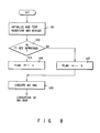
- Fig. 8 is a flowchart of the IRT routine in the second embodiment.
- the keyboard 36 is provided with a function key (F1) 36a for designating the change of the boot priority.
- the CPU 11 detects the depression of the F1 key 36a in the IRT routine. More specifically, the CPU 11 initializes and tests registers and devices in step 101. Then, the CPU 11 determines in step 103 whether or not the F1 key 36a is depressed. If the determination is affirmative, the CPU 11 sets a flag, i.e., sets logic "1" in the status register 59. Alternatively, if NO in step 103, the CPU 11 sets logic "0" in the specific register. Then, the CPU 11 executes the INT 19H in step 109.
- Figs. 19A and 19B show a flowchart of the INT 19H process.
- the reference numerals as in Figs.4A and 4B denote the same steps in Figs. 9A and 9B, and a detailed description thereof will be omitted.
- the CPU 11 determines in step 62 whether or not the flag (of the status register 59) is "0". If the flag is "0", it means that the "F1 key 36a is not depressed. Accordingly, the CPU 11 executes steps 63 to 79 which have been described with reference to Fig. 4A.
- step 62 determines whether the flag is "1" or "1"
- the CPU 11 executes the steps 81 to 93 shown in Fig. 9B.
- the CPU 11 determines in step 80 whether or not the flag is "0". If it is determined that the flag is "1", it means that the HDD boot is switched from the HDD boot mode to the normal boot mode. Thus, the CPU 11 executes steps 63 to 79 shown in Fig. 9A. On the contrary, if the determination in step 80 is affirmative, the change of boot priority is not caused. Therefore, the CPU 11 executes the steps 81 to 93 shown in Fig. 9B. As described above, in the second embodiment, when the system is powered while the F1 key 36a is being depressed, the normal boot priority is changed to the HDD boot priority or vice versa.
Abstract
Description
- The present invention relates to a personal computer having a plurality of bootstrap devices including a hard disk drive detachable to the personal computer.
- Compact, light-weight and low-cost personal computers have been developed. Such a personal computer is equipped with minimum function and other functions are optionally provided. There are many types of personal computers such as a type having a single floppy disk drive, a type having dual floppy disk drives, a type having a single floppy disk drive and a hard disk drive. In order to set up a system, a boot process is performed. More specifically, a CPU first reads the boot record of the floppy disk drive (FDD). If the CPU cannot read the boot record of the FDD, then reads the boot record of another FDD if present or reads the boot record of the hard disk drive (HDD) if the second FDD is not present. If the CPU can read the boot record of the FDD or the HDD, then it loads an operating system program stored in FDD or HDD. Thus, the system is set up.
- As described above, in the prior art, the boot priority is preliminarily fixed.
- Recently, a type having a detachable hard disk pack has been developed in order to further improve the portability. This type of personal computer is provided with a disk operating system (DOS) read only memory (ROM) (hereinafter referred to as DOS-ROM). The DOS-ROM has a similar format as the hard disk drive and stores a DOS file. More specifically, if the hard disk drive is not attached to the computer main body, the DOS-ROM serves as the hard disk drive. Accordingly, the device number "80H" is assigned to the HDD and the device number "81 H" may be assigned to the DOS-ROM in accordance with the specification of the industrial standard interface.
- However, if the device number "80H" is designated while the HDD is not attached and a device having the device number "81 H" is present, the boot process cannot be performed due to the constraint of the industrial standard DOS.
- An object of the present invention is to provide a personal computer having a plurality of bootstrap devices and which can execute the boot process in accordance with the boot priority preliminarily defined depending on the connection state of the bootstrap device.
- Another object of the present invention is to provide a personal computer having a function of quickly changing the boot priorities.
- According to a first aspect of the present invention, a personal computer comprises: a plurality of bootstrap devices, and at least one of the bootstrap devices being detachable to the personal computer; means for detecting the connection state of the detachable bootstrap device; means for preliminarily defining the boot priority order in response to the detection of the connection state of the detachable bootstrap device; and means for setting up the bootstrap devices in the order of the boot priorities.
- According to a second aspect of the present invention, a method for performing the boot process in a personal computer having a plurality of bootstrap devices, each of them having a different boot priority and one of them being a detachable type, comprises the computer steps of: a) detecting the connection of the detachable bootstrap device; and b) changing the boot priority of the bootstrap devices in response to the detection of the detachable bootstrap device.
- According to the present invention, when the system is powered, the CPU refers the flag during the execution of the IRT routine to recognize the connection state of the detachable hard disk pack. Different boot priorities are prefixed depending on the presence or absence of the hard disk pack. The bootstrap devices, namely, a floppy disk drive, a hard disk drive, and a DOS-ROM are set up in accordance with the boot priorities corresponding to the connection state of the hard disk pack.
- This invention can be more fully understood from the following detailed description when taken in conjunction with the accompanying drawings, in which:
- Fig. 1 is a system block diagram of a personal computer to which the boot priority changing apparatus of the present invention is applied;
- Fig. 2 is a flowchart showing an IRT routine to be executed by the personal computer shown in Fig. 1;
- Fig. 3 is a block diagram showing an arrangement for detecting the hard disk pack;
- Figs. 4A and 4B show a flowchart of a bootstrap process routine;
- Fig. 5 is a flowchart of an HDD function process;
- Fig. 6 is a flowchart of an FDD function process;
- Fig. 7 shows an example of a screen menu of a system setup;
- Fig. 8 is a flowchart showing an IRT routine of a second embodiment according to the present invention; and
- Figs. 9A and 9B show a flowchart of a bootstrap process routine in the second embodiment according to the present invention.
- Fig. 1 is a system block diagram of a personal computer to which the boot priority changing apparatus according to the present invention is applied.
- As shown in Fig. 1, the computer comprises a
system bus 10 andcomponents 11 to 28, and 51 connected to thebus 10. These components are: a main CPU (Central Processing Unit) 11, a basic input and output read only memory (BIOS-ROM) 12, a RAM (Random Access Memory) 13 serving as a main memory, a DMAC (Direct Memory Access Controller) 14, a PIC (Programmable Interrupt Controller) 15, a PIT (Programmable Interval Timer) 16, and a RTC (Real Time Clock) 17. - The main CPU (Central Processing Unit) 11 controls an entirety of the system, and executes the various routines represented by the flowcharts shown in Figs. 2, 3A and 3B, 4, 5, 7, 8A and 8B. The
main CPU 11 serves as a host CPU to thepower control CPU 306 incorporated in the power-supply circuit 30 to be described later. - The
ROM 12 stores a basic input and output program (BIOS). The BIOS includes the program shown in Figs. 2, 3A and 3B, 4, 5, 7, 8A and 8B. Themain CPU 11 executes the BIOS when the power switch of the computer is turned on to read the setup data stored in a specific area of the RAM 13 (or register) to determine the system environment, to further read a boot from a hard disk drive (HDD) 20A, and to load an disk operation system (DOS) program stored in theHDD 20A into theRAM 13. TheRAM 13 stores the DOS (Disk Operating System) program, application programs, and various data. Backup power VBX is supplied to theRAM 13 from the power-supply circuit 30. Hence, the data stored in theRAM 13 is not vanished even if the power switch of the computer is turned off. - The DMAC 14 performs a direct memory access control. The
PIC 15 can be set by a program. ThePIT 16 can be set by a program and supplies an interrupt signal to themain CPU 11 under control of thePIC 15 when its count reaches a value set by a program. In response to the interrupt signal, themain CPU 11 executes vector interrupt processing routine. TheRTC 17 is a timer module which has a dedicated built-in battery (not shown) and measures time; its output represents the present time. - As is shown in Fig. 1, the personal computer further comprises an
extended RAM 18, abackup RAM 19, ahard disk pack 20, a floppy disk controller (FDC) 20F, a printer controller (PRT-CONT) 21, an I/O interface 22, akeyboard controller 23, adisplay controller 24, avideo RAM 25, a DOS-ROM 26, and a power-supply interface 28 --all connected to thesystem bus 10. - The
extended RAM 18 is a large-capacity memory removably inserted in the card slot formed in one side of the main body of the personal computer, and the backup power VBK is supplied to theextended RAM 18. Thebackup RAM 19 is also supplied with the backup power VBX and keeps storing the data required to perform a resume function. Thehard disk pack 20 is removably set in a dedicated housing made in one side of the main body of the computer, and consists of, for example, a 2.5-inch hard disk drive (HDD) 20A and a hard disk controller (HDC) 20B. The floppy disk controller (FDC) 20F controls an external 3.5-inchfloppy disk drive 32 and a 5-inch externalfloppy disk drive 33. Theprinter controller 21 is connected to aprinter 34 externally connected to the computer. The I/O interface 22 is a universal asynchronous receiver/transmitter (UART). If necessary, RS-232C interface units are connected to the I/O interface 22. The keyboard controller (KBC) 23 controls the keyboard 36. The keyboard 36 is provided with alphanumeric keys and function keys including a F1 key 36a. The display controller (DISP-CONT) 24 controls a liquid crystal display (LCD) 37. The video RAM (VRAM) 25 is supplied with the backup power VBK and stores the video data. The DOS-ROM 26 has a similar format as thehard disk pack 20 and stores a disk operating system (DOS) program. The power-supply control interface (PS-IF) 28 connects the power-supply circuit 30 to themain CPU 11 through thesystem bus 10. - When necessary, an
AC adapter 29 is plugged into the main body of the personal computer. It rectifies the commercially available AC power into a DC power of a predetermined voltage. Anexpansion connector 40 is connected at one end to thesystem bus 10. An expansion unit is selectively connected to the other end of theconnector 40. The power-supply circuit 30 (an intelligent power supply) has a power control CPU (PC-CPU) 306. Amain battery 31A, which is a chargeable battery pack, is removably mounted on the main body of the personal computer. A sub-battery 31 B, which is also chargeable, is incorporated in the main body of the computer. - Fig. 2 is a flowchart showing an IRT (Initialize and Reliability Test) routine stored in the BIOS-ROM and executed when the system is powered.
- In
step 41, theCPU 11 sets the vector address ofINT 13H to start address of FDD function process shown in Fig. 6 as a default value. - In
step 43, theCPU 11 determines whether or not thehard disk pack 20 is connected. This determination is made by referring to astatus register 57. More specifically, as shown in Fig. 3, when thehard disk pack 20 is attached to the system main body, thelock mechanism 50 is operated to lock thehard disk pack 20 into the system main body. Theswitch 51 is actuated in cooperation with the operation of thelock mechanism 50. When thehard disk pack 20 is detached from the system main body, thelock mechanism 50 is released. Accordingly, the switch 53 is turned off in cooperation with the release operation. One terminal of switch 53 is connected to the ground and the other terminal thereof is connected to a specified pin of theconnector 55. The specified pin of theconnector 55 is connected to Vcc through a pull-upresistor 57. As a result, when thehard disk pack 20 is not connected to the system main body, the high level (logic "1") HDIN signal is output. When thehard disk pack 20 is attached to the system, a low level (logic "0") HDIN signal is output. The HDIN signal is stored in thestatus register 59. - In the determination of
step 43, if thehard disk pack 20 is attached to the computer main body, theCPU 11 sets the vector address ofINT 13H to a start address of a hard disk drive (HDD) function process shown in Fig. 5. Thereafter, theCPU 11 executes a process ofINT 19H (boot process). Note that both INT13H andINT 19H are a system call and a function request for calling a function of DOS. - Figs. 4A and 4B show a flowchart of the boot process of
INT 19H. Suppose now that thehard disk pack 20 is connected and thus the vector address ofINT 13H is directed toward the HDD function process. TheCPU 11 determines instep 61 whether or not the boot process is a normal boot or an HDD boot. This designation of the normal boot or the HDD boot is preliminarily designated in the system setup as shown in Fig. 7 and the setup data is stored in thebackup RAM 19. Therefore, theCPU 11 refers the backup RAM and determines the normal boot or the HDD boot. If the determination is the normal boot instep 61, theCPU 11 sets the device number "00" designating the floppy disk drive A in a specified register (DL register) and callsINT 13H. More specifically, in this case, since thehard disk pack 20 is connected, the vector address ofINT 13H is directed toward the HDD function process in Fig. 5. Therefore, theCPU 11 skips to and executes the HDD function process. TheCPU 11 determines instep 101 whether or not the device number is "80H" or not. Since in this case the device number is "00", theCPU 11 skips to and executes the FDD function process shown in Fig. 6. TheCPU 11 further determines instep 105 that the device number is not "80H", it executes the succeeding FDD function process. Thus, theCPU 11 reads, in thestep 63, boot record of floppy disk drive A (FDD A). (The boot record is stored incylinder 0,head 0, andsector 1.) Then, theCPU 11 determines instep 65 whether or not the boot record can be read out. If the boot record can be read out, theCPU 11 executes the boot process from the FDD A. More specifically, theCPU 11 loads the operating system program (OS) from the floppy disk drive A. - If the
CPU 11 cannot read the boot record from the FDD A, it reads, instep 67, the boot record of FDD B. TheCPU 11 sets the device number "01 designating the floppy disk drive B in the DL register and callsINT 13H. Similar to the case of floppy disk drive A, theCPU 11 executes the succeeding FDD function process passing through thesteps CPU 11 executes the boot process from the FDD B. - If the boot record can be read out neither from the FDD A nor from the FDD B, the
CPU 11 determines instep 71 that thehard disk pack 20 is connected. This determination is required in order to change the device number of the DOS-ROM 26. In this case, thehard disk pack 20 is connected. Therefore, the device number of the DOS-ROM 26 should be "81 H" since the device number "80H" is assigned to thehard disk pack 20. Thus theCPU 11 sets in the DL register "81 H" and callsINT 13H. Thus, theCPU 11 executes the HDD function process shown in Fig. 5. Since the content of the DL register is "81 H", the determination ofsteps CPU 11 executes the DOS-ROM function process. Accordingly, theCPU 11 reads instep 73 the boot record of the DOS-ROM 26. Then, theCPU 11 determines instep 75 whether or not the boot record can be read out. If the boot record can be read out instep 75, theCPU 11 loads the OS from the DOS-ROM 26 into themain memory 13. If the boot record cannot be read out instep 75, theCPU 11 executes an error process. - On the other hand, if the HDD boot is determined in
step 61, theCPU 11 determines instep 81 whether or not thehard disk pack 20 is connected to the computer. Since thehard disk pack 20 is connected, theCPU 11 executesstep 83. Instep 83, theCPU 11 sets in the DL register "80H" and callsINT 13H. Then, the CPU executes the HDD function process in Fig. 5. Since the determination ofstep 101 is affirmative, theCPU 11 determines instep 103 whether or not the device number is "81 H". Since the device number is "80H" in this case, theCPU 11 executes the succeeding HDD function. Accordingly, theCPU 11 reads instep 83 the boot record from thehard disk pack 20. If the read operation is successful instep 85, theCPU 11 executes the boot process from the hard disk pack. - If the read operation is not successful in
step 85, theCPU 11 sets in the DL register "81 H" and callsINT 13H. In this case, the determinations of bothsteps CPU 11 executes the succeeding DOS-ROM function process. Accordingly, theCPU 11 reads instep 87 the boot record from the DOS-ROM 26. If it is determined instep 89 that the read operation of thestep 87 is successful, theCPU 11 executes the boot process from the DOS-ROM 26. If the read operation is not successful instep 89, theCPU 11. executes the error process. - A case wherein the
hard disk pack 20 is not connected will now be described. - In this case, the vector address of
INT 13H is directed toward the FDD function process. Since the process ofsteps 63 to 69 is similar to those of the case wherein thehard disk pack 20 is connected, the description thereof will be omitted. - The
CPU 11 determines instep 71 that thehard disk pack 20 is not connected. Then, theCPU 11 sets in the DL register "80H" and callsINT 13H. As a result, theCPU 11 executesstep 105 in Fig. 6. Since the determination ofstep 105 is affirmative, theCPU 11 executes the DOS-ROM function process. Accordingly, theCPU 11 reads the boot record from the DOS-ROM 26. If the read operation of the boot record is successful, theCPU 11 executes the boot process from the DOS-ROM 26. - On the other hand, if the HDD boot is determined in
step 61, theCPU 11 determines instep 81 whether or not thehard disk pack 20 is connected. Since in this case, thehard disk pack 20 is not connected, theCPU 11 sets in the DL register "80H" and callsINT 13H. Then, theCPU 11 executes the FDD function process in Fig. 6. TheCPU 11 determines instep 105 that the device number is "80H" and therefore executes the DOS-ROM function process. Accordingly, theCPU 11 reads the boot record from the DOS-ROM 26. If the read operation of the boot record is successful, theCPU 11 executes the boot process from the DOS-ROM 26. - A second embodiment of the present invention will now be described with reference to Figs. 8, 9A and 9B.
- In the first embodiment, the boot priority is changed by designating the normal boot or the HDD boot on the system setup screen shown in Fig. 7. In the second embodiment, the boot priority can be quickly changed. Therefore, a DOS command must be input in order to display the screen shown in Fig. 7, and the system must be rebutted in order to change the boot mode.
- Fig. 8 is a flowchart of the IRT routine in the second embodiment. The keyboard 36 is provided with a function key (F1) 36a for designating the change of the boot priority. The
CPU 11 detects the depression of the F1 key 36a in the IRT routine. More specifically, theCPU 11 initializes and tests registers and devices instep 101. Then, theCPU 11 determines instep 103 whether or not the F1 key 36a is depressed. If the determination is affirmative, theCPU 11 sets a flag, i.e., sets logic "1" in thestatus register 59. Alternatively, if NO instep 103, theCPU 11 sets logic "0" in the specific register. Then, theCPU 11 executes theINT 19H instep 109. - Figs. 19A and 19B show a flowchart of the
INT 19H process. The reference numerals as in Figs.4A and 4B denote the same steps in Figs. 9A and 9B, and a detailed description thereof will be omitted. - The
CPU 11 determines instep 62 whether or not the flag (of the status register 59) is "0". If the flag is "0", it means that the "F1 key 36a is not depressed. Accordingly, theCPU 11 executessteps 63 to 79 which have been described with reference to Fig. 4A. - On the contrary, if it is determined in
step 62 that the flag is "1", it means that the boot priority is changed from the normal boot mode to the HDD boot mode. Therefore, theCPU 11 executes thesteps 81 to 93 shown in Fig. 9B. - On the other hand, if the determination is the HDD boot in
step 61, theCPU 11 determines instep 80 whether or not the flag is "0". If it is determined that the flag is "1", it means that the HDD boot is switched from the HDD boot mode to the normal boot mode. Thus, theCPU 11 executessteps 63 to 79 shown in Fig. 9A. On the contrary, if the determination instep 80 is affirmative, the change of boot priority is not caused. Therefore, theCPU 11 executes thesteps 81 to 93 shown in Fig. 9B. As described above, in the second embodiment, when the system is powered while the F1 key 36a is being depressed, the normal boot priority is changed to the HDD boot priority or vice versa.
Claims (8)
Applications Claiming Priority (4)
| Application Number | Priority Date | Filing Date | Title |
|---|---|---|---|
| JP295365/90 | 1990-11-02 | ||
| JP29536590A JPH04169929A (en) | 1990-11-02 | 1990-11-02 | Boot priority changing device |
| JP2340406A JPH04205627A (en) | 1990-11-30 | 1990-11-30 | Personal computer system |
| JP340406/90 | 1990-11-30 |
Publications (2)
| Publication Number | Publication Date |
|---|---|
| EP0483865A2 true EP0483865A2 (en) | 1992-05-06 |
| EP0483865A3 EP0483865A3 (en) | 1992-09-02 |
Family
ID=26560226
Family Applications (1)
| Application Number | Title | Priority Date | Filing Date |
|---|---|---|---|
| EP19910118646 Withdrawn EP0483865A3 (en) | 1990-11-02 | 1991-10-31 | Personal computer capable of changing boot priority |
Country Status (2)
| Country | Link |
|---|---|
| US (2) | US5274816A (en) |
| EP (1) | EP0483865A3 (en) |
Cited By (6)
| Publication number | Priority date | Publication date | Assignee | Title |
|---|---|---|---|---|
| EP0576027A2 (en) * | 1992-06-26 | 1993-12-29 | Kabushiki Kaisha Toshiba | Portable computer having menu selection function using icons |
| FR2693007A1 (en) * | 1992-06-26 | 1993-12-31 | Ela Medical Sa | Method for automatically installing a microprocessor system and corresponding system |
| WO1994019749A1 (en) * | 1993-02-26 | 1994-09-01 | Chou Benjamin E | Computer system for sharing common system resources with two or more independently operating microcomputers |
| GB2332076A (en) * | 1997-11-03 | 1999-06-09 | Iomega Corp | A computer recovery system provided on a removable high capacity disc |
| GB2349720A (en) * | 1999-01-25 | 2000-11-08 | Dell Usa Lp | Booting a computer system from one of two media |
| GB2379060A (en) * | 1997-11-03 | 2003-02-26 | Iomega Corp | Computer recovery system using removable high capacity media |
Families Citing this family (62)
| Publication number | Priority date | Publication date | Assignee | Title |
|---|---|---|---|---|
| US5799186A (en) * | 1990-12-20 | 1998-08-25 | Eastman Kodak Company | Method and apparatus for programming a peripheral processor with a serial output memory device |
| JPH05158664A (en) * | 1991-12-03 | 1993-06-25 | Canon Inc | Information processor |
| US5410713A (en) * | 1992-01-02 | 1995-04-25 | Smith Corona/Acer | Power-management system for a computer |
| US5471674A (en) * | 1992-02-07 | 1995-11-28 | Dell Usa, L.P. | Computer system with plug-in override of system ROM |
| FR2691556B1 (en) * | 1992-05-25 | 1994-08-26 | Hewlett Packard Co | Method and device for starting a computer at a scheduled time. |
| US5432939A (en) * | 1992-05-27 | 1995-07-11 | International Business Machines Corp. | Trusted personal computer system with management control over initial program loading |
| US5566335A (en) * | 1993-03-16 | 1996-10-15 | Hewlett-Packard Company | Method and apparatus for firmware upgrades in embedded systems |
| US5418918A (en) * | 1993-09-10 | 1995-05-23 | Compaq Computer Corp. | Scanning initial CD-ROM sectors for a boot record and executing said boot record to load and execute floppy disk image corresponding to the existing floppy drive |
| US6453363B1 (en) * | 1993-10-21 | 2002-09-17 | Microsoft Corporation | Method and computer system for integrating a compression system with an operating system |
| US5680556A (en) * | 1993-11-12 | 1997-10-21 | International Business Machines Corporation | Computer system and method of operation thereof wherein a BIOS ROM can be selectively locatable on diffeent buses |
| JP2812189B2 (en) * | 1994-02-10 | 1998-10-22 | 日本電気株式会社 | How to download the program |
| US5784611A (en) * | 1994-12-19 | 1998-07-21 | Seagate Technology, Inc. | Device and process for in-system programming electrically erasable and programmable non-volatile memory |
| US5715456A (en) * | 1995-02-13 | 1998-02-03 | International Business Machines Corporation | Method and apparatus for booting a computer system without pre-installing an operating system |
| US5860122A (en) * | 1995-11-14 | 1999-01-12 | Matsushita Electric Industrial Co., Ltd. | Backup unit including identifier conversion means |
| US5787491A (en) * | 1996-01-26 | 1998-07-28 | Dell Usa Lp | Fast method and apparatus for creating a partition on a hard disk drive of a computer system and installing software into the new partition |
| US5822582A (en) * | 1996-07-19 | 1998-10-13 | Compaq Computer Corporation | Boot drive selection and hibernation file detection |
| US5922072A (en) * | 1997-01-03 | 1999-07-13 | Ncr Corporation | Method and apparatus for creating alternate boot environments in a computer |
| US5905888A (en) * | 1997-02-19 | 1999-05-18 | On Spec Electronic, Inc. | Bootable redundant hard disk attached to a PC's parallel port with rom-address auto-detect and configure during BIOS scan |
| JPH10268958A (en) * | 1997-03-28 | 1998-10-09 | Toshiba Corp | Computer system and bootstrapping control method therefor |
| US5987548A (en) * | 1997-07-07 | 1999-11-16 | International Business Machines Corporation | Method and apparatus for determining system identification number system using system data bus and pull-up resistors in combination with a sensing circuitry |
| US6061788A (en) * | 1997-10-02 | 2000-05-09 | Siemens Information And Communication Networks, Inc. | System and method for intelligent and reliable booting |
| US6356965B1 (en) * | 1998-09-08 | 2002-03-12 | Compaq Computer Corporation | Hotkey for network service boot |
| US6282641B1 (en) | 1998-11-18 | 2001-08-28 | Phoenix Technologies Ltd. | System for reconfiguring a boot device by swapping the logical device number of a user selected boot drive to a currently configured boot drive |
| US6385721B1 (en) | 1999-01-22 | 2002-05-07 | Hewlett-Packard Company | Computer with bootable hibernation partition |
| US6715043B1 (en) | 1999-03-19 | 2004-03-30 | Phoenix Technologies Ltd. | Method and system for providing memory-based device emulation |
| US6519659B1 (en) | 1999-06-18 | 2003-02-11 | Phoenix Technologies Ltd. | Method and system for transferring an application program from system firmware to a storage device |
| US6578142B1 (en) | 1999-06-18 | 2003-06-10 | Phoenix Technologies, Ltd. | Method and apparatus for automatically installing and configuring software on a computer |
| US6473855B1 (en) | 1999-06-18 | 2002-10-29 | Phoenix Technologies Ltd. | Method and apparatus for providing content on a computer system based on usage profile |
| US6373498B1 (en) | 1999-06-18 | 2002-04-16 | Phoenix Technologies Ltd. | Displaying images during boot-up and shutdown |
| US6486883B1 (en) | 1999-06-18 | 2002-11-26 | Phoenix Technologies, Ltd. | Apparatus and method for updating images stored in non-volatile memory |
| US6405309B1 (en) | 1999-06-18 | 2002-06-11 | Phoenix Technologies Ltd. | Method and apparatus for creating and deploying smaller Microsoft Windows applications for automatic configuration of a computing device |
| US6542160B1 (en) | 1999-06-18 | 2003-04-01 | Phoenix Technologies Ltd. | Re-generating a displayed image |
| US6401202B1 (en) | 1999-06-18 | 2002-06-04 | Phoenix Technologies Ltd. | Multitasking during BIOS boot-up |
| US6457122B1 (en) | 1999-06-18 | 2002-09-24 | Phoenix Technologies Ltd. | Fault tolerant process for the delivery of programs to writeable storage device utilizing pre-operating system software/firmware |
| US6449682B1 (en) | 1999-06-18 | 2002-09-10 | Phoenix Technologies Ltd. | System and method for inserting one or more files onto mass storage |
| US6453469B1 (en) | 1999-06-18 | 2002-09-17 | Phoenix Technologies Ltd. | Method and apparatus to automatically deinstall an application module when not functioning |
| US6438750B1 (en) | 1999-06-18 | 2002-08-20 | Phoenix Technologies Ltd. | Determining loading time of an operating system |
| US6477642B1 (en) | 1999-06-18 | 2002-11-05 | Phoenix Technologies Ltd. | Method and apparatus for extending BIOS control of screen display beyond operating system boot process |
| KR100343191B1 (en) * | 1999-09-30 | 2002-07-10 | 구자홍 | Method for booting a computer |
| US6553432B1 (en) * | 1999-10-26 | 2003-04-22 | Dell Usa, L.P. | Method and system for selecting IDE devices |
| KR100319292B1 (en) * | 1999-12-02 | 2002-01-05 | 윤종용 | Computer system and method for quickly booting |
| US6487656B1 (en) | 1999-12-10 | 2002-11-26 | Phoenix Technologies Ltd. | System and method for providing functionalities to system BIOS |
| US6721883B1 (en) | 2000-01-25 | 2004-04-13 | Dell Usa, L.P. | System and method for managing the boot order of a computer system |
| US6990685B1 (en) | 2000-06-15 | 2006-01-24 | Dell Products L.P. | System and method for tracking bootable devices |
| JP2002063042A (en) * | 2000-08-21 | 2002-02-28 | Nec Microsystems Ltd | Program module management system, management method therefor and recording medium with its management program recorded on the same |
| US6754818B1 (en) * | 2000-08-31 | 2004-06-22 | Sun Microsystems, Inc. | Method and system for bootstrapping from a different boot image when computer system is turned on or reset |
| US6725294B1 (en) * | 2001-02-20 | 2004-04-20 | Lsi Logic Corporation | Installation and access of a device handler for a peripheral device in a computer |
| US7080245B2 (en) * | 2002-05-23 | 2006-07-18 | Hewlett-Packard Development Company, L.P. | Method and system of switching between two or more images of firmware on a host device |
| US6988194B2 (en) * | 2002-06-13 | 2006-01-17 | Dell Products L.P. | System and method for preserving boot order in an information handling system when a boot device is replaced by a matching device |
| US20040128492A1 (en) * | 2002-12-27 | 2004-07-01 | Mitac Technology Corp. | Memory device for assistant execution of computer program in semi-opening or all-opening machine |
| TWI220497B (en) * | 2003-03-07 | 2004-08-21 | Novatek Microelectronics Corp | Data processing system having built-in memory in micro-processor |
| KR100924776B1 (en) * | 2003-04-23 | 2009-11-03 | 삼성전자주식회사 | Hybrid device able to meditate priority of task-handler and user interface thereof |
| US7174446B2 (en) * | 2003-04-25 | 2007-02-06 | Dell Products L.P. | System and method for managing the boot sequence of an information handling system |
| US7391963B2 (en) * | 2003-09-29 | 2008-06-24 | Inventec Corporation | Method of controlling multimedia audio and video playback |
| US7234055B2 (en) * | 2004-08-24 | 2007-06-19 | Inventec Corporation | Computer operating booting system making use of multi-buttons |
| JP4671332B2 (en) * | 2005-03-10 | 2011-04-13 | 株式会社日立製作所 | File server that converts user identification information |
| US7779242B2 (en) * | 2005-12-22 | 2010-08-17 | International Business Machines Corporation | Data processing system component startup mode controls |
| TWI310157B (en) * | 2006-02-23 | 2009-05-21 | Asustek Comp Inc | Method for changing booting source of a computer system and related backuping/restoring method thereof |
| US8214541B2 (en) * | 2006-06-07 | 2012-07-03 | Dell Products L.P. | Method and system for uniquely identifying peripheral component devices |
| US8285977B2 (en) * | 2007-10-24 | 2012-10-09 | Dell Products L.P. | System and method for extension of the BIOS boot specification |
| US8699220B2 (en) | 2010-10-22 | 2014-04-15 | Xplore Technologies Corp. | Computer with removable cartridge |
| CN107357400B (en) * | 2016-05-10 | 2021-03-26 | 佛山市顺德区顺达电脑厂有限公司 | Method for automatically starting up hard disk with specified operating system type |
Citations (2)
| Publication number | Priority date | Publication date | Assignee | Title |
|---|---|---|---|---|
| EP0364115A2 (en) * | 1988-10-14 | 1990-04-18 | Compaq Computer Corporation | Dynamically configurable portable computer system |
| WO1990006554A1 (en) * | 1988-11-30 | 1990-06-14 | Laboratoire Europeen De Recherches Electroniques Avancees | Computer and starting-up process of said computer |
Family Cites Families (2)
| Publication number | Priority date | Publication date | Assignee | Title |
|---|---|---|---|---|
| US5210875A (en) * | 1989-08-25 | 1993-05-11 | International Business Machines Corporation | Initial bios load for a personal computer system |
| US5128995A (en) * | 1990-07-23 | 1992-07-07 | International Business Machines Corp. | Apparatus and method for loading a system reference diskette image from a system partition in a personal computer system |
-
1991
- 1991-10-31 EP EP19910118646 patent/EP0483865A3/en not_active Withdrawn
- 1991-11-01 US US07/786,795 patent/US5274816A/en not_active Expired - Lifetime
-
1994
- 1994-06-17 US US08/261,876 patent/US5448741A/en not_active Expired - Lifetime
Patent Citations (2)
| Publication number | Priority date | Publication date | Assignee | Title |
|---|---|---|---|---|
| EP0364115A2 (en) * | 1988-10-14 | 1990-04-18 | Compaq Computer Corporation | Dynamically configurable portable computer system |
| WO1990006554A1 (en) * | 1988-11-30 | 1990-06-14 | Laboratoire Europeen De Recherches Electroniques Avancees | Computer and starting-up process of said computer |
Cited By (15)
| Publication number | Priority date | Publication date | Assignee | Title |
|---|---|---|---|---|
| EP0576027A2 (en) * | 1992-06-26 | 1993-12-29 | Kabushiki Kaisha Toshiba | Portable computer having menu selection function using icons |
| FR2693007A1 (en) * | 1992-06-26 | 1993-12-31 | Ela Medical Sa | Method for automatically installing a microprocessor system and corresponding system |
| EP0578530A1 (en) * | 1992-06-26 | 1994-01-12 | Ela Medical | Method for automatic initialisation of a microprocessor system and corresponding system |
| EP0576027A3 (en) * | 1992-06-26 | 1995-02-01 | Tokyo Shibaura Electric Co | Portable computer having menu selection function using icons. |
| US5537531A (en) * | 1992-06-26 | 1996-07-16 | Kabushiki Kaisha Toshiba | Portable computer with a bank switch for switching between a ROM and a memory, both allocated to the same address space, by changing a port address of a keyboard controller |
| WO1994019749A1 (en) * | 1993-02-26 | 1994-09-01 | Chou Benjamin E | Computer system for sharing common system resources with two or more independently operating microcomputers |
| GB2332076A (en) * | 1997-11-03 | 1999-06-09 | Iomega Corp | A computer recovery system provided on a removable high capacity disc |
| US6317845B1 (en) | 1997-11-03 | 2001-11-13 | Iomega Corporation | System for computer recovery using removable high capacity media |
| GB2379060A (en) * | 1997-11-03 | 2003-02-26 | Iomega Corp | Computer recovery system using removable high capacity media |
| GB2332076B (en) * | 1997-11-03 | 2003-03-05 | Iomega Corp | System for computer recovery using removable high capacity media |
| GB2379060B (en) * | 1997-11-03 | 2003-04-09 | Iomega Corp | System for computer recovery using removable high capacity media |
| GB2349720A (en) * | 1999-01-25 | 2000-11-08 | Dell Usa Lp | Booting a computer system from one of two media |
| GB2349720B (en) * | 1999-01-25 | 2001-12-19 | Dell Usa Lp | System and method for initiating operation of a computer system |
| US6347371B1 (en) | 1999-01-25 | 2002-02-12 | Dell Usa, L.P. | System and method for initiating operation of a computer system |
| SG88755A1 (en) * | 1999-01-25 | 2002-05-21 | Dell Usa Lp | System and method for initiating operation of a computer system |
Also Published As
| Publication number | Publication date |
|---|---|
| EP0483865A3 (en) | 1992-09-02 |
| US5448741A (en) | 1995-09-05 |
| US5274816A (en) | 1993-12-28 |
Similar Documents
| Publication | Publication Date | Title |
|---|---|---|
| EP0483865A2 (en) | Personal computer capable of changing boot priority | |
| KR930012128B1 (en) | Personal computer | |
| US5768568A (en) | System and method for initializing an information processing system | |
| US5021983A (en) | Suspend/resume apparatus and method for reducing power consumption in battery powered computers | |
| CN100359434C (en) | Information processor, starting method thereof | |
| US5276890A (en) | Resume control system and method for executing resume processing while checking operation mode of CPU | |
| US6832311B2 (en) | Information processing system and resume processing method used in the system | |
| KR100281525B1 (en) | Computer system with automatic detection | |
| US5339444A (en) | Portable computer resetting resume error caused from HDD loaded condition being changed and starting OS | |
| JPH0744286A (en) | Computer system with multilevel power-supply control | |
| US5469565A (en) | Personal computer for disabling resume mode upon replacement of HDD | |
| EP0658843A1 (en) | Method for hibernation file creation | |
| KR950001418B1 (en) | Pop up control system for portable computer having setup function and popup function | |
| JPH09120385A (en) | Prevention method for loss of device configuration on standby in computer system and controller circuit for capturing of device configuration | |
| US20060212550A1 (en) | Information processing apparatus and activation method | |
| US6154846A (en) | System for controlling a power saving mode in a computer system | |
| US5432938A (en) | Method and system for controlling resume process in computer unit capable of connecting expansion unit | |
| US6892263B1 (en) | System and method for hot swapping daughtercards in high availability computer systems | |
| AU634114B2 (en) | Computer having function of resume process | |
| JP3437238B2 (en) | Computer, computer system and control method thereof | |
| EP0429781B1 (en) | Resume control system and method for executing resume processing while checking operation mode of CPU | |
| KR100568246B1 (en) | Computer System And Controlling Method Thereof | |
| JPH0527860A (en) | Portable computer | |
| KR0130785Y1 (en) | Card exchange detecting device | |
| KR950003133B1 (en) | Memory refresh control system upon connection of extension unit |
Legal Events
| Date | Code | Title | Description |
|---|---|---|---|
| PUAI | Public reference made under article 153(3) epc to a published international application that has entered the european phase |
Free format text: ORIGINAL CODE: 0009012 |
|
| 17P | Request for examination filed |
Effective date: 19911127 |
|
| AK | Designated contracting states |
Kind code of ref document: A2 Designated state(s): DE FR GB |
|
| PUAL | Search report despatched |
Free format text: ORIGINAL CODE: 0009013 |
|
| AK | Designated contracting states |
Kind code of ref document: A3 Designated state(s): DE FR GB |
|
| 17Q | First examination report despatched |
Effective date: 19961122 |
|
| STAA | Information on the status of an ep patent application or granted ep patent |
Free format text: STATUS: THE APPLICATION IS DEEMED TO BE WITHDRAWN |
|
| 18D | Application deemed to be withdrawn |
Effective date: 19970403 |