EP0484076A2 - Video camera having focusing and image-processing function - Google Patents
Video camera having focusing and image-processing function Download PDFInfo
- Publication number
- EP0484076A2 EP0484076A2 EP91309926A EP91309926A EP0484076A2 EP 0484076 A2 EP0484076 A2 EP 0484076A2 EP 91309926 A EP91309926 A EP 91309926A EP 91309926 A EP91309926 A EP 91309926A EP 0484076 A2 EP0484076 A2 EP 0484076A2
- Authority
- EP
- European Patent Office
- Prior art keywords
- image
- image pickup
- pickup element
- video camera
- foe
- Prior art date
- Legal status (The legal status is an assumption and is not a legal conclusion. Google has not performed a legal analysis and makes no representation as to the accuracy of the status listed.)
- Granted
Links
Images


Classifications
-
- H—ELECTRICITY
- H04—ELECTRIC COMMUNICATION TECHNIQUE
- H04N—PICTORIAL COMMUNICATION, e.g. TELEVISION
- H04N25/00—Circuitry of solid-state image sensors [SSIS]; Control thereof
- H04N25/48—Increasing resolution by shifting the sensor relative to the scene
-
- H—ELECTRICITY
- H04—ELECTRIC COMMUNICATION TECHNIQUE
- H04N—PICTORIAL COMMUNICATION, e.g. TELEVISION
- H04N23/00—Cameras or camera modules comprising electronic image sensors; Control thereof
- H04N23/58—Means for changing the camera field of view without moving the camera body, e.g. nutating or panning of optics or image sensors
-
- H—ELECTRICITY
- H04—ELECTRIC COMMUNICATION TECHNIQUE
- H04N—PICTORIAL COMMUNICATION, e.g. TELEVISION
- H04N23/00—Cameras or camera modules comprising electronic image sensors; Control thereof
- H04N23/60—Control of cameras or camera modules
- H04N23/67—Focus control based on electronic image sensor signals
- H04N23/673—Focus control based on electronic image sensor signals based on contrast or high frequency components of image signals, e.g. hill climbing method
-
- H—ELECTRICITY
- H04—ELECTRIC COMMUNICATION TECHNIQUE
- H04N—PICTORIAL COMMUNICATION, e.g. TELEVISION
- H04N23/00—Cameras or camera modules comprising electronic image sensors; Control thereof
- H04N23/60—Control of cameras or camera modules
- H04N23/67—Focus control based on electronic image sensor signals
- H04N23/676—Bracketing for image capture at varying focusing conditions
-
- H—ELECTRICITY
- H04—ELECTRIC COMMUNICATION TECHNIQUE
- H04N—PICTORIAL COMMUNICATION, e.g. TELEVISION
- H04N23/00—Cameras or camera modules comprising electronic image sensors; Control thereof
- H04N23/70—Circuitry for compensating brightness variation in the scene
- H04N23/743—Bracketing, i.e. taking a series of images with varying exposure conditions
Definitions
- the present invention relates to a video camera and, more particularly, to a video camera having an improved "auto-focus scheme", capable of obtaining an in-focus image of an object moving at high speed, and having a image-processing function for the in-focus image.
- the active scheme emits, e.g., an ultrasonic wave or an infrared ray and receives the wave or ray reflected by an object.
- the passive scheme determines an object distance in accordance with only a video signal.
- a technique for detecting a moving object from instantaneously changing scenes obtained by a moving image pickup system is required.
- a still image of an environment is picked up as a background image. Differences between this background image and time-serially obtained images are sequentially obtained, and a total sum of change amounts in a predetermined area is obtained. The total sum is compared with a threshold value to decide "intrusion" within the field of view.
- the optical flow in a target area is obtained from a time-serial image, and the background area is separated from the intrusion object on the basis of the optical flow, thereby performing highly reliable detection.
- Extensive studies have been made for a fundamental technique in this scheme as motion analysis in the fields of computer visions since late 1970.
- the techniques conventionally subjected to the above extensive studies are classified into a "gradient-based technique” using spatial and time changes in image densities and a “feature-based technique” for extracting features (characteristics) such as edges from an image and estimating a movement amount from a correlation result between the corresponding features in images having a time difference.
- the former technique has an advantage in that a movement amount with respect to an image as a whole can be obtained.
- precision is greatly degraded by noise mixture in an image.
- estimated values for a coarse texture area and a boundary object area become inaccurate.
- the latter scheme has inaccurate movement amounts because feature values are used.
- degradation of precision by noise can be minimized in the latter technique.
- the gist of the present invention will be as follows.
- the image pickup element is always vibrated along the optical axis to perform image pickup operations at a plurality of arbitrary positions (i.e., intermediate positions within the amplitude of the vibration), and at least one image whose focal points are matched is obtained from the plurality of images obtained by the above image pickup operations, thereby extracting and visualizing its clear image.
- the video camera comprises an image pickup element, having an auto-focus function, for picking up an optical image obtained through a lens system, means for vibrating the lens system or the image pickup element at a predetermined period in a direction of an optical axis, and for causing the image pickup element to perform image pickup operations at a plurality of arbitrary positions, and means for extracting a predetermined image signal from the plurality of image signals of different focal positions obtained by the image pickup element.
- the means for extracting the predetermined image signal employs the following techniques:
- the vibration period of the image pickup element is preferably synchronized with a frame period of an image signal.
- a piezoelectric actuator is more preferable as a drive source for driving the image pickup element than a motor.
- the video camera according to the present invention is arranged as its application in the following manner.
- the camera comprises means for picking up an optical image obtained through a lens system, means for vibrating a lens or an image pickup element at a predetermined period in a direction of an optical axis and for causing the image pickup element to perform image pickup operations at arbitrary positions, means for extracting an optical flow from a plurality of images obtained from the image pickup element, and means for detecting a moving object by using the optical flow, wherein time-serial images obtained by linearly vibrating the image pickup element or the lens in the direction of the optical axis are accumulated, an optical flow between the accumulated time-serial images is obtained, and motion vector strings obtained by connecting the corresponding vectors are separated into motion vector strings having FOE (Focus Of Expansion) points by the above vibration and motion vector strings without FOE points, thereby detecting an intrusion object.
- FOE Full-Focus Of Expansion
- image pickup operations are performed while the image pickup element is always vibrated along the optical axis.
- Video signals obtained in the vibrated state of the image pickup element are processed in accordance with a predetermined sequence. Therefore, "high-speed focusing" operations can be performed, and at the same time, an image having a wider focal range from the infinite position to the closest position (i.e., a wide range in the direction of the depth of field of the object) can be obtained.
- An image signal is sampled at a plurality of arbitrary points during movement of the image pickup element, and only an image having highest in-focus precision is output and visualized.
- predetermined image processing is performed while the vibration period of the image pickup element is synchronized with the frame period of the image signal, thereby always obtaining an in-focus motion image.
- the technique for processing the sampled images is changed to obtain an in-focus image in the wider range from the infinite position to the closest position.
- the vibration period of the image pickup element is synchronized with the frame period of the image signal so that the image reception positions are set identical to each other.
- Electronic auto-focus control is performed while the image reception positions or its setup are synchronized with the focus signals, thereby always obtaining an in-focus motion image.
- images are input while the lens or the image pickup element is vibrated to obtain time-serial images having small time and positional differences.
- "correlation search" can be easily performed.
- the highly precise optical flow can be obtained although this cannot be obtained by images picked up by the conventional image pickup element.
- vibration linearity can be precisely controlled, so that precision of FOE measurement can be improved. Therefore, the background can be separated from the motion of the moving object, thereby obtaining a highly precise image.
- a lens system 10 comprises a focusing lens 11 which is used in focusing but is not moved in zooming, a zoom lens 12 moved to change the size of an image formed by the focusing lens 11, a focal position correction lens 13 called a "compensator" moved to maintain an image formation position constant, and a relay lens or condenser lens 14.
- a zoom lens 12 moved to change the size of an image formed by the focusing lens 11
- a focal position correction lens 13 called a "compensator” moved to maintain an image formation position constant
- a relay lens or condenser lens 14 moved to maintain an image formation position constant
- Each of these lenses 11 to 14 comprises a plurality of lenses.
- the lens system 10 comprise four groups of lenses.
- a low-pass filter 15 is located behind the lens system 10.
- An image pickup element 20 is located behind the low-pass filter 15 to pick up an optical image.
- Optical information of an object to be photographed or the like is incident on the image pickup element 20 through the lens system 10 and is picked up (photo-electrically) by the image pickup element 20.
- the image pickup element 20 is always vibrated with a stroke (amplitude) of about 3 mm in a direction of an optical axis by a vibration generation system 100 including a piezoelectric actuator 70.
- This stroke value is a value required to perform focusing upon movement of the image pickup element from the infinite position to the closest position of 1 m in an 1/2 ⁇ optical system with zooming having a magnification of 6.
- a position x ⁇ of the image pickup element 20 corresponding to a distance ⁇ to the object is assumed to represent a position of the image pickup element closest to the lens system 10.
- a position xlm of the image pickup element 20 corresponding to a distance of 1m to the object is assumed to represent a position of the image pickup element 20 farthest from the lens system 10.
- the image pickup element 20 is vibrated between the above two points (stroke) to obtain a plurality of image signals.
- a plurality of time-serial image signals obtained by the image pickup element 20 are input to an image input system 200 for sequentially processing these plurality of image signals.
- Each input image signal is input to an image signal processing circuit 22 connected to the image pickup element 20 and is subjected to processing such as A/D conversion. Thereafter, the precessed image signal is temporarily stored in an image field (i.e., frame) memory 35 (in units of time-serial signals).
- In-focus states of the plurality of converted image signals are detected by an in-focus decision circuit 24 connected to the image signal processing circuit 22 in units of images.
- the clearest image is selected from the plurality of image signals as a result of this detection. Desired images are partially extracted by, e.g., an image synthesizing circuit 26, as needed, and are synthesized as one image in an output image memory 60 by synthesis processing. The synthesized image is finally displayed and output on a screen 80.
- a motor 50 in Fig. 1 constitutes an auto-zoom mechanism for driving the zoom lens 12 through a pinion and a worm gear in the direction of the optical axis to change a focal length.
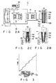
- FIG. 2A A normal operating shape of the piezoelectric actuator 70 is shown in Fig. 2A, and deformed shapes during its operations are shown in Figs. 2B and 2C.
- a predetermined control signal having a magnitude falling with the range of qV is applied from an actuator control circuit 73 to the piezoelectric actuator 70 to always vibrate the image pickup element 20 in the direction of the optical axis in Figs. 2A to 2C.
- the stroke (vibration) of the piezoelectric actuator 70 is about 3 mm with respect to the object in the range from the infinite position to the closest position of 1 m in the 1/2 ⁇ optical system with zooming having a magnification of 6.
- the image pickup element 37 obtains images of object positions corresponding to positions within this stroke. These image signals are supplied (input) to the image input circuit system 200.
- the lens system 10 comprises 4 lens groups consisting of the focusing lens 11, the zoom lens 12, the focal position correction lens 13, and the relay lens 14.
- the low-pass filter 15 is located behind the lens system 10.
- An optical image is formed on the image pickup plane of the image pickup element 20 such as a CCD through the lens system 10 and the low-pass filter 15.
- the piezoelectric actuator 70 is mounted on the side of the image pickup element 20 opposite to its image pickup plane to move the image pickup element 20 in the direction of the optical axis.
- the piezoelectric actuator 70 comprise S-shaped driven bimorph elements 71a to 71f. These S-shaped driven bimorph elements are elements driven so that displacement directions of each bimorph element have opposite phases with respect to the center along the longitudinal direction.
- two structures each consisting of three S-shaped driven bimorph elements (71a to 71c or 71d to 71f) connected in series with each other constitute cantilevered bimorph structures. When free ends of these two cantilevered bimorph are connected, the displacement is increased and the mechanical characteristics are improved.
- Another pair of cantilevered bimorph structures are prepared as in the bimorph elements 71a to 71f, as indicated by the alternate long and two short dashed lines, thereby further improving the mechanical characteristics.
- a graph in Fig. 3 shows an operation of a "high-speed focusing" operation.
- Axial movement of the image pickup element 20 is represented by a polygonal line.
- the position x of the image pickup element (range: infinite to 1 m) is plotted along the abscissa of this graph, and time t (required to obtain an infocus state) is plotted along the ordinate.
- a plurality of images corresponding to a plurality of arbitrary positions are sampled within the movement range of the image pickup element 20.
- the image pickup element 20 performs sampling several times (5 times in this embodiment).
- Driving of the image pickup element 20 by the movement actuator is set so that the image pickup element is stopped for a sampling (predetermined) time or more. Note that if the sampling (predetermined) time is sufficiently shorter than the movement time of the image pickup element 20, the stop time need not be provided.
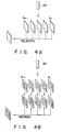
- a plurality (five in this embodiment) of images are obtained during sampling between x ⁇ to xlm.
- High-frequency components of the image signals of these images are extracted and integrated to detect "focal point evaluation values" for detecting the degrees of focusing (i.e., focusing precision: in-focus precision).
- Comparison is performed in units of images. Of these images, one image having highest in-focus precision is selected and is output as an image. More specifically, the vibration period of the image pickup element 20 is synchronized with the frame period of the image signal.
- NTSC National Television System Committee
- a video camera as an imaging apparatus suitable for an application in which an in-focus image is obtained on the entire screen if so desired further comprises the image synthesizing circuit 26 for performing image synthesis processing.
- the image synthesizing circuit 26 divides each sampling image into a plurality of areas, as shown in Fig. 4B, and focus detection is performed in units of divided areas.
- focus detection is performed in units of divided areas.
- only in-focus areas are extracted from the memory 35 to synthesize them into one image. Therefore, an image (e.g., a motion image) having an extremely large depth of field, i.e., an in-focus image in the entire range from the infinite position to the closest position can be obtained.
- filtering processing for filtering a blur portion in each image or an “omission and synthesis technique” for omitting blur portions of the images and synthesizing the resultant images may be employed.
- the image pickup element 20 is vibrated in synchronism with the frame period of the image signal.
- the reception time of the image signal forming one frame is set sufficiently shorter than the vibration period, and only image signals at given focal positions within the vibration range are read. Since the vibration period coincides with the frame period, the read position can be electronically and arbitrarily controlled. A focal point evaluation value is detected from the read image signal, and the read position is fed back, thereby performing auto-focus processing. Since the auto-focus feedback system can be constituted by only electronic circuits, in-focus motion images can always be obtained.
- the image signals obtained during movement between two points falling within the range of x ⁇ and xlm are received and displayed. For example, when a display operation is performed every 30 frames/sec as in the NTSC scheme, an image is obtained such that images overlap from an image of the closest position to an image of the infinite position. Although image quality is slightly degraded, this scheme can provide an in-focus image in a wide range from the infinite position to the closest position. Therefore, a clear object having a high contrast level can be sufficiently recognized. A better image can be obtained when image processing is performed.
- the above description exemplifies a technique for obtaining an in-focus image within a field.
- the image pickup element 20 need not be operated at very high speed (e.g., vibration in this case), and any scheme may be employed if an appropriate in-focus image is obtained by simpler processing.
- the image pickup element 20 is vibrated.
- a lens system such as a focus control lens (correction lens 13) is similarly driven.
- the means for vibrating the image pickup element 20 or the lens system 10 is not limited to the piezoelectric actuator 70, but may be replaced with another means such as a voice coil motor.
- the above embodiment according to the present invention can cope with an object or the like which is moving at high speed in a wider range of the depth of field, which operation has not been made by a conventional video camera with an auto-focus mechanism. There is therefore realized a video camera having a high focusing speed capable of obtaining an in-focus image at a higher speed in accordance with predetermined image processing.
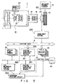
- a video camera body 1 shown in Fig. 5 is combined with the vibration generation system and is used in an image surveillance apparatus such as an intrusion surveillance camera according to the second embodiment of the present invention.
- image surveillance apparatuses are applied to intrusion detection in department stores and offices and obstacle detection in moving robots.
- This embodiment aims at providing an image surveillance video camera which utilizes the gist of the present invention that "a lens or image pickup element of a camera or the like is vibrated at a predetermined period in a direction of an optical axis to input instantaneous images, thereby acquiring time-serial images having small time and positional differences". More specifically, by obtaining a highly reliable "optical flow" coping with an object moving at high speed which cannot be captured by zooming in an image of a conventional image pickup apparatus such as a video camera, the background can be separated from motion of the moving object in an image, thereby providing an image surveillance apparatus for easily obtaining a high-quality (i.e., in-focus) image.
- the video camera body 1 is a combination of an image pickup element 20 and a vibration generation system 100 for moving the element itself or part or all of a lens system 10 with a predetermined amplitude at a predetermined period in the direction of the optical axis.
- This vibration generation system 100 comprises a piezoelectric actuator 70, an actuator control circuit 73, and a drive circuit (not shown).
- An image output corresponding to a half cycle of the vibration period is sequentially transferred to an image input system 200 connected to the image pickup element 20.
- the image input system 200 performs predetermined image processing (details will be described with reference to Fig. 6) such as digital conversion of the image output.
- the processed image output is stored in an image memory 35 (in units of time-serial signals) through an image information bus 8.
- an optical flow detector system 300 an FOE measuring circuit system 400, an intrusion decision circuit 500, and an optical flow memory 65, all of which are associated with surveillance processing (to be described in detail later) are connected in parallel with a control bus 9 connected to a CPU 90 for controlling the overall operation of the apparatus.
- the optical flow detector system 300 connected to the control bus 9 and the image bus 8 obtains "motion" associated with a corresponding area from a plurality of time-serial images prestored in the image memory 35 in accordance with predetermined analysis processing and detects an "optical flow” of this area.
- An FOE detector 4 analyzes the "motions" of the background and the object to measure an FOE (Focus Of Expansion) point where the optical flow of the stationary object obtained upon movement of an image pickup plane along the direction of the optical axis is generated.
- the intrusion decision circuit 500 decides whether the optical flow contains components which are not generated from the FOE point, thereby detecting "intrusion” of, e.g., an object moving into the field of view of the intrusion surveillance camera.
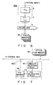
- Fig. 6 shows the image input system 200 and the associated image memory (field memories) 35 connected thereto through the image bus 8.
- the arrangement of the image input system 200 will be as follows.
- An image signal output from the camera body 1 is converted into a digital signal by an A/D converter 6.
- the digital signal is stored in the image memory 35 through an ITV interface 7 and the image bus 8.
- the image memory (e.g., field memories) 35 is also connected to the control bus 9, so that random read/write access can be performed.
- a plurality of images i.e., time-serial images
- a half cycle i.e., a forward stroke of the image pickup plane position toward the lenses
- Fig. 7 shows an arrangement of the FOE measuring circuit system 400.
- the optical flow of the stationary object obtained upon movement of the image pickup plane in the direction of the optical image is a flow generated from one point. This point is called the FOE.
- the optical flow of the stationary environment is obtained in advance, and a line detecting circuit 42 obtains linear expressions from "motion vector strings" obtained by connecting the corresponding areas. These linear expressions can be derived using the method of least squares method.
- An FOE calculation circuit 44 obtains intersections of the respective lines to calculate FOE coordinates. For example, if three or more straight lines (e.g., segments) are obtained, the center of gravity of these intersections is set as the FOE point (position).
- the FOE coordinates are stored in an FOE memory 46.
- Fig. 8 shows an arrangement of the optical flow detector system 300.
- the following processing will be performed to analyze image features, similarity points between a plurality of images, and the like.
- a characteristic area selection circuit 32 selects a target area for calculating motion vectors from the image of the previous moment (i.e., the image located behind the image pickup plane). Parameters such as an area size and a maximum area count are prestored in a characteristic memory 36. Character (feature) area decision processing is realized by calculating a "variance value" inside the area and selecting an area having a value larger than a predetermined threshold value supplied to the characteristic memory 36.
- a similarity calculating circuit 34 searches the image of the next moment (i.e., the image located in front of the image pickup plane) and selects an area having most similar "density characteristics" in the respective characteristic areas.
- the range of search is preset in a similarity memory 38. In practice, however, the range of search may be limited to a very narrow range because differences in image positions are very small values. As a result, reliability can be improved and the processing time can be shortened. A difference vector between the central positions of these two areas is sequentially stored as a motion vector in an optical flow memory 65.
- a similarity representing a degree of similarity between two images is calculated by equation (1) as follows: ⁇ (I(t)ij - I(t-1)ij)2 ⁇ I(t)ij ⁇ ⁇ I(t-1)ij where
- Fig. 9 shows an arrangement of the intrusion decision circuit 500.
- a linear expression is applied by the line detecting circuit 42 from a motion vector string obtained by connecting the corresponding areas.
- a decision circuit 52 decides whether this line passes through the FOE point stored in the FOE memory 46, thereby calculating the number of lines (segments) not passing through the FOE point. This decision processing is performed by comparing a predetermined threshold value preset in a parameter memory 56 with the number of lines not passing through the FOE point.
- the optical flow of the stationary object obtained upon movement of the image pickup plane in the direction of the optical image forms a "flow" in which line segments indicated by arrows and generated from the FOE point are linearly continuous.
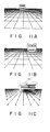
- Figs. 11A to 11C show detection states in which an intrusion object moves along a floor (background).
- Figs. 11A and 11B show images obtained when image pickup positions are rear and front positions, and
- Fig. 11C shows motion vectors obtained by connecting areas corresponding to the extracted optical flow.
- the motion vector string of the floor stationary relative to the environment is represented by straight lines radially generated from one point (FOE).
- the motion vector string of the moving object has a unique "start point" different from the FOE point, as indicated by reference numeral 111 surrounded by a broken line in Fig 11C. Generation of this point can be easily detected by using the intrusion decision circuit system 500.
- the video camera as the image surveillance apparatus having the above arrangement can be used in a variety of applications.
- the present invention is not limited to the particular embodiment described above.
- the image pickup element 20 is vibrated.
- the lens system 10 may be vibrated in place of the image pickup element as in the first embodiment to obtain the same effect as in the second embodiment.
- the present invention is applicable as a modification to a system including an image apparatus having a moving field of view as in a moving robot in addition to an arrangement in which the field of view is stationary and the image pickup plane vibrates, if the moving direction is regarded as a linear direction.
- a point for generating a motion vector string of the background area is not an FOE point generated by the vibration of the image pickup plane, but an FOE position obtained upon vibration of the image pickup plane in a third direction obtained by synthesizing the moving direction of the moving robot and the vibration of the image pickup plane. If the vibration speed is sufficiently higher than the speed of the moving robot, the FOE position almost coincides with the FOE point generated by only vibration of the image pickup plane.
- a highly reliable optical flow is obtained from time-serial images having small time and positional differences obtained upon vibration of a lens or image pickup element at a predetermined period in a direction of an optical axis, and image processing is performed to separate the movement of the background from that of the moving object by using the optical flow, thereby obtaining a high-quality image.
- image processing is performed to separate the movement of the background from that of the moving object by using the optical flow, thereby obtaining a high-quality image.
- intrusion detection can be performed while the field of view is always moving as in a moving robot, which detection cannot be performed by conventional direct differences. That is, by analyzing the motion vector string of the intrusion object to detect the moving direction, actions such as a collision preventive action and an emergency stop in operations of the robot can be appropriately selected, thus providing a variety of applications and advantageous effects.
Abstract
Description
- The present invention relates to a video camera and, more particularly, to a video camera having an improved "auto-focus scheme", capable of obtaining an in-focus image of an object moving at high speed, and having a image-processing function for the in-focus image.
- Conventional auto-focus schemes for a video camera are mainly classified into an "active scheme" and a "passive scheme" in accordance with whether a search signal serving as a distance measurement reference is output (emitted) or not.
- The active scheme emits, e.g., an ultrasonic wave or an infrared ray and receives the wave or ray reflected by an object. To the contrary, the passive scheme determines an object distance in accordance with only a video signal.
- In these two types of auto-focus schemes, automatic focusing is performed such that an in-focus decision signal is obtained from any means, and a focusing lens or the like is moved by a motor in accordance with a drive signal corresponding to this decision result.
- In such a conventional scheme, a focusing operation is performed after the in-focus state is decided, and the motor speed determines the focusing speed. Therefore, the focusing speed is limited, and an error often occurs in focusing on an object moving at a high speed.
- In an image picked up by fixing the focal position after an in-focus state is obtained, it can be kept in the in-focus position within a normal depth of field (i.e. focal depth of image), but is set in a defocus state in a range falling outside the normal depth of field. Therefore, an image focused in a larger depth of field cannot be obtained.
- In recent years, the importance of security in a variety of fields has been increasing along with the development of an information-oriented society. As an example, an image surveillance system used to detect an intruder or the like is available. When the number of surveillance areas checked by operators on monitors is increased, the operators who always check the monitors are overloaded, and reliability is degraded. Strong demand, therefore, has arisen for providing an automatic image surveillance system.
- When a moving robot is to be designed, a technique for detecting a moving object from instantaneously changing scenes obtained by a moving image pickup system is required. There are recently provided some systems for performing automatic surveillance using TV cameras. In these systems, a still image of an environment is picked up as a background image. Differences between this background image and time-serially obtained images are sequentially obtained, and a total sum of change amounts in a predetermined area is obtained. The total sum is compared with a threshold value to decide "intrusion" within the field of view.
- According to this scheme, in an environment where an illuminance varies as in an outdoor condition and a condition under fluorescent illumination, the brightness of the background area is changed due to variations in illumination. For this reason, it is difficult to separate and detect a change caused by an intrusion object, thereby degrading system reliability. According to this scheme, only the presence of an intrusion object is detected. Information representing the direction of movement of the intrusion object cannot be obtained. In addition, when the field of view is always changing as in a moving robot, the background area is also moved. Therefore, intrusion decision cannot be performed by only direct differences.
- In order to solve various problems described above, the optical flow in a target area is obtained from a time-serial image, and the background area is separated from the intrusion object on the basis of the optical flow, thereby performing highly reliable detection. Extensive studies have been made for a fundamental technique in this scheme as motion analysis in the fields of computer visions since late 1970.
- The techniques conventionally subjected to the above extensive studies are classified into a "gradient-based technique" using spatial and time changes in image densities and a "feature-based technique" for extracting features (characteristics) such as edges from an image and estimating a movement amount from a correlation result between the corresponding features in images having a time difference. The former technique has an advantage in that a movement amount with respect to an image as a whole can be obtained. However, since this technique uses a differential calculation, precision is greatly degraded by noise mixture in an image. In addition, estimated values for a coarse texture area and a boundary object area become inaccurate. The latter scheme has inaccurate movement amounts because feature values are used. However, degradation of precision by noise can be minimized in the latter technique.
- In either technique, since time differences and positional differences (the latter differences are typical in the case of moving robot applications) are large using a time-serial image directly obtained by a conventional TV camera, it is difficult to set ranges corresponding to differential calculations and feature values. A highly reliable optical flow cannot be obtained, and almost no practical applications have been made.
- As described above, in auto-focus schemes of the conventional image surveillance apparatuses and video cameras, an increase in focusing speed is limited by its structural characteristics, and at the same time an error occurs in an object moving at high speed. In addition, it is difficult to obtain a clear in-focus image in the range from the infinite position to the closest position (i.e., a wide range in the direction of the depth of field) in the entire image pickup area.
- When a time-serial image picked up by the conventional image pickup apparatus is used, time and positional differences are large, and a highly reliable optical flow is difficult to obtain.
- It is an object of the present invention to provide an image pickup apparatus such as a video camera capable of increasing a focusing speed and realizing a high-speed auto-focus operation free from operational errors.
- It is another object of the present invention to provide a video camera wherein a means for performing an image pickup operation of an image pickup element at an arbitrary position while a lens or the image pickup element is vibrated at a predetermined period in a direction of an optical axis is used, a time-serial image having small time and positional differences is obtained, and a highly reliable optical flow is obtained, thereby providing a highly precise image surveillance function by using the highly reliable optical flow.
- The gist of the present invention will be as follows.
- Instead of obtaining one image by a "focusing" operation, the image pickup element is always vibrated along the optical axis to perform image pickup operations at a plurality of arbitrary positions (i.e., intermediate positions within the amplitude of the vibration), and at least one image whose focal points are matched is obtained from the plurality of images obtained by the above image pickup operations, thereby extracting and visualizing its clear image.
- One of the characteristic features of the video camera according to the present invention lies in that the video camera comprises an image pickup element, having an auto-focus function, for picking up an optical image obtained through a lens system, means for vibrating the lens system or the image pickup element at a predetermined period in a direction of an optical axis, and for causing the image pickup element to perform image pickup operations at a plurality of arbitrary positions, and means for extracting a predetermined image signal from the plurality of image signals of different focal positions obtained by the image pickup element.
- The means for extracting the predetermined image signal employs the following techniques:
- (1) a technique for extracting an image signal having highest in-focus precision from the plurality of image signals of the different focal positions; and
- (2) a technique for dividing each of the plurality of image signals into a plurality of areas, performing focus detection in units of divided areas, and extracting divided areas (image signals) corresponding to highest in-focus precision from the areas and synthesizing the extracted areas.
- The vibration period of the image pickup element is preferably synchronized with a frame period of an image signal. In addition, a piezoelectric actuator is more preferable as a drive source for driving the image pickup element than a motor.
- The video camera according to the present invention is arranged as its application in the following manner.
- Another characteristic feature of this video camera lies in that the camera comprises means for picking up an optical image obtained through a lens system, means for vibrating a lens or an image pickup element at a predetermined period in a direction of an optical axis and for causing the image pickup element to perform image pickup operations at arbitrary positions, means for extracting an optical flow from a plurality of images obtained from the image pickup element, and means for detecting a moving object by using the optical flow, wherein time-serial images obtained by linearly vibrating the image pickup element or the lens in the direction of the optical axis are accumulated, an optical flow between the accumulated time-serial images is obtained, and motion vector strings obtained by connecting the corresponding vectors are separated into motion vector strings having FOE (Focus Of Expansion) points by the above vibration and motion vector strings without FOE points, thereby detecting an intrusion object.
- In the video camera according to the present invention, image pickup operations are performed while the image pickup element is always vibrated along the optical axis. Video signals obtained in the vibrated state of the image pickup element are processed in accordance with a predetermined sequence. Therefore, "high-speed focusing" operations can be performed, and at the same time, an image having a wider focal range from the infinite position to the closest position (i.e., a wide range in the direction of the depth of field of the object) can be obtained.
- A practical technique for obtaining the above image signal is as follows.
- An image signal is sampled at a plurality of arbitrary points during movement of the image pickup element, and only an image having highest in-focus precision is output and visualized. By using this highly precise image, predetermined image processing is performed while the vibration period of the image pickup element is synchronized with the frame period of the image signal, thereby always obtaining an in-focus motion image. In addition, the technique for processing the sampled images is changed to obtain an in-focus image in the wider range from the infinite position to the closest position.
- According to another technique, the vibration period of the image pickup element is synchronized with the frame period of the image signal so that the image reception positions are set identical to each other. Electronic auto-focus control is performed while the image reception positions or its setup are synchronized with the focus signals, thereby always obtaining an in-focus motion image.
- In another video camera according to the present invention, images are input while the lens or the image pickup element is vibrated to obtain time-serial images having small time and positional differences. As a result, "correlation search" can be easily performed. The highly precise optical flow can be obtained although this cannot be obtained by images picked up by the conventional image pickup element. In addition, vibration linearity can be precisely controlled, so that precision of FOE measurement can be improved. Therefore, the background can be separated from the motion of the moving object, thereby obtaining a highly precise image.
- This invention can be more fully understood from the following detailed description when taken in conjunction with the accompanying drawings, in which:
- Fig. 1 is a diagram showing a schematic arrangement including a section of the main part of a video camera along a direction of an optical axis according to the first embodiment of the present invention;
- Figs. 2A to 2C are views showing an arrangement of a video camera body and a piezoelectric actuator used in the first and second embodiments of the present invention;
- Fig. 3 is a graph showing a relationship between the position and time of an image pickup element of the video camera described above and the distance to an object;
- Figs. 4A and 4B are views showing states of image extraction in the first embodiment;
- Fig. 5 is a block diagram showing an overall arrangement of an image surveillance apparatus using the video camera of the second embodiment of the present invention;
- Fig. 6 is a diagram showing an arrangement of an image input circuit system;
- Fig. 7 is a diagram showing an arrangement of an FOE measuring circuit system;
- Fig. 8 is a diagram showing an arrangement of an optical flow detector system having a feature similarly (area) detector and a feature similarity memory;
- Fig. 9 is a diagram showing an arrangement of an intrusion decision circuit;
- Fig. 10 is a view showing a relationship between the "optical flow" of a stationary object and the FOE; and
- Figs. 11A to 11C are views showing a detection state while an intrusion object is moving along a floor (background), in which Figs. 11A and 11B show images obtained when image pickup positions are rear and front positions, and Fig. 11C shows motion vectors obtained by connecting areas corresponding to the extracted "optical flow".
- In the schematic arrangement of a video camera according to the present invention, as shown in Fig. 1, a
lens system 10 comprises a focusinglens 11 which is used in focusing but is not moved in zooming, azoom lens 12 moved to change the size of an image formed by the focusinglens 11, a focalposition correction lens 13 called a "compensator" moved to maintain an image formation position constant, and a relay lens orcondenser lens 14. Each of theselenses 11 to 14 comprises a plurality of lenses. Thelens system 10 comprise four groups of lenses. - A low-
pass filter 15 is located behind thelens system 10. Animage pickup element 20 is located behind the low-pass filter 15 to pick up an optical image. Optical information of an object to be photographed or the like is incident on theimage pickup element 20 through thelens system 10 and is picked up (photo-electrically) by theimage pickup element 20. - The
image pickup element 20 is always vibrated with a stroke (amplitude) of about 3 mm in a direction of an optical axis by avibration generation system 100 including apiezoelectric actuator 70. This stroke value is a value required to perform focusing upon movement of the image pickup element from the infinite position to the closest position of 1 m in an 1/2˝ optical system with zooming having a magnification of 6. A position x∞ of theimage pickup element 20 corresponding to a distance ∞ to the object is assumed to represent a position of the image pickup element closest to thelens system 10. A position xlm of theimage pickup element 20 corresponding to a distance of 1m to the object is assumed to represent a position of theimage pickup element 20 farthest from thelens system 10. During the operation, theimage pickup element 20 is vibrated between the above two points (stroke) to obtain a plurality of image signals. - A plurality of time-serial image signals obtained by the
image pickup element 20 are input to animage input system 200 for sequentially processing these plurality of image signals. Each input image signal is input to an imagesignal processing circuit 22 connected to theimage pickup element 20 and is subjected to processing such as A/D conversion. Thereafter, the precessed image signal is temporarily stored in an image field (i.e., frame) memory 35 (in units of time-serial signals). In-focus states of the plurality of converted image signals are detected by an in-focus decision circuit 24 connected to the imagesignal processing circuit 22 in units of images. The clearest image is selected from the plurality of image signals as a result of this detection. Desired images are partially extracted by, e.g., animage synthesizing circuit 26, as needed, and are synthesized as one image in anoutput image memory 60 by synthesis processing. The synthesized image is finally displayed and output on ascreen 80. - A
motor 50 in Fig. 1 constitutes an auto-zoom mechanism for driving thezoom lens 12 through a pinion and a worm gear in the direction of the optical axis to change a focal length. - A normal operating shape of the
piezoelectric actuator 70 is shown in Fig. 2A, and deformed shapes during its operations are shown in Figs. 2B and 2C. - A predetermined control signal having a magnitude falling with the range of qV is applied from an
actuator control circuit 73 to thepiezoelectric actuator 70 to always vibrate theimage pickup element 20 in the direction of the optical axis in Figs. 2A to 2C. The stroke (vibration) of thepiezoelectric actuator 70 is about 3 mm with respect to the object in the range from the infinite position to the closest position of 1 m in the 1/2˝ optical system with zooming having a magnification of 6. The image pickup element 37 obtains images of object positions corresponding to positions within this stroke. These image signals are supplied (input) to the imageinput circuit system 200. - The
lens system 10 comprises 4 lens groups consisting of the focusinglens 11, thezoom lens 12, the focalposition correction lens 13, and therelay lens 14. The low-pass filter 15 is located behind thelens system 10. An optical image is formed on the image pickup plane of theimage pickup element 20 such as a CCD through thelens system 10 and the low-pass filter 15. - The
piezoelectric actuator 70 is mounted on the side of theimage pickup element 20 opposite to its image pickup plane to move theimage pickup element 20 in the direction of the optical axis. Thepiezoelectric actuator 70 comprise S-shaped drivenbimorph elements 71a to 71f. These S-shaped driven bimorph elements are elements driven so that displacement directions of each bimorph element have opposite phases with respect to the center along the longitudinal direction. In the illustrated arrangement, two structures each consisting of three S-shaped driven bimorph elements (71a to 71c or 71d to 71f) connected in series with each other constitute cantilevered bimorph structures. When free ends of these two cantilevered bimorph are connected, the displacement is increased and the mechanical characteristics are improved. - Another pair of cantilevered bimorph structures are prepared as in the
bimorph elements 71a to 71f, as indicated by the alternate long and two short dashed lines, thereby further improving the mechanical characteristics. - A graph in Fig. 3 shows an operation of a "high-speed focusing" operation. Axial movement of the
image pickup element 20 is represented by a polygonal line. The position x of the image pickup element (range: infinite to 1 m) is plotted along the abscissa of this graph, and time t (required to obtain an infocus state) is plotted along the ordinate. A plurality of images corresponding to a plurality of arbitrary positions are sampled within the movement range of theimage pickup element 20. In this embodiment, theimage pickup element 20 performs sampling several times (5 times in this embodiment). Driving of theimage pickup element 20 by the movement actuator is set so that the image pickup element is stopped for a sampling (predetermined) time or more. Note that if the sampling (predetermined) time is sufficiently shorter than the movement time of theimage pickup element 20, the stop time need not be provided. - As shown in Fig. 4F, a plurality (five in this embodiment) of images are obtained during sampling between x∞ to xlm. High-frequency components of the image signals of these images are extracted and integrated to detect "focal point evaluation values" for detecting the degrees of focusing (i.e., focusing precision: in-focus precision). Comparison is performed in units of images. Of these images, one image having highest in-focus precision is selected and is output as an image. More specifically, the vibration period of the
image pickup element 20 is synchronized with the frame period of the image signal. For example, in the NTSC (National Television System Committee) scheme, when a moving speed between x∞ and xlm is set to be 1/60 sec., one reciprocal stroke (i.e., one period of the vibration) corresponds to one frame in the NTSC scheme. As a result, a motion image is always obtained in an in-focus state. - A video camera as an imaging apparatus suitable for an application in which an in-focus image is obtained on the entire screen if so desired further comprises the
image synthesizing circuit 26 for performing image synthesis processing. - More specifically, during each movement cycle between x∞ and xlm, the
image synthesizing circuit 26 divides each sampling image into a plurality of areas, as shown in Fig. 4B, and focus detection is performed in units of divided areas. During one movement cycle between x∞ and xlm, only in-focus areas are extracted from thememory 35 to synthesize them into one image. Therefore, an image (e.g., a motion image) having an extremely large depth of field, i.e., an in-focus image in the entire range from the infinite position to the closest position can be obtained. - In place of the above "extraction and synthesis technique", "filtering processing" for filtering a blur portion in each image or an "omission and synthesis technique" for omitting blur portions of the images and synthesizing the resultant images may be employed.
- Another arrangement of "high-speed focusing" operation will be described below. As in the previous embodiment, the
image pickup element 20 is vibrated in synchronism with the frame period of the image signal. The reception time of the image signal forming one frame is set sufficiently shorter than the vibration period, and only image signals at given focal positions within the vibration range are read. Since the vibration period coincides with the frame period, the read position can be electronically and arbitrarily controlled. A focal point evaluation value is detected from the read image signal, and the read position is fed back, thereby performing auto-focus processing. Since the auto-focus feedback system can be constituted by only electronic circuits, in-focus motion images can always be obtained. - The image signals obtained during movement between two points falling within the range of x∞ and xlm are received and displayed. For example, when a display operation is performed every 30 frames/sec as in the NTSC scheme, an image is obtained such that images overlap from an image of the closest position to an image of the infinite position. Although image quality is slightly degraded, this scheme can provide an in-focus image in a wide range from the infinite position to the closest position. Therefore, a clear object having a high contrast level can be sufficiently recognized. A better image can be obtained when image processing is performed.
- The above description exemplifies a technique for obtaining an in-focus image within a field. The
image pickup element 20 need not be operated at very high speed (e.g., vibration in this case), and any scheme may be employed if an appropriate in-focus image is obtained by simpler processing. - In the foregoing description of this embodiment, the
image pickup element 20 is vibrated. However, the same effect as the above embodiment can be obtained even if a lens system such as a focus control lens (correction lens 13) is similarly driven. The means for vibrating theimage pickup element 20 or thelens system 10 is not limited to thepiezoelectric actuator 70, but may be replaced with another means such as a voice coil motor. - Various changes and modifications may be made without departing from the spirit and scope of the present invention.
- The above embodiment according to the present invention can cope with an object or the like which is moving at high speed in a wider range of the depth of field, which operation has not been made by a conventional video camera with an auto-focus mechanism. There is therefore realized a video camera having a high focusing speed capable of obtaining an in-focus image at a higher speed in accordance with predetermined image processing.
- A
video camera body 1 shown in Fig. 5 is combined with the vibration generation system and is used in an image surveillance apparatus such as an intrusion surveillance camera according to the second embodiment of the present invention. For example, image surveillance apparatuses are applied to intrusion detection in department stores and offices and obstacle detection in moving robots. - This embodiment aims at providing an image surveillance video camera which utilizes the gist of the present invention that "a lens or image pickup element of a camera or the like is vibrated at a predetermined period in a direction of an optical axis to input instantaneous images, thereby acquiring time-serial images having small time and positional differences". More specifically, by obtaining a highly reliable "optical flow" coping with an object moving at high speed which cannot be captured by zooming in an image of a conventional image pickup apparatus such as a video camera, the background can be separated from motion of the moving object in an image, thereby providing an image surveillance apparatus for easily obtaining a high-quality (i.e., in-focus) image.
- Referring to Fig. 5, the
video camera body 1 is a combination of animage pickup element 20 and avibration generation system 100 for moving the element itself or part or all of alens system 10 with a predetermined amplitude at a predetermined period in the direction of the optical axis. Thisvibration generation system 100 comprises apiezoelectric actuator 70, anactuator control circuit 73, and a drive circuit (not shown). An image output corresponding to a half cycle of the vibration period is sequentially transferred to animage input system 200 connected to theimage pickup element 20. Theimage input system 200 performs predetermined image processing (details will be described with reference to Fig. 6) such as digital conversion of the image output. The processed image output is stored in an image memory 35 (in units of time-serial signals) through animage information bus 8. - On the other hand, an optical
flow detector system 300, an FOEmeasuring circuit system 400, anintrusion decision circuit 500, and anoptical flow memory 65, all of which are associated with surveillance processing (to be described in detail later) are connected in parallel with acontrol bus 9 connected to aCPU 90 for controlling the overall operation of the apparatus. - The optical
flow detector system 300 connected to thecontrol bus 9 and theimage bus 8 obtains "motion" associated with a corresponding area from a plurality of time-serial images prestored in theimage memory 35 in accordance with predetermined analysis processing and detects an "optical flow" of this area. An FOE detector 4 analyzes the "motions" of the background and the object to measure an FOE (Focus Of Expansion) point where the optical flow of the stationary object obtained upon movement of an image pickup plane along the direction of the optical axis is generated. Theintrusion decision circuit 500 decides whether the optical flow contains components which are not generated from the FOE point, thereby detecting "intrusion" of, e.g., an object moving into the field of view of the intrusion surveillance camera. - Arrangements of the respective blocks in Fig. 5 will be described below.
- Fig. 6 shows the
image input system 200 and the associated image memory (field memories) 35 connected thereto through theimage bus 8. - The arrangement of the
image input system 200 will be as follows. - An image signal output from the
camera body 1 is converted into a digital signal by an A/D converter 6. The digital signal is stored in theimage memory 35 through anITV interface 7 and theimage bus 8. The image memory (e.g., field memories) 35 is also connected to thecontrol bus 9, so that random read/write access can be performed. By using theimage input system 200, a plurality of images (i.e., time-serial images) of a half cycle (i.e., a forward stroke of the image pickup plane position toward the lenses) of the vibration period are sequentially stored in thefield memories 35. - Fig. 7 shows an arrangement of the FOE
measuring circuit system 400. - As illustrated in Fig. 10, the optical flow of the stationary object obtained upon movement of the image pickup plane in the direction of the optical image is a flow generated from one point. This point is called the FOE. By using this finding, the optical flow of the stationary environment is obtained in advance, and a
line detecting circuit 42 obtains linear expressions from "motion vector strings" obtained by connecting the corresponding areas. These linear expressions can be derived using the method of least squares method. AnFOE calculation circuit 44 obtains intersections of the respective lines to calculate FOE coordinates. For example, if three or more straight lines (e.g., segments) are obtained, the center of gravity of these intersections is set as the FOE point (position). The FOE coordinates are stored in anFOE memory 46. - Fig. 8 shows an arrangement of the optical
flow detector system 300. - The following processing will be performed to analyze image features, similarity points between a plurality of images, and the like.
- Images of two consecutive moments are sequentially selected from the time-serial images stored in the
field memories 35. A characteristicarea selection circuit 32 selects a target area for calculating motion vectors from the image of the previous moment (i.e., the image located behind the image pickup plane). Parameters such as an area size and a maximum area count are prestored in acharacteristic memory 36. Character (feature) area decision processing is realized by calculating a "variance value" inside the area and selecting an area having a value larger than a predetermined threshold value supplied to thecharacteristic memory 36. Asimilarity calculating circuit 34 searches the image of the next moment (i.e., the image located in front of the image pickup plane) and selects an area having most similar "density characteristics" in the respective characteristic areas. The range of search is preset in asimilarity memory 38. In practice, however, the range of search may be limited to a very narrow range because differences in image positions are very small values. As a result, reliability can be improved and the processing time can be shortened. A difference vector between the central positions of these two areas is sequentially stored as a motion vector in anoptical flow memory 65. - A similarity representing a degree of similarity between two images is calculated by equation (1) as follows:

- I(t-1)ij:
- brightness of a pixel at a position (i,j) of an image at the previous moment
- I(t)ij:
- brightness of a pixel at the position (i,j) of an image at the next moment
- Σ:
- total sum within the characteristic area
- Fig. 9 shows an arrangement of the
intrusion decision circuit 500. A linear expression is applied by theline detecting circuit 42 from a motion vector string obtained by connecting the corresponding areas. Adecision circuit 52 decides whether this line passes through the FOE point stored in theFOE memory 46, thereby calculating the number of lines (segments) not passing through the FOE point. This decision processing is performed by comparing a predetermined threshold value preset in aparameter memory 56 with the number of lines not passing through the FOE point. - As illustrated in Fig. 10, the optical flow of the stationary object obtained upon movement of the image pickup plane in the direction of the optical image forms a "flow" in which line segments indicated by arrows and generated from the FOE point are linearly continuous.
- Figs. 11A to 11C show detection states in which an intrusion object moves along a floor (background). Figs. 11A and 11B show images obtained when image pickup positions are rear and front positions, and Fig. 11C shows motion vectors obtained by connecting areas corresponding to the extracted optical flow.
- The motion vector string of the floor stationary relative to the environment is represented by straight lines radially generated from one point (FOE). To the contrary, the motion vector string of the moving object has a unique "start point" different from the FOE point, as indicated by reference numeral 111 surrounded by a broken line in Fig 11C. Generation of this point can be easily detected by using the intrusion
decision circuit system 500. - The video camera as the image surveillance apparatus having the above arrangement can be used in a variety of applications.
- The present invention is not limited to the particular embodiment described above. In the above embodiment, the
image pickup element 20 is vibrated. Thelens system 10 may be vibrated in place of the image pickup element as in the first embodiment to obtain the same effect as in the second embodiment. - The present invention is applicable as a modification to a system including an image apparatus having a moving field of view as in a moving robot in addition to an arrangement in which the field of view is stationary and the image pickup plane vibrates, if the moving direction is regarded as a linear direction. In this modification, a point for generating a motion vector string of the background area is not an FOE point generated by the vibration of the image pickup plane, but an FOE position obtained upon vibration of the image pickup plane in a third direction obtained by synthesizing the moving direction of the moving robot and the vibration of the image pickup plane. If the vibration speed is sufficiently higher than the speed of the moving robot, the FOE position almost coincides with the FOE point generated by only vibration of the image pickup plane.
- In addition, when the motion vector string of the intrusion object is analyzed, its moving direction can be detected.
- Various changes and modifications may be made without departing from the spirit and scope of the invention.
- A highly reliable optical flow is obtained from time-serial images having small time and positional differences obtained upon vibration of a lens or image pickup element at a predetermined period in a direction of an optical axis, and image processing is performed to separate the movement of the background from that of the moving object by using the optical flow, thereby obtaining a high-quality image. By changing a sampling image processing technique in image processing in accordance with an application purpose, in-focus motion images throughout the entire range from the infinite position to the closest position can be picked up. For example, the present invention can be applied to a variety of applications such as an image surveillance apparatus (e.g., an intrusion surveillance camera) which always requires in-focus images.
- In addition, intrusion detection can be performed while the field of view is always moving as in a moving robot, which detection cannot be performed by conventional direct differences. That is, by analyzing the motion vector string of the intrusion object to detect the moving direction, actions such as a collision preventive action and an emergency stop in operations of the robot can be appropriately selected, thus providing a variety of applications and advantageous effects.
Claims (13)
- A video camera characterized by comprising:
a video camera body (1) having an image pickup element (20) for picking up optical information incident on a lens system (10); and
vibration generating means (100), coupled to said image pickup element, for applying a vibration to said image pickup element or said lens system with a predetermined stroke (amplitude) in a direction of an optical axis and causing said image pickup element to perform image pickup operations at a plurality of arbitrary positions. - A video camera according to claim 1, characterized in that said vibration generating means (100) comprises:
a vibration drive source (70), coupled to said lens system (10) or said image pickup element (20), for applying a vibration drive force to at least one of said lens system and said image pickup element; and
vibration source control means (73) for applying a predetermined control signal to said vibration drive source to generate a vibration at a predetermined period. - A video camera according to claim 2, characterized in that
said vibration source control means (73) comprises an actuator control circuit; and
said vibration drive source (70) comprises a piezoelectric actuator,
said piezoelectric actuator being constituted by two cantilevered bimorph structures each consisting of a plurality of S-shaped driven bimorph elements (71a - 71f). - A video camera characterized by comprising:
an image pickup element (20) for picking up an optical image obtained through a lens system (10);
means (100) for vibrating said lens system or said image pickup element at a predetermined period in a direction of an optical axis and causing said image pickup element to perform image pickup operations at a plurality of arbitrary positions; and
sampling means (22) for extracting a predetermined image signal from a plurality of image signals of different focal positions obtained by said image pickup element. - A video camera characterized by comprising:
an image pickup element (20) for receiving optical information of an object to be photographed after the optical information passes through said lens system, and performing an image pickup operation;
vibration generating means (100), coupled to said image pickup element, for applying a vibration to said image pickup element with a predetermined stroke (amplitude) in the direction of the optical axis;
sampling means (22) for extracting image signals at predetermined time intervals from a plurality of image signals of different focal positions obtained from said image pickup element at a plurality of arbitrary positions within the stroke; and
image memory means (35) for time-serially storing sampling images acquired from said image pickup element. - A video camera according to claim 5, characterized by further comprising:
in-focus decision extracting means (24) for extracting a high-frequency component from an image signal of the sampling image, detecting a focal point evaluation value for evaluating a degree of focusing upon integrating processing, comparing the focal point evaluation values of the plurality of images, and selecting a sampling image having a largest focusing precision value. - A video camera according to claim 5, characterized by further comprising:
image synthesizing means (26) for dividing the sampling image into a plurality of areas as needed, performing focus detection in each divided area, and extracting only in-focus areas from said image memory means to synthesize the in-focus areas into a single image. - A video camera characterized by comprising:
vibration generating means (100) for vibrating a lens system (10) or an image pickup element (20) at a predetermined period in a direction of an optical axis;
image pickup control means (200) for causing said image pickup element to perform image pickup operations at arbitrary positions within a vibration stroke, further comprising
image processing means (300, 400, 500) for extracting an optical flow from a plurality of images obtained by the image pickup operations and detecting a moving object using the optical flow. - A video camera according to claim 5, characterized by including:
said lens system (10) for focusing optical information of an object to be photographed or the like;
said image pickup element (20) for performing electrical image pickup operations;
said vibration generating means (100) for vibrating said image pickup element itself, or part or all of said lens system with a predetermined amplitude at a predetermined period in a direction of an optical axis;
an image input system (200), connected to said vibration generating means, for performing predetermined information conversion processing for processing an image output; and
said image memory (35) for storing the image output;
further including a CPU (90) for controlling the image processing, a control bus (9) connected to said CPU to transmit a control signal from said CPU, and an image bus (8) for transmitting image information,
wherein said control bus is connected to:
an optical flow detecting system (300) for detecting features and similarity points of the image;
an optical flow memory (65) for storing information associated with the optical flow for surveillance processing;
an FOE (Focus of Expansion) measuring circuit system (400) for measuring an FOE point from which the optical flow of a stationary object in the image is generated; and
an intrusion decision circuit system (500) for detecting an intrusion object. - A video camera according to claim 9, characterized in that
said image input system (200) performs predetermined conversion processing of input image information obtained in a half cycle of a vibration period and stores processed information in said image memory through said image bus, and
said image input system (200) comprises:
an A/D converter (6) for converting the image signal output from said camera body (1) into a digital signal; and
an ITV interface (7) for transmitting the digital image signal to said image memory (35). - A video camera according to claim 9, characterized in that
said optical flow detecting system (300) obtains a motion associated with a corresponding area from a plurality of time-serial images prestored in said image memory in accordance with predetermined analysis processing to obtain an optical flow of the corresponding area, and
said optical flow detecting system (300) comprises:
a feature/similarity detector circuit (310) for detecting features and similarity points of the images; and
a feature/similarly detection memory (350) for storing the detection process and a detection result thereof. - A video camera according to claim 9, characterized in that
said FOE measuring circuit system (400) analyzes motions of a background and an object to obtain an optical flow between images of the background and the object, and measures an FOE (Focus Of Expansion) point in which an optical flow of a stationary object obtained upon movement of an image pickup plane in a direction of an optical axis is generated from a motion vector string obtained by connecting corresponding vectors of the optical flow, and
said FOE measuring circuit system (400) comprises:
a line detecting circuit (42) for obtaining linear expressions from the motion vector string based on the optical flow by using a predetermined method;
an FOE calculation circuit (44) for obtaining intersections of a plurality of straight lines represented by the linear expressions and calculating coordinates of the FOE point according to a predetermined method; and
an FOE memory (46) for storing the calculated coordinates of the FOE point. - A video camera according to claim 9, characterized in that
said intrusion decision circuit system (500) decides to separate the plurality of images into an image having the FOE point and an image having no FOE point to detect an intrusion object, and
said intrusion decision circuit system (500) comprises:
a decision circuit (52) for determining that the lines obtained by said FOE measuring circuit system (400) pass through the FOE point; and
a parameter memory (56) for storing a predetermined threshold value and the decision result.
Applications Claiming Priority (4)
| Application Number | Priority Date | Filing Date | Title |
|---|---|---|---|
| JP292574/90 | 1990-10-29 | ||
| JP02292574A JP3099893B2 (en) | 1990-10-29 | 1990-10-29 | Video camera |
| JP249476/91 | 1991-09-27 | ||
| JP3249476A JPH0591513A (en) | 1991-09-27 | 1991-09-27 | Image monitoring device |
Publications (3)
| Publication Number | Publication Date |
|---|---|
| EP0484076A2 true EP0484076A2 (en) | 1992-05-06 |
| EP0484076A3 EP0484076A3 (en) | 1993-06-30 |
| EP0484076B1 EP0484076B1 (en) | 1996-12-18 |
Family
ID=26539314
Family Applications (1)
| Application Number | Title | Priority Date | Filing Date |
|---|---|---|---|
| EP91309926A Expired - Lifetime EP0484076B1 (en) | 1990-10-29 | 1991-10-28 | Video camera having focusing and image-processing function |
Country Status (4)
| Country | Link |
|---|---|
| US (1) | US5307170A (en) |
| EP (1) | EP0484076B1 (en) |
| KR (1) | KR960005204B1 (en) |
| CA (1) | CA2054344C (en) |
Cited By (5)
| Publication number | Priority date | Publication date | Assignee | Title |
|---|---|---|---|---|
| WO2003067323A1 (en) * | 2002-01-15 | 2003-08-14 | Afsenius Sven-Aake | Digital camera with viewfinder designed for improved depth of field photographing |
| WO2007107017A1 (en) * | 2006-03-22 | 2007-09-27 | Sinar Ag | Image taking apparatus and control unit for focus control |
| EP2151990A1 (en) * | 2008-08-08 | 2010-02-10 | Honeywell International Inc. | Autofocus image acquisition system |
| CN105208259A (en) * | 2014-06-17 | 2015-12-30 | 中兴通讯股份有限公司 | Method for optimizing camera autofocus and camera |
| CN105323477A (en) * | 2013-08-01 | 2016-02-10 | 华为终端有限公司 | Photographing method and device |
Families Citing this family (99)
| Publication number | Priority date | Publication date | Assignee | Title |
|---|---|---|---|---|
| JP3513950B2 (en) * | 1993-12-14 | 2004-03-31 | 株式会社ニコン | Image stabilization camera |
| US5559695A (en) * | 1994-12-27 | 1996-09-24 | Hughes Aircraft Company | Apparatus and method for self-calibrating visual time-to-contact sensor |
| JP3471156B2 (en) * | 1995-05-30 | 2003-11-25 | シャープ株式会社 | Image shift mechanism and imaging device |
| JPH099138A (en) * | 1995-06-23 | 1997-01-10 | Canon Inc | High quality image input device provided with vibration countermeasure function |
| US6587148B1 (en) * | 1995-09-01 | 2003-07-01 | Canon Kabushiki Kaisha | Reduced aliasing distortion optical filter, and an image sensing device using same |
| EP1012725A4 (en) * | 1996-05-22 | 2004-11-10 | Geovector Corp | Mehtod and apparatus for controlling electrical devices in response to sensed conditions |
| US6804726B1 (en) | 1996-05-22 | 2004-10-12 | Geovector Corporation | Method and apparatus for controlling electrical devices in response to sensed conditions |
| JPH1091795A (en) * | 1996-09-12 | 1998-04-10 | Toshiba Corp | Device for detecting mobile object and method therefor |
| JP3612397B2 (en) * | 1996-12-13 | 2005-01-19 | セイコープレシジョン株式会社 | Camera shutter |
| JP3052893B2 (en) * | 1997-05-16 | 2000-06-19 | 日本電気株式会社 | Video encoding device |
| JP3803950B2 (en) * | 1999-03-04 | 2006-08-02 | 株式会社リコー | Image composition processing method, image composition processing apparatus, and recording medium |
| US7003134B1 (en) * | 1999-03-08 | 2006-02-21 | Vulcan Patents Llc | Three dimensional object pose estimation which employs dense depth information |
| US6693672B1 (en) * | 1999-05-20 | 2004-02-17 | Hewlett-Packard Development Company, L.P. | Method and apparatus for detecting set of images and selecting most focused image |
| JP4246326B2 (en) * | 1999-08-27 | 2009-04-02 | 東レエンジニアリング株式会社 | Surface shape measuring method and apparatus |
| TW397930B (en) * | 1999-11-30 | 2000-07-11 | Dynacolor Inc | The multi-focus picturing method and its device |
| JP4280957B2 (en) * | 2000-08-17 | 2009-06-17 | ソニー株式会社 | Image processing apparatus and method, and recording medium |
| US7200246B2 (en) | 2000-11-17 | 2007-04-03 | Honeywell International Inc. | Object detection |
| US6711279B1 (en) | 2000-11-17 | 2004-03-23 | Honeywell International Inc. | Object detection |
| US6841780B2 (en) | 2001-01-19 | 2005-01-11 | Honeywell International Inc. | Method and apparatus for detecting objects |
| JP3530906B2 (en) * | 2001-03-30 | 2004-05-24 | ミノルタ株式会社 | Imaging position detection program and camera |
| JP2002323649A (en) * | 2001-04-26 | 2002-11-08 | Hitachi Ltd | Imaging unit |
| US7953219B2 (en) * | 2001-07-19 | 2011-05-31 | Nice Systems, Ltd. | Method apparatus and system for capturing and analyzing interaction based content |
| WO2003021927A2 (en) * | 2001-09-06 | 2003-03-13 | Nice Systems Ltd. | Recording of interactions between a customer and a sales person at a point of sales |
| US7728870B2 (en) | 2001-09-06 | 2010-06-01 | Nice Systems Ltd | Advanced quality management and recording solutions for walk-in environments |
| US7573421B2 (en) * | 2001-09-24 | 2009-08-11 | Nice Systems, Ltd. | System and method for the automatic control of video frame rate |
| EP1472869A4 (en) * | 2002-02-06 | 2008-07-30 | Nice Systems Ltd | System and method for video content analysis-based detection, surveillance and alarm management |
| US20050128304A1 (en) * | 2002-02-06 | 2005-06-16 | Manasseh Frederick M. | System and method for traveler interactions management |
| AU2003207979A1 (en) * | 2002-02-06 | 2003-09-02 | Nice Systems Ltd. | Method and apparatus for video frame sequence-based object tracking |
| US7436887B2 (en) * | 2002-02-06 | 2008-10-14 | Playtex Products, Inc. | Method and apparatus for video frame sequence-based object tracking |
| JP4477811B2 (en) * | 2002-02-27 | 2010-06-09 | Hoya株式会社 | Mounting plate for solid-state image sensor and mounting method to the mounting plate |
| US7761544B2 (en) | 2002-03-07 | 2010-07-20 | Nice Systems, Ltd. | Method and apparatus for internal and external monitoring of a transportation vehicle |
| US20060089837A1 (en) * | 2003-04-09 | 2006-04-27 | Roy Adar | Apparatus, system and method for dispute resolution, regulation compliance and quality management in financial institutions |
| WO2005018097A2 (en) * | 2003-08-18 | 2005-02-24 | Nice Systems Ltd. | Apparatus and method for audio content analysis, marking and summing |
| US8050463B2 (en) | 2005-01-26 | 2011-11-01 | Honeywell International Inc. | Iris recognition system having image quality metrics |
| US8064647B2 (en) | 2006-03-03 | 2011-11-22 | Honeywell International Inc. | System for iris detection tracking and recognition at a distance |
| US8705808B2 (en) | 2003-09-05 | 2014-04-22 | Honeywell International Inc. | Combined face and iris recognition system |
| US8098901B2 (en) | 2005-01-26 | 2012-01-17 | Honeywell International Inc. | Standoff iris recognition system |
| US8442276B2 (en) | 2006-03-03 | 2013-05-14 | Honeywell International Inc. | Invariant radial iris segmentation |
| US8090157B2 (en) | 2005-01-26 | 2012-01-03 | Honeywell International Inc. | Approaches and apparatus for eye detection in a digital image |
| US7593550B2 (en) | 2005-01-26 | 2009-09-22 | Honeywell International Inc. | Distance iris recognition |
| AU2003276661A1 (en) * | 2003-11-05 | 2005-05-26 | Nice Systems Ltd. | Apparatus and method for event-driven content analysis |
| US7751694B2 (en) * | 2004-02-13 | 2010-07-06 | Angstrom, Inc. | Three-dimensional endoscope imaging and display system |
| WO2005086046A1 (en) * | 2004-03-10 | 2005-09-15 | Nice Systems Ltd. | Apparatus and method for generating a content-based follow up |
| US7086139B2 (en) * | 2004-04-30 | 2006-08-08 | Hitachi Global Storage Technologies Netherlands B.V. | Methods of making magnetic write heads using electron beam lithography |
| US8204884B2 (en) * | 2004-07-14 | 2012-06-19 | Nice Systems Ltd. | Method, apparatus and system for capturing and analyzing interaction based content |
| WO2006021943A1 (en) * | 2004-08-09 | 2006-03-02 | Nice Systems Ltd. | Apparatus and method for multimedia content based |
| US8724891B2 (en) * | 2004-08-31 | 2014-05-13 | Ramot At Tel-Aviv University Ltd. | Apparatus and methods for the detection of abnormal motion in a video stream |
| US8078463B2 (en) * | 2004-11-23 | 2011-12-13 | Nice Systems, Ltd. | Method and apparatus for speaker spotting |
| WO2006082591A2 (en) * | 2005-02-07 | 2006-08-10 | Nice Systems Ltd. | Upgrading performance using aggregated information shared between management systems |
| US20060197865A1 (en) * | 2005-03-07 | 2006-09-07 | Henryk Birecki | Focus device for cameras |
| US8005675B2 (en) * | 2005-03-17 | 2011-08-23 | Nice Systems, Ltd. | Apparatus and method for audio analysis |
| US10019877B2 (en) * | 2005-04-03 | 2018-07-10 | Qognify Ltd. | Apparatus and methods for the semi-automatic tracking and examining of an object or an event in a monitored site |
| US7386105B2 (en) * | 2005-05-27 | 2008-06-10 | Nice Systems Ltd | Method and apparatus for fraud detection |
| JP4794963B2 (en) * | 2005-06-28 | 2011-10-19 | キヤノン株式会社 | Imaging apparatus and imaging program |
| US20080040110A1 (en) * | 2005-08-08 | 2008-02-14 | Nice Systems Ltd. | Apparatus and Methods for the Detection of Emotions in Audio Interactions |
| WO2007086042A2 (en) * | 2006-01-25 | 2007-08-02 | Nice Systems Ltd. | Method and apparatus for segmentation of audio interactions |
| JP4579169B2 (en) * | 2006-02-27 | 2010-11-10 | 富士フイルム株式会社 | Imaging condition setting method and imaging apparatus using the same |
| WO2007101275A1 (en) | 2006-03-03 | 2007-09-07 | Honeywell International, Inc. | Camera with auto-focus capability |
| JP2009529197A (en) | 2006-03-03 | 2009-08-13 | ハネウェル・インターナショナル・インコーポレーテッド | Module biometrics collection system architecture |
| GB2450023B (en) | 2006-03-03 | 2011-06-08 | Honeywell Int Inc | An iris image encoding method |
| GB2448653B (en) | 2006-03-03 | 2011-03-23 | Honeywell Int Inc | Single lens splitter camera |
| US8725518B2 (en) * | 2006-04-25 | 2014-05-13 | Nice Systems Ltd. | Automatic speech analysis |
| WO2007135656A1 (en) * | 2006-05-18 | 2007-11-29 | Nice Systems Ltd. | Method and apparatus for combining traffic analysis and monitoring center in lawful interception |
| US7711259B2 (en) * | 2006-07-14 | 2010-05-04 | Aptina Imaging Corporation | Method and apparatus for increasing depth of field for an imager |
| JP4367475B2 (en) * | 2006-10-06 | 2009-11-18 | アイシン精機株式会社 | Moving object recognition apparatus, moving object recognition method, and computer program |
| US7822605B2 (en) * | 2006-10-19 | 2010-10-26 | Nice Systems Ltd. | Method and apparatus for large population speaker identification in telephone interactions |
| KR100772586B1 (en) * | 2006-10-20 | 2007-11-02 | 삼성전기주식회사 | Camera module |
| US7631046B2 (en) * | 2006-10-26 | 2009-12-08 | Nice Systems, Ltd. | Method and apparatus for lawful interception of web based messaging communication |
| US7577246B2 (en) * | 2006-12-20 | 2009-08-18 | Nice Systems Ltd. | Method and system for automatic quality evaluation |
| JP4759524B2 (en) * | 2007-01-09 | 2011-08-31 | 富士フイルム株式会社 | Electronic camera shake correction method and apparatus, electronic camera shake correction program, and imaging apparatus |
| US20080189171A1 (en) * | 2007-02-01 | 2008-08-07 | Nice Systems Ltd. | Method and apparatus for call categorization |
| US8571853B2 (en) * | 2007-02-11 | 2013-10-29 | Nice Systems Ltd. | Method and system for laughter detection |
| US7599475B2 (en) * | 2007-03-12 | 2009-10-06 | Nice Systems, Ltd. | Method and apparatus for generic analytics |
| US8063889B2 (en) | 2007-04-25 | 2011-11-22 | Honeywell International Inc. | Biometric data collection system |
| US20090012826A1 (en) * | 2007-07-02 | 2009-01-08 | Nice Systems Ltd. | Method and apparatus for adaptive interaction analytics |
| JP5381060B2 (en) * | 2008-02-05 | 2014-01-08 | 株式会社リコー | Imaging apparatus and image processing method thereof |
| US8436907B2 (en) | 2008-05-09 | 2013-05-07 | Honeywell International Inc. | Heterogeneous video capturing system |
| KR100890590B1 (en) * | 2008-10-02 | 2009-03-25 | 주식회사 세코닉스 | Camera module and driving method thereof |
| KR101499540B1 (en) * | 2008-10-24 | 2015-03-06 | 삼성전자주식회사 | Image pick-up device and image processing method using the same |
| US8280119B2 (en) | 2008-12-05 | 2012-10-02 | Honeywell International Inc. | Iris recognition system using quality metrics |
| US8630464B2 (en) | 2009-06-15 | 2014-01-14 | Honeywell International Inc. | Adaptive iris matching using database indexing |
| US8472681B2 (en) | 2009-06-15 | 2013-06-25 | Honeywell International Inc. | Iris and ocular recognition system using trace transforms |
| US8305486B2 (en) * | 2009-12-30 | 2012-11-06 | Carestream Health, Inc. | Auto-focus intra-oral camera having a linear piezoelectric actuator |
| US8742887B2 (en) | 2010-09-03 | 2014-06-03 | Honeywell International Inc. | Biometric visitor check system |
| US9292973B2 (en) | 2010-11-08 | 2016-03-22 | Microsoft Technology Licensing, Llc | Automatic variable virtual focus for augmented reality displays |
| US9304319B2 (en) | 2010-11-18 | 2016-04-05 | Microsoft Technology Licensing, Llc | Automatic focus improvement for augmented reality displays |
| US9213405B2 (en) | 2010-12-16 | 2015-12-15 | Microsoft Technology Licensing, Llc | Comprehension and intent-based content for augmented reality displays |
| US9153195B2 (en) | 2011-08-17 | 2015-10-06 | Microsoft Technology Licensing, Llc | Providing contextual personal information by a mixed reality device |
| WO2013028908A1 (en) | 2011-08-24 | 2013-02-28 | Microsoft Corporation | Touch and social cues as inputs into a computer |
| US9323325B2 (en) | 2011-08-30 | 2016-04-26 | Microsoft Technology Licensing, Llc | Enhancing an object of interest in a see-through, mixed reality display device |
| US9262840B2 (en) * | 2012-06-08 | 2016-02-16 | Correlated Solutions, Inc. | Optical non-contacting apparatus for shape and deformation measurement of vibrating objects using image analysis methodology |
| US9716847B1 (en) | 2012-09-25 | 2017-07-25 | Google Inc. | Image capture device with angled image sensor |
| US8983176B2 (en) | 2013-01-02 | 2015-03-17 | International Business Machines Corporation | Image selection and masking using imported depth information |
| JP6214232B2 (en) * | 2013-06-20 | 2017-10-18 | キヤノン株式会社 | Vibration actuator, replacement lens, imaging device, and automatic stage |
| US9196027B2 (en) | 2014-03-31 | 2015-11-24 | International Business Machines Corporation | Automatic focus stacking of captured images |
| US9449234B2 (en) | 2014-03-31 | 2016-09-20 | International Business Machines Corporation | Displaying relative motion of objects in an image |
| US9300857B2 (en) | 2014-04-09 | 2016-03-29 | International Business Machines Corporation | Real-time sharpening of raw digital images |
| US11006819B2 (en) | 2014-10-16 | 2021-05-18 | Karl Storz Endovision, Inc. | Focusable camera module for endoscopes |
| US20190258313A1 (en) * | 2016-11-07 | 2019-08-22 | Changchun Ruixinboguan Technology Development Co., Ltd. | Systems and methods for interaction with an application |
Citations (7)
| Publication number | Priority date | Publication date | Assignee | Title |
|---|---|---|---|---|
| US4404594A (en) * | 1981-11-02 | 1983-09-13 | Itek Corporation | Imaging system with enlarged depth of field |
| JPS61116313A (en) * | 1984-11-12 | 1986-06-03 | Matsushita Electric Ind Co Ltd | Automatic focus detector |
| JPS6211836A (en) * | 1985-07-10 | 1987-01-20 | Canon Inc | Correcting device for depth of focus |
| JPS6356622A (en) * | 1986-08-27 | 1988-03-11 | Fuji Photo Film Co Ltd | Automatic focus adjusting device for electronic camera |
| JPS6373213A (en) * | 1986-09-17 | 1988-04-02 | Victor Co Of Japan Ltd | Auto-focusing device |
| DE3905619A1 (en) * | 1988-02-23 | 1989-08-31 | Olympus Optical Co | IMAGE INPUT / OUTPUT DEVICE |
| JPH1175456A (en) * | 1997-09-12 | 1999-03-23 | Seirei Ind Co Ltd | Stem-treating mechanism of travel type machine for treating stem |
Family Cites Families (7)
| Publication number | Priority date | Publication date | Assignee | Title |
|---|---|---|---|---|
| JPS61136387A (en) * | 1984-12-07 | 1986-06-24 | Toshiba Corp | Drive pulse generating circuit of solid-state image pickup device |
| US4780739A (en) * | 1985-09-06 | 1988-10-25 | Canon Kabushiki Kaisha | Anti-vibration imaging device |
| JPH01175456A (en) * | 1987-12-29 | 1989-07-11 | Fujitsu Ltd | Image input device |
| US5086338A (en) * | 1988-11-21 | 1992-02-04 | Canon Kabushiki Kaisha | Color television camera optical system adjusting for chromatic aberration |
| JPH0817452B2 (en) * | 1989-01-30 | 1996-02-21 | 松下電器産業株式会社 | Automatic focus adjustment device |
| JPH0313073A (en) * | 1989-06-09 | 1991-01-22 | Canon Inc | Automatic focus adjusting device |
| JPH03143173A (en) * | 1989-10-30 | 1991-06-18 | Toshiba Corp | Automatic focusing device for video camera |
-
1991
- 1991-10-28 EP EP91309926A patent/EP0484076B1/en not_active Expired - Lifetime
- 1991-10-28 CA CA002054344A patent/CA2054344C/en not_active Expired - Fee Related
- 1991-10-29 US US07/784,586 patent/US5307170A/en not_active Expired - Fee Related
- 1991-10-29 KR KR1019910019267A patent/KR960005204B1/en not_active IP Right Cessation
Patent Citations (7)
| Publication number | Priority date | Publication date | Assignee | Title |
|---|---|---|---|---|
| US4404594A (en) * | 1981-11-02 | 1983-09-13 | Itek Corporation | Imaging system with enlarged depth of field |
| JPS61116313A (en) * | 1984-11-12 | 1986-06-03 | Matsushita Electric Ind Co Ltd | Automatic focus detector |
| JPS6211836A (en) * | 1985-07-10 | 1987-01-20 | Canon Inc | Correcting device for depth of focus |
| JPS6356622A (en) * | 1986-08-27 | 1988-03-11 | Fuji Photo Film Co Ltd | Automatic focus adjusting device for electronic camera |
| JPS6373213A (en) * | 1986-09-17 | 1988-04-02 | Victor Co Of Japan Ltd | Auto-focusing device |
| DE3905619A1 (en) * | 1988-02-23 | 1989-08-31 | Olympus Optical Co | IMAGE INPUT / OUTPUT DEVICE |
| JPH1175456A (en) * | 1997-09-12 | 1999-03-23 | Seirei Ind Co Ltd | Stem-treating mechanism of travel type machine for treating stem |
Non-Patent Citations (5)
| Title |
|---|
| PATENT ABSTRACTS OF JAPAN vol. 10, no. 300 (P-506)1986 & JP-A-61 116 313 ( MATSHUSHITA ELECTRIC IND. CO. LTD. ) * |
| PATENT ABSTRACTS OF JAPAN vol. 11, no. 181 (P-585)1987 & JP-A-62 011 836 ( CANON INC ) * |
| PATENT ABSTRACTS OF JAPAN vol. 12, no. 276 (P-737)1988 & JP-A-63 056 622 ( FUJI PHOTO FILM CO LTD ) * |
| PATENT ABSTRACTS OF JAPAN vol. 12, no. 300 (P-745)1988 & JP-A-63 073 213 ( VICTOR CO OF JAPAN LTD ) * |
| PATENT ABSTRACTS OF JAPAN vol. 13, no. 453 (E-831)1989 & JP-A-11 75 456 ( FUJITSU LTD ) * |
Cited By (8)
| Publication number | Priority date | Publication date | Assignee | Title |
|---|---|---|---|---|
| WO2003067323A1 (en) * | 2002-01-15 | 2003-08-14 | Afsenius Sven-Aake | Digital camera with viewfinder designed for improved depth of field photographing |
| WO2007107017A1 (en) * | 2006-03-22 | 2007-09-27 | Sinar Ag | Image taking apparatus and control unit for focus control |
| EP2151990A1 (en) * | 2008-08-08 | 2010-02-10 | Honeywell International Inc. | Autofocus image acquisition system |
| CN105323477A (en) * | 2013-08-01 | 2016-02-10 | 华为终端有限公司 | Photographing method and device |
| CN105208259A (en) * | 2014-06-17 | 2015-12-30 | 中兴通讯股份有限公司 | Method for optimizing camera autofocus and camera |
| EP3160129A4 (en) * | 2014-06-17 | 2017-06-07 | ZTE Corporation | Camera auto-focusing optimization method and camera |
| US10044931B2 (en) | 2014-06-17 | 2018-08-07 | Xi'an Zhongxing New Software Co., Ltd. | Camera auto-focusing optimization method and camera |
| CN105208259B (en) * | 2014-06-17 | 2019-12-03 | 中兴通讯股份有限公司 | The method and camera of camera auto-focusing optimization |
Also Published As
| Publication number | Publication date |
|---|---|
| KR960005204B1 (en) | 1996-04-22 |
| EP0484076B1 (en) | 1996-12-18 |
| CA2054344C (en) | 1997-04-15 |
| KR920009199A (en) | 1992-05-28 |
| US5307170A (en) | 1994-04-26 |
| CA2054344A1 (en) | 1992-04-30 |
| EP0484076A3 (en) | 1993-06-30 |
Similar Documents
| Publication | Publication Date | Title |
|---|---|---|
| US5307170A (en) | Video camera having a vibrating image-processing operation | |
| US5877809A (en) | Method of automatic object detection in image | |
| JP3733392B2 (en) | Image composition change detection method | |
| US20070189750A1 (en) | Method of and apparatus for simultaneously capturing and generating multiple blurred images | |
| JP4957134B2 (en) | Distance measuring device | |
| JP6800797B2 (en) | Image pickup device, image processing device, control method and program of image pickup device | |
| JP2007058222A (en) | System and method for producing magnified images of microscope slide | |
| EP0701369A1 (en) | Image processing method and apparatus | |
| US20070058049A1 (en) | Image sensing apparatus and method of controlling the same | |
| US7061526B2 (en) | Image pickup device with multiple image sensors which combines image data from multiple image sensors to increase resolution | |
| EP3143583B1 (en) | System and method for improved computational imaging | |
| CN100378487C (en) | Autofocus control method, autofocus controller, and image processor | |
| US6154253A (en) | Object detection mechanism for imaging devices with automatic focusing | |
| JP2006184065A (en) | Object detector | |
| JPH05300421A (en) | Automatic focusing device | |
| JP2019161553A (en) | Imaging system, imaging apparatus, control method of them, program, and storage medium | |
| JP2006191467A (en) | Imaging apparatus | |
| JP2006261871A (en) | Image processor in hands-free camera | |
| JP2005114858A (en) | Range-finding camera device | |
| JP4228430B2 (en) | Focus position determination method and apparatus | |
| JPH09130661A (en) | Focus state detector and optical device | |
| JP4336166B2 (en) | Electronic endoscope device with autofocus function | |
| JPH0961705A (en) | Autofocusing device | |
| JPH0591513A (en) | Image monitoring device | |
| JPH0252204A (en) | Measuring instrument for three-dimensional coordinate |
Legal Events
| Date | Code | Title | Description |
|---|---|---|---|
| PUAI | Public reference made under article 153(3) epc to a published international application that has entered the european phase |
Free format text: ORIGINAL CODE: 0009012 |
|
| 17P | Request for examination filed |
Effective date: 19911118 |
|
| AK | Designated contracting states |
Kind code of ref document: A2 Designated state(s): DE FR GB |
|
| PUAL | Search report despatched |
Free format text: ORIGINAL CODE: 0009013 |
|
| AK | Designated contracting states |
Kind code of ref document: A3 Designated state(s): DE FR GB |
|
| 17Q | First examination report despatched |
Effective date: 19950411 |
|
| GRAG | Despatch of communication of intention to grant |
Free format text: ORIGINAL CODE: EPIDOS AGRA |
|
| GRAH | Despatch of communication of intention to grant a patent |
Free format text: ORIGINAL CODE: EPIDOS IGRA |
|
| GRAH | Despatch of communication of intention to grant a patent |
Free format text: ORIGINAL CODE: EPIDOS IGRA |
|
| GRAA | (expected) grant |
Free format text: ORIGINAL CODE: 0009210 |
|
| AK | Designated contracting states |
Kind code of ref document: B1 Designated state(s): GB |
|
| EN | Fr: translation not filed | ||
| PLBE | No opposition filed within time limit |
Free format text: ORIGINAL CODE: 0009261 |
|
| STAA | Information on the status of an ep patent application or granted ep patent |
Free format text: STATUS: NO OPPOSITION FILED WITHIN TIME LIMIT |
|
| 26N | No opposition filed | ||
| REG | Reference to a national code |
Ref country code: GB Ref legal event code: 746 Effective date: 19980910 |
|
| PGFP | Annual fee paid to national office [announced via postgrant information from national office to epo] |
Ref country code: GB Payment date: 19991027 Year of fee payment: 9 |
|
| PG25 | Lapsed in a contracting state [announced via postgrant information from national office to epo] |
Ref country code: GB Free format text: LAPSE BECAUSE OF NON-PAYMENT OF DUE FEES Effective date: 20001028 |
|
| GBPC | Gb: european patent ceased through non-payment of renewal fee |
Effective date: 20001028 |