EP0484671A2 - Endoscopic surgical instrument - Google Patents
Endoscopic surgical instrument Download PDFInfo
- Publication number
- EP0484671A2 EP0484671A2 EP91116441A EP91116441A EP0484671A2 EP 0484671 A2 EP0484671 A2 EP 0484671A2 EP 91116441 A EP91116441 A EP 91116441A EP 91116441 A EP91116441 A EP 91116441A EP 0484671 A2 EP0484671 A2 EP 0484671A2
- Authority
- EP
- European Patent Office
- Prior art keywords
- handle
- members
- rod
- tube
- instrument according
- Prior art date
- Legal status (The legal status is an assumption and is not a legal conclusion. Google has not performed a legal analysis and makes no representation as to the accuracy of the status listed.)
- Granted
Links
Images


Classifications
-
- A—HUMAN NECESSITIES
- A61—MEDICAL OR VETERINARY SCIENCE; HYGIENE
- A61B—DIAGNOSIS; SURGERY; IDENTIFICATION
- A61B17/00—Surgical instruments, devices or methods, e.g. tourniquets
- A61B17/28—Surgical forceps
- A61B17/29—Forceps for use in minimally invasive surgery
-
- A—HUMAN NECESSITIES
- A61—MEDICAL OR VETERINARY SCIENCE; HYGIENE
- A61B—DIAGNOSIS; SURGERY; IDENTIFICATION
- A61B18/00—Surgical instruments, devices or methods for transferring non-mechanical forms of energy to or from the body
- A61B18/04—Surgical instruments, devices or methods for transferring non-mechanical forms of energy to or from the body by heating
- A61B18/12—Surgical instruments, devices or methods for transferring non-mechanical forms of energy to or from the body by heating by passing a current through the tissue to be heated, e.g. high-frequency current
- A61B18/14—Probes or electrodes therefor
- A61B18/1442—Probes having pivoting end effectors, e.g. forceps
- A61B18/1445—Probes having pivoting end effectors, e.g. forceps at the distal end of a shaft, e.g. forceps or scissors at the end of a rigid rod
-
- A—HUMAN NECESSITIES
- A61—MEDICAL OR VETERINARY SCIENCE; HYGIENE
- A61B—DIAGNOSIS; SURGERY; IDENTIFICATION
- A61B18/00—Surgical instruments, devices or methods for transferring non-mechanical forms of energy to or from the body
- A61B18/18—Surgical instruments, devices or methods for transferring non-mechanical forms of energy to or from the body by applying electromagnetic radiation, e.g. microwaves
- A61B18/1815—Surgical instruments, devices or methods for transferring non-mechanical forms of energy to or from the body by applying electromagnetic radiation, e.g. microwaves using microwaves
-
- A—HUMAN NECESSITIES
- A61—MEDICAL OR VETERINARY SCIENCE; HYGIENE
- A61B—DIAGNOSIS; SURGERY; IDENTIFICATION
- A61B17/00—Surgical instruments, devices or methods, e.g. tourniquets
- A61B2017/0046—Surgical instruments, devices or methods, e.g. tourniquets with a releasable handle; with handle and operating part separable
-
- A—HUMAN NECESSITIES
- A61—MEDICAL OR VETERINARY SCIENCE; HYGIENE
- A61B—DIAGNOSIS; SURGERY; IDENTIFICATION
- A61B17/00—Surgical instruments, devices or methods, e.g. tourniquets
- A61B17/28—Surgical forceps
- A61B17/2812—Surgical forceps with a single pivotal connection
- A61B17/2833—Locking means
- A61B2017/2837—Locking means with a locking ratchet
-
- A—HUMAN NECESSITIES
- A61—MEDICAL OR VETERINARY SCIENCE; HYGIENE
- A61B—DIAGNOSIS; SURGERY; IDENTIFICATION
- A61B17/00—Surgical instruments, devices or methods, e.g. tourniquets
- A61B17/28—Surgical forceps
- A61B17/29—Forceps for use in minimally invasive surgery
- A61B17/2909—Handles
- A61B2017/2912—Handles transmission of forces to actuating rod or piston
- A61B2017/2919—Handles transmission of forces to actuating rod or piston details of linkages or pivot points
- A61B2017/292—Handles transmission of forces to actuating rod or piston details of linkages or pivot points connection of actuating rod to handle, e.g. ball end in recess
-
- A—HUMAN NECESSITIES
- A61—MEDICAL OR VETERINARY SCIENCE; HYGIENE
- A61B—DIAGNOSIS; SURGERY; IDENTIFICATION
- A61B17/00—Surgical instruments, devices or methods, e.g. tourniquets
- A61B17/28—Surgical forceps
- A61B17/29—Forceps for use in minimally invasive surgery
- A61B2017/2926—Details of heads or jaws
- A61B2017/2927—Details of heads or jaws the angular position of the head being adjustable with respect to the shaft
- A61B2017/2929—Details of heads or jaws the angular position of the head being adjustable with respect to the shaft with a head rotatable about the longitudinal axis of the shaft
-
- A—HUMAN NECESSITIES
- A61—MEDICAL OR VETERINARY SCIENCE; HYGIENE
- A61B—DIAGNOSIS; SURGERY; IDENTIFICATION
- A61B17/00—Surgical instruments, devices or methods, e.g. tourniquets
- A61B17/28—Surgical forceps
- A61B17/29—Forceps for use in minimally invasive surgery
- A61B2017/2926—Details of heads or jaws
- A61B2017/2932—Transmission of forces to jaw members
- A61B2017/2933—Transmission of forces to jaw members camming or guiding means
- A61B2017/2936—Pins in guiding slots
-
- A—HUMAN NECESSITIES
- A61—MEDICAL OR VETERINARY SCIENCE; HYGIENE
- A61B—DIAGNOSIS; SURGERY; IDENTIFICATION
- A61B17/00—Surgical instruments, devices or methods, e.g. tourniquets
- A61B17/28—Surgical forceps
- A61B17/29—Forceps for use in minimally invasive surgery
- A61B2017/2926—Details of heads or jaws
- A61B2017/2945—Curved jaws
-
- A—HUMAN NECESSITIES
- A61—MEDICAL OR VETERINARY SCIENCE; HYGIENE
- A61B—DIAGNOSIS; SURGERY; IDENTIFICATION
- A61B18/00—Surgical instruments, devices or methods for transferring non-mechanical forms of energy to or from the body
- A61B18/04—Surgical instruments, devices or methods for transferring non-mechanical forms of energy to or from the body by heating
- A61B18/12—Surgical instruments, devices or methods for transferring non-mechanical forms of energy to or from the body by heating by passing a current through the tissue to be heated, e.g. high-frequency current
- A61B18/1206—Generators therefor
- A61B2018/1246—Generators therefor characterised by the output polarity
- A61B2018/1253—Generators therefor characterised by the output polarity monopolar
-
- A—HUMAN NECESSITIES
- A61—MEDICAL OR VETERINARY SCIENCE; HYGIENE
- A61B—DIAGNOSIS; SURGERY; IDENTIFICATION
- A61B18/00—Surgical instruments, devices or methods for transferring non-mechanical forms of energy to or from the body
- A61B18/04—Surgical instruments, devices or methods for transferring non-mechanical forms of energy to or from the body by heating
- A61B18/12—Surgical instruments, devices or methods for transferring non-mechanical forms of energy to or from the body by heating by passing a current through the tissue to be heated, e.g. high-frequency current
- A61B18/14—Probes or electrodes therefor
- A61B2018/1405—Electrodes having a specific shape
- A61B2018/1425—Needle
- A61B2018/1432—Needle curved
Definitions
- the present invention relates to endoscopic surgical instruments, and more particularly relates to an endoscopic instrument having reciprocating jaw members which pivot in response to the opening and closing of a handle member, where the movement of the handles is translated through an elongated tubular body member to open and close the jaw mechanism.
- the present invention further provides a device in which the jaw mechanism may comprise cutting scissor blades, a gripping device for holding tissue during surgery, holding surgical needles and the like.
- the device of the present invention may be provided with a rotatable tubular body for selectively positioning the angle at which the jaw mechanism operates, and provision is also made for the use of electrocautery capabilities to provide for cauterization at the surgical site.
- various endoscopic surgical instruments which utilize generally complex mechanisms for opening and closing handle members and jaw members to facilitate use of the device at a surgical site.
- Many devices provide an intricate construction in which a linkage mechanism for opening and closing the jaws requires numerous moving parts, while a sliding arrangement is provided between two extended rod members which activates the linkage mechanism in response to movement of the handle members.
- pivoting of the handle members in many cases causes an unwanted radial torquing force on the rod which requires additional space to be provided in the handle members to accommodate the radial movement of the rod.
- Endoscopic devices presently in use include many devices having an interchangeable shaft assembly and jaw mechanism in which a common handle may be used with a series of instruments.
- these devices suffer disadvantages in that the connecting mechanism oftentimes obstructs the view of the surgeon, and the integrity of the device is decreased due to loosening of the connection.
- These disadvantages are critical due to the fact that an endoscopic surgical procedure requires precision instruments with tolerances that are carefully monitored. As the connections wear, precision is sacrificed, and the usefulness of the tool is diminished.
- U.S. Patent No. 4,674,501 discloses a surgical instrument having a pair of reciprocating shafts which are provided with a rotational indexing knob in which the shafts are allowed to rotate to position a cutting tool at a specific angle to the handles.
- the shafts slide on top of each other in response to opening and closing of the handle members to open and close the jaw members of the cutting instrument.
- the housing is secured to a stationary handle, such that the shaft assembly rotates with the indexing knob.
- One shaft is secured in a ball and socket joint to a movable handle which facilitates the sliding arrangement of the movable shaft over a stationary shaft.
- the handle assembly is disengagable from the housing by means of a screw, and the ball joint slides out of the socket to remove the handles.
- Ger, U.S. Patent No. 4,919,152 discloses a clip applying device having a stationary handle and a pivoting handle to which an elongated shaft arrangement is attached. At the end of the shaft is a pair of reciprocating jaw members which are operated in response to pivoting movement of the handles.
- An inner shaft member is attached to the pivoting handle, the shaft member passing through an outer tube member which is attached to the stationary handle.
- the bushing member is necessary inside the stationary handle to accommodate the radial play in the rod member during opening and closing of the handles.
- Straub et al. U.S. Patent No. 4,590,936, discloses a microsurgical instrument having a complex gear mechanism for translating movement of the handles to an opening and closing movement of the jaw members.
- a helical slot is provided in a shaft member which allows a pin to move through the slot to move the jaw members.
- a ball and socket joint is provided in the movable handle to connect the movable handle to the inner rod.
- the novel endoscopic surgical instrument pursuant to the present invention obviates the disadvantages encountered in the prior art and provides a precise instrument which is easy to manufacture and efficient to use, which eliminates many of the moving parts required by prior art devices.
- the instrument of the present invention incorporates many features which are of use to the surgeon during an operation, while it maintains a lightweight construction in an easy to handle device in which all the features may be operated with one hand. Furthermore, the features are so positioned so as to provide a maximum line of sight for the surgeon without obstructing the view to the surgical site.
- the present invention provides a novel endoscopic surgical device which incorporates many features necessary for an endoscopic surgical procedure, and provides a lightweight and easy to use device which may be operated with one hand.
- the device is simple to manufacture, and may incorporate any one of a series of jaw mechanisms for various surgical procedures.
- the device is a high precision instrument in which many moving parts normally associated with such a device are eliminated, thus reducing instances of mechanical failure requiring expensive repair or ultimate destruction of the instrument.
- the endoscopic surgical instrument of the present invention essentially consists of a handle assembly, an elongated body assembly, and a tool mechanism attached at a distal end of the body assembly remote from the handle assembly.
- the handle assembly includes a stationary handle and pivoting handle, whereby the body assembly is attached to the stationary handle assembly and extends therefrom.
- the body assembly consists of an outer tubular member and an inner rod member which coaxially passes within the outer tubular member.
- the rod member is attached to the pivoting handle, while the tube member is secured in a conventional manner to the stationary handle.
- the outer tube is provided with a detent which cooperates with a boss on the interior of the stationary handle to lock the outer tube in place. As the pivoting handle moves, the rod member slidably reciprocates within the outer tube member.
- the tool mechanism which opens and closes in response to movement of the pivoting handle in relation to the stationary handle.
- the tool mechanism may comprise a pair of jaw members wherein one or both jaw members open and close to perform various endoscopic surgical procedures.
- the jaw mechanism includes, but is not limited to, a scissor device, a dissecting device, a grasping device and the like.
- the jaw mechanism is secured to the outer tubular member by means of a transverse post member which serves as a common pivot point about which both jaw members pivot.
- Each jaw member is provided with a camming portion which extends away from the pivot point, and consists of a cam slot which extends from the pivot point into the outer tube.
- the upper jaw is generally provided with a pair of spaced apart projections, each provided with a cam slot which transversely overlap each other.
- the lower jaw is also provided with a pair of extensions which are spaced apart a distance which is less than the space between the projections of the upper jaw member so that the lower projections pass between the upper projections.
- the lower projections are also provided with transverse overlapping slots which are positioned at an angle to the upper cam slots.
- the jaw mechanism is secured to the outer rod through the common pivot point.
- the inner rod member is provided with a bearing surface, which typically comprises a post member which passes through and is engaged within the cam slots of both jaw members.
- a bearing surface typically comprises a post member which passes through and is engaged within the cam slots of both jaw members.
- the pivoting handle is provided with a pair of stop members which are positioned proximate the pivot point which secures the pivoting handle to the stationary handle, and about which the pivoting handle moves.
- the upper, or proximal stop member abuts a boss within the stationary handle to prevent the jaw mechanism from opening too wide, while a distal, or lower stop member abuts the stationary handle to prevent excessive forces from being applied to the jaw mechanism during closing.
- the application of force to the jaw mechanism may be regulated during design and manufacture by the interengagement of the stop members on the pivoting handle with the bosses on the stationary handle.
- a novel feature of the present invention is the provision of a second pivot point on the pivoting handle, to which the inner rod member is attached. As the handle pivots, the second pivot point rotates to allow the inner rod to move longitudinally in the outer tube with minimal radial deflection.
- This is an important feature of the present invention in that it reduces the radial wear on the inner rod and prevents weakening of the structure during long term use. In addition, it allows for a reduction of the required internal spacing between the outer tube and the inner rod to result in a more compact and streamlined instrument. Furthermore, unwanted torquing forces are eliminated at the pivot point thus minimizing the possibility of mechanical breakdown of the instrument at the connection between the pivoting handle and the movable inner rod.
- connection port may also feature a connection port to provide the device with electrocautery capabilities.
- a connection port is provided, preferably on the stationary handle on the side of the longitudinal axis opposite the finger grip portion.
- the connection port is positioned at an angle to the longitudinal axis, which is preferably less than 30 and in a preferred embodiment is approximately 9° to the longitudinal axis, and extends in a direction away from the body assembly. In this way, the surgeon's line of sight is unobstructed and provides a clear view to the surgical site.
- the connection port allows for the connection of a suitable jack member to be inserted into the device.
- Electrical connection between the port and the outer tube is provided by a leaf spring member which extends from the port area to the outer tube.
- the outer tube is provided with electrical insulation, preferably heat shrink tubing, which extends a substantial portion of the length of the outer tube.
- the handle is molded of plastic material to provide electrical insulation to the user.
- the electrical port connection may be provided adjacent the finger grip of the stationary handle, so that the jack member extends downwardly away from the device to insure an unobstructed line of vision for the surgeon.
- a leaf spring member extends from the port through the stationary handle to the outer tube to complete the electrical connection.
- a further feature of the present invention is the provision of a rotatable knob on the outer tubular member to allow the body assembly and the jaw mechanism to rotate to position the jaws at desired angles to the longitudinal axis during the surgical procedure.
- the rotatable knob is secured to the outer tube and positioned in a slot which passes through the stationary handle, so that a surgeon may rotate the knob, and consequently the body assembly and jaw mechanism, through the use of his thumb while he is holding the stationary handle with his fingers. This frees the surgeon's other hand to simultaneously operate another instrument during surgery.
- the rotatable knob is secured to a bushing, which in turn is secured to the outer tube member.
- the bushing is provided with a polygonal cross-section, which corresponds to a boss member within the interior of the stationary handle. This allows for incremental rotation of the body assembly and jaw mechanism to desired angles to the longitudinal axis.
- the bushing has a dodecahedral cross-section.
- all the above features are incorporated into a single endoscopic surgical instrument, so that the instrument has electrocautery and rotational capabilities.
- the instrument may be constructed without one or more of the features while still providing a lightweight precision instrument.
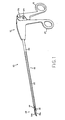
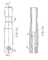
- Fig. 1 illustrates an embodiment of the endoscopic surgical instrument 10.
- the device comprises a handle assembly 12 which consists of a stationary handle 14 and a pivoting handle 16. Extending from the handle assembly is a body portion 18 which comprises an outer tubular member 20 through which a slidable inner rod member 22 passes in coaxial relationship.
- the outer tube 20 is secured to the stationary handle 14, while the inner rod 22 is secured to pivoting handle 16 at rotatable connection point 26.
- Handle 16 pivots about pivot point 24 to move in relation to stationary handle 14.
- a tool mechanism 28 Attached at a distal end of the body portion 18 is a tool mechanism 28, which essentially consists of a lower jaw member 30A and an upper jaw member 30B.
- the tool mechanism is connected to the body portion 18 at pivot point 32 and moves in a reciprocating manner about pivot point 32 through the provision of linkage mechanism 34.
- Linkage mechanism 34 will be described in greater detail below.
- connection point 26 In use, as pivoting handle 16 pivots about pivot point 24 in relation to stationary handle 14, inner rod 22 reciprocatingly slides within outer tube 20 in response to the push or pull force at connection point 26.
- connection point 26 The function of connection point 26 will be described in greater detail below.
- Jaw members 30A and 30B may comprise scissors, dissecting jaws, or a grasping mechanism, or any other tool mechanism required for specific surgical procedures.
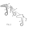
- pivoting handle 16 is provided with a pair of stop members 36A and 36B which cooperate with boss members 38A and 38B, respectively, to limit the rotational movement about pivot point 24 of the pivoting handle 16.
- the stop members are positioned on opposite sides of pivot point 24 so that when pivoting handle 16 is moved away from stationary handle 14, proximal stop 36A contacts boss 38A to limit the actual rotation of handle 16.
- distal stop 36B contacts boss 38B to limit the rotation of handle 16 in that direction.
- the stop members are provided to prevent the application of excessive forces on the tool mechanism during opening and closing of the surgical instrument. In this manner, the possibility of damage or destruction of the tool mechanism is greatly reduced or eliminated.
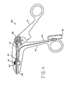
- FIG. 3 illustrates a first alternate embodiment 10A of the endoscopic surgical instrument of the present invention.
- Instrument 10A is similar to instrument 10 except for the provision of an electrocautery connection to allow for cauterization of tissue at the surgical site during the surgical procedure.
- Stationary handle 14 is provided with a connection port 42 for the reception of an electrical jack member (not shown) for providing the necessary current to the tool.
- a leaf spring 44 electrically connects port 42 with outer tube member 20 which carries the electric current to the tool mechanism at the surgical site.
- the leaf spring is provided with a connection member 46 at the port 42 and a connection member 48 at the outer tube.
- the connection members essentially rely on the resiliency of the material which comprises the leaf spring, but of course may be any conventional electrical connection.
- the handle is preferably constructed of a rigid plastic material which renders the device lightweight and electrically insulated.
- an insulation member 40 is provided on outer tube 20, the insulation member preferably consisting of heat shrink tubing. Heat shrink tubing 40 passes into stationary handle 14 to prevent the possibility of electric shock.
- connection port 42 is shown as being attached to stationary handle 14 at the finger grip, it is also contemplated to position the connection port on top of the handle as shown and described below in relation to Fig. 5.
- the positioning of the connection port in the present invention is such so as to provide the surgeon with an unobstructed line of sight down body member 18 to view the surgical site at the tool mechanism 28.
- Fig. 4 illustrates a preferred embodiment of the invention, in which the instrument 10B is provided with the electrocautery feature as well as having provisions for a rotatable body portion 18.
- a slot 54 is provided in stationary handle member 14 which passes completely through the handle member.
- a rotatable knob 52 Positioned within the slot 54 is a rotatable knob 52 which is fixedly secured to outer tube 20 through the provision of a bushing member 56.
- the rotatable knob 52 and bushing member 56 will be described in greater detail below.
- inner rod member 22 is connected to pivoting handle 16 through the provision of a rotational bushing 58.
- Bushing 58 pivots during movement of pivoting handle 16 so that as rod member 22 is reciprocated within tube 20, the bushing member 58 rotates to minimize or eliminate any radial movement of rod 22, to insure that rod 22 moves in a longitudinal direction only. This alleviates excessive torquing forces on rod member 22 as well as unwanted excessive forces at the connection point 26 to prevent damage to the handle or the inner rod member 22.
- rotational bushing member 58 Another feature provided by this rotational bushing member 58, is that by greatly reducing or eliminating radial movement of rod member 22, exact tolerances between the outer tube 20 and the inner rod member 22 may be maintained, so that less spacing is required and the instrument may be made in a smaller size than conventional endoscopic instruments. In addition, by greatly reducing or eliminating the radial deflection, the precision of the instrument is greatly enhanced.
- the features of rotational bushing member 58 will be described in greater detail below.
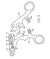
- FIG. 5 shows handle member 14A in a side cutaway view, and is the preferred embodiment of the present invention.
- handle member 14A and handle member 16A are attached at pivot point 24 so that during opening and closing of the handle assembly, proximal stop member 36A contacts boss 38A to limit rotation of pivoting handle 16A away from stationary handle 14A.
- stop member 36B contacts boss member 38B to limit rotation in that direction.
- Locking mechanism 64A and 64B may be utilized to position the handles at various locations during the opening and closing procedure, which of course allows for the application of various closing forces on the tool mechanism at the distal end of the instrument.
- Handle 14A is provided with a slot 54 which accepts the rotatable knob 52.
- a polygonal shaped boss structure 57 is provided in the handle which will accept the corresponding polygonal shape of bushing member 56 when the instrument is constructed.
- the cooperation between structure 57 and bushing 56 allows for the incremental rotation of the body portion 18, and consequently the tool mechanism 28 to position the tool mechanism at various points along the rotational path.
- the number of faces presented by boss structure 57 is equivalent to the number of faces on the polygonal cross-section of bushing 56.
- each structure has 12 faces.
- Fig. 5 illustrates the preferred location of the electrical port 60, that being at the top of handle member 14A positioned at an angle to the longitudinal axis of the instrument formed by the body portion 18.
- Port 60 is preferably positioned at an angle of less than 30 to the longitudinal axis, and in its most optimal position, is positioned at 9 to the longitudinal axis. This affords the surgeon a clear line of sight down the longitudinal axis of the instrument to view the procedure at the surgical site.
- Port 60 accepts an electrical jack member through hole 61, and an electrical connection is made through the provision of a leaf spring member held in track 62 which connects the jack (not shown) with the outer tube member as seen at 63.
- Figs. 6A and 6B illustrate the tool mechanism which consists of, for example, a scissor mechanism including scissor blades 72 and 74.
- a housing member 66 is attached to outer tube 20, and the tool mechanism is attached to housing member 66.
- Housing member 66 is shown in detail in Figs. 11 A and 11B, in which a radial hole 67 is provided to accept pivot pin 68 to allow the tool mechanism to pivot about pin 68 during opening and closing.
- Housing member 66 is provided with a longitudinal slot 70 which allows the jaw members which comprise the tool mechanism to open and close, as best seen in Figs. 11 A and 11 B.
- stiffening members 75 may be provided on scissor blades 72 and 74 which reinforce the blades and add strength to the blades. Stiffening members 75 allow for a very thin construction for blades 72 and 74, particularly at the distal end 77. Stiffening members 75 may comprise a detent or outwardly punched region whose addition to blades 72 and 74 bias the blades towards each other to enhance the shearing function of the blades. As the blades are made thinner, the resiliency of the blade material, preferably stainless steel, titanium, or a like metal, tends to decrease, and the provision of stiffening members 75 urges the blades 72 and 74 toward each other to maintain the efficiency of the cutting action. It is also contemplated that stiffening members 75 may comprise a built up region of material, or a layer of material fastened to the blades by adhesives, solder, or the like.
- scissor blades 72 and 74 are shown in the open position whereby the handle members (not shown) are in the open position, i.e., pivoting handle 16 is moved away from stationary handle 14.
- scissor blades 72 and 74 are provided with cam slots 76 and 78, which slots accept a bearing post 80 which is attached to inner rod 22.
- bearing post 80 slides within cam slots 76 and 78 to pivot blades 72 and 74 about stationary pivot point 68 to open and close the blades.
- the tail end of the blades pass through slot 70 in housing member 66 to allow the blades to open.
- Fig. 7 illustrates an exploded perspective view of a dissector device which may comprise tool mechanism 28.
- outer tube 20 is provided with a slot 21 which allows for the opening and closing of the dissector members.
- housing member 66 is eliminated.
- the dissector members 82 and 84 are provided with a cam slot arrangement similar to the device illustrated in Fig. 6B.
- Cam slot 86 is provided on upper dissector member 82
- cam slot 88 is provided on lower dissector member 84.
- inner rod 22 is positioned within outer tube 20, while dissector members 82 and 84 are pivotably secured to outer tube 20 by means of pivot pin 68 which passes through hole 69 in tube 20.
- Rod 22 is secured to the cam slot arrangement through the provision of bearing post member 90.
- bearing post 90 slides in cam slots 86 and 88 to pivot the dissector members about pivot point 68 to open the members, and when the rod member 22 is slid away from the dissector mechanism, post 90 slides in cam slots 86 and 88 away from the dissector mechanism to draw the dissector members 82 and 84 into a closed position, as best seen in Fig. 9.
- Figs. 8A and 8B illustrate the preferred embodiment of the dissector device, in which the body portion has a crescent shape to facilitate grasping and tearing tissue.
- the surface of the dissector members include serrations 98 which are provided for dissecting and tearing tissue during a surgical procedure.
- Overlapping projections 94 and 96, on which cam slots 86 and 88 are formed, allow the dissector mechanism to open and close without interfering with each other.
- the spacing between projections 94 is less than the spacing between projections 96, such that projections 94 fit within projections 96.
- Slot 21 is provided on outer tube 20 allow the projections to pass outside the perimeter of tube 20 to allow the dissector mechanism to open and close.
- Figs. 10A through 10E illustrate a grasping mechanism which may be used as the tool mechanism on the endoscopic surgical instrument of the present invention.
- Figs. 10A and 10B illustrate a cooperating pair of grasping members 100 and 102 which are provided with serrations 104 to facilitate the grasping and holding of tissue.
- the body portions 100 and 102 are preferably constructed of a plastic material which is integrally molded about projection 106.
- a post member 110 is provided about which the members 100 and 102 are molded.
- Projection 106 is provided with cam slot 108 and pivot hole 109 so that the grasping mechanism may be operated in a manner similar to that previously described above in connection with the scissor mechanism and the dissector mechanism.
- Figs. 10D and 10E illustrate the grasping mechanism of Figs. 10A through 10C except where the entire mechanism is constructed of metal, such as stainless steel, titanium, cast aluminum or the like.
- Projections 112 and 114 cooperate in a manner similar to that described above for the dissector device, where projections 112 are spaced greater than the distance between the projections 114 so that projections 114 may pass between projections 112 during opening and closing of the grasping device.
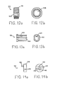
- Figs. 12 and 13 there is illustrated the rotatable knob 52 and bushing member 56 which are used in connection with the rotatable body portion to rotate the body portion and tool mechanism.
- Rotatable knob 52 is preferably knurled or provided with ridges 116 to allow for easy manipulation by the surgeon's thumb or fingers.
- Rotatable knob 52 is preferably hollow and includes a passageway 118 to allow the bushing member 56 to pass therethrough.
- Fig. 13A illustrates the bushing member as having a polygonal cross-section, such that it is provided with a series of faces 126 which cooperate with faces 125 on the rotatable bushing. The bushing extends outwardly from rotatable knob 52 (see Fig.
- Fig. 13B best illustrates boss member 124 which allows for connection and securement of the bushing to outer tube 20. Boss 124 fits into a groove or slot in tube 20 to secure the bushing and rotatable knob to outer tube 20. It is also contemplated that bushing 56 and rotatable knob 52 are constructed as a single integral unit. Knob 52 and bushing 56 are preferably constructed of plastic, so that insulation is provided during use of the electrocautery feature.
- the positioning of the rotatable knob on the stationary handle allows the surgeon to use the endoscopic surgical instrument 10B with one hand, so that as the surgeon is holding the device he may rotate the knob with his thumb while keeping his other hand free to control the surgical procedure.
- Pivot bushing 58 is best illustrated in Figs. 14A and 14B and comprises a pair of discs 128 each having a post member 130 and a hole 132 formed therein for interengaging the discs with each other. Groove 134 is provided with a notch portion 136 which accepts the end of rod member 22 which is formed with a corresponding notch. This notch secures rod 22 in place for longitudinal movement, while at the same time allowing for rotational movement. As stated above, as handle member 16 pivots, bushing 58 rotates to greatly reduce or eliminate radial deflection of the rod member within the tube. This alleviates the torquing forces on the rod and minimizes damage to the device after extended use.
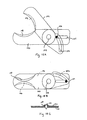
- Figs. 15A and 15B illustrate a further embodiment of the tool mechanism in accordance with the present invention.
- Stationary scissors blade 140 is attached to movable scissors blade 142 about transverse stationary pivot pin 144.
- This transverse pin 144 is attached to housing member 66 through radial hole 67 as discussed above (see Figs. 11 A and 11B).
- the present scissors embodiment utilizes a shearing motion of blades 140 and 142 in order to separate tissue.
- Arcuate cutting surfaces, 146 and 148 respectively, are formed on opposed vertical faces of the distal ends of blades 140 and 142 to better facilitate the shearing cutting action.
- a spring washer 150 see Fig. 15C, is provided to urge movable blade 142 against stationary blade 140. The urging force providing a better cutting action as the blades 140 and 142 shear against each other.
- a transverse bearing post 152 is attached to inner rod 22 and adapted for reciprocal longitudinal motion within outer tube 20.
- a longitudinal slot 154 is provided in a proximal end of stationary blade 140 in an area proximal to and in longitudinal alignment with transverse pivot pin 144.
- Bearing post 152 interfits with slot 154 for longitudinal motion therein and serves to prevent pivotal motion of blade 140 about pivot pin 144.
- An arcuate cam slot 156 is provided in a proximal end of movable blade 142 in an area proximal to transverse pivot pin 144.
- Bearing post 152 interfits within arcuate cam slot 156 and serves to translate the longitudinal motion of inner rod 22 relative to outer tube 20 into pivotal motion of blade 142 about pivot pin 144.
- blade 142 is cammed open relative to blade 140 which remains in the same longitudinal plane as rod 22.
- proximal motion of rod 22 causes bear post 152 to cam blade 142 to a closed position as shown in Fig. 15B.
- This embodiment is directed to a shearing scissors mechanism, however, other mechanisms such as, for example, graspers, dissectors, clamps etc. are contemplated.
- the endoscopic surgical instrument of the present invention is a compact, lightweight and easy to use instrument incorporating many features required during endoscopic surgical procedures which allows the surgeon to use the instrument with one hand thus freeing his other hand for other purposes during the surgery.
- the present instrument overcomes many of the disadvantages encountered with prior art devices and provides a precision instrument which is easy to handle and simple to manufacture. While the invention has been particularly shown and described with reference to the preferred embodiments, it will be understood by those skilled in the art that various modifications in form and detail may be made therein without departing from the scope and spirit of the invention. Accordingly, modifications such as those suggested above, but not limited thereto, are to be considered within the scope of the invention.
Abstract
Description
- The present invention relates to endoscopic surgical instruments, and more particularly relates to an endoscopic instrument having reciprocating jaw members which pivot in response to the opening and closing of a handle member, where the movement of the handles is translated through an elongated tubular body member to open and close the jaw mechanism.
- The present invention further provides a device in which the jaw mechanism may comprise cutting scissor blades, a gripping device for holding tissue during surgery, holding surgical needles and the like. The device of the present invention may be provided with a rotatable tubular body for selectively positioning the angle at which the jaw mechanism operates, and provision is also made for the use of electrocautery capabilities to provide for cauterization at the surgical site.
- In the prior art, various endoscopic surgical instruments are disclosed which utilize generally complex mechanisms for opening and closing handle members and jaw members to facilitate use of the device at a surgical site. Many devices provide an intricate construction in which a linkage mechanism for opening and closing the jaws requires numerous moving parts, while a sliding arrangement is provided between two extended rod members which activates the linkage mechanism in response to movement of the handle members. In addition, pivoting of the handle members in many cases causes an unwanted radial torquing force on the rod which requires additional space to be provided in the handle members to accommodate the radial movement of the rod.
- Endoscopic devices presently in use include many devices having an interchangeable shaft assembly and jaw mechanism in which a common handle may be used with a series of instruments. However, these devices suffer disadvantages in that the connecting mechanism oftentimes obstructs the view of the surgeon, and the integrity of the device is decreased due to loosening of the connection. These disadvantages are critical due to the fact that an endoscopic surgical procedure requires precision instruments with tolerances that are carefully monitored. As the connections wear, precision is sacrificed, and the usefulness of the tool is diminished.
- Greenberg, U.S. Patent No. 4,674,501 discloses a surgical instrument having a pair of reciprocating shafts which are provided with a rotational indexing knob in which the shafts are allowed to rotate to position a cutting tool at a specific angle to the handles. The shafts slide on top of each other in response to opening and closing of the handle members to open and close the jaw members of the cutting instrument. The housing is secured to a stationary handle, such that the shaft assembly rotates with the indexing knob. One shaft is secured in a ball and socket joint to a movable handle which facilitates the sliding arrangement of the movable shaft over a stationary shaft. The handle assembly is disengagable from the housing by means of a screw, and the ball joint slides out of the socket to remove the handles. This type of device is subject to the disadvantage disclosed above, in which the integrity of the device is compromised due to the number of moving parts, as well as to the fact that the ball and socket joint is an inherently loose connection which will deteriorate during continued use.
- Ger, U.S. Patent No. 4,919,152, discloses a clip applying device having a stationary handle and a pivoting handle to which an elongated shaft arrangement is attached. At the end of the shaft is a pair of reciprocating jaw members which are operated in response to pivoting movement of the handles. An inner shaft member is attached to the pivoting handle, the shaft member passing through an outer tube member which is attached to the stationary handle. As the rod member passes through the stationary handle, as well as through the outer tube at the location it is attached to the stationary handle, radial movement of the rod within the outer tube must be accounted for since the rod is attached to the stationary handle at a non- movable point. In relation to this, the bushing member is necessary inside the stationary handle to accommodate the radial play in the rod member during opening and closing of the handles.
- Straub et al., U.S. Patent No. 4,590,936, discloses a microsurgical instrument having a complex gear mechanism for translating movement of the handles to an opening and closing movement of the jaw members. A helical slot is provided in a shaft member which allows a pin to move through the slot to move the jaw members. Furthermore, a ball and socket joint is provided in the movable handle to connect the movable handle to the inner rod.
- Bauer, U.S. Patent No. 4,128,099, discloses a forceps device having an attachment for cauterization which conducts current through the outer tube to the jaw mechanism. A complex insulation system is provided to insulate the handle from the shaft, as well as to insulate the shaft itself. This device suffers the disadvantage that in order to insulate the handle, the rod member is secured to an insulating bushing, and a second rod is provided to the bushing to connect to the handle members. Furthermore, the connection point for the electrical connector is positioned in an area which will obstruct the view of the surgeon as he looks down the device to a surgical site.
- The novel endoscopic surgical instrument pursuant to the present invention obviates the disadvantages encountered in the prior art and provides a precise instrument which is easy to manufacture and efficient to use, which eliminates many of the moving parts required by prior art devices. The instrument of the present invention incorporates many features which are of use to the surgeon during an operation, while it maintains a lightweight construction in an easy to handle device in which all the features may be operated with one hand. Furthermore, the features are so positioned so as to provide a maximum line of sight for the surgeon without obstructing the view to the surgical site.
- The present invention provides a novel endoscopic surgical device which incorporates many features necessary for an endoscopic surgical procedure, and provides a lightweight and easy to use device which may be operated with one hand. The device is simple to manufacture, and may incorporate any one of a series of jaw mechanisms for various surgical procedures. The device is a high precision instrument in which many moving parts normally associated with such a device are eliminated, thus reducing instances of mechanical failure requiring expensive repair or ultimate destruction of the instrument.
- The endoscopic surgical instrument of the present invention essentially consists of a handle assembly, an elongated body assembly, and a tool mechanism attached at a distal end of the body assembly remote from the handle assembly. The handle assembly includes a stationary handle and pivoting handle, whereby the body assembly is attached to the stationary handle assembly and extends therefrom. The body assembly consists of an outer tubular member and an inner rod member which coaxially passes within the outer tubular member. The rod member is attached to the pivoting handle, while the tube member is secured in a conventional manner to the stationary handle. Preferably, the outer tube is provided with a detent which cooperates with a boss on the interior of the stationary handle to lock the outer tube in place. As the pivoting handle moves, the rod member slidably reciprocates within the outer tube member.
- Attached to a distal end of the body assembly is provided the tool mechanism which opens and closes in response to movement of the pivoting handle in relation to the stationary handle. The tool mechanism may comprise a pair of jaw members wherein one or both jaw members open and close to perform various endoscopic surgical procedures. The jaw mechanism includes, but is not limited to, a scissor device, a dissecting device, a grasping device and the like.
- In one embodiment the jaw mechanism is secured to the outer tubular member by means of a transverse post member which serves as a common pivot point about which both jaw members pivot. Each jaw member is provided with a camming portion which extends away from the pivot point, and consists of a cam slot which extends from the pivot point into the outer tube. The upper jaw is generally provided with a pair of spaced apart projections, each provided with a cam slot which transversely overlap each other. The lower jaw is also provided with a pair of extensions which are spaced apart a distance which is less than the space between the projections of the upper jaw member so that the lower projections pass between the upper projections. The lower projections are also provided with transverse overlapping slots which are positioned at an angle to the upper cam slots. The jaw mechanism is secured to the outer rod through the common pivot point.
- The inner rod member is provided with a bearing surface, which typically comprises a post member which passes through and is engaged within the cam slots of both jaw members. As the pivoting handle is moved, the rod slides through the outer tube and causes the post member to bear on the camming slots to pivot the jaw members about the common pivot point to open the jaw members. Since the cam slots are at an angle to each other, movement of the post member through the slots pivots both jaw members as the post rides through the slots. As the rod reciprocates, the jaw mechanism opens and closes.
- In order to prevent excessive forces from being applied to the jaw mechanism, the pivoting handle is provided with a pair of stop members which are positioned proximate the pivot point which secures the pivoting handle to the stationary handle, and about which the pivoting handle moves. The upper, or proximal stop member abuts a boss within the stationary handle to prevent the jaw mechanism from opening too wide, while a distal, or lower stop member abuts the stationary handle to prevent excessive forces from being applied to the jaw mechanism during closing. Accordingly, the application of force to the jaw mechanism may be regulated during design and manufacture by the interengagement of the stop members on the pivoting handle with the bosses on the stationary handle.
- A novel feature of the present invention is the provision of a second pivot point on the pivoting handle, to which the inner rod member is attached. As the handle pivots, the second pivot point rotates to allow the inner rod to move longitudinally in the outer tube with minimal radial deflection. This is an important feature of the present invention in that it reduces the radial wear on the inner rod and prevents weakening of the structure during long term use. In addition, it allows for a reduction of the required internal spacing between the outer tube and the inner rod to result in a more compact and streamlined instrument. Furthermore, unwanted torquing forces are eliminated at the pivot point thus minimizing the possibility of mechanical breakdown of the instrument at the connection between the pivoting handle and the movable inner rod.
- The present invention may also feature a connection port to provide the device with electrocautery capabilities. In this embodiment of the invention, a connection port is provided, preferably on the stationary handle on the side of the longitudinal axis opposite the finger grip portion. The connection port is positioned at an angle to the longitudinal axis, which is preferably less than 30 and in a preferred embodiment is approximately 9° to the longitudinal axis, and extends in a direction away from the body assembly. In this way, the surgeon's line of sight is unobstructed and provides a clear view to the surgical site. The connection port allows for the connection of a suitable jack member to be inserted into the device. Electrical connection between the port and the outer tube is provided by a leaf spring member which extends from the port area to the outer tube. The outer tube is provided with electrical insulation, preferably heat shrink tubing, which extends a substantial portion of the length of the outer tube. In this embodiment, the handle is molded of plastic material to provide electrical insulation to the user.
- It is also contemplated that the electrical port connection may be provided adjacent the finger grip of the stationary handle, so that the jack member extends downwardly away from the device to insure an unobstructed line of vision for the surgeon. In this case, a leaf spring member extends from the port through the stationary handle to the outer tube to complete the electrical connection.
- A further feature of the present invention is the provision of a rotatable knob on the outer tubular member to allow the body assembly and the jaw mechanism to rotate to position the jaws at desired angles to the longitudinal axis during the surgical procedure. Preferably, the rotatable knob is secured to the outer tube and positioned in a slot which passes through the stationary handle, so that a surgeon may rotate the knob, and consequently the body assembly and jaw mechanism, through the use of his thumb while he is holding the stationary handle with his fingers. This frees the surgeon's other hand to simultaneously operate another instrument during surgery.
- Preferably, the rotatable knob is secured to a bushing, which in turn is secured to the outer tube member. The bushing is provided with a polygonal cross-section, which corresponds to a boss member within the interior of the stationary handle. This allows for incremental rotation of the body assembly and jaw mechanism to desired angles to the longitudinal axis. Preferably, the bushing has a dodecahedral cross-section.
- In the preferred embodiment, all the above features are incorporated into a single endoscopic surgical instrument, so that the instrument has electrocautery and rotational capabilities. However, the instrument may be constructed without one or more of the features while still providing a lightweight precision instrument.
- Accordingly, it is an object of the present invention to provide an endoscopic surgical instrument in which all the features may be used by a surgeon with one hand.
- It is another object of the present invention to provide a lightweight endoscopic surgical instrument which provides a clear line of sight for a surgeon during a surgical procedure.
- It is a further object of the present invention to provide an endoscopic surgical instrument which prevents the application of excessive forces to the working tool mechanism to prevent damage to the instrument, whether the tool mechanism is being opened or closed.
- It is yet a further object of the present invention to provide an endoscopic surgical instrument in which tolerances between the inner slidable rod member which operates the jaws and the outer tubular member which holds the jaw mechanism are such that there is little or no radial deflection of the rod during longitudinal movement through the tube.
- It is still a further object of the present invention to provide an endoscopic surgical instrument having a handle assembly in which a first pivot point is provided for pivoting the movable handle about the stationary handle and a second pivot point is provided which connects the movable rod member to the pivoting handle which allows for rotation of the second pivot point to prevent radial deflection of the rod during longitudinal movement.
- It is yet another object of the present invention to provide an endoscopic surgical instrument having electrocautery capabilities in which the connection port for an electrical jack member is out of the line of sight of the surgeon during use.
- It is still a further object of the present invention to provide an endoscopic surgical instrument having a rotatable body member and jaw mechanism in which the rotation may be accomplished by the surgeon while using one hand.
- It is still another object of the present invention to provide an endoscopic surgical instrument having all the features above including a rotatable body assembly and jaw mechanism, electrocautery capabilities, and a rotatable pivot point for connecting the inner rod to the pivot handle to prevent radial deflection of the rod during longitudinal movement.
- The foregoing objects and other features of the invention will become more readily apparent and may be understood by referring to the following detailed description of an illustrative embodiment of the endoscopic surgical instrument, taken in conjunction with the accompanying drawings, in which:
- Fig. 1 illustrates a perspective view of an endoscopic surgical instrument in partial cutaway according to the present invention;
- Fig. 2 illustrates an exploded perspective view of a handle of an endoscopic surgical instrument according to the present invention;
- Fig. 3 illustrates a side cutaway view of an alternate embodiment of an endoscopic surgical instrument according to the present invention;
- Fig. 4 illustrates a side cutaway view of a second alternate embodiment of an endoscopic surgical instrument according to the present invention;
- Fig. 5 illustrates a side cutaway view of a handle of a preferred embodiment of an endoscopic surgical instrument according to the present invention;
- Fig. 6A shows a top cutaway view of the tool mechanism of an endoscopic surgical instrument according to the present invention;
- Fig. 6B illustrates a side cutaway view of the tool mechanism of Fig. 6A of an endoscopic surgical instrument according to the present invention;
- Fig. 7 illustrates an exploded perspective view of an alternate tool mechanism of an endoscopic surgical instrument according to the present invention;
- Fig. 8A illustrates a plan view of the upper member of a dissector mechanism for use with an endoscopic surgical instrument according to the present invention;
- Fig. 8B illustrates a plan view of a bottom member of a dissector mechanism for use with an endoscopic surgical instrument according to the present invention;
- Fig. 9 illustrates a partial cutaway side view of the dissector mechanism of Figs. 8A and 8B attached to the end of an endoscopic surgical instrument according to the present invention;
- Fig. 10A illustrates a plan view of an upper member of a molded plastic grasper mechanism;
- Fig. 10B illustrates a plan view of a bottom member of a molded plastic grasper mechanism;
- Fig. 10C illustrates a side view of a member of a grasper mechanism;
- Fig. 10D illustrates a plan view of an upper grasper member constructed of metal;
- Fig. 10E illustrates a plan view of a bottom member of a grasper mechanism constructed of metal;
- Fig. 11A illustrates a side view of a housing member of an endoscopic surgical instrument according to the present invention;
- Fig. 11 B illustrates a top cutaway view along lines A-A of Fig. 11A of a housing member of an endoscopic surgical instrument according to the present invention;
- Fig. 12A illustrates a side partial cutaway view of a rotator knob for use in an endoscopic surgical instrument of the present invention;
- Fig. 12B illustrates a front view of the rotatable knob of Fig. 12A;
- Fig. 13A illustrates a side partial cutaway view of a bushing member for use in an endoscopic surgical instrument according to the present invention;
- Fig. 13B illustrates a front view of the bushing of Fig. 13A;
- Fig. 14A illustrates a side view of a pivot bushing for use with an endoscopic surgical instrument according to the present invention;
- Fig. 14B illustrates a front view of the pivot bushing of Fig. 14A;
- Fig. 15A illustrates a side view of an open scissor mechanism in accordance with the present invention wherein only one jaw member pivots;
- Fig. 15B illustrates a side view of the scissor mechanism of Fig. 15A in the closed position; and
- Fig. 15C illustrates atop view in cross-section of the stationary pivot pin of the scissors in Fig. 15A and 15B.
- Referring now in specific detail to the drawings, in which like reference numbers identify similar or identical elements, Fig. 1 illustrates an embodiment of the endoscopic
surgical instrument 10. In its simplest form, the device comprises ahandle assembly 12 which consists of astationary handle 14 and a pivotinghandle 16. Extending from the handle assembly is abody portion 18 which comprises anouter tubular member 20 through which a slidableinner rod member 22 passes in coaxial relationship. Theouter tube 20 is secured to thestationary handle 14, while theinner rod 22 is secured to pivotinghandle 16 atrotatable connection point 26.Handle 16 pivots aboutpivot point 24 to move in relation tostationary handle 14. - Attached at a distal end of the
body portion 18 is atool mechanism 28, which essentially consists of a lower jaw member 30A and an upper jaw member 30B. The tool mechanism is connected to thebody portion 18 atpivot point 32 and moves in a reciprocating manner aboutpivot point 32 through the provision oflinkage mechanism 34.Linkage mechanism 34 will be described in greater detail below. - In use, as pivoting
handle 16 pivots aboutpivot point 24 in relation tostationary handle 14,inner rod 22 reciprocatingly slides withinouter tube 20 in response to the push or pull force atconnection point 26. The function ofconnection point 26 will be described in greater detail below. - As
rod 22 slides withintube 20, thelinkage mechanism 34 is actuated to pivot jaw members 30A and 30B aboutpivot point 32 to open and close the members. Jaw members 30A and 30B may comprise scissors, dissecting jaws, or a grasping mechanism, or any other tool mechanism required for specific surgical procedures. - As best seen in Fig. 2, pivoting
handle 16 is provided with a pair of stop members 36A and 36B which cooperate with boss members 38A and 38B, respectively, to limit the rotational movement aboutpivot point 24 of the pivotinghandle 16. The stop members are positioned on opposite sides ofpivot point 24 so that when pivotinghandle 16 is moved away fromstationary handle 14, proximal stop 36A contacts boss 38A to limit the actual rotation ofhandle 16. When handle 16 is moved towardshandle 14, distal stop 36B contacts boss 38B to limit the rotation ofhandle 16 in that direction. The stop members are provided to prevent the application of excessive forces on the tool mechanism during opening and closing of the surgical instrument. In this manner, the possibility of damage or destruction of the tool mechanism is greatly reduced or eliminated. - Turning now to Fig. 3, Fig. 3 illustrates a first alternate embodiment 10A of the endoscopic surgical instrument of the present invention. Instrument 10A is similar to
instrument 10 except for the provision of an electrocautery connection to allow for cauterization of tissue at the surgical site during the surgical procedure.Stationary handle 14 is provided with aconnection port 42 for the reception of an electrical jack member (not shown) for providing the necessary current to the tool. Aleaf spring 44 electrically connectsport 42 withouter tube member 20 which carries the electric current to the tool mechanism at the surgical site. The leaf spring is provided with aconnection member 46 at theport 42 and aconnection member 48 at the outer tube. The connection members essentially rely on the resiliency of the material which comprises the leaf spring, but of course may be any conventional electrical connection. - As the electrical charge is applied to the outer tube, it conducts along the outer tube to the tool mechanism, which in this instance is preferably a
scissor device 50 or other tool mechanism such as cautery hooks, forceps, or the like. In order to protect the surgeon who is using the device from electrical shock, the handle is preferably constructed of a rigid plastic material which renders the device lightweight and electrically insulated. - In order to prevent electrical shock during use, an
insulation member 40 is provided onouter tube 20, the insulation member preferably consisting of heat shrink tubing. Heat shrinktubing 40 passes intostationary handle 14 to prevent the possibility of electric shock. - While
connection port 42 is shown as being attached tostationary handle 14 at the finger grip, it is also contemplated to position the connection port on top of the handle as shown and described below in relation to Fig. 5. The positioning of the connection port in the present invention is such so as to provide the surgeon with an unobstructed line of sight downbody member 18 to view the surgical site at thetool mechanism 28. - Fig. 4 illustrates a preferred embodiment of the invention, in which the instrument 10B is provided with the electrocautery feature as well as having provisions for a
rotatable body portion 18. As seen in Fig. 4, aslot 54 is provided instationary handle member 14 which passes completely through the handle member. Positioned within theslot 54 is arotatable knob 52 which is fixedly secured toouter tube 20 through the provision of abushing member 56. Therotatable knob 52 andbushing member 56 will be described in greater detail below. - Also as best seen in Fig. 4,
inner rod member 22 is connected to pivotinghandle 16 through the provision of arotational bushing 58.Bushing 58 pivots during movement of pivotinghandle 16 so that asrod member 22 is reciprocated withintube 20, thebushing member 58 rotates to minimize or eliminate any radial movement ofrod 22, to insure thatrod 22 moves in a longitudinal direction only. This alleviates excessive torquing forces onrod member 22 as well as unwanted excessive forces at theconnection point 26 to prevent damage to the handle or theinner rod member 22. Another feature provided by thisrotational bushing member 58, is that by greatly reducing or eliminating radial movement ofrod member 22, exact tolerances between theouter tube 20 and theinner rod member 22 may be maintained, so that less spacing is required and the instrument may be made in a smaller size than conventional endoscopic instruments. In addition, by greatly reducing or eliminating the radial deflection, the precision of the instrument is greatly enhanced. The features ofrotational bushing member 58 will be described in greater detail below. - Turning now to Fig. 5, stationary handle 14A and pivoting handle 16A are illustrated having the provision of a locking mechanism 64A and 64B. Fig. 5 shows handle member 14A in a side cutaway view, and is the preferred embodiment of the present invention. As clearly seen in this view, handle member 14A and handle member 16A are attached at
pivot point 24 so that during opening and closing of the handle assembly, proximal stop member 36A contacts boss 38A to limit rotation of pivoting handle 16A away from stationary handle 14A. When the handles are moved towards each other, stop member 36B contacts boss member 38B to limit rotation in that direction. Locking mechanism 64A and 64B may be utilized to position the handles at various locations during the opening and closing procedure, which of course allows for the application of various closing forces on the tool mechanism at the distal end of the instrument. - Handle 14A is provided with a
slot 54 which accepts therotatable knob 52. In addition, a polygonal shapedboss structure 57 is provided in the handle which will accept the corresponding polygonal shape ofbushing member 56 when the instrument is constructed. The cooperation betweenstructure 57 andbushing 56 allows for the incremental rotation of thebody portion 18, and consequently thetool mechanism 28 to position the tool mechanism at various points along the rotational path. The number of faces presented byboss structure 57 is equivalent to the number of faces on the polygonal cross-section ofbushing 56. Preferably, each structure has 12 faces. - In addition, Fig. 5 illustrates the preferred location of the
electrical port 60, that being at the top of handle member 14A positioned at an angle to the longitudinal axis of the instrument formed by thebody portion 18.Port 60 is preferably positioned at an angle of less than 30 to the longitudinal axis, and in its most optimal position, is positioned at 9 to the longitudinal axis. This affords the surgeon a clear line of sight down the longitudinal axis of the instrument to view the procedure at the surgical site.Port 60 accepts an electrical jack member throughhole 61, and an electrical connection is made through the provision of a leaf spring member held intrack 62 which connects the jack (not shown) with the outer tube member as seen at 63. - Figs. 6A and 6B illustrate the tool mechanism which consists of, for example, a scissor mechanism including
scissor blades housing member 66 is attached toouter tube 20, and the tool mechanism is attached tohousing member 66.Housing member 66 is shown in detail in Figs. 11 A and 11B, in which aradial hole 67 is provided to acceptpivot pin 68 to allow the tool mechanism to pivot aboutpin 68 during opening and closing.Housing member 66 is provided with alongitudinal slot 70 which allows the jaw members which comprise the tool mechanism to open and close, as best seen in Figs. 11 A and 11 B. - As also shown in Fig. 6A, stiffening
members 75 may be provided onscissor blades members 75 allow for a very thin construction forblades distal end 77. Stiffeningmembers 75 may comprise a detent or outwardly punched region whose addition toblades members 75 urges theblades members 75 may comprise a built up region of material, or a layer of material fastened to the blades by adhesives, solder, or the like. - As best seen in Fig. 6B,
scissor blades handle 16 is moved away fromstationary handle 14. - As the handles move,
inner rod member 22 slides throughouter tube 20 towardsjaw mechanism 28. As seen in Fig. 6B,scissor blades cam slots post 80 which is attached toinner rod 22. Asrod 22 moves, bearingpost 80 slides withincam slots blades stationary pivot point 68 to open and close the blades. When the blades open, the tail end of the blades pass throughslot 70 inhousing member 66 to allow the blades to open. - When handle
members inner rod 22 slides away from the jaw mechanism and draws bearingpost 80 towards the handle assembly. As this occurs, bearingpost 80 slides incam slots - Turning to Fig. 7, Fig. 7 illustrates an exploded perspective view of a dissector device which may comprise
tool mechanism 28. In this embodiment,outer tube 20 is provided with aslot 21 which allows for the opening and closing of the dissector members. In this embodiment,housing member 66 is eliminated. - The
dissector members Cam slot 86 is provided onupper dissector member 82, andcam slot 88 is provided onlower dissector member 84. In this embodiment,inner rod 22 is positioned withinouter tube 20, whiledissector members outer tube 20 by means ofpivot pin 68 which passes throughhole 69 intube 20.Rod 22 is secured to the cam slot arrangement through the provision of bearingpost member 90. Asrod member 22 is slid forward withintube 20, bearingpost 90 slides incam slots pivot point 68 to open the members, and when therod member 22 is slid away from the dissector mechanism, post 90 slides incam slots dissector members - As also seen in Fig. 9, as the jaws close, the distal tips of the
jaw members - Figs. 8A and 8B illustrate the preferred embodiment of the dissector device, in which the body portion has a crescent shape to facilitate grasping and tearing tissue. The surface of the dissector members include
serrations 98 which are provided for dissecting and tearing tissue during a surgical procedure. Overlapping projections 94 and 96, on whichcam slots Slot 21 is provided onouter tube 20 allow the projections to pass outside the perimeter oftube 20 to allow the dissector mechanism to open and close. - Figs. 10A through 10E illustrate a grasping mechanism which may be used as the tool mechanism on the endoscopic surgical instrument of the present invention. Figs. 10A and 10B illustrate a cooperating pair of grasping
members serrations 104 to facilitate the grasping and holding of tissue. In the embodiment shown in Figs. 10A and 10B, thebody portions projection 106. As best seen in Fig. 10C, apost member 110 is provided about which themembers Projection 106 is provided withcam slot 108 andpivot hole 109 so that the grasping mechanism may be operated in a manner similar to that previously described above in connection with the scissor mechanism and the dissector mechanism. - Figs. 10D and 10E illustrate the grasping mechanism of Figs. 10A through 10C except where the entire mechanism is constructed of metal, such as stainless steel, titanium, cast aluminum or the like.
Projections projections 112 are spaced greater than the distance between theprojections 114 so thatprojections 114 may pass betweenprojections 112 during opening and closing of the grasping device. - Turning now to Figs. 12 and 13, there is illustrated the
rotatable knob 52 andbushing member 56 which are used in connection with the rotatable body portion to rotate the body portion and tool mechanism.Rotatable knob 52 is preferably knurled or provided withridges 116 to allow for easy manipulation by the surgeon's thumb or fingers.Rotatable knob 52 is preferably hollow and includes apassageway 118 to allow thebushing member 56 to pass therethrough. Fig. 13A illustrates the bushing member as having a polygonal cross-section, such that it is provided with a series offaces 126 which cooperate withfaces 125 on the rotatable bushing. The bushing extends outwardly from rotatable knob 52 (see Fig. 4), and faces 126 cooperate with boss structure 57 (see Fig. 5) to provide for incremental rotation of thebody portion 18 to position the tool mechanism at various points along the rotational axis. Fig. 13B best illustratesboss member 124 which allows for connection and securement of the bushing toouter tube 20.Boss 124 fits into a groove or slot intube 20 to secure the bushing and rotatable knob toouter tube 20. It is also contemplated thatbushing 56 androtatable knob 52 are constructed as a single integral unit.Knob 52 andbushing 56 are preferably constructed of plastic, so that insulation is provided during use of the electrocautery feature. - The positioning of the rotatable knob on the stationary handle allows the surgeon to use the endoscopic surgical instrument 10B with one hand, so that as the surgeon is holding the device he may rotate the knob with his thumb while keeping his other hand free to control the surgical procedure.
- As the knob is rotated, the outer tube is rotated which in turn rotates
pivot point 68, which consequently rotates the tool mechanism. Rotation of the tool mechanism causes rotation of theinner rod 22, which is accomplished withinpivot bushing 58. Pivot bushing 58 is best illustrated in Figs. 14A and 14B and comprises a pair ofdiscs 128 each having apost member 130 and ahole 132 formed therein for interengaging the discs with each other.Groove 134 is provided with anotch portion 136 which accepts the end ofrod member 22 which is formed with a corresponding notch. This notch securesrod 22 in place for longitudinal movement, while at the same time allowing for rotational movement. As stated above, ashandle member 16 pivots, bushing 58 rotates to greatly reduce or eliminate radial deflection of the rod member within the tube. This alleviates the torquing forces on the rod and minimizes damage to the device after extended use. - Figs. 15A and 15B illustrate a further embodiment of the tool mechanism in accordance with the present invention.
-
Stationary scissors blade 140 is attached tomovable scissors blade 142 about transversestationary pivot pin 144. Thistransverse pin 144 is attached tohousing member 66 throughradial hole 67 as discussed above (see Figs. 11 A and 11B). The present scissors embodiment utilizes a shearing motion ofblades blades movable blade 142 againststationary blade 140. The urging force providing a better cutting action as theblades - A
transverse bearing post 152 is attached toinner rod 22 and adapted for reciprocal longitudinal motion withinouter tube 20. Alongitudinal slot 154 is provided in a proximal end ofstationary blade 140 in an area proximal to and in longitudinal alignment withtransverse pivot pin 144. Bearingpost 152 interfits withslot 154 for longitudinal motion therein and serves to prevent pivotal motion ofblade 140 aboutpivot pin 144. - An
arcuate cam slot 156 is provided in a proximal end ofmovable blade 142 in an area proximal totransverse pivot pin 144. Bearingpost 152 interfits withinarcuate cam slot 156 and serves to translate the longitudinal motion ofinner rod 22 relative toouter tube 20 into pivotal motion ofblade 142 aboutpivot pin 144. Thus, in the embodiment shown in Figs. 15A and 15B, astransverse bear post 152 moves distally from its proximal position,blade 142 is cammed open relative toblade 140 which remains in the same longitudinal plane asrod 22. Correspondingly, proximal motion ofrod 22 causes bearpost 152 tocam blade 142 to a closed position as shown in Fig. 15B. - This embodiment is directed to a shearing scissors mechanism, however, other mechanisms such as, for example, graspers, dissectors, clamps etc. are contemplated.
- The endoscopic surgical instrument of the present invention is a compact, lightweight and easy to use instrument incorporating many features required during endoscopic surgical procedures which allows the surgeon to use the instrument with one hand thus freeing his other hand for other purposes during the surgery. The present instrument overcomes many of the disadvantages encountered with prior art devices and provides a precision instrument which is easy to handle and simple to manufacture. While the invention has been particularly shown and described with reference to the preferred embodiments, it will be understood by those skilled in the art that various modifications in form and detail may be made therein without departing from the scope and spirit of the invention. Accordingly, modifications such as those suggested above, but not limited thereto, are to be considered within the scope of the invention.
Claims (28)
wherein movement of said pivoting handle results in said rod member sliding within said tube member such that said bearing surface bears on said camming surfaces to result in said jaw members pivoting in an opening and closing manner.
each disc further having a slot for accepting and securing an end of said rod member.
Applications Claiming Priority (2)
| Application Number | Priority Date | Filing Date | Title |
|---|---|---|---|
| US59367090A | 1990-10-05 | 1990-10-05 | |
| US593670 | 1996-01-29 |
Publications (3)
| Publication Number | Publication Date |
|---|---|
| EP0484671A2 true EP0484671A2 (en) | 1992-05-13 |
| EP0484671A3 EP0484671A3 (en) | 1992-07-01 |
| EP0484671B1 EP0484671B1 (en) | 1997-03-26 |
Family
ID=24375656
Family Applications (1)
| Application Number | Title | Priority Date | Filing Date |
|---|---|---|---|
| EP91116441A Expired - Lifetime EP0484671B1 (en) | 1990-10-05 | 1991-09-26 | Endoscopic surgical instrument |
Country Status (5)
| Country | Link |
|---|---|
| US (1) | US5522830A (en) |
| EP (1) | EP0484671B1 (en) |
| JP (1) | JP3676385B2 (en) |
| CA (1) | CA2050868C (en) |
| DE (1) | DE69125338T2 (en) |
Cited By (56)
| Publication number | Priority date | Publication date | Assignee | Title |
|---|---|---|---|---|
| EP0537574A2 (en) * | 1991-10-18 | 1993-04-21 | United States Surgical Corporation | Endoscopic surgical instrument |
| EP0546264A2 (en) * | 1991-10-18 | 1993-06-16 | United States Surgical Corporation | Endoscopic surgical instrument |
| EP0567146A2 (en) * | 1992-04-23 | 1993-10-27 | United States Surgical Corporation | Articulating endoscopic surgical apparatus |
| WO1993020760A1 (en) * | 1992-04-13 | 1993-10-28 | Raychem Corporation | A surgical device |
| EP0584787A1 (en) * | 1992-08-24 | 1994-03-02 | United States Surgical Corporation | Endoscopic surgical instrument |
| EP0591859A2 (en) * | 1992-10-01 | 1994-04-13 | United States Surgical Corporation | Endoscopic surgical instrument |
| EP0593929A1 (en) * | 1992-09-23 | 1994-04-27 | United States Surgical Corporation | Surgical biopsy forceps apparatus |
| EP0594946A1 (en) * | 1992-07-22 | 1994-05-04 | Friatec Ag | Gripping and/or cutting device for endoscopic surgery |
| EP0596436A1 (en) * | 1992-11-06 | 1994-05-11 | HÜTTINGER MEDIZINTECHNIK GmbH & CO. KG | Electrosurgical instrument |
| EP0582295A3 (en) * | 1992-08-05 | 1994-05-18 | United States Surgical Corp | Articulating endoscopic surgical apparatus |
| FR2699394A1 (en) * | 1992-12-21 | 1994-06-24 | Bluet Jean Luc | Surgical needle holder. |
| WO1994020034A1 (en) * | 1993-03-10 | 1994-09-15 | Karl Storz Gmbh & Co. | Medical pliers |
| DE4323093A1 (en) * | 1993-07-10 | 1995-01-19 | Wolf Gmbh Richard | Surgical forceps |
| US5383888A (en) * | 1992-02-12 | 1995-01-24 | United States Surgical Corporation | Articulating endoscopic surgical apparatus |
| WO1995003741A2 (en) * | 1993-08-03 | 1995-02-09 | Symbiosis Corporation | Arthroscopic surgical instruments |
| US5391180A (en) * | 1991-08-05 | 1995-02-21 | United States Surgical Corporation | Articulating endoscopic surgical apparatus |
| US5439478A (en) * | 1990-05-10 | 1995-08-08 | Symbiosis Corporation | Steerable flexible microsurgical instrument with rotatable clevis |
| US5476479A (en) * | 1991-09-26 | 1995-12-19 | United States Surgical Corporation | Handle for endoscopic surgical instruments and jaw structure |
| US5478347A (en) * | 1990-10-05 | 1995-12-26 | United States Surgical Corporation | Endoscopic surgical instrument having curved blades |
| US5486189A (en) * | 1990-10-05 | 1996-01-23 | United States Surgical Corporation | Endoscopic surgical instrument |
| US5490819A (en) * | 1991-08-05 | 1996-02-13 | United States Surgical Corporation | Articulating endoscopic surgical apparatus |
| US5496347A (en) * | 1993-03-30 | 1996-03-05 | Olympus Optical Co., Ltd. | Surgical instrument |
| US5509922A (en) * | 1990-10-05 | 1996-04-23 | United States Surgical Corporation | Endoscopic surgical instrument |
| US5514157A (en) * | 1992-02-12 | 1996-05-07 | United States Surgical Corporation | Articulating endoscopic surgical apparatus |
| US5522830A (en) * | 1990-10-05 | 1996-06-04 | United States Surgical Corporation | Endoscopic surgical instrument |
| US5562682A (en) * | 1993-10-08 | 1996-10-08 | Richard-Allan Medical Industries, Inc. | Surgical Instrument with adjustable arms |
| US5626609A (en) * | 1990-10-05 | 1997-05-06 | United States Surgical Corporation | Endoscopic surgical instrument |
| US5637110A (en) * | 1995-01-31 | 1997-06-10 | Stryker Corporation | Electrocautery surgical tool with relatively pivoted tissue engaging jaws |
| EP0795301A1 (en) * | 1996-03-12 | 1997-09-17 | Ethicon Endo-Surgery, Inc. | Bipolar cutting and coagulation instrument |
| WO1997042894A1 (en) * | 1996-05-15 | 1997-11-20 | Smith & Nephew, Inc. | Electro-surgical instrument with spline connection |
| US5788710A (en) * | 1996-04-30 | 1998-08-04 | Boston Scientific Corporation | Calculus removal |
| US5797959A (en) * | 1995-09-21 | 1998-08-25 | United States Surgical Corporation | Surgical apparatus with articulating jaw structure |
| US5849022A (en) * | 1994-07-29 | 1998-12-15 | Olympus Optical Co., Ltd. | Medical instrument for use in combination with endoscopes |
| EP0916313A1 (en) * | 1997-01-07 | 1999-05-19 | Mani, Inc. | Surgical needle, needle holder, and surgical needle device |
| US6071281A (en) * | 1998-05-05 | 2000-06-06 | Ep Technologies, Inc. | Surgical method and apparatus for positioning a diagnostic or therapeutic element within the body and remote power control unit for use with same |
| US6120496A (en) * | 1998-05-05 | 2000-09-19 | Scimed Life Systems, Inc. | Surgical method and apparatus for positioning a diagnostic or therapeutic element within the body and coupling device for use with same |
| US6123702A (en) * | 1998-09-10 | 2000-09-26 | Scimed Life Systems, Inc. | Systems and methods for controlling power in an electrosurgical probe |
| US6142994A (en) * | 1994-10-07 | 2000-11-07 | Ep Technologies, Inc. | Surgical method and apparatus for positioning a diagnostic a therapeutic element within the body |
| US6152920A (en) * | 1997-10-10 | 2000-11-28 | Ep Technologies, Inc. | Surgical method and apparatus for positioning a diagnostic or therapeutic element within the body |
| US6183468B1 (en) | 1998-09-10 | 2001-02-06 | Scimed Life Systems, Inc. | Systems and methods for controlling power in an electrosurgical probe |
| US6245065B1 (en) | 1998-09-10 | 2001-06-12 | Scimed Life Systems, Inc. | Systems and methods for controlling power in an electrosurgical probe |
| US6267760B1 (en) | 1998-05-05 | 2001-07-31 | Scimed Life Systems, Inc. | Surgical method and apparatus for positioning a diagnostic or therapeutic element within the body and forming an incision in tissue with minimal blood loss |
| US6416505B1 (en) | 1998-05-05 | 2002-07-09 | Scimed Life Systems, Inc. | Surgical method and apparatus for positioning a diagnostic or therapeutic element within the body and pressure application probe for use with same |
| EP0706781B1 (en) * | 1994-10-11 | 2003-04-09 | LaserSurge, Inc. | Morcellator |
| US6692491B1 (en) | 2000-03-24 | 2004-02-17 | Scimed Life Systems, Inc. | Surgical methods and apparatus for positioning a diagnostic or therapeutic element around one or more pulmonary veins or other body structures |
| US6926712B2 (en) | 2000-03-24 | 2005-08-09 | Boston Scientific Scimed, Inc. | Clamp having at least one malleable clamp member and surgical method employing the same |
| US6932816B2 (en) | 2002-02-19 | 2005-08-23 | Boston Scientific Scimed, Inc. | Apparatus for converting a clamp into an electrophysiology device |
| US7727231B2 (en) | 2005-01-08 | 2010-06-01 | Boston Scientific Scimed, Inc. | Apparatus and methods for forming lesions in tissue and applying stimulation energy to tissue in which lesions are formed |
| US7753908B2 (en) | 2002-02-19 | 2010-07-13 | Endoscopic Technologies, Inc. (Estech) | Apparatus for securing an electrophysiology probe to a clamp |
| US7785324B2 (en) | 2005-02-25 | 2010-08-31 | Endoscopic Technologies, Inc. (Estech) | Clamp based lesion formation apparatus and methods configured to protect non-target tissue |
| US8033983B2 (en) | 2001-03-09 | 2011-10-11 | Boston Scientific Scimed, Inc. | Medical implant |
| US8162816B2 (en) | 2001-03-09 | 2012-04-24 | Boston Scientific Scimed, Inc. | System for implanting an implant and method thereof |
| US8545534B2 (en) | 2003-11-12 | 2013-10-01 | Applied Medical Resources Corporation | Overmolded grasper jaw |
| US8632453B2 (en) | 2002-12-17 | 2014-01-21 | Boston Scientific Scimed, Inc. | Spacer for sling delivery system |
| WO2017083130A1 (en) | 2015-11-13 | 2017-05-18 | Intuitive Surgical Operations, Inc. | Push-pull stapler with two degree of freedom wrist |
| KR20190106310A (en) * | 2018-03-08 | 2019-09-18 | 재단법인대구경북과학기술원 | Micro Surgical Instrument |
Families Citing this family (110)
| Publication number | Priority date | Publication date | Assignee | Title |
|---|---|---|---|---|
| US5489292A (en) | 1990-10-05 | 1996-02-06 | United States Surgical Corporation | Endoscopic surgical instrument with grip enhancing means |
| DE4341734C1 (en) * | 1993-12-08 | 1994-09-29 | Aesculap Ag | Instrument for surgical purposes |
| US5746760A (en) * | 1995-01-17 | 1998-05-05 | Laserscope | Semi-automatic tissue morcellation device |
| US7384423B1 (en) | 1995-07-13 | 2008-06-10 | Origin Medsystems, Inc. | Tissue dissection method |
| US5810805A (en) * | 1996-02-09 | 1998-09-22 | Conmed Corporation | Bipolar surgical devices and surgical methods |
| US5800448A (en) * | 1996-07-24 | 1998-09-01 | Surgical Design Corporation | Ultrasonic surgical instrument |
| JPH10127651A (en) * | 1996-09-04 | 1998-05-19 | Olympus Optical Co Ltd | Treatment tool for operation |
| US5904702A (en) * | 1997-08-14 | 1999-05-18 | University Of Massachusetts | Instrument for thoracic surgical procedures |
| US6468272B1 (en) | 1997-10-10 | 2002-10-22 | Scimed Life Systems, Inc. | Surgical probe for supporting diagnostic and therapeutic elements in contact with tissue in or around body orifices |
| US5980511A (en) * | 1998-05-15 | 1999-11-09 | T. Esser | Medical instrument handle with integral palm blocking member |
| US6830546B1 (en) | 1998-06-22 | 2004-12-14 | Origin Medsystems, Inc. | Device and method for remote vessel ligation |
| US6976957B1 (en) | 1998-06-22 | 2005-12-20 | Origin Medsystems, Inc. | Cannula-based surgical instrument and method |
| US7326178B1 (en) | 1998-06-22 | 2008-02-05 | Origin Medsystems, Inc. | Vessel retraction device and method |
| JP3693821B2 (en) * | 1998-07-24 | 2005-09-14 | オリンパス株式会社 | Endoscopy forceps |
| EP0979635A2 (en) | 1998-08-12 | 2000-02-16 | Origin Medsystems, Inc. | Tissue dissector apparatus |
| US6083150A (en) * | 1999-03-12 | 2000-07-04 | C. R. Bard, Inc. | Endoscopic multiple sample biopsy forceps |
| JP4233742B2 (en) | 1999-10-05 | 2009-03-04 | エシコン・エンド−サージェリィ・インコーポレイテッド | Connecting curved clamp arms and tissue pads used with ultrasonic surgical instruments |
| US6358268B1 (en) | 2000-03-06 | 2002-03-19 | Robert B. Hunt | Surgical instrument |
| US6506208B2 (en) | 2000-03-06 | 2003-01-14 | Robert B. Hunt | Surgical instrument |
| US6558313B1 (en) | 2000-11-17 | 2003-05-06 | Embro Corporation | Vein harvesting system and method |
| DE60226578D1 (en) * | 2001-03-05 | 2008-06-26 | Tyco Healthcare | SURGICAL APPARATUS |
| US7901398B2 (en) | 2001-12-19 | 2011-03-08 | George Stanczak | Failsafe reconfigurable surgical apparatus |
| US7361138B2 (en) | 2003-07-31 | 2008-04-22 | Scimed Life Systems, Inc. | Bioabsorbable casing for surgical sling assembly |
| US8114107B2 (en) * | 2003-11-05 | 2012-02-14 | Applied Medical Resources Corporation | Laparoscopic scissor blades |
| US8002770B2 (en) | 2003-12-02 | 2011-08-23 | Endoscopic Technologies, Inc. (Estech) | Clamp based methods and apparatus for forming lesions in tissue and confirming whether a therapeutic lesion has been formed |
| EP1838228A1 (en) * | 2005-01-19 | 2007-10-03 | Applied Medical Resources Corporation | Disposable laparoscopic instrument |
| US20070156172A1 (en) * | 2006-01-03 | 2007-07-05 | Alfredo Alvarado | Multipurpose knot pusher |
| US9770230B2 (en) | 2006-06-01 | 2017-09-26 | Maquet Cardiovascular Llc | Endoscopic vessel harvesting system components |
| EP1958572B1 (en) * | 2007-02-13 | 2011-12-21 | Arthrex, Inc. | Mid-point lock suture cutter |
| US7655004B2 (en) | 2007-02-15 | 2010-02-02 | Ethicon Endo-Surgery, Inc. | Electroporation ablation apparatus, system, and method |
| US7815662B2 (en) | 2007-03-08 | 2010-10-19 | Ethicon Endo-Surgery, Inc. | Surgical suture anchors and deployment device |
| US8075572B2 (en) * | 2007-04-26 | 2011-12-13 | Ethicon Endo-Surgery, Inc. | Surgical suturing apparatus |
| US8100922B2 (en) | 2007-04-27 | 2012-01-24 | Ethicon Endo-Surgery, Inc. | Curved needle suturing tool |
| US8568410B2 (en) | 2007-08-31 | 2013-10-29 | Ethicon Endo-Surgery, Inc. | Electrical ablation surgical instruments |
| US8262655B2 (en) | 2007-11-21 | 2012-09-11 | Ethicon Endo-Surgery, Inc. | Bipolar forceps |
| US8579897B2 (en) | 2007-11-21 | 2013-11-12 | Ethicon Endo-Surgery, Inc. | Bipolar forceps |
| US8480657B2 (en) | 2007-10-31 | 2013-07-09 | Ethicon Endo-Surgery, Inc. | Detachable distal overtube section and methods for forming a sealable opening in the wall of an organ |
| US20090112059A1 (en) | 2007-10-31 | 2009-04-30 | Nobis Rudolph H | Apparatus and methods for closing a gastrotomy |
| US8262680B2 (en) | 2008-03-10 | 2012-09-11 | Ethicon Endo-Surgery, Inc. | Anastomotic device |
| US8277475B2 (en) * | 2008-05-09 | 2012-10-02 | Applied Medical Resources Corporation | Laparoscopic scissors |
| US8771260B2 (en) | 2008-05-30 | 2014-07-08 | Ethicon Endo-Surgery, Inc. | Actuating and articulating surgical device |
| US8679003B2 (en) | 2008-05-30 | 2014-03-25 | Ethicon Endo-Surgery, Inc. | Surgical device and endoscope including same |
| US8317806B2 (en) | 2008-05-30 | 2012-11-27 | Ethicon Endo-Surgery, Inc. | Endoscopic suturing tension controlling and indication devices |
| US8070759B2 (en) | 2008-05-30 | 2011-12-06 | Ethicon Endo-Surgery, Inc. | Surgical fastening device |
| US8652150B2 (en) | 2008-05-30 | 2014-02-18 | Ethicon Endo-Surgery, Inc. | Multifunction surgical device |
| US8114072B2 (en) | 2008-05-30 | 2012-02-14 | Ethicon Endo-Surgery, Inc. | Electrical ablation device |
| US8906035B2 (en) | 2008-06-04 | 2014-12-09 | Ethicon Endo-Surgery, Inc. | Endoscopic drop off bag |
| US8403926B2 (en) | 2008-06-05 | 2013-03-26 | Ethicon Endo-Surgery, Inc. | Manually articulating devices |
| US8361112B2 (en) | 2008-06-27 | 2013-01-29 | Ethicon Endo-Surgery, Inc. | Surgical suture arrangement |
| US8888792B2 (en) | 2008-07-14 | 2014-11-18 | Ethicon Endo-Surgery, Inc. | Tissue apposition clip application devices and methods |
| US8262563B2 (en) | 2008-07-14 | 2012-09-11 | Ethicon Endo-Surgery, Inc. | Endoscopic translumenal articulatable steerable overtube |
| US8211125B2 (en) | 2008-08-15 | 2012-07-03 | Ethicon Endo-Surgery, Inc. | Sterile appliance delivery device for endoscopic procedures |
| US8529563B2 (en) | 2008-08-25 | 2013-09-10 | Ethicon Endo-Surgery, Inc. | Electrical ablation devices |
| US8241204B2 (en) | 2008-08-29 | 2012-08-14 | Ethicon Endo-Surgery, Inc. | Articulating end cap |
| US8480689B2 (en) | 2008-09-02 | 2013-07-09 | Ethicon Endo-Surgery, Inc. | Suturing device |
| US8409200B2 (en) | 2008-09-03 | 2013-04-02 | Ethicon Endo-Surgery, Inc. | Surgical grasping device |
| US8114119B2 (en) | 2008-09-09 | 2012-02-14 | Ethicon Endo-Surgery, Inc. | Surgical grasping device |
| US8337394B2 (en) | 2008-10-01 | 2012-12-25 | Ethicon Endo-Surgery, Inc. | Overtube with expandable tip |
| US8157834B2 (en) | 2008-11-25 | 2012-04-17 | Ethicon Endo-Surgery, Inc. | Rotational coupling device for surgical instrument with flexible actuators |
| US8172772B2 (en) | 2008-12-11 | 2012-05-08 | Ethicon Endo-Surgery, Inc. | Specimen retrieval device |
| US8361066B2 (en) | 2009-01-12 | 2013-01-29 | Ethicon Endo-Surgery, Inc. | Electrical ablation devices |
| US8828031B2 (en) | 2009-01-12 | 2014-09-09 | Ethicon Endo-Surgery, Inc. | Apparatus for forming an anastomosis |
| US9226772B2 (en) | 2009-01-30 | 2016-01-05 | Ethicon Endo-Surgery, Inc. | Surgical device |
| US8252057B2 (en) | 2009-01-30 | 2012-08-28 | Ethicon Endo-Surgery, Inc. | Surgical access device |
| US8037591B2 (en) | 2009-02-02 | 2011-10-18 | Ethicon Endo-Surgery, Inc. | Surgical scissors |
| JP5400444B2 (en) * | 2009-03-27 | 2014-01-29 | テルモ株式会社 | Method for manufacturing medical device and medical device |
| EP2485662B1 (en) | 2009-10-09 | 2015-09-09 | Applied Medical Resources Corporation | Single port instruments |
| US20110098704A1 (en) | 2009-10-28 | 2011-04-28 | Ethicon Endo-Surgery, Inc. | Electrical ablation devices |
| US8608652B2 (en) | 2009-11-05 | 2013-12-17 | Ethicon Endo-Surgery, Inc. | Vaginal entry surgical devices, kit, system, and method |
| US20110118731A1 (en) * | 2009-11-16 | 2011-05-19 | Tyco Healthcare Group Lp | Multi-Phase Electrode |
| US8496574B2 (en) | 2009-12-17 | 2013-07-30 | Ethicon Endo-Surgery, Inc. | Selectively positionable camera for surgical guide tube assembly |
| US8353487B2 (en) | 2009-12-17 | 2013-01-15 | Ethicon Endo-Surgery, Inc. | User interface support devices for endoscopic surgical instruments |
| US8506564B2 (en) | 2009-12-18 | 2013-08-13 | Ethicon Endo-Surgery, Inc. | Surgical instrument comprising an electrode |
| US9028483B2 (en) | 2009-12-18 | 2015-05-12 | Ethicon Endo-Surgery, Inc. | Surgical instrument comprising an electrode |
| US9005198B2 (en) | 2010-01-29 | 2015-04-14 | Ethicon Endo-Surgery, Inc. | Surgical instrument comprising an electrode |
| US8409246B2 (en) * | 2010-06-02 | 2013-04-02 | Covidien Lp | Apparatus for performing an electrosurgical procedure |
| US8663270B2 (en) | 2010-07-23 | 2014-03-04 | Conmed Corporation | Jaw movement mechanism and method for a surgical tool |
| US8734445B2 (en) | 2010-09-07 | 2014-05-27 | Covidien Lp | Electrosurgical instrument with sealing and dissection modes and related methods of use |
| CA2915912A1 (en) | 2010-09-10 | 2015-05-07 | Pivot Medical, Inc. | Method and apparatus for passing suture through tissue |
| US10098631B2 (en) | 2010-09-10 | 2018-10-16 | Pivot Medical, Inc. | Method and apparatus for passing suture through tissue |
| CN103298503A (en) | 2010-09-10 | 2013-09-11 | 皮沃特医疗公司 | Method and apparatus for passing suture through tissue |
| US8523893B2 (en) | 2010-09-30 | 2013-09-03 | Applied Medical Resources Corporation | Laparoscopic scissors |
| US10092291B2 (en) | 2011-01-25 | 2018-10-09 | Ethicon Endo-Surgery, Inc. | Surgical instrument with selectively rigidizable features |
| US9314620B2 (en) | 2011-02-28 | 2016-04-19 | Ethicon Endo-Surgery, Inc. | Electrical ablation devices and methods |
| US9254169B2 (en) | 2011-02-28 | 2016-02-09 | Ethicon Endo-Surgery, Inc. | Electrical ablation devices and methods |
| US9233241B2 (en) | 2011-02-28 | 2016-01-12 | Ethicon Endo-Surgery, Inc. | Electrical ablation devices and methods |
| WO2012125785A1 (en) | 2011-03-17 | 2012-09-20 | Ethicon Endo-Surgery, Inc. | Hand held surgical device for manipulating an internal magnet assembly within a patient |
| US9492221B2 (en) | 2011-10-20 | 2016-11-15 | Covidien Lp | Dissection scissors on surgical device |
| US9314295B2 (en) | 2011-10-20 | 2016-04-19 | Covidien Lp | Dissection scissors on surgical device |
| US8986199B2 (en) | 2012-02-17 | 2015-03-24 | Ethicon Endo-Surgery, Inc. | Apparatus and methods for cleaning the lens of an endoscope |
| US9668807B2 (en) | 2012-05-01 | 2017-06-06 | Covidien Lp | Simplified spring load mechanism for delivering shaft force of a surgical instrument |
| US9820765B2 (en) * | 2012-05-01 | 2017-11-21 | Covidien Lp | Surgical instrument with stamped double-flange jaws |
| US8968311B2 (en) | 2012-05-01 | 2015-03-03 | Covidien Lp | Surgical instrument with stamped double-flag jaws and actuation mechanism |
| US9427255B2 (en) | 2012-05-14 | 2016-08-30 | Ethicon Endo-Surgery, Inc. | Apparatus for introducing a steerable camera assembly into a patient |
| US9078662B2 (en) | 2012-07-03 | 2015-07-14 | Ethicon Endo-Surgery, Inc. | Endoscopic cap electrode and method for using the same |
| US9545290B2 (en) | 2012-07-30 | 2017-01-17 | Ethicon Endo-Surgery, Inc. | Needle probe guide |
| US10314649B2 (en) | 2012-08-02 | 2019-06-11 | Ethicon Endo-Surgery, Inc. | Flexible expandable electrode and method of intraluminal delivery of pulsed power |
| US9572623B2 (en) | 2012-08-02 | 2017-02-21 | Ethicon Endo-Surgery, Inc. | Reusable electrode and disposable sheath |
| US9277957B2 (en) | 2012-08-15 | 2016-03-08 | Ethicon Endo-Surgery, Inc. | Electrosurgical devices and methods |
| US10098527B2 (en) | 2013-02-27 | 2018-10-16 | Ethidcon Endo-Surgery, Inc. | System for performing a minimally invasive surgical procedure |
| US8986330B2 (en) * | 2013-07-12 | 2015-03-24 | Miami Instruments Llc | Aortic cross clamp |
| US10709435B2 (en) | 2016-04-20 | 2020-07-14 | Medos International Sarl | Meniscal repair devices, systems, and methods |
| USD804028S1 (en) * | 2016-06-20 | 2017-11-28 | Karl Storz Gmbh & Co. Kg | Suture retriever |
| USD804027S1 (en) * | 2016-06-20 | 2017-11-28 | Karl Storz Gmbh & Co. Kg | Suture retriever |
| US11207091B2 (en) | 2016-11-08 | 2021-12-28 | Covidien Lp | Surgical instrument for grasping, treating, and/or dividing tissue |
| US11241275B2 (en) | 2018-03-21 | 2022-02-08 | Covidien Lp | Energy-based surgical instrument having multiple operational configurations |
| US11294414B2 (en) * | 2018-04-05 | 2022-04-05 | Medos International Sàrl | Surgical instruments with rotation stop devices |
| US11304704B2 (en) | 2018-08-22 | 2022-04-19 | Covidien Lp | Surgical clip applier and ligation clips |
| EP3880095B1 (en) * | 2018-11-14 | 2023-06-28 | CONMED Corporation | Method of securing the shaft of a surgical instrument to the instrument housing |
| US11925406B2 (en) | 2020-09-14 | 2024-03-12 | Covidien Lp | End effector assemblies for surgical instruments |
Citations (5)
| Publication number | Priority date | Publication date | Assignee | Title |
|---|---|---|---|---|
| US3101715A (en) * | 1961-07-12 | 1963-08-27 | Mueller & Company V | Non-crushing clamp |
| US4712545A (en) * | 1984-04-05 | 1987-12-15 | Acufex Microsurgical, Inc. | Surgical instrument |
| DE8900376U1 (en) * | 1989-01-14 | 1989-03-09 | Storz, Martin, 7200 Tuttlingen, De | |
| DE8903782U1 (en) * | 1989-03-25 | 1989-08-24 | Storz, Karl, Dr.Med.H.C., 7200 Tuttlingen, De | |
| EP0380874A1 (en) * | 1989-01-31 | 1990-08-08 | C.R. Bard, Inc. | Disposable biopsy forceps |
Family Cites Families (74)
| Publication number | Priority date | Publication date | Assignee | Title |
|---|---|---|---|---|
| US487068A (en) * | 1892-11-29 | Parturition-shears | ||
| DE1065565B (en) * | 1959-09-17 | Augsburg Dr. med. Hanns Streifinger | Surgical grasping forceps | |
| US115735A (en) * | 1871-06-06 | Improvement in pruwjng-shears | ||
| US1754806A (en) * | 1929-09-05 | 1930-04-15 | Holland N Stevenson | Surgical instrument |
| US2002594A (en) * | 1933-03-24 | 1935-05-28 | Wappler Frederick Charles | Instrument for electro-surgical treatment of tissue |
| US2034785A (en) * | 1935-07-12 | 1936-03-24 | Wappler Frederick Charles | Endoscopic forceps |
| US2618268A (en) * | 1950-01-25 | 1952-11-18 | Eagerton E English | Surgical forceps or clamp |
| DE840884C (en) * | 1950-08-20 | 1952-06-09 | Hans A Roeder | Surgical tools for tying up bleeding vessels and laying sutures in hard-to-reach body cavities |
| US2790437A (en) * | 1955-10-12 | 1957-04-30 | Welch Allyn Inc | Surgical instrument |
| US2869549A (en) * | 1956-04-27 | 1959-01-20 | Jesse W Lochmiller | De-beaking devices |
| US3404677A (en) * | 1965-07-08 | 1968-10-08 | Henry A. Springer | Biopsy and tissue removing device |
| US3515139A (en) * | 1966-08-29 | 1970-06-02 | Codman & Shurtleff | Atraumatic clamp |
| US3446211A (en) * | 1967-11-09 | 1969-05-27 | Harold A Markham | Surgical clamp |
| US3585985A (en) * | 1968-12-16 | 1971-06-22 | Wilbur J Gould | Surgical instrument for biopsy |
| US3871379A (en) * | 1971-08-26 | 1975-03-18 | Henry C N Clarke | Laparoscopy instruments and method for suturing and ligation |
| US3840003A (en) * | 1971-11-24 | 1974-10-08 | Olympic Optical Co Ltd | Forceps assembly for removing cellular tissue from the body cavities |
| US3895636A (en) * | 1973-09-24 | 1975-07-22 | William Schmidt | Flexible forceps |
| JPS552966Y2 (en) * | 1974-02-08 | 1980-01-24 | ||
| US4054143A (en) * | 1975-04-26 | 1977-10-18 | Richard Wolf Gmbh | Single-pole coagulation forceps |
| US4005714A (en) * | 1975-05-03 | 1977-02-01 | Richard Wolf Gmbh | Bipolar coagulation forceps |
| US3964468A (en) * | 1975-05-30 | 1976-06-22 | The Board Of Trustees Of Leland Stanford Junior University | Bioptome |
| GB1486351A (en) * | 1975-06-06 | 1977-09-21 | Rocket Of London Ltd | Surgical clip applicator |
| US4049002A (en) * | 1975-07-18 | 1977-09-20 | Bio-Medicus, Inc. | Fluid conveying surgical instrument |
| US4043343A (en) * | 1975-08-01 | 1977-08-23 | Williams Robert W | Forceps |
| DE2642489C3 (en) * | 1976-09-22 | 1979-04-19 | Richard Wolf Gmbh, 7134 Knittlingen | Unipolar coagulation forceps |
| US4122856A (en) * | 1976-10-08 | 1978-10-31 | American Hospital Supply Corporation | Surgical instrument and method of assembly thereof |
| US4169476A (en) * | 1977-08-12 | 1979-10-02 | Wolf Medical Instruments Corporation | Applicator for surgical clip |
| US5133727A (en) * | 1990-05-10 | 1992-07-28 | Symbiosis Corporation | Radial jaw biopsy forceps |
| US4201213A (en) * | 1978-01-30 | 1980-05-06 | Codman & Shurtleff, Inc. | Surgical tool |
| GB2022421B (en) * | 1978-06-08 | 1982-09-15 | Wolf Gmbh Richard | Devices for obtaining tissure samples |
| US4243047A (en) * | 1979-02-07 | 1981-01-06 | Auburn Enterprises, Inc. | Instrument for taking tissue specimens |
| GB2048686B (en) * | 1979-05-15 | 1983-03-16 | Wolf Gmbh Richard | Endoscopc instrumentation apparatus |
| DE3045295A1 (en) * | 1979-05-21 | 1982-02-18 | American Cystoscope Makers Inc | Surgical instrument for an endoscope |
| FR2469912A1 (en) * | 1979-11-27 | 1981-05-29 | Abitbol Jean | Multi-purpose surgical instrument for inaccessible sites - has suction evacuation tube and blood coagulation head mounted on gripping jaws |
| US4369788A (en) * | 1980-01-31 | 1983-01-25 | Goald Harold J | Reversed forceps for microdisc surgery |
| DE3013836C2 (en) * | 1980-04-10 | 1987-10-01 | Dieter von Dipl.-Ing. 8000 München Zeppelin | Hysterectomy clamp |
| GB2086792B (en) * | 1980-11-07 | 1984-12-12 | Microsurgical Administrative S | Gripping devices |
| DE3217105C2 (en) * | 1982-05-07 | 1985-03-21 | Richard Wolf Gmbh, 7134 Knittlingen | Electrosurgical coagulation instrument |
| US4522206A (en) * | 1983-01-26 | 1985-06-11 | Dyonics, Inc. | Surgical instrument |
| US4662371A (en) * | 1983-01-26 | 1987-05-05 | Whipple Terry L | Surgical instrument |
| DE3303349A1 (en) * | 1983-02-02 | 1984-08-02 | Reinhold 7230 Schramberg Straub | SURGICAL INSTRUMENT FOR CUTTING TISSUE IN PARTICULAR CARTILAGE |
| DE8316034U1 (en) * | 1983-06-01 | 1983-09-29 | Richard Wolf Gmbh, 7134 Knittlingen | Scissor handle for exchangeable pliers bits |
| US4919152A (en) * | 1987-03-02 | 1990-04-24 | Ralph Ger | Method of closing the opening of a hernial sac |
| US4669471A (en) * | 1983-11-10 | 1987-06-02 | Olympus Optical Co., Ltd. | Forceps device for use in an endoscope |
| US4572185A (en) * | 1984-02-23 | 1986-02-25 | Mark Rich | Nonplanar surgical needle holder and related suturing method |
| ATE60704T1 (en) * | 1984-05-18 | 1991-02-15 | Harald Maslanka | SURGICAL GRIPPER. |
| DE8418993U1 (en) * | 1984-06-23 | 1984-09-20 | Richard Wolf Gmbh, 7134 Knittlingen | Medical forceps |
| DD233302A1 (en) * | 1984-12-28 | 1986-02-26 | Univ Berlin Humboldt | SAFETY BIOPSY FORCEPS |
| US4721116A (en) * | 1985-06-04 | 1988-01-26 | Schintgen Jean Marie | Retractable needle biopsy forceps and improved control cable therefor |
| DE3533423A1 (en) * | 1985-09-19 | 1987-03-26 | Wolf Gmbh Richard | APPLICATOR PLIERS FOR SURGICAL HANDLING FOR USE IN ENDOSCOPY |
| US4763668A (en) * | 1985-10-28 | 1988-08-16 | Mill Rose Laboratories | Partible forceps instrument for endoscopy |
| US4674501A (en) * | 1986-04-14 | 1987-06-23 | Greenberg I Melbourne | Surgical instrument |
| DE3629809A1 (en) * | 1986-09-02 | 1988-03-10 | Wolf Gmbh Richard | COAGULATION PLIERS |
| JPH0755222B2 (en) * | 1986-12-12 | 1995-06-14 | オリンパス光学工業株式会社 | Treatment tool |
| DE3733194A1 (en) * | 1987-10-01 | 1989-04-13 | Wolf Gmbh Richard | INSTRUMENT FOR HOLDING SURGICAL NEEDLES |
| US4950273A (en) * | 1987-10-26 | 1990-08-21 | Briggs Jeffrey M | Cable action instrument |
| DE3736150A1 (en) * | 1987-10-26 | 1989-05-03 | Wolf Gmbh Richard | PLIERS, ESPECIALLY HOOK PUNCH |
| US4872456A (en) * | 1987-11-12 | 1989-10-10 | Hasson Harrith M | Template incision device |
| DE3802651C2 (en) * | 1988-01-29 | 2001-03-29 | Storz Karl Gmbh & Co Kg | Medical forceps, in particular arthroscopic forceps |
| US4887612A (en) * | 1988-04-27 | 1989-12-19 | Esco Precision, Inc. | Endoscopic biopsy forceps |
| DE3824910C2 (en) * | 1988-07-22 | 1994-06-09 | Wolf Gmbh Richard | Arthroscopy hook punch |
| US4877026A (en) * | 1988-07-22 | 1989-10-31 | Microline Inc. | Surgical apparatus |
| DE8809501U1 (en) * | 1988-07-26 | 1988-11-24 | Schad, Karl, 7201 Kolbingen, De | |
| US4986825A (en) * | 1988-10-11 | 1991-01-22 | Concept, Inc. | Surgical cutting instrument |
| US5052402A (en) * | 1989-01-31 | 1991-10-01 | C.R. Bard, Inc. | Disposable biopsy forceps |
| US5009661A (en) * | 1989-04-24 | 1991-04-23 | Michelson Gary K | Protective mechanism for surgical rongeurs |
| EP0487645B1 (en) * | 1989-08-16 | 1995-12-13 | Raychem Corporation | A device for grasping or cutting an object |
| US4994025A (en) * | 1989-08-29 | 1991-02-19 | Baxter International Inc. | Method of dissolving cholesterol-rich calculi with short chain halogenated organic solvents and cosolvents |
| US5171256A (en) * | 1990-05-10 | 1992-12-15 | Symbiosis Corporation | Single acting disposable laparoscopic scissors |
| US5152780A (en) * | 1990-05-31 | 1992-10-06 | Tnco, Inc. | Micro-instrument |
| CA2050868C (en) * | 1990-10-05 | 2002-01-01 | Ernie Aranyi | Endoscopic surgical instrument |
| FR2668697B1 (en) * | 1990-11-06 | 1997-06-06 | Ethnor | DISSECTOR, ESPECIALLY FOR ENDOSCOPIC SURGERY. |
| DE9106506U1 (en) * | 1991-05-27 | 1991-07-25 | Storz, Karl, Dr.Med.H.C., 7200 Tuttlingen, De | |
| DE9109097U1 (en) * | 1991-07-24 | 1991-09-19 | Klemm, Bernd, 7801 Umkirch, De |
-
1991
- 1991-09-06 CA CA002050868A patent/CA2050868C/en not_active Expired - Lifetime
- 1991-09-26 EP EP91116441A patent/EP0484671B1/en not_active Expired - Lifetime
- 1991-09-26 DE DE69125338T patent/DE69125338T2/en not_active Expired - Lifetime
- 1991-10-04 JP JP25811291A patent/JP3676385B2/en not_active Expired - Lifetime
-
1994
- 1994-06-03 US US08/253,826 patent/US5522830A/en not_active Expired - Lifetime
Patent Citations (5)
| Publication number | Priority date | Publication date | Assignee | Title |
|---|---|---|---|---|
| US3101715A (en) * | 1961-07-12 | 1963-08-27 | Mueller & Company V | Non-crushing clamp |
| US4712545A (en) * | 1984-04-05 | 1987-12-15 | Acufex Microsurgical, Inc. | Surgical instrument |
| DE8900376U1 (en) * | 1989-01-14 | 1989-03-09 | Storz, Martin, 7200 Tuttlingen, De | |
| EP0380874A1 (en) * | 1989-01-31 | 1990-08-08 | C.R. Bard, Inc. | Disposable biopsy forceps |
| DE8903782U1 (en) * | 1989-03-25 | 1989-08-24 | Storz, Karl, Dr.Med.H.C., 7200 Tuttlingen, De |
Cited By (83)
| Publication number | Priority date | Publication date | Assignee | Title |
|---|---|---|---|---|
| US5439478A (en) * | 1990-05-10 | 1995-08-08 | Symbiosis Corporation | Steerable flexible microsurgical instrument with rotatable clevis |
| US5478347A (en) * | 1990-10-05 | 1995-12-26 | United States Surgical Corporation | Endoscopic surgical instrument having curved blades |
| US5486189A (en) * | 1990-10-05 | 1996-01-23 | United States Surgical Corporation | Endoscopic surgical instrument |
| US5522830A (en) * | 1990-10-05 | 1996-06-04 | United States Surgical Corporation | Endoscopic surgical instrument |
| US5509922A (en) * | 1990-10-05 | 1996-04-23 | United States Surgical Corporation | Endoscopic surgical instrument |
| US5626609A (en) * | 1990-10-05 | 1997-05-06 | United States Surgical Corporation | Endoscopic surgical instrument |
| US5391180A (en) * | 1991-08-05 | 1995-02-21 | United States Surgical Corporation | Articulating endoscopic surgical apparatus |
| US5490819A (en) * | 1991-08-05 | 1996-02-13 | United States Surgical Corporation | Articulating endoscopic surgical apparatus |
| US5476479A (en) * | 1991-09-26 | 1995-12-19 | United States Surgical Corporation | Handle for endoscopic surgical instruments and jaw structure |
| EP0546264A2 (en) * | 1991-10-18 | 1993-06-16 | United States Surgical Corporation | Endoscopic surgical instrument |
| EP0546264A3 (en) * | 1991-10-18 | 1993-12-22 | United States Surgical Corp | Endoscopic surgical instrument |
| EP0537574A2 (en) * | 1991-10-18 | 1993-04-21 | United States Surgical Corporation | Endoscopic surgical instrument |
| EP0537574A3 (en) * | 1991-10-18 | 1994-07-27 | United States Surgical Corp | Endoscopic surgical instrument |
| US5383888A (en) * | 1992-02-12 | 1995-01-24 | United States Surgical Corporation | Articulating endoscopic surgical apparatus |
| US5607450A (en) * | 1992-02-12 | 1997-03-04 | United States Surgical Corporation | Articulating endoscopic surgical apparatus |
| US5514157A (en) * | 1992-02-12 | 1996-05-07 | United States Surgical Corporation | Articulating endoscopic surgical apparatus |
| US5782859A (en) * | 1992-02-12 | 1998-07-21 | United States Surgical Corporation | Articulating endoscopic surgical apparatus |
| WO1993020760A1 (en) * | 1992-04-13 | 1993-10-28 | Raychem Corporation | A surgical device |
| EP0567146A3 (en) * | 1992-04-23 | 1994-06-08 | United States Surgical Corp | Articulating endoscopic surgical apparatus |
| US5403342A (en) * | 1992-04-23 | 1995-04-04 | United States Surgical Corporation | Articulating endoscopic surgical apparatus |
| US5417203A (en) * | 1992-04-23 | 1995-05-23 | United States Surgical Corporation | Articulating endoscopic surgical apparatus |
| EP0567146A2 (en) * | 1992-04-23 | 1993-10-27 | United States Surgical Corporation | Articulating endoscopic surgical apparatus |
| EP0594946A1 (en) * | 1992-07-22 | 1994-05-04 | Friatec Ag | Gripping and/or cutting device for endoscopic surgery |
| EP0582295A3 (en) * | 1992-08-05 | 1994-05-18 | United States Surgical Corp | Articulating endoscopic surgical apparatus |
| EP0584787A1 (en) * | 1992-08-24 | 1994-03-02 | United States Surgical Corporation | Endoscopic surgical instrument |
| EP0593929A1 (en) * | 1992-09-23 | 1994-04-27 | United States Surgical Corporation | Surgical biopsy forceps apparatus |
| EP0591859A3 (en) * | 1992-10-01 | 1994-05-18 | United States Surgical Corp | Endoscopic surgical instrument |
| EP0591859A2 (en) * | 1992-10-01 | 1994-04-13 | United States Surgical Corporation | Endoscopic surgical instrument |
| EP0596436A1 (en) * | 1992-11-06 | 1994-05-11 | HÜTTINGER MEDIZINTECHNIK GmbH & CO. KG | Electrosurgical instrument |
| WO1994014381A1 (en) * | 1992-12-21 | 1994-07-07 | Yves Leclerc | Surgical needle-holder for endoscopic suture ou ligature |
| FR2699394A1 (en) * | 1992-12-21 | 1994-06-24 | Bluet Jean Luc | Surgical needle holder. |
| WO1994020034A1 (en) * | 1993-03-10 | 1994-09-15 | Karl Storz Gmbh & Co. | Medical pliers |
| DE4307539B4 (en) * | 1993-03-10 | 2005-08-25 | Karl Storz Gmbh & Co. Kg | Medical forceps |
| US5817128A (en) * | 1993-03-10 | 1998-10-06 | Karl Storz Gmbh & Co. | Medical tongs |
| US5496347A (en) * | 1993-03-30 | 1996-03-05 | Olympus Optical Co., Ltd. | Surgical instrument |
| DE4323093A1 (en) * | 1993-07-10 | 1995-01-19 | Wolf Gmbh Richard | Surgical forceps |
| WO1995003741A3 (en) * | 1993-08-03 | 1995-03-16 | Symbiosis Corp | Arthroscopic surgical instruments |
| WO1995003741A2 (en) * | 1993-08-03 | 1995-02-09 | Symbiosis Corporation | Arthroscopic surgical instruments |
| US5562682A (en) * | 1993-10-08 | 1996-10-08 | Richard-Allan Medical Industries, Inc. | Surgical Instrument with adjustable arms |
| US5849022A (en) * | 1994-07-29 | 1998-12-15 | Olympus Optical Co., Ltd. | Medical instrument for use in combination with endoscopes |
| US6142994A (en) * | 1994-10-07 | 2000-11-07 | Ep Technologies, Inc. | Surgical method and apparatus for positioning a diagnostic a therapeutic element within the body |
| US6425895B1 (en) | 1994-10-07 | 2002-07-30 | Ep Technologies, Inc. | Surgical apparatus for positioning a diagnostic or therapeutic element within the body |
| EP0706781B1 (en) * | 1994-10-11 | 2003-04-09 | LaserSurge, Inc. | Morcellator |
| US5637110A (en) * | 1995-01-31 | 1997-06-10 | Stryker Corporation | Electrocautery surgical tool with relatively pivoted tissue engaging jaws |
| US5797959A (en) * | 1995-09-21 | 1998-08-25 | United States Surgical Corporation | Surgical apparatus with articulating jaw structure |
| EP0795301A1 (en) * | 1996-03-12 | 1997-09-17 | Ethicon Endo-Surgery, Inc. | Bipolar cutting and coagulation instrument |
| US5957932A (en) * | 1996-04-30 | 1999-09-28 | Boston Scientific Corporation | Calculus removal |
| US6319262B1 (en) | 1996-04-30 | 2001-11-20 | Boston Scientific Corporation | Calculus removal |
| US5788710A (en) * | 1996-04-30 | 1998-08-04 | Boston Scientific Corporation | Calculus removal |
| WO1997042894A1 (en) * | 1996-05-15 | 1997-11-20 | Smith & Nephew, Inc. | Electro-surgical instrument with spline connection |
| US5989247A (en) * | 1996-05-15 | 1999-11-23 | Smith & Nephew Endoscopy Inc. | Electro-surgical instrument with spline connection |
| EP0916313A4 (en) * | 1997-01-07 | 2006-04-12 | Mani Inc | Surgical needle, needle holder, and surgical needle device |
| EP0916313A1 (en) * | 1997-01-07 | 1999-05-19 | Mani, Inc. | Surgical needle, needle holder, and surgical needle device |
| US6152920A (en) * | 1997-10-10 | 2000-11-28 | Ep Technologies, Inc. | Surgical method and apparatus for positioning a diagnostic or therapeutic element within the body |
| US6416505B1 (en) | 1998-05-05 | 2002-07-09 | Scimed Life Systems, Inc. | Surgical method and apparatus for positioning a diagnostic or therapeutic element within the body and pressure application probe for use with same |
| US6071281A (en) * | 1998-05-05 | 2000-06-06 | Ep Technologies, Inc. | Surgical method and apparatus for positioning a diagnostic or therapeutic element within the body and remote power control unit for use with same |
| US6267760B1 (en) | 1998-05-05 | 2001-07-31 | Scimed Life Systems, Inc. | Surgical method and apparatus for positioning a diagnostic or therapeutic element within the body and forming an incision in tissue with minimal blood loss |
| US6120496A (en) * | 1998-05-05 | 2000-09-19 | Scimed Life Systems, Inc. | Surgical method and apparatus for positioning a diagnostic or therapeutic element within the body and coupling device for use with same |
| US6488679B1 (en) | 1998-09-10 | 2002-12-03 | Scimed Life Systems, Inc. | Systems and methods for controlling power in an electrosurgical probe |
| US6494880B1 (en) | 1998-09-10 | 2002-12-17 | Scimed Life Systems, Inc. | Systems and methods for controlling power in an electrosurgical probe |
| US6245065B1 (en) | 1998-09-10 | 2001-06-12 | Scimed Life Systems, Inc. | Systems and methods for controlling power in an electrosurgical probe |
| US7582084B2 (en) | 1998-09-10 | 2009-09-01 | Boston Scientific Scimed, Inc. | Systems and methods for controlling power in an electrosurgical probe |
| US6183468B1 (en) | 1998-09-10 | 2001-02-06 | Scimed Life Systems, Inc. | Systems and methods for controlling power in an electrosurgical probe |
| US6123702A (en) * | 1998-09-10 | 2000-09-26 | Scimed Life Systems, Inc. | Systems and methods for controlling power in an electrosurgical probe |
| US6926712B2 (en) | 2000-03-24 | 2005-08-09 | Boston Scientific Scimed, Inc. | Clamp having at least one malleable clamp member and surgical method employing the same |
| US6692491B1 (en) | 2000-03-24 | 2004-02-17 | Scimed Life Systems, Inc. | Surgical methods and apparatus for positioning a diagnostic or therapeutic element around one or more pulmonary veins or other body structures |
| US8033983B2 (en) | 2001-03-09 | 2011-10-11 | Boston Scientific Scimed, Inc. | Medical implant |
| US8617048B2 (en) | 2001-03-09 | 2013-12-31 | Boston Scientific Scimed, Inc. | System for implanting an implant and method thereof |
| US8162816B2 (en) | 2001-03-09 | 2012-04-24 | Boston Scientific Scimed, Inc. | System for implanting an implant and method thereof |
| US6932816B2 (en) | 2002-02-19 | 2005-08-23 | Boston Scientific Scimed, Inc. | Apparatus for converting a clamp into an electrophysiology device |
| US8585701B2 (en) | 2002-02-19 | 2013-11-19 | Estech, Inc. (Endoscopic Technologies, Inc.) | Apparatus for securing an electrophysiology probe to a clamp |
| US7753908B2 (en) | 2002-02-19 | 2010-07-13 | Endoscopic Technologies, Inc. (Estech) | Apparatus for securing an electrophysiology probe to a clamp |
| US8241277B2 (en) | 2002-02-19 | 2012-08-14 | Endoscopic Technologies, Inc. (Estech) | Apparatus for securing an electrophysiology probe to a clamp |
| US8632453B2 (en) | 2002-12-17 | 2014-01-21 | Boston Scientific Scimed, Inc. | Spacer for sling delivery system |
| US8545534B2 (en) | 2003-11-12 | 2013-10-01 | Applied Medical Resources Corporation | Overmolded grasper jaw |
| US9161770B2 (en) | 2003-11-12 | 2015-10-20 | Applied Medical Resources Corporation | Overmolded grasper jaw |
| US7727231B2 (en) | 2005-01-08 | 2010-06-01 | Boston Scientific Scimed, Inc. | Apparatus and methods for forming lesions in tissue and applying stimulation energy to tissue in which lesions are formed |
| US7785324B2 (en) | 2005-02-25 | 2010-08-31 | Endoscopic Technologies, Inc. (Estech) | Clamp based lesion formation apparatus and methods configured to protect non-target tissue |
| WO2017083130A1 (en) | 2015-11-13 | 2017-05-18 | Intuitive Surgical Operations, Inc. | Push-pull stapler with two degree of freedom wrist |
| CN108289691A (en) * | 2015-11-13 | 2018-07-17 | 直观外科手术操作公司 | Plug-type stitching unstrument with two degrees of freedom wrist |
| EP3373831A4 (en) * | 2015-11-13 | 2019-07-03 | Intuitive Surgical Operations Inc. | Push-pull stapler with two degree of freedom wrist |
| CN108289691B (en) * | 2015-11-13 | 2021-04-09 | 直观外科手术操作公司 | Push-pull type stitching instrument with two-degree-of-freedom wrist |
| KR20190106310A (en) * | 2018-03-08 | 2019-09-18 | 재단법인대구경북과학기술원 | Micro Surgical Instrument |
Also Published As
| Publication number | Publication date |
|---|---|
| EP0484671A3 (en) | 1992-07-01 |
| CA2050868C (en) | 2002-01-01 |
| CA2050868A1 (en) | 1992-04-06 |
| EP0484671B1 (en) | 1997-03-26 |
| DE69125338D1 (en) | 1997-04-30 |
| US5522830A (en) | 1996-06-04 |
| JP3676385B2 (en) | 2005-07-27 |
| DE69125338T2 (en) | 1997-08-07 |
| JPH04246344A (en) | 1992-09-02 |
Similar Documents
| Publication | Publication Date | Title |
|---|---|---|
| EP0484671B1 (en) | Endoscopic surgical instrument | |
| US5486189A (en) | Endoscopic surgical instrument | |
| US5509922A (en) | Endoscopic surgical instrument | |
| US5478347A (en) | Endoscopic surgical instrument having curved blades | |
| US5489292A (en) | Endoscopic surgical instrument with grip enhancing means | |
| US5626609A (en) | Endoscopic surgical instrument | |
| EP0584787A1 (en) | Endoscopic surgical instrument | |
| EP0589454A2 (en) | Endoscopic surgical instrument | |
| US5141519A (en) | Connecting elements for connecting push rod to end effectors in a disposable laparoscopic surgical instrument | |
| US5241968A (en) | Single acting endoscopic instruments | |
| US5281220A (en) | Endoscopic instrument | |
| US5156633A (en) | Maryland dissector laparoscopic instrument | |
| US6168605B1 (en) | Curved laparoscopic scissor having arcs of curvature | |
| US5133735A (en) | Thumb-activated actuating member for imparting reciprocal motion to push rod of a disposable laparoscopic surgical instrument | |
| US5496317A (en) | Laparoscopic surgical instrument | |
| US5133736A (en) | Investment cast end effectors for disposable laparoscopic surgical instrument | |
| US5569298A (en) | Resposable scissors | |
| US5800449A (en) | Knife shield for surgical instruments | |
| US5171256A (en) | Single acting disposable laparoscopic scissors | |
| US5275612A (en) | Insulating ferrule for disposable laparoscopic surgical instrument | |
| EP0557806A2 (en) | Articulating endoscopic surgical apparatus | |
| EP0507622B1 (en) | Endoscopic surgical instruments | |
| EP0543107B1 (en) | Endoscopic surgical instruments and jaw structure | |
| EP0537574A2 (en) | Endoscopic surgical instrument | |
| EP0546264A2 (en) | Endoscopic surgical instrument |
Legal Events
| Date | Code | Title | Description |
|---|---|---|---|
| PUAI | Public reference made under article 153(3) epc to a published international application that has entered the european phase |
Free format text: ORIGINAL CODE: 0009012 |
|
| PUAL | Search report despatched |
Free format text: ORIGINAL CODE: 0009013 |
|
| AK | Designated contracting states |
Kind code of ref document: A2 Designated state(s): DE FR GB |
|
| AK | Designated contracting states |
Kind code of ref document: A3 Designated state(s): DE FR GB |
|
| 17P | Request for examination filed |
Effective date: 19920902 |
|
| 17Q | First examination report despatched |
Effective date: 19940718 |
|
| GRAG | Despatch of communication of intention to grant |
Free format text: ORIGINAL CODE: EPIDOS AGRA |
|
| GRAH | Despatch of communication of intention to grant a patent |
Free format text: ORIGINAL CODE: EPIDOS IGRA |
|
| GRAH | Despatch of communication of intention to grant a patent |
Free format text: ORIGINAL CODE: EPIDOS IGRA |
|
| GRAA | (expected) grant |
Free format text: ORIGINAL CODE: 0009210 |
|
| AK | Designated contracting states |
Kind code of ref document: B1 Designated state(s): DE FR GB |
|
| REF | Corresponds to: |
Ref document number: 69125338 Country of ref document: DE Date of ref document: 19970430 |
|
| ET | Fr: translation filed | ||
| PLBE | No opposition filed within time limit |
Free format text: ORIGINAL CODE: 0009261 |
|
| STAA | Information on the status of an ep patent application or granted ep patent |
Free format text: STATUS: NO OPPOSITION FILED WITHIN TIME LIMIT |
|
| 26N | No opposition filed | ||
| REG | Reference to a national code |
Ref country code: GB Ref legal event code: IF02 |
|
| PGFP | Annual fee paid to national office [announced via postgrant information from national office to epo] |
Ref country code: FR Payment date: 20100930 Year of fee payment: 20 |
|
| PGFP | Annual fee paid to national office [announced via postgrant information from national office to epo] |
Ref country code: GB Payment date: 20100927 Year of fee payment: 20 |
|
| PGFP | Annual fee paid to national office [announced via postgrant information from national office to epo] |
Ref country code: DE Payment date: 20100929 Year of fee payment: 20 |
|
| REG | Reference to a national code |
Ref country code: DE Ref legal event code: R071 Ref document number: 69125338 Country of ref document: DE |
|
| REG | Reference to a national code |
Ref country code: DE Ref legal event code: R071 Ref document number: 69125338 Country of ref document: DE |
|
| REG | Reference to a national code |
Ref country code: GB Ref legal event code: PE20 Expiry date: 20110925 |
|
| PG25 | Lapsed in a contracting state [announced via postgrant information from national office to epo] |
Ref country code: GB Free format text: LAPSE BECAUSE OF EXPIRATION OF PROTECTION Effective date: 20110925 |
|
| PG25 | Lapsed in a contracting state [announced via postgrant information from national office to epo] |
Ref country code: DE Free format text: LAPSE BECAUSE OF EXPIRATION OF PROTECTION Effective date: 20110927 |