EP0484935A2 - Method and device for reading and identifying information represented by signs, in particular bar codes, in a two- or three-dimensional field using a video camera which is able te generate a binary videosignal of the image - Google Patents
Method and device for reading and identifying information represented by signs, in particular bar codes, in a two- or three-dimensional field using a video camera which is able te generate a binary videosignal of the image Download PDFInfo
- Publication number
- EP0484935A2 EP0484935A2 EP91118979A EP91118979A EP0484935A2 EP 0484935 A2 EP0484935 A2 EP 0484935A2 EP 91118979 A EP91118979 A EP 91118979A EP 91118979 A EP91118979 A EP 91118979A EP 0484935 A2 EP0484935 A2 EP 0484935A2
- Authority
- EP
- European Patent Office
- Prior art keywords
- binary
- derivative
- video signal
- image
- signal
- Prior art date
- Legal status (The legal status is an assumption and is not a legal conclusion. Google has not performed a legal analysis and makes no representation as to the accuracy of the status listed.)
- Granted
Links
Images

Classifications
-
- G—PHYSICS
- G06—COMPUTING; CALCULATING OR COUNTING
- G06K—GRAPHICAL DATA READING; PRESENTATION OF DATA; RECORD CARRIERS; HANDLING RECORD CARRIERS
- G06K7/00—Methods or arrangements for sensing record carriers, e.g. for reading patterns
- G06K7/10—Methods or arrangements for sensing record carriers, e.g. for reading patterns by electromagnetic radiation, e.g. optical sensing; by corpuscular radiation
- G06K7/10544—Methods or arrangements for sensing record carriers, e.g. for reading patterns by electromagnetic radiation, e.g. optical sensing; by corpuscular radiation by scanning of the records by radiation in the optical part of the electromagnetic spectrum
- G06K7/10821—Methods or arrangements for sensing record carriers, e.g. for reading patterns by electromagnetic radiation, e.g. optical sensing; by corpuscular radiation by scanning of the records by radiation in the optical part of the electromagnetic spectrum further details of bar or optical code scanning devices
- G06K7/1092—Methods or arrangements for sensing record carriers, e.g. for reading patterns by electromagnetic radiation, e.g. optical sensing; by corpuscular radiation by scanning of the records by radiation in the optical part of the electromagnetic spectrum further details of bar or optical code scanning devices sensing by means of TV-scanning
Definitions
- the invention relates to a method for reading and identifying the information of an image, in particular barcode, within a two- or three-dimensional field by means of a video camera, which generates a binary video signal of the image according to the preamble of claim 1; the invention also relates to a device for carrying out the method.
- Such image information recognition systems can have a reciprocating laser beam and logic circuits or software programs, by means of which the bar codes printed on the articles are optically read and the electrical signals generated by the laser are interpreted.
- a prerequisite for the known image information recognition systems is that the character of the information must be known to the reader, which means that the reader must be specifically designed for the information to be read and interpreted, whether it is, for example, alphanumeric characters or is a barcode.
- the reader For image information processing it is imperative that between the arrangement of the images or characters containing the information and the sensor receiving the information, a fixed or variable geometric assignment is ensured; For example, a laser reader must be guided across the barcode perpendicularly or almost perpendicularly to the barcode in order to ensure correct recognition of the image or the information.
- Image information recording is a mandatory requirement that the images, whether barcode or alphanumeric characters, must have a minimum contrast to their surroundings.
- the known image information recognition systems can therefore not be used to read and interpret images or characters that have contrast disturbances and / or damage to a greater or lesser extent.
- problems frequently arise, for example due to oil stains, mechanical stresses, the application of mechanical, transparent protective layers, but also due to thermal or chemical treatments in technological processes, and all of them are unavoidable in an industrial environment.
- Another problem is that three-dimensionally arranged information, for example alpha-numeric characters or bar codes etched into the surface of a metallic object, cannot be read with the known image information recognition systems.
- the invention has for its object to provide a method and an apparatus in which the information to be read and interpreted by means of a video camera in the form of a character template as such is recognized qualitatively independently of the geometric assignment of the character template to the reader and the character template itself major damage, soiling or contrast disturbances in order to be read and interpreted correctly.
- the invention is based on the object of using a video camera to correctly read and interpret a barcode which is arbitrarily arranged within a surface or in space and has faults.
- the first derivative (f '(t)) is advantageously differentiated again and also fed to a window comparator, the switching edges of the second derivative (f' '(t)) are evaluated by means of a Schmitt trigger whose output signal (c2 (t)) again differentiated and linked with the output signal (c1 (t)) of the window comparator, a flip-flop taking over the signals of the switching edges of the second derivative and performing the linking.
- the flip-flop is advantageously a JK flip-flop, the data of the Schmitt trigger with the generating edges being taken over and the sampling frequency of the binary image being greater than or equal to the sampling frequency of the video camera.
- the autocorrelation function within a local environment is calculated for a plurality of locations, a local maximum (MAX) and / or the associated direction angle (DIR) being ascertained by means of segmentation from the obtained values of the autocorrelation.
- a local maximum (MAX) and / or the associated direction angle (DIR) being ascertained by means of segmentation from the obtained values of the autocorrelation.
- an accumulation method is advantageously used in that an enclosing contour, preferably a rectangle, is specified and a directional accumulation takes place within the contour.
- the autocorrelation can be calculated for eight displacement vectors, these being selected so that they correspond to the displacement from the central point, for example a 5 ⁇ 5 environment, towards edge points.
- a cross-correlation of the measured values can be calculated with a sine curve and the phase position and thus the angle of rotation of the parallel structures can be determined from the maximum obtained in this way.
- Fields with the same or adjacent direction with a minimum amplitude are advantageously combined into objects and the center of gravity is determined for objects of a certain size; the circumscribing rectangle of the object is defined by the center of gravity parallel to the main axis as well as orthogonal to the digital lines; The number of black and white pixels is counted orthogonally to the main lines to determine the accumulated intensity distribution along the main axis of the barcode.
- the video signal (f (t)) can advantageously pass through a low-pass filter before the first derivative (f '(t)) is formed.
- the method and the device according to the invention have the advantage that contrast disturbances and damage or incompleteness of the object can be accepted to a much greater extent with the image information recognition system and the object can still be reliably recognized as such and can be interpreted.
- they may be damaged, contrast disturbances or soiling, such as cracks, oil stains, poor contrast, to a large extent, so that they can still be read and interpreted perfectly, which is not possible with the conventional methods.
- the method according to the invention when applied to barcodes, ensures that the readability is shifted as desired or rotated within wide limits in the predetermined field of view of the video camera.
- the distance between the camera and the object or barcode can be adjusted within wide limits by selecting suitable lenses; the depth of field corresponds to that of the usual photo lenses.
- moving objects can be read and interpreted in an advantageous manner, e.g. especially moving barcodes.
- a CCD shutter video camera By using a CCD shutter video camera, a sufficiently short exposure time can be achieved to adapt the method according to the invention, the relative speed of the bar code advantageously being smaller than the quotient of the minimum structure width of the bar code (mode) divided by the exposure time of the CCD Video camera should be.
- FIG. 1 A video camera 1 (TV) with an optical lens records a drawing template 2, which is, for example, a barcode, after which the resulting video signal f (t) is fed to a binary image processor 3 (BIP), the output signal BIN of which is on the one hand a correlator 4 (KOR) and on the other hand, can be fed directly to an image memory 5 (MEM).
- BIP binary image processor 3
- KOR correlator 4
- MEM image memory 5
- the outputs DIR and MAX of the correlator 4 are also connected to the image memory 5, which is connected via a bus 6 to a central processing unit 7 (CPU).
- the video camera 1 can have a line or area sensor with basically known synchronization devices (genlock), such as clock generators, among others, and can be supplemented by an electronic quick lock (shutter).
- a CCD line scan camera or a one-dimensionally deflected laser scanner can be used; the deflection in the second direction occurs either through the natural movement of the drawing template (object) or through an optical deflection system.
- a CCD matrix camera is used.
- a CCD camera is expediently used, the shutter or integration time control of which is adapted to the movement.
- FIG. 2 shows the signal processing and the structural design of the binary image processor 3.
- the video signal is first freed of high-frequency noise and possible clock disturbances by means of a low-pass filter 8.
- two differentiators 9 and 10 with an output for the first derivative f '(t) and an output for the second derivative f' '(t) of the video signal f (t) are arranged in time and the video signal is differentiated accordingly .
- the output signal c1 (t) of the window comparator 13 is passed through a delay element 14 with the delay time ⁇ 1 to the runtime compensation and then fed to a logic element 12; the use of the window comparator 13 and of the delay element 14 represent an advantageous addition to the logic module 12.
- the output signal c1 (t) of the delay element is linked within an AND gate 16 with the signal c3 (T n ) and the sum signal EN is formed:
- the EN signal only allows the switching edges to pass that meet the features a) to c), the switching edges being those points at which c2 (t) changes and thus a third derivative c3 (t) is present.
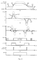
- FIG. 4a shows a black and white jump in the video signal f (t), the solid curve 21 being one with low illuminance, the dotted curve 22 being one with high illuminance and the dotted curve 25 being such in the defocused state;
- FIGS. 4b and 4c show the 1st and 2nd derivatives over time; the dotted curve 25 'in FIG. 4b means the same function in the defocused state.
- a window A-A '(FIG. 4b) is therefore formed by a threshold value decision from the first derivative, in which the contrast is evaluated and in which the zeros of the second derivative can be evaluated.
- This window is lighting-dependent, but less critical than the known direct threshold value decision in the video signal.
- the second derivative is also zero in the area of constant blackening, so that noise and other disturbances could lead to edges of the Schmitt trigger 11 here. This means that only the zeros of the 2nd derivative are evaluated, which lie above a contrast threshold that results from the 1st derivative.
- the hysteresis 26 (in FIG. 2 "H") of the Schmitt trigger 11 acts in a similar manner to suppress interference.
- the signal c2 (t) from the Schmitt trigger 11 is shown in FIG. 4d.
- the high sensitivity of the method also provides contours in the binary image with low contrast details, which are permitted or forbidden as required by selecting thresholds H and S and possibly A-A ', i.e. can be specified.
- the scanning of the binary image is carried out at a sampling frequency which can advantageously be above the pixel frequency of the video camera. This is advantageous if a higher scanning accuracy is to be achieved with sub-pixel interpolation in known image structures, for example bar codes.
- the length is determined here more precisely than the grid of the scanner actually allows.
- the gray value resolution is reduced in order to increase the length resolution, what is advantageously given up to a resolution of approximately 4: 1.
- Figures 4 e-g show the associated function of c1 (t) of the window comparator 13, as well as the signal EN (t) and the associated binary signal BIN.
- Figures 5 to 7 show the signal processing of the correlator 4 (KOR).
- the general task of the correlator 4 is to analyze the mapping structure of the object and to determine predetermined or sought structures. If it is a bar code, the task of the correlator 4 is in particular to detect parallel line structures of the bar code and to determine their direction.
- the autocorrelation function ACF is determined in a local environment ( ⁇ x. ⁇ y) of a test point (P ⁇ x0, y0 ⁇ ) within the field of view of the video camera in order to specify a dependency measure in this way.
- the ACF has characteristic maxima (displacement vector R ⁇ in the direction of the bars) and minima (displacement vector R ⁇ perpendicular to these).
- the minimum of the ACF is exactly in the direction rotated by 90 degrees to DIR (max).
- the normalized difference (KTR) a measure of contrast for existing bar code and can be used directly for the segmentation shown in FIG. 6.
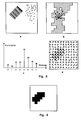
- FIG. 5 shows a possibility of selecting the support points for determining the ACF (with the same angular rotation ⁇ ), in FIG. 5 d the result of the correlation is shown.
- the local environment has the format 5x5 picture elements, of which, for reasons of symmetry, however, only the picture points above the central point need to be taken into account, for example.
- the current and two previous lines are held in shift registers, possibly with RAM support.
- the desired picture elements can be reached via taps and linked according to FIG. 5 b, wherein the outputs of the EXOR links are clocked by counters.
- the meters contain intermediate values of the ACF, which then have to be added in the vertical direction.
- the maximum MAX of the ACF is determined via a table (memory) or several hierarchically arranged comparators and multiplexers and the assigned direction (DIR) is output.
- DIR the measured values of the ACF (DIR), ie the frequencies of the occurrence of the directions, are specified.
- the values MAX, MIN and DIR are saved as a function of the coordinates of the assigned measuring fields ( ⁇ x. ⁇ y).
- the position of the bar code in the image and its angle of rotation are detected from these measurement matrices by means of threshold value decisions.
- the area in which the barcode is located is segmented, which is shown in FIG. 6. For this purpose, related objects with identical or adjacent directions are determined.
- the segmentation is used to detect parallel structures, such as barcodes, in binary images.
- the autocorrelation is calculated for 8 displacement vectors.
- the displacement vectors are chosen so that they correspond to the displacement from the central point of a 5 x 5 environment to edge points. For reasons of symmetry, only 8 of the 16 boundary points have to be taken into account:
- the overall image of, for example, 384 x 288 pixels is advantageously divided into 24 x 18 fields of 16 x 16 pixels.
- the autocorrelation is calculated for fields of 16 x 16 pixels so that the 5 x 5 surroundings are completely within the field.
- a cross correlation of the measured values with a sine curve is calculated for the exact detection of the angle of rotation.
- the maximum of the correlation becomes the phase position and thus the angle of rotation of the parallel structures are determined.
- the amplitude (difference between maximum and minimum of the correlation values) is a measure of the presence of parallel structures within the field.
- the result is a structure of size 24 x 18 with the absolute direction value and the amplitude.
- fields with the same or adjacent direction, in which the amplitude exceeds a certain threshold are combined to form objects.
- the center of gravity is determined for objects of a certain size.
- a circumscribing rectangle of the object is defined parallel to the main axis (orthogonal to the direction of the digital route through the center of gravity):
- the number of black and white pixels is counted orthogonally to the main lines. The result is the accumulated intensity distribution along the main axis of the barcode.
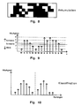
- the precise measurement of the angle of rotation of the bar code takes place within the objects by correlating image lines within the bar code field and the directional accumulation of the bar code (FIG. 8). For this purpose, a number of digital measuring lines with the calculated angle of rotation are laid within the object. The white and black pixels that lie within the object to be examined are counted separately on each of these measuring lines (FIG. 9); the measuring line is then assigned the value "white” if more white than black points have been found, otherwise black, as shown in FIG. 9.
- the ordered sequence of the measured values obtained in this way is coded run-length (FIG. 10), and run-length histograms are determined, separated for white and black, i.e. from the distribution of intensity.
- the thresholds for the lengths of the runs are determined from these histograms. This divides the white and black stripes according to their width. On the basis of this classification data, the type of the present bar code is recognized and its decoding.
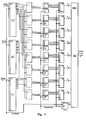
- FIG. 7 shows a possible structure of the correlator 4.
- the local environment has (2N + 1) columns and two rows; the current and the previous line are in shift registers 27, 27 ', 27''.
- the picture elements according to FIG. 5 can be linked via taps.
- the EXOR links clock downstream counter 280, 281, 282, 283, 284, 285, 286, 287, in which after the integration the ACF (x0, y0, ⁇ K , ⁇ K ) is.
- the maximum MAX of the ACF is formed via a table 29 (MUX) or staggered comparators and multiplexers and the direction DIR is switched to the output.
- the table (MUX) excludes special states, for example completely white or completely black zones, and ensures an interpolation of the direction between the nodes; the table can also be created by a hierarchical comparator arrangement.
- the object of the invention can advantageously be used industrially in image information recognition systems with which an object can still be reliably recognized and interpreted as such despite contrast disturbances, damage, soiling or incompleteness, in particular for reading and interpreting bar codes.
- the object of the invention can be used in particular in automatic reading stations and, when used for recognizing bar codes, ensures the readability of the same, displaced as desired or rotated within wide limits in the predetermined field of view of the video camera.
Abstract
Description
Die Erfindung betrifft ein Verfahren zum Lesen und Identifizieren der Information eines Bildes, insbesondere Barcode, innerhalb eines zwei- oder dreidimensionalen Feldes mittels einer Videokamera, die ein binäres Videosignal des Bildes erzeugt gemäß dem Oberbegriff des Anspruchs 1; ebenso betrifft die Erfindung eine Vorrichtung zur Durchführung des Verfahrens.The invention relates to a method for reading and identifying the information of an image, in particular barcode, within a two- or three-dimensional field by means of a video camera, which generates a binary video signal of the image according to the preamble of
Es sind Verfahren zum Lesen und Identifizieren von Bildinformationen einschließlich von Barcodes und Bildinformations-Erkennungssysteme zur Durchführung der Verfahren bekannt. Derartige Bildinformations-Erkennungssysteme können einen hin- und hergehenden Laserstrahl und logische Schaltungen bzw. Softwareprogramme aufweisen, mittels denen die auf die Artikel aufgedruckten Barcodes optisch gelesen und die erzeugten elektrischen Signale des Lasers interpretiert werden.Methods for reading and identifying image information, including bar codes, and image information recognition systems for carrying out the method are known. Such image information recognition systems can have a reciprocating laser beam and logic circuits or software programs, by means of which the bar codes printed on the articles are optically read and the electrical signals generated by the laser are interpreted.
Voraussetzung der bekannten Bildinformations-Erkennungssysteme ist, daß der Charakter der Information dem Lesegerät bekannt sein muß, was bedeutet, daß das Lesegerät in seiner Ausgestaltung spezifisch auf die zu lesende und zu interpretierende Information ausgerichtet sein muß, ob es sich beispielsweise um alphanumerische Zeichen oder um einen Barcode handelt. Zur Bildinformationsverarbeitung gehört zwingend, daß zwischen der Anordnung der die Information beinhaltenden Bilder oder Zeichen und dem die Information aufnehmenden Sensor eine feste oder nur in engen Grenzen variable geometrische Zuordnung gewährleistet ist; beispielsweise muß ein Laser-Lesegerät senkrecht oder fast senkrecht zum Barcode über denselben hinweggeführt werden, um ein einwandfreies Erkennen des Bildes bzw. der Information zu gewährleisten. Ebenso ist zur Bildinformationsaufnahme zwingende Voraussetzung, daß die Bilder, ob Barcode oder alphanumerische Zeichen, gegenüber ihrer Umgebung einen Mindestkontrast aufweisen müssen.A prerequisite for the known image information recognition systems is that the character of the information must be known to the reader, which means that the reader must be specifically designed for the information to be read and interpreted, whether it is, for example, alphanumeric characters or is a barcode. For image information processing it is imperative that between the arrangement of the images or characters containing the information and the sensor receiving the information, a fixed or variable geometric assignment is ensured; For example, a laser reader must be guided across the barcode perpendicularly or almost perpendicularly to the barcode in order to ensure correct recognition of the image or the information. Likewise, Image information recording is a mandatory requirement that the images, whether barcode or alphanumeric characters, must have a minimum contrast to their surroundings.
Mit den bekannten Bildinformations-Erkennungssystemen können deshalb Bilder odern Zeichen nicht gelesen und interpretiert werden, die in mehr oder weniger größerem Umfang Kontraststörungen und/oder Beschädigungen aufweisen. Derartige Probleme entstehen jedoch häufig, beispielsweise durch Ölflecken, mechanische Beanspruchungen, durch das Aufbringen von mechanischen, transparenten Schutzschichten, aber auch durch thermische oder chemische Behandlungen in technologischen Prozessen, und sind ihrer Gesamtheit in industrieller Umgebung unvermeidbar. Ein weiteres Problem besteht darin, daß mit den bekannten Bildinformations-Erkennungssystemen dreidimensional angeordnete Informationen, beispielsweise in die Oberfläche eines metallischen Gegenstandes geätzte alpha-numerische Zeichen oder Barcodes, nicht gelesen werden können.The known image information recognition systems can therefore not be used to read and interpret images or characters that have contrast disturbances and / or damage to a greater or lesser extent. However, such problems frequently arise, for example due to oil stains, mechanical stresses, the application of mechanical, transparent protective layers, but also due to thermal or chemical treatments in technological processes, and all of them are unavoidable in an industrial environment. Another problem is that three-dimensionally arranged information, for example alpha-numeric characters or bar codes etched into the surface of a metallic object, cannot be read with the known image information recognition systems.
Der Erfindung liegt die Aufgabe zugrunde, ein Verfahren und eine Vorrichtung zu schaffen, bei dem die mittels einer Videokamera zu lesende und zu interpretierende Information in Form von Zeichenvorlage als solche unabhängig von der geometrischen Zuordnung der Zeichenvorlage zum Lesegerät qualitativ erkannt wird und die Zeichenvorlage selbst in größerem Umfang Beschädigungen, Verschmutzungen oder Kontraststörungen aufweisen darf, um trotzdem einwandfrei gelesen und interpretiert zu werden. Insbesondere liegt der Erfindung die Aufgabe zugrunde, mittels einer Videokamera einen innerhalb einer Fläche oder im Raum beliebig angeordneten und Störungen aufweisenden Barcode einwandfrei zu lesen und zu interpretieren.The invention has for its object to provide a method and an apparatus in which the information to be read and interpreted by means of a video camera in the form of a character template as such is recognized qualitatively independently of the geometric assignment of the character template to the reader and the character template itself major damage, soiling or contrast disturbances in order to be read and interpreted correctly. In particular, the invention is based on the object of using a video camera to correctly read and interpret a barcode which is arbitrarily arranged within a surface or in space and has faults.
Die Lösung der Aufgabe besteht erfindungsgemäß in den folgenden Merkmalen:
- a) das Videosignal (f(t)) wird zweimal nach der Zeit differenziert und aus den Nullstellen der zweiten Ableitung (f''(t)) werden Schaltflanken abgeleitet, die nur dann weiterverarbeitet werden, wenn der Betrag des Videosignals der ersten Ableitung (f'(t)) eine vorgebbare Schwelle (A-A') übersteigt,
- b) die Samplingfrequenz des binären Videosignals ist größer oder gleich der Samplingfrequenz der Videokamera
- c) innerhalb einer lokalen Umgebung wird für eine Mehrzahl von Stützpunkten vom Binärsignal die Autokorrelationsfunktion berechnet und
- d) aus den erhaltenen Werten der Autokorrelationsfunktion wird
- d1) ein lokales Maximum und/oder
- d2) der zugehörige Richtungsvektor ermittelt.
- a) the video signal (f (t)) is differentiated twice according to the time and switching edges are derived from the zeros of the second derivative (f '' (t)), which only then are further processed if the amount of the video signal of the first derivative (f '(t)) exceeds a predefinable threshold (A-A'),
- b) the sampling frequency of the binary video signal is greater than or equal to the sampling frequency of the video camera
- c) within a local environment, the autocorrelation function is calculated for a plurality of support points from the binary signal and
- d) the obtained values of the autocorrelation function
- d1) a local maximum and / or
- d2) the associated direction vector is determined.
Vorteilhaft wird die erste Ableitung (f'(t)) sowohl nochmals differenziert, als auch einem Fensterkomparator zugeführt, die Schaltflanken derzweiten Ableitung (f''(t)) werden mittels eines Schmitt-Triggers ausgewertet, dessen Ausgangssignals (c₂(t)) nochmals differenziert und mit dem Ausgangssignal (c₁(t)) des Fensterkomparators verknüpft wird, wobei ein Flip-Flop die Signale der Schaltflanken der zweiten Ableitung übernimmt und die Verknüpfung durchführt. Das Flip-Flop ist vorteilhaft ein JK-Flip-Flop, wobei die Daten des Schmitt-Triggers mit den erzeugenden Flanken übernommen werden und die Samplingfrequenz des Binärbildes größer oder gleich der Samplingfrequenz der Video- kamera ist.The first derivative (f '(t)) is advantageously differentiated again and also fed to a window comparator, the switching edges of the second derivative (f' '(t)) are evaluated by means of a Schmitt trigger whose output signal (c₂ (t)) again differentiated and linked with the output signal (c₁ (t)) of the window comparator, a flip-flop taking over the signals of the switching edges of the second derivative and performing the linking. The flip-flop is advantageously a JK flip-flop, the data of the Schmitt trigger with the generating edges being taken over and the sampling frequency of the binary image being greater than or equal to the sampling frequency of the video camera.
Die Autokorrelationsfunktion innerhalb einer lokalen Umgebung wird für eine Mehrzahl von Orte berechnet, wobei mittels einer Segmentierung aus den erhaltenen Werten der Autokorrelation ein lokales Maximum (MAX) und/oder der dazugehörige Richtungswinkel (DIR) ermittelt werden. Für die Autokorrelation wird vorteilhaft ein Akkumulationsverfahren angewendet, indem eine umschlies-sende Kontur, vorzugsweise ein Rechteck, vorgegeben wird, und innerhalb der Kontur eine gerichtete Akkumulierung erfolgt. Zur Segmentierung kann zum Beispiel die Autokorrelation für acht Verschiebungsvektoren berechnet werden, wobei diese so gewählt sind, daß sie der Verschiebung vom Zentralpunkt einer beispielsweise 5x5-Umgebung zu Randpunkten hin entsprechen.The autocorrelation function within a local environment is calculated for a plurality of locations, a local maximum (MAX) and / or the associated direction angle (DIR) being ascertained by means of segmentation from the obtained values of the autocorrelation. For the autocorrelation, an accumulation method is advantageously used in that an enclosing contour, preferably a rectangle, is specified and a directional accumulation takes place within the contour. For segmentation, for example, the autocorrelation can be calculated for eight displacement vectors, these being selected so that they correspond to the displacement from the central point, for example a 5 × 5 environment, towards edge points.
Zur Detektierung des Drehwinkels kann eine Kreuzkorrelation der Meßwerte mit einer Sinuskurve berechnet und aus dem so erhaltenen Maximum die Phasenlage und somit der Drehwinkel der parallelen Strukturen ermittelt werden.To detect the angle of rotation, a cross-correlation of the measured values can be calculated with a sine curve and the phase position and thus the angle of rotation of the parallel structures can be determined from the maximum obtained in this way.
Vorteilhaft werden Felder mit gleicher oder benachbarter Richtung mit einer Mindestamplitude zu Objekten zusammengefaßt und für Objekte bestimmter Größe der Schwerpunkt ermittelt wird; das umschreibende Rechteck des Objektes wird parallel zur Hauptachse sowie orthogonal zur Richtung liegende digitale Strecken durch den Schwerpunkt definiert; orthogonal zu den Hauptstrecken werden die Anzahl der schwarzen und weißen Pixel gezählt zur Ermittlung der akkumulierten Intensitätsverteilung entlang der Hauptachse des Barcodes. In vorteilhafter Weise kann das Videosignal (f(t)) vor der Bildung der ersten Ableitung (f'(t)) ein Tiefpaßfilter durchlaufen.Fields with the same or adjacent direction with a minimum amplitude are advantageously combined into objects and the center of gravity is determined for objects of a certain size; the circumscribing rectangle of the object is defined by the center of gravity parallel to the main axis as well as orthogonal to the digital lines; The number of black and white pixels is counted orthogonally to the main lines to determine the accumulated intensity distribution along the main axis of the barcode. The video signal (f (t)) can advantageously pass through a low-pass filter before the first derivative (f '(t)) is formed.
Eine Vorrichtung zur Durchführung des Verfahrens besteht erfindungsgemäß in den folgenden Merkmalen:
- a) mittels Differenziergliedern wird das Videosignal (f(t)) zweimal nach der Zeit differenziert und aus den Nullstellen der zweiten Ableitung (f''(t)) werden Schalt-flanken abgeleitet, die nur dann weiterverarbeitet werden, wenn der Betrag des Videosignals der ersten Ableitung (f'(t)) eine vorgebbare Schwelle (A-A') übersteigt,
- b) die Samplingfrequenz des binären Videosignals ist größer oder gleich der Samplingfrequenz der Videokamera
- c) innerhalb einer lokalen Umgebung wird für eine Mehrzahl von Stützpunkten vom Binärsignal die Autokorrelationsfunktion berechnet und
- d) aus den erhaltenen Werten der Autokorrelationsfunktion wird
- d1) ein lokales Maximum und/oder
- d2) der zugehörige Richtungsvektor ermittelt.
- a) by means of differentiators, the video signal (f (t)) is differentiated twice in time and switching edges are derived from the zeros of the second derivative (f '' (t)), which are only further processed if the amount of the video signal the first derivative (f '(t)) exceeds a predefinable threshold (A-A'),
- b) the sampling frequency of the binary video signal is greater than or equal to the sampling frequency of the video camera
- c) within a local environment, the autocorrelation function is calculated for a plurality of support points from the binary signal and
- d) the obtained values of the autocorrelation function
- d1) a local maximum and / or
- d2) the associated direction vector is determined.
Das erfindungsgemäße Verfahren und die Vorrichtung besitzt den Vorteil, daß mit dem Bildinformations-Erkennungssystem in weitaus größerem Umfang Kontraststörungen und Beschädigungen oder Unvollständigkeiten des Objektes akzeptiert werden können und das Objekt trotzdem noch sicher als solches erkannt und interpretiert werden kann. Insbesondere beim Lesen und Interpretieren von Barcodes dürfen dieselben selbst in größerem Umfang Beschädigungen, Kontraststörungen oder Verschmutzungen, wie Risse, Ölflecken, Kontrastarmut, aufweisen, um trotzdem noch einwandfrei gelesen und interpretiert zu werden, was mit den herkömmlichen Verfahren nicht möglich ist. Ebenso ist es möglich, nunmehr dreidimensionale Objekte zu lesen und zu interpretieren, beispielsweise einen in eine metallische Oberfläche eingeätzten Barcode. Des weiteren ist es mittels des erfindungsgemäßen Verfahrens und der Vorrichtung möglich, gleichzeitig mehrere Barcodes zu lesen und auszuwerten.The method and the device according to the invention have the advantage that contrast disturbances and damage or incompleteness of the object can be accepted to a much greater extent with the image information recognition system and the object can still be reliably recognized as such and can be interpreted. In particular when reading and interpreting barcodes, they may be damaged, contrast disturbances or soiling, such as cracks, oil stains, poor contrast, to a large extent, so that they can still be read and interpreted perfectly, which is not possible with the conventional methods. It is also possible to read and interpret three-dimensional objects, for example a barcode etched into a metallic surface. Furthermore, by means of the method and the device according to the invention, it is possible to read and evaluate several barcodes at the same time.
Beim Einsatz in automatischen Lesestationen gewährleistet das erfindungsgemäße Verfahren bei der Anwendung auf Barcodes die Lesbarkeit desselben beliebig verschoben bzw. in weiten Grenzen verdreht im vorgegebenen Blickfeld der Videokamera. Der Abstand zwischen Kamera und dem Objekt bzw. Barcode kann durch Auswahl geeigneter Objektive in weiten Grenzen angepaßt werden; der Tiefenschärfebereich entspricht dem der üblichen Fotoobjektive.When used in automatic reading stations, the method according to the invention, when applied to barcodes, ensures that the readability is shifted as desired or rotated within wide limits in the predetermined field of view of the video camera. The distance between the camera and the object or barcode can be adjusted within wide limits by selecting suitable lenses; the depth of field corresponds to that of the usual photo lenses.
Beim Lesen eines Barcodes muß derselbe nicht parallel zur CCD-Zeile der Videokamera liegen. Es können hierzu auch zwei um 90 Grad zueinander gedrehte Videokameras eingesetzt werden, die mit einem Multiplexer angesteuert werden.When reading a barcode, it does not have to be parallel to the CCD line of the video camera. Two video cameras rotated by 90 degrees to each other can also be used, which are controlled by a multiplexer.
Ebenso können in vorteilhafter Weise bewegte Objekte gelesen und interpretiert werden, z.B. insbesondere bewegte Barcodes. Durch den Einsatz einer CCD-Shutter-Videokamera kann zur Anpassung des erfindungsgemäßen Verfahrens eine ausreichend kurze Belichtungszeit erreicht werden, wobei vorteilhafterweise die Relativgeschwindigkeit des Barcodes kleiner als der Quotient aus der minimalen Struktur-breite des Barcodes (Mode) geteilt durch die Belichtungszeit der CCD-Videokamera sein sollte.Likewise, moving objects can be read and interpreted in an advantageous manner, e.g. especially moving barcodes. By using a CCD shutter video camera, a sufficiently short exposure time can be achieved to adapt the method according to the invention, the relative speed of the bar code advantageously being smaller than the quotient of the minimum structure width of the bar code (mode) divided by the exposure time of the CCD Video camera should be.
- Figur 1Figure 1
- ein Blockschaltbild zur Darstellung des gesamten Bildinformations-Erkennungssystems anhand der wesentlichsten Bausteinea block diagram showing the entire image information detection system based on the most important components
- Figur 2Figure 2
- ein Blockschaltbild des Binärbildprozessors BIP zur Darstellung der Gewinnung des Binärsignalsa block diagram of the binary image processor BIP to illustrate the extraction of the binary signal
- Figur 3Figure 3
- ein Blockschaltbild zur Darstellung eines Teils des Binärbildprozessors BIP, die Logikschaltunga block diagram showing a part of the binary image processor BIP, the logic circuit
- Figuren 4 aFigures 4 a
- bis g verschiedene Kurvenformen des Videosignals f(t) bis zum Signal BIN an ausgewählten Punkten der vorstehenden Blockschaltbilderto g different waveforms of the video signal f (t) up to the signal BIN at selected points in the block diagrams above
- Figur 5 aFigure 5 a
- eine Zeichenvorlage nach der Binarisierung in lokale Umgebungen aufgeteiltsplit a drawing template into local environments after binarization
- Firgur 5 bFirgur 5 b
- die Ermittlung der Korrelation in einer lokalen Umgebung in ausgewählten Richtungendetermining the correlation in a local environment in selected directions
- Figur 5 cFigure 5 c
- die Auswertung der Korrelation der lokalen Umgebungthe evaluation of the correlation of the local environment
- Figur 5 dFigure 5 d
- die Verteilung von Betrag und Richtung der Korrelation im Bildthe distribution of the amount and direction of the correlation in the image
- Figur 6Figure 6
- die Segmentierung des Ergebnisses aus den Figuren 5 a bis dthe segmentation of the result from FIGS. 5 a to d
- Figur 7Figure 7
- die Struktur des Korrelatorsthe structure of the correlator
- Figur 8Figure 8
- die Akkumulation sämtlicher gewonnener Strukturen und zwar als Schnitt senkrecht zur Vorzugsrichtung der Streifen der Zeichen-Vorlage durch ein verrauschtes Binärbildthe accumulation of all the structures obtained, namely as a section perpendicular to the preferred direction of the stripes of the drawing template by means of a noisy binary image
- Figur 9Figure 9
- die Summenbildung in Streifenrichtung und Schwellwertentscheidungthe sum formation in the stripe direction and threshold decision
- Figur 10Figure 10
- die Klassifikation der Ergebnisse.the classification of the results.
Die Struktur des erfindungsgemäßen Bildinformations-Erkennungssystems ist in der Figur 1 dargestellt. Eine Videokamera 1 (TV) mit einem optischen Objektiv nimmt eine Zeichenvorlage 2 auf, die beispielsweise ein Barcode ist, wonach das entstandene Videosignal f(t) einem Binärbildprozessor 3 (BIP) zugeleitet wird, dessen Ausgangssignal BIN einerseits einem Korrelator 4 (KOR) und andererseits direkt einem Bildspeicher 5 (MEM) zugeführt werden. Die Ausgänge DIR und MAX des Korrelators 4 sind ebenfalls aufden Bildspeicher 5 gelegt, der über einen Bus 6 mit einer zentralen Verarbeitungseinheit 7 (CPU) verbunden ist.The structure of the image information recognition system according to the invention is shown in FIG. 1. A video camera 1 (TV) with an optical lens records a
Die Videokamera 1 kann einen Zeilen- oder Flächensensor mit prinzipiell bekannten Synchronisationseinrichtungen (Genlock), wie Taktgeneratoren u.a., besitzen und durch einen elektronischen Schnellverschluß (Shutter) ergänzt sein. Im ersten Fall kann eine CCD-Zeilenkamera oder ein eindimensional abgelenkter Laserscanner eingesetzt werden; die Ablenkung in der zweiten Richtung erfolgt entweder durch die natürliche Bewegung der Zeichenvorlage (Objekt) oder durch ein optisches Ablenksystem. Im zweiten Fall wird eine CCD-Matrixkamera eingesetzt. Bei schnell bewegten Objekten wird zweckmäßig eine CCD-Kamera eingesetzt, deren Shutter oder Integrationszeitsteuerung an die Bewegung angepaßt ist. Am Ausgang der Videokamera 1 entsteht somit ein Videosignal f(t) mit Synchronisationsimpulsen, die dem Binärbildprozessor 3 zugeführt werden.The
Figur 2 zeigt die Signalverarbeitung und den strukturellen Aufbau des Binärbildprozessors 3. Das Videosignal wird zuerst mittels eines Tiefpasses 8 von hochfrequentem Rauschen und eventuellen Taktstörungen befreit. Nach dem Tiefpass 8 sind zwei Differenzierglieder 9 und 10 mit einem Ausgang für die erste Ableitung f'(t) und einem Ausgang für die zweite Ableitung f''(t) des Videosignals f(t) nach der Zeit angeordnet und das Videosignal entsprechend differenziert.FIG. 2 shows the signal processing and the structural design of the
Ein Fensterkomparator 13 (CMP) mit vorgebbarer Fensterbreite S dient zur Untersuchung derersten Ableitung f'(t) und erzeugt ein Ausgangssignal c₁(t) derart, daß:
ist, mit f(t) - Videosignal und
- S
- - programmierbare Schwelle des
Fensterkomparators 13.
is, with f (t) - video signal and
- S
- - Programmable threshold of the
window comparator 13.
Das Ausgangssignal c₁(t) des Fensterkomparators 13 wird über ein Verzögerungsglied 14 mit der Verzögerungszeit τ₁ zum Laufzeitausgleich geleitet und danach einem Logikglied 12 zugeführt; der Einsatz des Fensterkomparators 13 und des Verzögerungsgliedes 14 stellen eine vorteilhafte Ergänzung des Logikbausteines 12 dar.The output signal c₁ (t) of the
Ein zweiter Komparator 11 mit Schmitt-Trigger-Verhalten untersucht die zweite Ableitung f''(t) des Videosignals f(t), wobei die Hysterese H des Schmitt-Triggers 11 programmierbar ist gemäß:
mit
- τ₂
- - Laufzeit des Schmitt-
Triggers 11 - SGN
- - Vorzeichen
- H
- - programmierbare Hysterese des Schmitt-
Triggers 11
With
- τ₂
- - Duration of the
Schmitt trigger 11 - SGN
- - sign
- H
- - Programmable hysteresis of the
Schmitt trigger 11
Der Schmitt-Trigger ist vorzugsweise ein invertierender Schmitt-Trigger mit einer invertierenden Schwelle von plus nach minus, was vorzugsweise dazu dient, das Rauschen zu verringern. Ist das Signal größer als die vorgegebene Schwelle, so ändert der Schmitt-Trigger seinen Zustand und liefert ein positives Signal c₂(t), das ebenfalls dem Logikglied 12 aufgegeben wird; vorteilhaft können τ₁ = τ₂ sein.The Schmitt trigger is preferably an inverting Schmitt trigger with an inverting threshold from plus to minus, which preferably serves to reduce the noise. If the signal is greater than the predetermined threshold, the Schmitt trigger changes its state and delivers a positive signal c₂ (t), which is also given to the
Gemäß der Figur 3 wird das Ausgangssignal c₂(t) des Schmitt-Triggers 11 durch ein digitales Differenzierglied 15 untersucht, welches Teil des Logikgliedes 12 ist, und dabei nochmals differenziert:
mit
- tn
- - Takt mit laufendem Index n.
With
- t n
- - cycle with running index n.
Das Ausgangssignal c₁(t) des Verzögerungsgliedes wird innerhalb eines UND-Gliedes 16 mit dem Signal c₃ (Tn) verknüpft und das Summensignal EN gebildet:
Anschließend wird mit dem Signal EN die Signalübernahme eines JK-Flip-Flops 19 so gesteuert, daß das geeignet verzögerte Signal c₂(Tn) genau dann in das Flip-Flop 19 übernommen wird, wenn dafür die Erlaubnis EN =1 im vorangegangenen Takt erteilt wurde.Subsequently, the signal transfer of a JK flip-
Das EN-Signal öffnet dann die beiden NANDS 17, 18 (Figur 3), wenn somit
- a)
die 1. Ableitung einen Mindestkontrast aufweist - b) in derzweiten Ableitung eine Nullstelle vorhanden ist
- c) die zweite Ableitung ebenfalls einen Mindestkontrast aufweist.
- a) the first derivative has a minimum contrast
- b) there is a zero in the second derivative
- c) the second derivative also has a minimum contrast.
Somit werden vorzugsweise nur die Nullstellen der zweiten Ableitung ausgewertet, die oberhalb einer bestimmten Kontrastschwelle liegen, die aus der ersten Ableitung herrührt. Das EN-Signal läßt nur die Schaltflanken passieren, die die Merkmale a) bis c) erfüllen, wobei die Schaltflanken diejenigen Stellen sind, an denen sich c₂(t) ändert und somit eine dritte Ableitung c₃(t) vorhanden ist.Thus, preferably only the zeros of the second derivative that are above a certain contrast threshold that results from the first derivative are evaluated. The EN signal only allows the switching edges to pass that meet the features a) to c), the switching edges being those points at which c₂ (t) changes and thus a third derivative c₃ (t) is present.
Die Funktion der Figuren 2 und 3 wird anhand der Figuren 4a bis 4g veranschaulicht. Die Darstellung 4a zeigt einen Schwarz-Weiß-Sprung im Videosignal f(t), wobei die ausgezogene Kurve 21 eine solche mit geringer Beleuchtungsstärke, die gepunktete Kurve 22 eine solche mit großer Beleuchtungsstärke und die gepunktete Kurve 25 eine solche im defokussierten Zustand darstellen; in den Figuren 4b und 4c entsprechen die gepunkteten Kurven 22', 22'' jeweils einer großen Beleuchtungsstärke. In den Figuren 4b und 4c sind die 1. und 2. Ableitung nach der Zeit dargestellt; die gepunktete Kurve 25' in Figur 4 b bedeutet die gleiche Funktion im defokussierten Zustand.The function of Figures 2 and 3 is illustrated with reference to Figures 4a to 4g. The representation 4a shows a black and white jump in the video signal f (t), the
Man erkennt deutlich die Invarianz der Lage des Wendepunkts des Schwarz-Weiß-Sprungs im Videosignal f(t) von der Beleuchtungsstärke und der Fokussierung. Das Vorzeichen des Anstiegs der zweiten Ableitung f''(t) in der Nähe des Wendepunktes des Videosignals charakterisiert ferner, ob es sich um einen Schwarz-Weiß-Sprung oder um einen Weiß-Schwarz-Sprung handelt. Aus diesem Grund kann aus den Nullstellen der 2. Ableitung das Binärbild vollständig rekonstruiert werden. Ebenso erkennt man, daß die Nullstellen der 2. Ableitung von der Beleuchtung unabhängig sind.The invariance of the position of the turning point of the black and white jump in the video signal f (t) from the illuminance and the focusing can be clearly seen. The sign of the rise of the second derivative f ″ (t) in the vicinity of the inflection point of the video signal further characterizes whether it is a black-and-white jump or a white-black jump. For this reason, the binary image can be completely reconstructed from the zeros of the 2nd derivative. You can also see that the zeros of the 2nd derivative are independent of the lighting.
Notwendig ist hierbei jedoch eine Unterscheidung der Nullstellen, die Schwarz-Weiß-Übergänge oder umgekehrt repräsentieren, von Störungen, die bei vorhandenem Rauschen und fehlendem Kontrast (homogene Flächen) ebenfalls zu Nulldurchgängen des elektrischen Signals führen. Deshalb wird durch eine Schwellwertentscheidung aus der ersten Ableitung ein Fenster A-A' (Figur 4b) gebildet, in dem der Kontrast bewertet wird und in welchem die Nullstellen der 2. Ableitung ausgewertet werden können. Dieses Fenster ist beleuchtungsab-hängig, jedoch unkritischer, als die bekannte direkte Schwellwertentscheidung im Videosignal. Die 2. Ableitung ist auch im Bereich konstanter Schwärzung Null, so daß hier Rauschen und andere Störungen zu Flanken des Schmitt-Triggers 11 führen könnten. Das bedeutet, daß nur die Nullstellen der 2. Ableitung ausgewertet werden, die oberhalb einer Kontrastschwele liegen, die aus der 1. Ableitung herrührt.However, it is necessary to differentiate the zeros, which represent black-white transitions or vice versa, from disturbances which, in the presence of noise and a lack of contrast (homogeneous areas), also lead to zero crossings of the electrical signal. A window A-A '(FIG. 4b) is therefore formed by a threshold value decision from the first derivative, in which the contrast is evaluated and in which the zeros of the second derivative can be evaluated. This window is lighting-dependent, but less critical than the known direct threshold value decision in the video signal. The second derivative is also zero in the area of constant blackening, so that noise and other disturbances could lead to edges of the
In ähnlicher Weise störungsunterdrückend wirkt die Hysterese 26 (in Figur 2 "H") des Schmitt-Triggers 11. Das Signal c₂(t) des Schmitt-Triggers 11 ist in Figur 4d gezeigt. Die hohe Empfindlichkeit des Verfahrens liefert im Binärbild auch Konturen kontrastarmer Details, die durch Auswahl der Schwellen H und S und ggf. A-A' je nach Bedarf zugelassen oder verboten d.h. vorgegeben werden können.The hysteresis 26 (in FIG. 2 "H") of the Schmitt trigger 11 acts in a similar manner to suppress interference. The signal c₂ (t) from the
Die Abtastung des Binärbildes wird mit einer Samplingfrequenz durchgeführt, die vorteilhaft über der Pixelfrequenz der Videokamera liegen kann. Das ist dann günstig, wenn durch Subpixelinterpolation bei bekannten Bildstrukturen, zum Beispiel Barcodes, eine höhere Abtastgenauigkeit erzielt werden soll. Die Länge wird hier genauer bestimmt, als es das Raster des Abtasters eigentlich zuläßt. Dabei wird die Grauwertauflösung verringert, um die Längenauflösung zu erhö-hen, was vorteilhaft bis zu einer Auflösung von ca. 4:1 gegeben ist. Beim Einsatz als Barcodeleser können deshalb auch Codes, deren kleinstes Strukturelement im Ortsfrequenzbereich in der Nähe der Nyquistfrequenz liegt, sicher erkannt werden.The scanning of the binary image is carried out at a sampling frequency which can advantageously be above the pixel frequency of the video camera. This is advantageous if a higher scanning accuracy is to be achieved with sub-pixel interpolation in known image structures, for example bar codes. The length is determined here more precisely than the grid of the scanner actually allows. The gray value resolution is reduced in order to increase the length resolution, what is advantageously given up to a resolution of approximately 4: 1. When used as a barcode reader, codes with the smallest structural element in the spatial frequency range close to the Nyquist frequency can therefore be reliably recognized.
Die Figuren 4 e-g zeigen die zugehörige Funktion von c₁(t) des Fensterkomparators 13, sowie das Signal EN(t) und das zugehörige Binärsignal BIN.Figures 4 e-g show the associated function of c₁ (t) of the
Die Figuren 5 bis 7 zeigen die Signalverarbeitung des Korrelators 4 (KOR). Die Aufgabe des Korrelators 4 besteht in allgemeiner Weise darin, die Abbildungsstruktur des Objektes zu analysieren und vorgegebene bzw. gesuchte Strukturen zu ermitteln. Handelt es sich dabei um einen Barcode, so besteht insbesondere die Aufgabe des Korrelators 4 darin, parallele Linienstrukturen des Barcodes zu detektieren und deren Richtung zu ermitteln.Figures 5 to 7 show the signal processing of the correlator 4 (KOR). The general task of the
Es wird davon ausgegangen, daß in einer lokalen Umgebung (Δx.Δy) eines Testpunktes (P{x₀,y₀}) innerhalb des Gesichtsfeldes der Videokamera die Autokorrelationsfunktion ACF ermittelt wird, um dergestalt ein Abhängigkeitsmaß anzugeben. Die ACF weist beispielsweise bei vorhandenem Barcode charakteristi-sche Maxima (Verschiebungsvector R↑ in Richtung der Bars) und Minima (Verschiebungsvektor R↑ senkrecht zu diesen) auf. Für einen Test ist es vorteilhaft, die diskreten Werte des Verschiebungsvektors R↑ in Polarkoordinaten (ζ,φ) anzugeben und eine begrenzte Anzahl diskreter Winkel im Bereich von Φ bis π zu untersuchen:
oder im digitalen Raster:
or in a digital grid:
Im Binärbild wird die Multiplikation der ACF-Berechnung zweckmäßig auf eine EXOR-Funktion zurückgeführt:
Im Ergebnis der Berechnung der ACF über der lokalen Fläche der Ausdehnung xy für ausgewählte diskrete Winkel (DIR) entsteht eine Anzahl von Funktionswerten, aus denen das Maximum (MAX) gesucht und der zugeordnete Winkel (DIR) bestimmt wird. Aus der ACF werden somit zwei Aussagen abgeleitet, nämlich erstens über das Maximum (max) der ACF innerhalb der lokalen Umgebung und zweitens über die Richtung DIR des Maximums der ACF:
Falls es sich um einen Barcode handelt, ergibt sich das Minimum der ACF genau in der zu DIR(max) um 90 Grad gedrehten Richtung. Umgekehrt ist also die normierte Differenz (KTR)
ein Kontrastmaß für vorhandenen Barcode und kann direkt zur Segmentierung herangezogen werden, die in Figur 6 gezeigt ist.If it is a barcode, the minimum of the ACF is exactly in the direction rotated by 90 degrees to DIR (max). Conversely, the normalized difference (KTR)
a measure of contrast for existing bar code and can be used directly for the segmentation shown in FIG. 6.
Figur 5 zeigt eine Möglichkeit der Auswahl der Stützstellen zur Ermittlung der ACF (bei gleicher Winkeldrehung φ), in Figur 5 d ist das Ergebnis der Korrelation dargestellt. Im gezeigten Beispiel hat die lokale Umgebung das Format 5x5 Bildelemente, von denen aus Symmetriegründen jedoch beispielsweise nur die oberhalb des Zentralpunktes liegenden Bildpunkte berücksichtigt zu werden brauchen. Dazu werden die aktuelle sowie zwei vorangegangene Zeilen in Schieberegistern, gegebenenfalls mit RAM-Unterstützung, gehalten. Über Anzapfungen können die gewünschten Bildelemente erreicht und nach Figur 5 b verknüpft werden, wobei die Ausgänge der EXOR-Verknüpfungen durch Zähler getaktet werden. Nach dem Abschluß der Integration stehen in den Zählern Zwischenwerte der ACF, die dann noch in vertikaler Richtung addiert werden müssen. Über eine Tabelle (Speicher) oder mehrere hierarchisch angeordnete Komparatoren und Multiplexer wird das Maximum MAX der ACF ermittelt und die zugeordnete Richtung (DIR) ausgegeben. In einer zweiten Realisierung werden die Messwerte der ACF (DIR), d.h. die Häufigkeiten des Auftretens der Richtungen angegeben.FIG. 5 shows a possibility of selecting the support points for determining the ACF (with the same angular rotation φ), in FIG. 5 d the result of the correlation is shown. In the example shown, the local environment has the format 5x5 picture elements, of which, for reasons of symmetry, however, only the picture points above the central point need to be taken into account, for example. For this purpose, the current and two previous lines are held in shift registers, possibly with RAM support. The desired picture elements can be reached via taps and linked according to FIG. 5 b, wherein the outputs of the EXOR links are clocked by counters. After the integration has been completed, the meters contain intermediate values of the ACF, which then have to be added in the vertical direction. The maximum MAX of the ACF is determined via a table (memory) or several hierarchically arranged comparators and multiplexers and the assigned direction (DIR) is output. In a second implementation, the measured values of the ACF (DIR), ie the frequencies of the occurrence of the directions, are specified.
Die Werte MAX, MIN und DIR werden als Funktion der Koordinaten der zugeordneten Meßfelder (Δx.Δy) abgespeichert. Aus diesen Meßmatrizen wird durch Schwellwertentscheidungen die Lage des Barcodes im Bild und sein Drehwinkel detektiert. Dadurch wird das Gebiet, in dem sich der Barcode befindet, segmentiert, was in Figur 6 dargestellt ist. Dazu werden zusammenhängende Objekte mit identischer oder benachbarter Richtung ermittelt.The values MAX, MIN and DIR are saved as a function of the coordinates of the assigned measuring fields (Δx.Δy). The position of the bar code in the image and its angle of rotation are detected from these measurement matrices by means of threshold value decisions. As a result, the area in which the barcode is located is segmented, which is shown in FIG. 6. For this purpose, related objects with identical or adjacent directions are determined.
Die Segmentierung dient zur Detektierung paralleler Strukturen, wie z.B. Barcodes, in Binärbildern. Dazu wird die Autokorrelation für 8 Verschiebungsvektoren berechnet. Die Verschiebungsvektoren werden so gewählt, daß sie der Verschiebung vom Zentralpunkt einer 5 x 5 Umgebung zu Randpunkten entsprechen. Aus Symmetriegründen sind von den 16 Randpunkten nur 8 zu berücksichtigen:
Das Gesamtbild von z.B. 384 x 288 Pixeln wird vorteilhafterweise in 24 x 18 Felder von 16 x 16 Pixeln unterteilt. Die Autokorrelation wird für Felder von 16 x 16 Pixeln so berechnet, daß die 5 x 5 Umgebungen vollständig innerhalb des Feldes liegen. Zur genauen Detektierung des Drehwinkels wird eine Kreuzkorrelation der Meßwerte mit einer Sinuskurve berechnet. Aus dem Maximum der Korrelation wird die Phasenlage und damit der Drehwinkel der parallelen Strukturen ermittelt. Die Amplitude (Differenz zwischen Maximum und Minimum der Korrelationswerte) ist ein Maß für das Vorhandensein von parallelen Strukturen innerhalb des Feldes. Als Ergebnis erhält man eine Struktur der Größe 24 x 18 mit dem absoluten Richtungswert und der Amplitude.The overall image of, for example, 384 x 288 pixels is advantageously divided into 24 x 18 fields of 16 x 16 pixels. The autocorrelation is calculated for fields of 16 x 16 pixels so that the 5 x 5 surroundings are completely within the field. A cross correlation of the measured values with a sine curve is calculated for the exact detection of the angle of rotation. The maximum of the correlation becomes the phase position and thus the angle of rotation of the parallel structures are determined. The amplitude (difference between maximum and minimum of the correlation values) is a measure of the presence of parallel structures within the field. The result is a structure of size 24 x 18 with the absolute direction value and the amplitude.
In einem weiteren Schritt werden Felder mit gleicher oder benachbarter Richtung, bei denen die Amplitude eine bestimmte Schwelle überschreitet, zu Objekten zusammengefaßt. Für Objekte bestimmter Größe wird der Schwerpunkt ermittelt. Parallel zur Hauptachse (orthogonal zur Richtung liegende digitale Strecke durch den Schwerpunkt) wird ein umschreibendes Rechteck des Objektes definiert:
Innrhalb des umschreibenden Rechtecks wird orthogonal zu den Hauptstrecken die Anzahl der schwarzen und weißen Pixel gezählt. Als Ergebnis erhält man die akkumulierte Intensitätsverteilung entlang der Hauptachse des Barcodes.Within the circumscribing rectangle, the number of black and white pixels is counted orthogonally to the main lines. The result is the accumulated intensity distribution along the main axis of the barcode.
Innerhalb der Objekte erfolgt die genaue Messung des Drehwinkels des Barcodes durch Korrelation von Bildzeilen innerhalb des Barcodefeldes und die gerichtete Akkumulation des Barcodes (Figur 8). Dazu wird eine Anzahl von digitalen Meßgeraden mit dem berechneten Drehwinkel innerhalb des Objektes verlegt. Auf jeder dieser Meßgeraden werden die weißen und schwarzen Bildpunkte, die innerhalb des zu untersuchenden Objektes liegen, getrennt gezählt (Figur 9); anschliessend wird der Meßgeraden der Wert "weiß" zugewiesen, wenn mehr weiße als schwarze Punkte festgestellt wurden, anderenfalls schwarz, was Figur 9 zeigt.The precise measurement of the angle of rotation of the bar code takes place within the objects by correlating image lines within the bar code field and the directional accumulation of the bar code (FIG. 8). For this purpose, a number of digital measuring lines with the calculated angle of rotation are laid within the object. The white and black pixels that lie within the object to be examined are counted separately on each of these measuring lines (FIG. 9); the measuring line is then assigned the value "white" if more white than black points have been found, otherwise black, as shown in FIG. 9.
Die geordnete Folge der so erhaltenen Meßwerte wird Run-Length codiert (Figur 10), es erfolgt die Bestimmung von Lauflängenhistogrammen, getrennt für weiß und schwarz, d.h. aus der Verteilung der Intensität. Aus diesen Histogrammen werden die Schwellen für die Längen der Runs festgelegt. Dadurch erfolgt eine Einteilung der weißen und schwarzen Streifen nach ihrer Breite. Anhand dieser Klassifizierungsdaten erfolgt die Erkennung des Typs des vorliegenden Barcodes und seine Decodierung.The ordered sequence of the measured values obtained in this way is coded run-length (FIG. 10), and run-length histograms are determined, separated for white and black, i.e. from the distribution of intensity. The thresholds for the lengths of the runs are determined from these histograms. This divides the white and black stripes according to their width. On the basis of this classification data, the type of the present bar code is recognized and its decoding.
Die Figur 7 zeigt eine mögliche Struktur des Korrelators 4. Im gezeigten Beispiel hat die lokale Umgebung (2N+1)-Spalten und zwei Zeilen; die aktuelle und die vorangegangene Zeile befinden sich in Schieberegistern 27, 27', 27''. Über Anzapfungen können die Bildelemente nach Figur 5 verknüpft werden. Die EXOR-Verknüpfungen takten nachgeschaltete Zähler 28₀, 28₁, 28₂, 28₃, 28₄, 28₅, 28₆, 28₇, in denen nach Abschluß der Integration die ACF (x₀, y₀, ζK, φK) steht. Über eine Tabelle 29 (MUX) oder gestaffelte Komparatoren und Multiplexer wird das Maximum MAX der ACF gebildet und die Richtung DIR auf den Ausgang geschaltet. Die Tabelle (MUX) schließt spezielle Zustände aus, zum Beispiel völlig weiße oder völlig schwarze Zonen, und gewährleistet eine Interpolation der Richtung zwischen den Stützstellen; die Tabelle kann auch durch eine hierarchische Komparatorenanordnung erstellt werden.FIG. 7 shows a possible structure of the
Der Gegenstand der Erfindung ist vorteilhafterweise in Bildinformations-Erkennungssystemen gewerblich anwendbar, mit denen ein Objekt trotz Kontraststörungen, Beschädigungen, Verschmutzungen oder Unvollständigkeiten noch sicher als solches erkannt und interpretiert werden kann, insbesondere für das Lesen und Interpretieren von Barcodes. Der Gegenstand der Erfindung ist insbesondere in automatischen Lesestationen einsetzbar und gewährleistet dort bei der Anwendung zum Erkennen von Barcodes die Lesbarkeit derselben und zwar beliebig verschoben bzw. in weiten Grenzen verdreht im vorgegebenen Blickfeld der Videokamera.The object of the invention can advantageously be used industrially in image information recognition systems with which an object can still be reliably recognized and interpreted as such despite contrast disturbances, damage, soiling or incompleteness, in particular for reading and interpreting bar codes. The object of the invention can be used in particular in automatic reading stations and, when used for recognizing bar codes, ensures the readability of the same, displaced as desired or rotated within wide limits in the predetermined field of view of the video camera.
- 11
- VideokameraVideo camera
- 22nd
- zu untersuchendes Objektobject to be examined
- 33rd
- BinärbildprozessorBinary image processor
- 44th
- KorrelatorCorrelator
- 55
- BildspeicherImage storage
- 66
- Busbus
- 77
- CPUCPU
- 88th
- TiefpaßLow pass
- 99
- Differenzierglied der ersten Ableitung f'(t)Differentiator of the first derivative f '(t)
- 1010th
- Differenzierglied der zweiten Ableitung f''(t)Differentiator of the second derivative f '' (t)
- 1111
- Schmitt-TriggerSchmitt trigger
- 1212
- LogikschaltungLogic circuit
- 1313
- FensterkomparatorWindow comparator
- 1414
- VerzögerungsgliedDelay element
- 1515
- digitales Differenzierglieddigital differentiator
- 16, 2016, 20
- UND-GliederAND gates
- 17, 1817, 18
- NAND-GliederNAND limbs
- 1919th
- JK-Flip-FlopJK flip-flop
- 21, 2221, 22
- Schwarz-Weiß-Sprung im Videosignal f(t) geringer bzw. großer BeleuchtungsstärkeBlack and white jump in the video signal f (t) low or high illuminance
- 21', 22'21 ', 22'
- 1. Ableitung der Schwarz-Weiß-Sprünge im Videosignal f(t)1. Derivation of the black and white jumps in the video signal f (t)
- 23, 2423, 24
- WendepunkteTurning points
- 25, 25'25, 25 '
- defokussiertes Videosignal und dessen 1. Ableitungdefocused video signal and its 1st derivative
- 2626
- Hystereskurve des Schmitt-TriggersHysteresis curve of the Schmitt trigger
- 27, 27', 27''27, 27 ', 27' '
- SchieberegisterShift register
- 28₀, 28₁, 28₂, 28₃, 28₄, 28₅, 28₆, 28₇28₀, 28₁, 28₂, 28₃, 28₄, 28₅, 28₆, 28₇
- Zählercounter
- 2929
- Tabelle oder hierarchischer KomparatorTable or hierarchical comparator
Claims (13)
gekennzeichnet durch folgende Merkmale:
characterized by the following features:
daß die erste Ableitung (f'(t)) sowohl nochmals differenziert, als auch einem Fensterkomparator (13) zugeführt wird und die Schaltflanken der zweiten Ableitung (f''(t)) mittels eines Schmitt-Triggers (11) ausgewertet werden, dessen Ausgangssignals (c₂(t)) nochmals differenziert und mit dem Ausgangssignal (c₁(t)) des Fensterkomparators (13) verknüpft wird, wobei ein Flip-Flop (19) die Signale der Schaltflanken der zweiten Ableitung übernimmt und die Verknüpfung durchführt.A method according to claim 1, characterized in
that the first derivative (f '(t)) is both differentiated again and fed to a window comparator (13) and the switching edges of the second derivative (f''(t)) are evaluated by means of a Schmitt trigger (11), the Output signal (c₂ (t)) differentiated again and linked to the output signal (c₁ (t)) of the window comparator (13), a flip-flop (19) taking over the signals of the switching edges of the second derivative and performing the linkage.
daß das Flip-Flop ein JK-Flip-Flop (19) ist und die Daten des Schmitt-Triggers (11) mit den erzeugenden Flanken übernommen werden und daß die Samplingfrequenz des Binärbildes größer oder gleich der Samplingfrequenz der Videokamera (1) ist.A method according to claim 2, characterized in
that the flip-flop is a JK flip-flop (19) and the data of the Schmitt trigger (11) are taken over with the generating edges and that the sampling frequency of the binary image is greater than or equal to the sampling frequency of the video camera (1).
daß die Autokorrelationsfunktion innerhalb einer lokalen Umgebung für eine Mehrzahl von Orte berechnet wird, wobei mittels einer Segmentierung aus den erhaltenen Werten der Autokorrelation ein lokales Maximum (MAX) und/oder der dazugehörige Richtungswinkel (DIR) ermittelt werden.A method according to claim 1, characterized in
that the autocorrelation function is calculated for a plurality of locations within a local environment, a local maximum (MAX) and / or the associated directional angle (DIR) being determined by means of segmentation from the obtained values of the autocorrelation.
daß für die Autokorrelation ein Akkumulationsverfahren angewendet wird, indem eine umschließende Kontur, vorzugsweise ein Rechteck, vorgegeben wird, innerhalb der eine gerichtete Akkumulierung erfolgt.A method according to claim 4, characterized in
that an accumulation method is used for the autocorrelation by prescribing an enclosing contour, preferably a rectangle, within which a directional accumulation takes place.
daß zur Segmentierung die Autokorrelation für acht Verschiebungsvektoren berechnet wird, wobei diese so gewählt sind, daß sie der Verschiebung vom Zentralpunkt einer 5x5-Umgebung zu Randpunkten hin entsprechen.A method according to claim 4, characterized in
that the autocorrelation for eight displacement vectors is calculated for segmentation, these being selected such that they correspond to the displacement from the central point of a 5 × 5 environment towards edge points.
daß zur Detektierung des Drehwinkels eine Kreuzkorrelation der Meßwerte mit einer Sinuskurve berechnet wird und aus dem so erhaltenen Maximum die Phasenlage und somit der Drehwinkel der parallelen Strukturen ermittelt wird.A method according to claim 4, characterized in
that a cross correlation of the measured values is calculated with a sine curve to detect the angle of rotation and the phase position and thus the angle of rotation of the parallel structures is determined from the maximum obtained in this way.
daß Felder mit gleicher oder benachbarter Richtung mit einer Mindestamplitude zu Objekten zusammengefaßt werden und für Objekte bestimmter Größe der Schwerpunkt ermittelt wird und parallel zur Hauptachse sowie orthogonal zur Richtung liegende digitale Strecken durch den Schwerpunkt das umschreibende Rechteck des Objektes definiert und orthogonal zu den Hauptstrecken die Anzahl der schwarzen und weißen Pixel gezählt werden zur Ermittlung der akkumulierten Intensitätsverteilung entlang der Hauptachse des Barcodes.A method according to claim 5, characterized in
that fields with the same or adjacent direction with a minimum amplitude are combined to form objects and the center of gravity is determined for objects of a certain size and the circumscribing rectangle of the object is defined by the center of gravity parallel to the main axis and orthogonal to the direction, and the number is orthogonal to the main lines the black and white pixels are counted to determine the accumulated intensity distribution along the main axis of the barcode.
daß das Videosignal (f(t)) vor der Bildung der ersten Ableitung (f'(t)) ein Tiefpaßfilter (8) durchläuft.A method according to claim 1, characterized in
that the video signal (f (t)) passes through a low-pass filter (8) before the formation of the first derivative (f '(t)).
daß das Ausgangssignal (c₁(t)) des Fensterkomparators (13) über ein Verzögerungsglied (14) zum Laufzeitausgleich mit der Laufzeit τ₁ geführt wird und der Bedingung gehorcht:

that the output signal (c₁ (t)) of the window comparator (13) is led via a delay element (14) to the runtime compensation with the runtime τ₁ and obeys the condition:
daß die zweite Ableitung (f''(t)) der Schmitt-Trigger (11) zur Untersuchung der zweiten Ableitung folgender Bedingung gehorcht:

that the second derivative (f '' (t)) of the Schmitt trigger (11) obeys the following condition for examining the second derivative:
daß zwei Videokameras zum Einsatz gelangen, die gegeneinander um 90 Grad gedreht sind und mittels eines Multiplexers angesteuert werden.Method according to one of the preceding claims, characterized in
that two video cameras are used, which are rotated 90 degrees against each other and are controlled by a multiplexer.
gekennzeichnet durch folgende Merkmale:
characterized by the following features:
Applications Claiming Priority (2)
| Application Number | Priority Date | Filing Date | Title |
|---|---|---|---|
| DE4035396 | 1990-11-07 | ||
| DE4035396A DE4035396A1 (en) | 1990-11-07 | 1990-11-07 | METHOD AND DEVICE FOR READING AND IDENTIFYING THE INFORMATION OF A CHARACTER TEMPLATE, IN PARTICULAR BARCODE, WITHIN A TWO OR THREE-DIMENSIONAL FIELD BY MEANS OF A VIDEO CAMERA THAT GENERATES A BINARY VIDEO SIGNAL OF THE IMAGE |
Publications (3)
| Publication Number | Publication Date |
|---|---|
| EP0484935A2 true EP0484935A2 (en) | 1992-05-13 |
| EP0484935A3 EP0484935A3 (en) | 1993-04-14 |
| EP0484935B1 EP0484935B1 (en) | 1997-01-15 |
Family
ID=6417810
Family Applications (1)
| Application Number | Title | Priority Date | Filing Date |
|---|---|---|---|
| EP91118979A Expired - Lifetime EP0484935B1 (en) | 1990-11-07 | 1991-11-07 | Method and device for reading and identifying information represented by signs, in particular bar codes, in a two- or three-dimensional field using a video camera which is able te generate a binary videosignal of the image |
Country Status (3)
| Country | Link |
|---|---|
| EP (1) | EP0484935B1 (en) |
| DE (2) | DE4035396A1 (en) |
| ES (1) | ES2103291T3 (en) |
Cited By (15)
| Publication number | Priority date | Publication date | Assignee | Title |
|---|---|---|---|---|
| EP0569962A2 (en) * | 1992-05-14 | 1993-11-18 | United Parcel Service Of America, Inc. | Method and apparatus for processing low resolution images of degraded bar code symbols |
| EP0591635A2 (en) * | 1992-08-10 | 1994-04-13 | United Parcel Service Of America, Inc. | Method and apparatus for decoding bar code symbols using subpixel interpolation |
| EP0592736A1 (en) * | 1991-03-25 | 1994-04-20 | Opticon Inc. | Method and apparatus for scanning and decoding a bar code |
| WO1995034043A1 (en) * | 1994-06-07 | 1995-12-14 | United Parcel Service Of America, Inc. | Method and apparatus for decoding two-dimensional symbols in the spatial domain |
| WO1997014110A1 (en) * | 1995-10-13 | 1997-04-17 | Meta Holding Corporation | Sub-pixel dataform reader |
| CN1035287C (en) * | 1992-02-20 | 1997-06-25 | 欧林巴斯光学工业股份有限公司 | Bar code marks reader |
| CN1036807C (en) * | 1992-05-26 | 1997-12-24 | 欧林巴斯光学工业股份有限公司 | Bar code reader with function of automatic begining |
| CN1037380C (en) * | 1992-05-26 | 1998-02-11 | 欧林巴斯光学工业股份有限公司 | Apparatus for reading marks and information |
| CN1038789C (en) * | 1992-09-10 | 1998-06-17 | 欧林巴斯光学工业股份有限公司 | Apparatus for reading of bar-code marks |
| CN1041246C (en) * | 1993-03-12 | 1998-12-16 | 欧林巴斯光学工业股份有限公司 | Apparatus for reading two dimensional bar codes using charged coupled device technology |
| CN1043545C (en) * | 1992-05-29 | 1999-06-02 | 欧林巴斯光学工业股份有限公司 | Apparatus for reading of bar code |
| CN1043933C (en) * | 1992-08-31 | 1999-06-30 | 欧林巴斯光学工业股份有限公司 | Apparatus for reading of signal information |
| US6250551B1 (en) * | 1998-06-12 | 2001-06-26 | Symbol Technologies, Inc. | Autodiscrimination and line drawing techniques for code readers |
| WO2004006438A2 (en) * | 2002-07-08 | 2004-01-15 | Veritec, Inc. | Method for reading a symbol having encoded information |
| US9990520B2 (en) | 2008-10-31 | 2018-06-05 | Hand Held Products, Inc. | Indicia reading terminal including frame quality evaluation processing |
Families Citing this family (1)
| Publication number | Priority date | Publication date | Assignee | Title |
|---|---|---|---|---|
| DE19945837C2 (en) * | 1999-09-24 | 2003-11-27 | Leuze Electronic Gmbh & Co Kg | Optoelectronic device for recognizing barcodes |
Citations (4)
| Publication number | Priority date | Publication date | Assignee | Title |
|---|---|---|---|---|
| US4000397A (en) * | 1975-03-21 | 1976-12-28 | Spectra-Physics, Inc. | Signal processor method and apparatus |
| EP0063243A2 (en) * | 1981-04-09 | 1982-10-27 | Recognition Equipment Incorporated | OCR and bar code reader with optimized sensor |
| DE3203897A1 (en) * | 1981-11-07 | 1983-05-19 | Licentia Patent-Verwaltungs-Gmbh, 6000 Frankfurt | Device for detecting and processing characters and/or predetermined optical details |
| EP0081316A2 (en) * | 1981-11-27 | 1983-06-15 | Unisys Corporation | Recognition logic circuit for bar code reader system |
Family Cites Families (1)
| Publication number | Priority date | Publication date | Assignee | Title |
|---|---|---|---|---|
| US3892949A (en) * | 1974-04-22 | 1975-07-01 | Rca Corp | Circuit for determining the time of transitions in an alternating signal |
-
1990
- 1990-11-07 DE DE4035396A patent/DE4035396A1/en active Granted
-
1991
- 1991-11-07 DE DE59108488T patent/DE59108488D1/en not_active Expired - Fee Related
- 1991-11-07 EP EP91118979A patent/EP0484935B1/en not_active Expired - Lifetime
- 1991-11-07 ES ES91118979T patent/ES2103291T3/en not_active Expired - Lifetime
Patent Citations (4)
| Publication number | Priority date | Publication date | Assignee | Title |
|---|---|---|---|---|
| US4000397A (en) * | 1975-03-21 | 1976-12-28 | Spectra-Physics, Inc. | Signal processor method and apparatus |
| EP0063243A2 (en) * | 1981-04-09 | 1982-10-27 | Recognition Equipment Incorporated | OCR and bar code reader with optimized sensor |
| DE3203897A1 (en) * | 1981-11-07 | 1983-05-19 | Licentia Patent-Verwaltungs-Gmbh, 6000 Frankfurt | Device for detecting and processing characters and/or predetermined optical details |
| EP0081316A2 (en) * | 1981-11-27 | 1983-06-15 | Unisys Corporation | Recognition logic circuit for bar code reader system |
Cited By (23)
| Publication number | Priority date | Publication date | Assignee | Title |
|---|---|---|---|---|
| EP0592736A1 (en) * | 1991-03-25 | 1994-04-20 | Opticon Inc. | Method and apparatus for scanning and decoding a bar code |
| CN1035287C (en) * | 1992-02-20 | 1997-06-25 | 欧林巴斯光学工业股份有限公司 | Bar code marks reader |
| EP0569962A3 (en) * | 1992-05-14 | 1994-03-02 | United Parcel Service Inc | |
| EP0569962A2 (en) * | 1992-05-14 | 1993-11-18 | United Parcel Service Of America, Inc. | Method and apparatus for processing low resolution images of degraded bar code symbols |
| CN1036807C (en) * | 1992-05-26 | 1997-12-24 | 欧林巴斯光学工业股份有限公司 | Bar code reader with function of automatic begining |
| CN1037380C (en) * | 1992-05-26 | 1998-02-11 | 欧林巴斯光学工业股份有限公司 | Apparatus for reading marks and information |
| CN1043545C (en) * | 1992-05-29 | 1999-06-02 | 欧林巴斯光学工业股份有限公司 | Apparatus for reading of bar code |
| EP0591635A2 (en) * | 1992-08-10 | 1994-04-13 | United Parcel Service Of America, Inc. | Method and apparatus for decoding bar code symbols using subpixel interpolation |
| EP0591635A3 (en) * | 1992-08-10 | 1994-06-22 | United Parcel Service Inc | Method and apparatus for decoding bar code symbols using subpixel interpolation |
| CN1043933C (en) * | 1992-08-31 | 1999-06-30 | 欧林巴斯光学工业股份有限公司 | Apparatus for reading of signal information |
| CN1038789C (en) * | 1992-09-10 | 1998-06-17 | 欧林巴斯光学工业股份有限公司 | Apparatus for reading of bar-code marks |
| CN1041246C (en) * | 1993-03-12 | 1998-12-16 | 欧林巴斯光学工业股份有限公司 | Apparatus for reading two dimensional bar codes using charged coupled device technology |
| WO1995034043A1 (en) * | 1994-06-07 | 1995-12-14 | United Parcel Service Of America, Inc. | Method and apparatus for decoding two-dimensional symbols in the spatial domain |
| US6094509A (en) * | 1994-06-07 | 2000-07-25 | United Parcel Service Of America, Inc. | Method and apparatus for decoding two-dimensional symbols in the spatial domain |
| WO1997014110A1 (en) * | 1995-10-13 | 1997-04-17 | Meta Holding Corporation | Sub-pixel dataform reader |
| US5979763A (en) * | 1995-10-13 | 1999-11-09 | Metanetics Corporation | Sub-pixel dataform reader with dynamic noise margins |
| US6250551B1 (en) * | 1998-06-12 | 2001-06-26 | Symbol Technologies, Inc. | Autodiscrimination and line drawing techniques for code readers |
| US6405925B2 (en) | 1998-06-12 | 2002-06-18 | Symbol Technologies, Inc. | Autodiscrimination and line drawing techniques for code readers |
| WO2004006438A2 (en) * | 2002-07-08 | 2004-01-15 | Veritec, Inc. | Method for reading a symbol having encoded information |
| WO2004006438A3 (en) * | 2002-07-08 | 2004-04-29 | Veritec Inc | Method for reading a symbol having encoded information |
| US7159780B2 (en) | 2002-07-08 | 2007-01-09 | Veritec, Inc. | Method for reading a symbol having encoded information |
| US9990520B2 (en) | 2008-10-31 | 2018-06-05 | Hand Held Products, Inc. | Indicia reading terminal including frame quality evaluation processing |
| US10296770B2 (en) | 2008-10-31 | 2019-05-21 | Hand Held Products, Inc. | Indicia reading terminal including frame quality evaluation processing |
Also Published As
| Publication number | Publication date |
|---|---|
| EP0484935B1 (en) | 1997-01-15 |
| ES2103291T3 (en) | 1997-09-16 |
| DE59108488D1 (en) | 1997-02-27 |
| DE4035396A1 (en) | 1992-05-14 |
| DE4035396C2 (en) | 1993-08-05 |
| EP0484935A3 (en) | 1993-04-14 |
Similar Documents
| Publication | Publication Date | Title |
|---|---|---|
| EP0484935B1 (en) | Method and device for reading and identifying information represented by signs, in particular bar codes, in a two- or three-dimensional field using a video camera which is able te generate a binary videosignal of the image | |
| Von Gioi et al. | LSD: A fast line segment detector with a false detection control | |
| DE69533054T2 (en) | Multi-windowing technique for thresholding an image using local image properties | |
| EP0338677B1 (en) | Image processing method for shape recognition | |
| DE2417282C3 (en) | Device for reading fingerprints | |
| EP2417561B1 (en) | Two-dimensional code and method | |
| DE60303202T2 (en) | SYSTEM AND METHOD FOR IDENTIFYING AND EXTRACTING CHARACTER CHARTS FROM RECORDED IMAGE DATA | |
| DE10000364B4 (en) | Feature-based detection of errors | |
| DE60124604T2 (en) | Stereo image measuring device | |
| EP0993651A1 (en) | Reference mark, method for recognizing reference marks and method for object measuring | |
| DE69822608T2 (en) | Binarization method in a character recognition system | |
| DE2740483A1 (en) | FEATURE DETECTOR | |
| DE102004004528A1 (en) | Stereo image processing method for measuring parallax between stereo images to determine 3D position coordinates of image objects, wherein both parallax and a parallax reliability factor are determined | |
| DE2702452C2 (en) | Device for determining the position of an object having a different degree of remission than the background | |
| EP2028605A1 (en) | Detection method for symmetric patterns | |
| EP0780002A1 (en) | Process for reconstructing raster-shaped line structures | |
| EP0414113B1 (en) | Method for movement compensation in a moving-image encoder or decoder | |
| CH708994B1 (en) | A method and apparatus for identifying a two-dimensional point code. | |
| DE19882767B3 (en) | Edge detection method and apparatus for shot-noise limited signals | |
| DE60019119T2 (en) | System and method for object recognition | |
| DE10142457B4 (en) | Digital image measurement of retroreflective marks | |
| DE10143522C2 (en) | Method and device for examining an object | |
| DE102019115224A1 (en) | SYSTEM AND METHOD FOR FINDING AND CLASSIFYING LINES IN A PICTURE THROUGH A LAYERING SYSTEM | |
| WO2022018019A1 (en) | Method and system or device for recognizing an object in an electronic image | |
| Thomas et al. | The Hough transform for locating cell nuclei |
Legal Events
| Date | Code | Title | Description |
|---|---|---|---|
| PUAI | Public reference made under article 153(3) epc to a published international application that has entered the european phase |
Free format text: ORIGINAL CODE: 0009012 |
|
| AK | Designated contracting states |
Kind code of ref document: A2 Designated state(s): CH DE ES FR GB IT LI SE |
|
| PUAL | Search report despatched |
Free format text: ORIGINAL CODE: 0009013 |
|
| AK | Designated contracting states |
Kind code of ref document: A3 Designated state(s): CH DE ES FR GB IT LI SE |
|
| 17P | Request for examination filed |
Effective date: 19930609 |
|
| 17Q | First examination report despatched |
Effective date: 19950718 |
|
| GRAG | Despatch of communication of intention to grant |
Free format text: ORIGINAL CODE: EPIDOS AGRA |
|
| GRAH | Despatch of communication of intention to grant a patent |
Free format text: ORIGINAL CODE: EPIDOS IGRA |
|
| GRAH | Despatch of communication of intention to grant a patent |
Free format text: ORIGINAL CODE: EPIDOS IGRA |
|
| GRAA | (expected) grant |
Free format text: ORIGINAL CODE: 0009210 |
|
| AK | Designated contracting states |
Kind code of ref document: B1 Designated state(s): CH DE ES FR GB IT LI SE |
|
| REG | Reference to a national code |
Ref country code: CH Ref legal event code: EP |
|
| REF | Corresponds to: |
Ref document number: 59108488 Country of ref document: DE Date of ref document: 19970227 |
|
| REG | Reference to a national code |
Ref country code: CH Ref legal event code: NV Representative=s name: PATENTANWALTSBUERO G. PETSCHNER |
|
| ITF | It: translation for a ep patent filed |
Owner name: 0414;08MIFDE DOMINICIS & MAYER S.R.L. |
|
| ET | Fr: translation filed | ||
| GBT | Gb: translation of ep patent filed (gb section 77(6)(a)/1977) |
Effective date: 19970516 |
|
| REG | Reference to a national code |
Ref country code: ES Ref legal event code: FG2A Ref document number: 2103291 Country of ref document: ES Kind code of ref document: T3 |
|
| PLBE | No opposition filed within time limit |
Free format text: ORIGINAL CODE: 0009261 |
|
| STAA | Information on the status of an ep patent application or granted ep patent |
Free format text: STATUS: NO OPPOSITION FILED WITHIN TIME LIMIT |
|
| 26N | No opposition filed | ||
| REG | Reference to a national code |
Ref country code: GB Ref legal event code: 732E |
|
| REG | Reference to a national code |
Ref country code: FR Ref legal event code: TP |
|
| REG | Reference to a national code |
Ref country code: CH Ref legal event code: PUE Owner name: F & O ELECTRONIC SYSTEMS GMBH TRANSFER- BAUMER OPT |
|
| PGFP | Annual fee paid to national office [announced via postgrant information from national office to epo] |
Ref country code: ES Payment date: 19981130 Year of fee payment: 8 |
|
| PG25 | Lapsed in a contracting state [announced via postgrant information from national office to epo] |
Ref country code: ES Free format text: LAPSE BECAUSE OF NON-PAYMENT OF DUE FEES Effective date: 19991108 |
|
| REG | Reference to a national code |
Ref country code: CH Ref legal event code: NV Representative=s name: FREI PATENTANWALTSBUERO |
|
| REG | Reference to a national code |
Ref country code: GB Ref legal event code: IF02 |
|
| PGFP | Annual fee paid to national office [announced via postgrant information from national office to epo] |
Ref country code: SE Payment date: 20031126 Year of fee payment: 13 Ref country code: GB Payment date: 20031126 Year of fee payment: 13 Ref country code: CH Payment date: 20031126 Year of fee payment: 13 |
|
| REG | Reference to a national code |
Ref country code: ES Ref legal event code: FD2A Effective date: 20001214 |
|
| PG25 | Lapsed in a contracting state [announced via postgrant information from national office to epo] |
Ref country code: GB Free format text: LAPSE BECAUSE OF NON-PAYMENT OF DUE FEES Effective date: 20041107 |
|
| PG25 | Lapsed in a contracting state [announced via postgrant information from national office to epo] |
Ref country code: SE Free format text: LAPSE BECAUSE OF NON-PAYMENT OF DUE FEES Effective date: 20041108 |
|
| PG25 | Lapsed in a contracting state [announced via postgrant information from national office to epo] |
Ref country code: CH Free format text: LAPSE BECAUSE OF NON-PAYMENT OF DUE FEES Effective date: 20041130 Ref country code: LI Free format text: LAPSE BECAUSE OF NON-PAYMENT OF DUE FEES Effective date: 20041130 |
|
| GBPC | Gb: european patent ceased through non-payment of renewal fee |
Effective date: 20041107 |
|
| EUG | Se: european patent has lapsed | ||
| REG | Reference to a national code |
Ref country code: CH Ref legal event code: PL |
|
| PGFP | Annual fee paid to national office [announced via postgrant information from national office to epo] |
Ref country code: IT Payment date: 20071129 Year of fee payment: 17 |
|
| PGFP | Annual fee paid to national office [announced via postgrant information from national office to epo] |
Ref country code: FR Payment date: 20071121 Year of fee payment: 17 |
|
| PGFP | Annual fee paid to national office [announced via postgrant information from national office to epo] |
Ref country code: DE Payment date: 20080103 Year of fee payment: 17 |
|
| PG25 | Lapsed in a contracting state [announced via postgrant information from national office to epo] |
Ref country code: IT Free format text: LAPSE BECAUSE OF NON-PAYMENT OF DUE FEES Effective date: 20081107 |
|
| REG | Reference to a national code |
Ref country code: FR Ref legal event code: ST Effective date: 20090731 |
|
| PG25 | Lapsed in a contracting state [announced via postgrant information from national office to epo] |
Ref country code: DE Free format text: LAPSE BECAUSE OF NON-PAYMENT OF DUE FEES Effective date: 20090603 |
|
| PG25 | Lapsed in a contracting state [announced via postgrant information from national office to epo] |
Ref country code: FR Free format text: LAPSE BECAUSE OF NON-PAYMENT OF DUE FEES Effective date: 20081130 |