EP0485345B1 - A single-use syringe incorporating a sliding protection cap for the needle - Google Patents
A single-use syringe incorporating a sliding protection cap for the needle Download PDFInfo
- Publication number
- EP0485345B1 EP0485345B1 EP91830430A EP91830430A EP0485345B1 EP 0485345 B1 EP0485345 B1 EP 0485345B1 EP 91830430 A EP91830430 A EP 91830430A EP 91830430 A EP91830430 A EP 91830430A EP 0485345 B1 EP0485345 B1 EP 0485345B1
- Authority
- EP
- European Patent Office
- Prior art keywords
- cap
- syringe
- needle
- bell
- shaped chamber
- Prior art date
- Legal status (The legal status is an assumption and is not a legal conclusion. Google has not performed a legal analysis and makes no representation as to the accuracy of the status listed.)
- Expired - Lifetime
Links
Images

Classifications
-
- A—HUMAN NECESSITIES
- A61—MEDICAL OR VETERINARY SCIENCE; HYGIENE
- A61M—DEVICES FOR INTRODUCING MEDIA INTO, OR ONTO, THE BODY; DEVICES FOR TRANSDUCING BODY MEDIA OR FOR TAKING MEDIA FROM THE BODY; DEVICES FOR PRODUCING OR ENDING SLEEP OR STUPOR
- A61M5/00—Devices for bringing media into the body in a subcutaneous, intra-vascular or intramuscular way; Accessories therefor, e.g. filling or cleaning devices, arm-rests
- A61M5/178—Syringes
- A61M5/31—Details
- A61M5/32—Needles; Details of needles pertaining to their connection with syringe or hub; Accessories for bringing the needle into, or holding the needle on, the body; Devices for protection of needles
- A61M5/3205—Apparatus for removing or disposing of used needles or syringes, e.g. containers; Means for protection against accidental injuries from used needles
- A61M5/321—Means for protection against accidental injuries by used needles
- A61M5/3243—Means for protection against accidental injuries by used needles being axially-extensible, e.g. protective sleeves coaxially slidable on the syringe barrel
- A61M5/3271—Means for protection against accidental injuries by used needles being axially-extensible, e.g. protective sleeves coaxially slidable on the syringe barrel with guiding tracks for controlled sliding of needle protective sleeve from needle exposing to needle covering position
-
- A—HUMAN NECESSITIES
- A61—MEDICAL OR VETERINARY SCIENCE; HYGIENE
- A61M—DEVICES FOR INTRODUCING MEDIA INTO, OR ONTO, THE BODY; DEVICES FOR TRANSDUCING BODY MEDIA OR FOR TAKING MEDIA FROM THE BODY; DEVICES FOR PRODUCING OR ENDING SLEEP OR STUPOR
- A61M5/00—Devices for bringing media into the body in a subcutaneous, intra-vascular or intramuscular way; Accessories therefor, e.g. filling or cleaning devices, arm-rests
- A61M5/178—Syringes
- A61M5/31—Details
- A61M5/32—Needles; Details of needles pertaining to their connection with syringe or hub; Accessories for bringing the needle into, or holding the needle on, the body; Devices for protection of needles
- A61M5/3205—Apparatus for removing or disposing of used needles or syringes, e.g. containers; Means for protection against accidental injuries from used needles
- A61M5/321—Means for protection against accidental injuries by used needles
- A61M5/3243—Means for protection against accidental injuries by used needles being axially-extensible, e.g. protective sleeves coaxially slidable on the syringe barrel
- A61M5/3245—Constructional features thereof, e.g. to improve manipulation or functioning
- A61M2005/3253—Constructional features thereof, e.g. to improve manipulation or functioning disconnecting the needle hub from the syringe barrel during removal of the sleeve from the syringe barrel
Definitions
- This invention concerns a single-use syringe having a sliding protection cap to prevent users from pricking themselves accidentally with the needle of the syringe.
- the object in question was designed to ensure maximum utilization hygiene and safety in the use of plastic "non reusable-throw away" syringes which are the syringes most commonly used in the home, surgeries and hospitals.
- the protection cap of the syringe according to the invention was designed expressly to prevent users from pricking themselves with the needle of a syringe after use, which - as is commonly known - can be an extremely dangerous source of infection and contamination of illnesses, some of which can be mortal.
- This cap must be removed before giving the injection, but it should also be replaced after the syringe has been used and before it is thrown away.
- the new syringe according to the invention was expressly designed to eliminate any risk of accidental needle pricks to those using single-type syringes.
- the idea behind the invention was to fit the syringe with a cap having a wide cross-section and consistent length, which does not fit into the base of the needle collar, but couples and slides with the external walls of the syringe, so that when the cap is completely pushed out with respect to the front end of the syringe, it protects the needle, while when it is pushed completely back, it allows the needle to project externally through a slot at the centre, which the cap has for this purpose, on its front end.
- the cap is held in a fully forward position, so as to cover the needle entirely; when the syringe is to be used, the above cap is pushed backwards - along the external sides of the syringe; when the syringe has been used and is ready to be thrown away, the cap will be pushed forward to cover the needle completely.
- Patent WO A-9000073 describes a syringe characterised by a protection cap, housed externally to the syringe, consisting of a tubular element having the same length as that of the syringe.
- Said cap being characterised by several longitudinal grooves at one end, forming a series of elastic tabs with thickened internal edge.
- the syringe body having two external annular grooves at the top and at the base, into which the elastic tabs of the cap fit automatically when the same reaches the two extreme positions: fully pulled-back thereby freeing the needle from the cap and fully forward whereby the cap totally covers the needle.
- Patent WO A 9000073 In fact provides the teaching on how to attain the first scope of this invention, namely that of eliminating the risk of piercing oneself when replacing the needle cap on the needle after using the syringe before thawing it away.
- Patent WO A 9000073 does not however resolve the second problem which is solved by this invention.
- Another purpose of the invention is to prevent the risk of needle pricks when the needle is pulled out of the syringe in order to transfer blood from test tubes.
- the needle In certain cases, for example in test laboratories, after having taken the blood sample, the needle must be removed from the syringe in order to transfer the blood from the syringe into one or several test tubes.
- the above cap which slides outside the syringe is of no particular help or prevention against the above type of accident since the removal of the needle requires the complete removal of the cap from the syringe in order to hold the collar of the needle support fitted on the front opening of the syringe, between the thumb and forefinger.
- the user therefore finds himself in a dangerous situation during which he has to work with a used syringe with an uncovered needle, where an accidental needle prick could be a dangerous source of infection and contamination of illnesses, some of which can be mortal.
- this sliding cap has an opening with a number of longitudinal slits which separate an annular series of elastic tabs, each of which terminates with an internal raised edge having a semi-circular cross-section which press fits at the end of the forward or backward run of the cap along the syringe, within two annular grooves having a semi-circular cross-section on the external surface of the syringe, one close to the tip and the other close to the opening.
- the support collar of the needle is at the centre of a bell-shaped chamber having an ogival profile whose lateral external surface perfectly connects and fits to the cylindrical surface of the body of the syringe.
- this bell-shaped chamber there is an annular groove having a semicircular cross-section, similar to the pair of grooves close to the two ends of the syringe, so that when the cap of the syringe is removed, the elastic teeth positioned at the opening can wedge into place - after having slipped over the groove close to the tip of the syringe - in the groove on the bell-shaped chamber which incorporates the support collar of the needle.
- the stop of the cap on the syringe and/or on the bell-shaped chamber incorporating the support collar of the needle can be obtained with a nut which is screwed outside the opening of the cap and which bends the elastic tabs on the opening of the cap, inwards, until the cap stops.
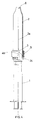
- the syringe (1) has two external annular groves (1a) having a semi-circular cross-section, one close to its tip and the other close to its opening.
- a cylindrical sliding cap (2) having an opening with a number of longitudinal slits which separate an annular series of elastic tabs (2a), each of which terminates with an internal raised edge (2b) having a semi-circular cross-section, which press fits, at the end of the backward or forward run of the cap (2) onto the syringe (1) into the above annular grooves (1a) which therefore act as end housings and end of run stops for the cap (2).
- the support collar (3) of the needle (3a) is made in a bell-shaped chamber (4) having an ogival shape, whose external surface fits perfectly with the cylindrical surface of the body of the syringe (1).
- the collar (3) can therefore be removed form the opening of the syringe (1) with the needle (3a) covered and enclosed inside the cap (2); in holding the cap by its opening, the connection with the bell-shaped chamber (4), is strengthened and stabilized, so that the same is fastened to the cap (2) and is removed from the syringe (1) together with the cap.
- the cap (2) is fitted with a nut (5) which is screwed outside its opening, thereby creating a gradual hold of the elastic tabs (2c), whose external profile is suitable slanted for this purpose in order to interfere with the opening of the nut (5).
- the elastic tabs do not have any raised internal edge, and the syringe (1) and the bell-shaped chamber (4b) does not have annular grooves for hooking the elastic tabs, since the cap (2) is not stopped by the male and female coupling of adjacent elements, but simply by adherence on the external surface of the syringe (1) or of the bell-shaped chamber (4b) of the tabs (2c) which are gradually fixed by the nut (5) as it is screwed.
- the cap (2) has a centre hole at its tip which allows the needle (3a) to move out when the cap in pushed back completely.
- this hole is closed by a spongy membrane (6) soaked with disinfecting and sterilizing substances which hermetically seals the internal compartment of the cap until such time as the syringe is used, but which can be easily crossed by the needle (3a) when it is pushed out, as soon as the cap (2) is pulled backwards.
- a small removable cap could be used which hermetically closes the hole on the tip of the sliding cap.
Landscapes
- Health & Medical Sciences (AREA)
- Engineering & Computer Science (AREA)
- Heart & Thoracic Surgery (AREA)
- Vascular Medicine (AREA)
- Anesthesiology (AREA)
- Biomedical Technology (AREA)
- Environmental & Geological Engineering (AREA)
- Hematology (AREA)
- Life Sciences & Earth Sciences (AREA)
- Animal Behavior & Ethology (AREA)
- General Health & Medical Sciences (AREA)
- Public Health (AREA)
- Veterinary Medicine (AREA)
- Infusion, Injection, And Reservoir Apparatuses (AREA)
Abstract
Description
- fig. 1 shows the syringe according to the invention, represented with a half view and a half cross-section, with the protection cap pulled out in full to cover the needle;
- fig. 2 shows the syringe according to the invention, represented with a half view and a half cross-section with the protection cap removed from the body of the syringe but still hooked to the support collar of the needle.
- fig. 3 shows the syringe according to the invention, represented in a half view and in a half cross-section, with the support collar of the needle removed from the syringe and hooked inside the protection cap.
- fig. 4 shows the syringe according to the invention in a further construction embodiment having a fixing nut to stop the sliding cap.
Claims (5)
- A single-use syringe having a protection cap (2) for the needle (3a) sliding longitudinally outside the syringe (1); the cap (2) and the syringe (1) being connected with a reciprocal coupling mechanism, whose interference creates the forward and backward end of run stop points of the cap (2) along the syringe (1) characterised in that a support collar (3) of the needle (3a) is housed inside a removable bell-shaped chamber (4) having an ogival shape, whose external surface connects precisely with the cylindrical shape of the body of the syringe (1) where the cap (2) is provided with a suitable connection mechanism inside the opening of the sliding cap for coupling the bell-shaped chamber (4).
- A single-use syringe according to claim 1 characterised in that the base of the bell-shaped chamber (4) is provided with an external annular groove (4a) having a semi-circular cross-section identical to two annular grooves (1a) close to the tip and the opening of the syringe (1); the sliding cap (2) being provided with a series of elastic tabs (2a) at its mouth which has a raised internal edge (2b) coupling with the annular grooves (1a) of the syringe (1) and with the annular grooves (4a) of the bell-shaped chamber.
- A single-use syringe having a protection cap (2) for the needle (3a) sliding longitudinally outside the syringe (1); the cap (2) and the syringe (1) being connected with a reciprocal coupling mechanism, whose interference creates the forward and backward end of run stop points of the cap (2) along the syringe (1) characterised in that a support collar (3) of the needle (3a) is housed inside a removable bell-shaped chamber (4) having an ogival shape, whose external surface connects precisely with the cylindrical shape of the body o the syringe (1) where:the bell-shaped chamber (4) has a section of the base with cylindrical profile;the cap (2) is provided, at its mouth, with a series of elastic tabs (2c) having a slanted external profile with which a nut (5) screwed externally to the mouth of the cap (2), interferes.
- A single-use syringe according to claims 1 and 3, characterised in that the cap (2) at its tip is provided with a hole sealed by a spongy membrane (6) soaked in sterilising or disinfecting substances.
- A single-use syringe according to claims 1 and 3, characterised in that the cap (2) at its tip has a hole sealed by a small removable cap.
Applications Claiming Priority (4)
| Application Number | Priority Date | Filing Date | Title |
|---|---|---|---|
| IT59290U | 1990-10-19 | ||
| IT59290U IT222316Z2 (en) | 1990-10-19 | 1990-10-19 | DISPOSABLE SYRINGE INCORPORATING A SLIDING HOOD FOR NEEDLE PROTECTION. |
| ITAN910010 | 1991-04-19 | ||
| ITAN910010A IT1249110B (en) | 1991-04-19 | 1991-04-19 | Improved disposable syringe fitted with a slidable protective cap which also serves to remove the needle |
Publications (2)
| Publication Number | Publication Date |
|---|---|
| EP0485345A1 EP0485345A1 (en) | 1992-05-13 |
| EP0485345B1 true EP0485345B1 (en) | 1998-03-04 |
Family
ID=26329614
Family Applications (1)
| Application Number | Title | Priority Date | Filing Date |
|---|---|---|---|
| EP91830430A Expired - Lifetime EP0485345B1 (en) | 1990-10-19 | 1991-10-14 | A single-use syringe incorporating a sliding protection cap for the needle |
Country Status (4)
| Country | Link |
|---|---|
| US (1) | US5154698A (en) |
| EP (1) | EP0485345B1 (en) |
| AT (1) | ATE163552T1 (en) |
| DE (1) | DE69129001T2 (en) |
Cited By (7)
| Publication number | Priority date | Publication date | Assignee | Title |
|---|---|---|---|---|
| US6254575B1 (en) | 1999-11-04 | 2001-07-03 | Specialized Health Products | Reaccessible medical needle safety devices and methods |
| US6280420B1 (en) | 1999-11-04 | 2001-08-28 | Specialized Health Products | Reaccessible medical needle safety devices and methods |
| US6592556B1 (en) | 2000-07-19 | 2003-07-15 | Tyco Healthcare Group Lp | Medical needle safety apparatus and methods |
| US7001363B2 (en) | 2002-04-05 | 2006-02-21 | F. Mark Ferguson | Safety shield for medical needles |
| US7862547B2 (en) | 1999-11-04 | 2011-01-04 | Tyco Healthcare Group Lp | Safety shield for medical needles |
| US8172809B2 (en) | 1999-11-04 | 2012-05-08 | Tyco Healthcare Group Lp | Safety shield apparatus and mounting structure for use with medical needle devices |
| US8496627B2 (en) | 2006-03-21 | 2013-07-30 | Covidien Lp | Passive latch ring safety shield for injection devices |
Families Citing this family (28)
| Publication number | Priority date | Publication date | Assignee | Title |
|---|---|---|---|---|
| WO1992021393A1 (en) * | 1991-05-26 | 1992-12-10 | Arturo Moises Gotthelf | Safety device for medical syringe |
| US5217436A (en) * | 1992-01-21 | 1993-06-08 | Farkas Paul J | Remote cannula removal cartridge syringe |
| FR2694198B1 (en) * | 1992-07-31 | 1994-10-21 | Claude Trapp | Injection needle protection device. |
| AR246435A1 (en) * | 1992-08-20 | 1994-08-31 | Moreno Saul | Disposable syringe for use with a needle sheath. |
| US5352208A (en) * | 1992-11-30 | 1994-10-04 | Robinson Wilbur D | Safe non-reusable hypodermic syringe |
| WO1996002290A1 (en) * | 1994-07-19 | 1996-02-01 | Novo Nordisk A/S | Needle magazine |
| US5658254A (en) * | 1995-03-31 | 1997-08-19 | Becton, Dickinson And Company | Syringe having safety needle shield |
| US5868245A (en) * | 1996-05-15 | 1999-02-09 | Intermedics, Inc. | Antiseptic disposables and methods for medical and surgical procedures |
| US5697908A (en) * | 1996-09-26 | 1997-12-16 | Becton Dickinson France, S.A. | Lockable safety shield for a prefillable syringe |
| SE511989C2 (en) * | 1997-09-22 | 2000-01-10 | Gudmar Olovson | needleguard |
| US6004296A (en) * | 1997-09-30 | 1999-12-21 | Becton Dickinson France, S.A. | Lockable safety shield assembly for a prefillable syringe |
| US5947933A (en) * | 1998-09-30 | 1999-09-07 | Becton, Dickinson And Company | Syringe having safety shield |
| US6235005B1 (en) * | 1998-12-28 | 2001-05-22 | Ethicon, Inc. | Positive engagement-disengagement catheter sleeve |
| US6632201B1 (en) | 1999-11-17 | 2003-10-14 | Baxter International Inc. | Locking needle protector |
| GB0003790D0 (en) | 2000-02-18 | 2000-04-05 | Astrazeneca Uk Ltd | Medical device |
| US6663602B2 (en) | 2000-06-16 | 2003-12-16 | Novo Nordisk A/S | Injection device |
| KR20020088246A (en) * | 2001-05-19 | 2002-11-27 | 신현달 | Cylinder,needle and cap unified safety syringe. |
| US7566327B2 (en) | 2002-08-09 | 2009-07-28 | Fenwal, Inc. | Needle protector |
| US11083841B2 (en) | 2002-08-09 | 2021-08-10 | Fenwal, Inc. | Needle protector, needle assembly and fluid processing set including the same |
| CA2584760C (en) | 2004-10-21 | 2013-12-24 | Novo Nordisk A/S | Dial-down mechanism for wind-up pen |
| ES2389866T3 (en) | 2006-05-18 | 2012-11-02 | Novo Nordisk A/S | Injection device with locking mode |
| US20090187150A1 (en) * | 2008-01-15 | 2009-07-23 | Domrex Pharma Inc. | Method and apparatus for covering a needle of a syringe |
| US9132239B2 (en) * | 2008-10-24 | 2015-09-15 | Novo Nordisk A/S | Dial-down mechanism for wind-up pen |
| GB2465390A (en) * | 2008-11-17 | 2010-05-19 | Owen Mumford Ltd | Syringe needle cover remover |
| GB2494453B (en) * | 2011-09-12 | 2013-08-07 | Owen Mumford Ltd | Injector assembly |
| US9533106B2 (en) | 2011-12-29 | 2017-01-03 | Novo Nordisk A/S | Torsion-spring based wind-up auto injector pen with dial-up/dial-down mechanism |
| TW201902526A (en) * | 2017-06-09 | 2019-01-16 | 云揚有限公司 | Protective sleeve for syringe |
| CN109200397A (en) * | 2017-07-03 | 2019-01-15 | 云扬有限公司 | Applied to the protection sleeve pipe on syringe |
Family Cites Families (8)
| Publication number | Priority date | Publication date | Assignee | Title |
|---|---|---|---|---|
| GB2080689B (en) * | 1980-07-29 | 1984-10-31 | Dent Hugh Robert | Sterilising fitments for injection devices |
| US4416663A (en) * | 1981-10-26 | 1983-11-22 | Steri-Pac, Inc. | Self-sterilizing hypodermic syringe |
| US4425120A (en) * | 1982-04-15 | 1984-01-10 | Sampson Norma A | Shielded hypodermic syringe |
| US4702738A (en) * | 1986-05-22 | 1987-10-27 | Spencer Treesa A | Disposable hypodermic syringe and needle combination having retractable, accident preventing sheath |
| US4923445A (en) * | 1988-03-01 | 1990-05-08 | Ryan Medical, Inc. | Safety needled medical devices |
| FR2633520B1 (en) * | 1988-06-30 | 1992-04-30 | Brunel Marc | SYRINGE OF THE TYPE COMPRISING A SINGLE USE INJECTION NEEDLE, PARTICULARLY FOR THE DENTAL FIELD |
| US4927417A (en) * | 1988-07-07 | 1990-05-22 | Schneider Medical Technologies, Inc. | Safety sleeve adapter |
| US4969877A (en) * | 1988-10-19 | 1990-11-13 | The Pascall Medical Corporation | Syringe |
-
1991
- 1991-10-14 AT AT91830430T patent/ATE163552T1/en not_active IP Right Cessation
- 1991-10-14 DE DE69129001T patent/DE69129001T2/en not_active Expired - Fee Related
- 1991-10-14 EP EP91830430A patent/EP0485345B1/en not_active Expired - Lifetime
- 1991-10-15 US US07/777,664 patent/US5154698A/en not_active Expired - Fee Related
Cited By (9)
| Publication number | Priority date | Publication date | Assignee | Title |
|---|---|---|---|---|
| US6254575B1 (en) | 1999-11-04 | 2001-07-03 | Specialized Health Products | Reaccessible medical needle safety devices and methods |
| US6280420B1 (en) | 1999-11-04 | 2001-08-28 | Specialized Health Products | Reaccessible medical needle safety devices and methods |
| US6796968B2 (en) | 1999-11-04 | 2004-09-28 | Tyco Healthcare Group Lp | Reaccessible medical needle safety devices and methods |
| US7862547B2 (en) | 1999-11-04 | 2011-01-04 | Tyco Healthcare Group Lp | Safety shield for medical needles |
| US8172809B2 (en) | 1999-11-04 | 2012-05-08 | Tyco Healthcare Group Lp | Safety shield apparatus and mounting structure for use with medical needle devices |
| US8226617B2 (en) | 1999-11-04 | 2012-07-24 | Tyco Healthcare Group Lp | Safety shield apparatus and mounting structure for use with medical needle devices |
| US6592556B1 (en) | 2000-07-19 | 2003-07-15 | Tyco Healthcare Group Lp | Medical needle safety apparatus and methods |
| US7001363B2 (en) | 2002-04-05 | 2006-02-21 | F. Mark Ferguson | Safety shield for medical needles |
| US8496627B2 (en) | 2006-03-21 | 2013-07-30 | Covidien Lp | Passive latch ring safety shield for injection devices |
Also Published As
| Publication number | Publication date |
|---|---|
| DE69129001T2 (en) | 1998-10-29 |
| ATE163552T1 (en) | 1998-03-15 |
| EP0485345A1 (en) | 1992-05-13 |
| US5154698A (en) | 1992-10-13 |
| DE69129001D1 (en) | 1998-04-09 |
Similar Documents
| Publication | Publication Date | Title |
|---|---|---|
| EP0485345B1 (en) | A single-use syringe incorporating a sliding protection cap for the needle | |
| US5454828A (en) | Lancet unit with safety sleeve | |
| US4846811A (en) | Sliding sheath for medical needles | |
| US5562625A (en) | Reusasble syringe with a disposable needle sheath | |
| US5207699A (en) | Lancet handling and disposal assembly | |
| US5246427A (en) | Safety hypodermic needle and shielding cap assembly | |
| JP4295821B2 (en) | Combination of safety needle assembly and medical device | |
| US4747831A (en) | Cannula insertion set with safety retracting needle | |
| EP0540217B1 (en) | Holder for double-ended needles | |
| US5047016A (en) | Fluid passing apparatus with means for covering the same | |
| EP0707860B1 (en) | Safety shield assembly for a needle | |
| US5718689A (en) | Free-standing safety cap for permanently storing contaminated medical instruments | |
| US4898589A (en) | Fluid passing apparatus with means for covering the same | |
| US5009642A (en) | Self-blunting needle assembly for use with a catheter, and catheter assembly using the same | |
| EP0321903A2 (en) | Fluid passing apparatus with means for covering the same | |
| US4986818A (en) | Syringe assembly | |
| US4915698A (en) | Device for removing and replacing needle cover on syringe | |
| US4964866A (en) | Needle sheath assembly | |
| US5156431A (en) | Needle cap clamp | |
| US5067490A (en) | Single use, safety blood collecting device | |
| US4846809A (en) | Needle tip protective device | |
| US5108379A (en) | Fluid passing apparatus with means for covering the same | |
| US4946447A (en) | Protective cover for hypodermic needle | |
| JPH02211126A (en) | Canula-protecting device for collecting blood | |
| WO2000048650A1 (en) | A disposable syringe with retractable needle |
Legal Events
| Date | Code | Title | Description |
|---|---|---|---|
| PUAI | Public reference made under article 153(3) epc to a published international application that has entered the european phase |
Free format text: ORIGINAL CODE: 0009012 |
|
| AK | Designated contracting states |
Kind code of ref document: A1 Designated state(s): AT BE CH DE DK ES FR GB GR LI LU NL SE |
|
| 17P | Request for examination filed |
Effective date: 19930203 |
|
| 17Q | First examination report despatched |
Effective date: 19950216 |
|
| GRAG | Despatch of communication of intention to grant |
Free format text: ORIGINAL CODE: EPIDOS AGRA |
|
| GRAG | Despatch of communication of intention to grant |
Free format text: ORIGINAL CODE: EPIDOS AGRA |
|
| GRAH | Despatch of communication of intention to grant a patent |
Free format text: ORIGINAL CODE: EPIDOS IGRA |
|
| GRAH | Despatch of communication of intention to grant a patent |
Free format text: ORIGINAL CODE: EPIDOS IGRA |
|
| GRAA | (expected) grant |
Free format text: ORIGINAL CODE: 0009210 |
|
| AK | Designated contracting states |
Kind code of ref document: B1 Designated state(s): AT BE CH DE DK ES FR GB GR LI LU NL SE |
|
| PG25 | Lapsed in a contracting state [announced via postgrant information from national office to epo] |
Ref country code: NL Free format text: LAPSE BECAUSE OF FAILURE TO SUBMIT A TRANSLATION OF THE DESCRIPTION OR TO PAY THE FEE WITHIN THE PRESCRIBED TIME-LIMIT Effective date: 19980304 Ref country code: LI Free format text: LAPSE BECAUSE OF FAILURE TO SUBMIT A TRANSLATION OF THE DESCRIPTION OR TO PAY THE FEE WITHIN THE PRESCRIBED TIME-LIMIT Effective date: 19980304 Ref country code: GR Free format text: LAPSE BECAUSE OF FAILURE TO SUBMIT A TRANSLATION OF THE DESCRIPTION OR TO PAY THE FEE WITHIN THE PRESCRIBED TIME-LIMIT Effective date: 19980304 Ref country code: ES Free format text: THE PATENT HAS BEEN ANNULLED BY A DECISION OF A NATIONAL AUTHORITY Effective date: 19980304 Ref country code: CH Free format text: LAPSE BECAUSE OF FAILURE TO SUBMIT A TRANSLATION OF THE DESCRIPTION OR TO PAY THE FEE WITHIN THE PRESCRIBED TIME-LIMIT Effective date: 19980304 Ref country code: BE Free format text: LAPSE BECAUSE OF FAILURE TO SUBMIT A TRANSLATION OF THE DESCRIPTION OR TO PAY THE FEE WITHIN THE PRESCRIBED TIME-LIMIT Effective date: 19980304 Ref country code: AT Free format text: LAPSE BECAUSE OF FAILURE TO SUBMIT A TRANSLATION OF THE DESCRIPTION OR TO PAY THE FEE WITHIN THE PRESCRIBED TIME-LIMIT Effective date: 19980304 |
|
| REF | Corresponds to: |
Ref document number: 163552 Country of ref document: AT Date of ref document: 19980315 Kind code of ref document: T |
|
| REG | Reference to a national code |
Ref country code: CH Ref legal event code: EP |
|
| REF | Corresponds to: |
Ref document number: 69129001 Country of ref document: DE Date of ref document: 19980409 |
|
| PG25 | Lapsed in a contracting state [announced via postgrant information from national office to epo] |
Ref country code: SE Free format text: LAPSE BECAUSE OF FAILURE TO SUBMIT A TRANSLATION OF THE DESCRIPTION OR TO PAY THE FEE WITHIN THE PRESCRIBED TIME-LIMIT Effective date: 19980604 Ref country code: DK Free format text: LAPSE BECAUSE OF FAILURE TO SUBMIT A TRANSLATION OF THE DESCRIPTION OR TO PAY THE FEE WITHIN THE PRESCRIBED TIME-LIMIT Effective date: 19980604 |
|
| ET | Fr: translation filed | ||
| NLV1 | Nl: lapsed or annulled due to failure to fulfill the requirements of art. 29p and 29m of the patents act | ||
| REG | Reference to a national code |
Ref country code: CH Ref legal event code: PL |
|
| PG25 | Lapsed in a contracting state [announced via postgrant information from national office to epo] |
Ref country code: LU Free format text: LAPSE BECAUSE OF NON-PAYMENT OF DUE FEES Effective date: 19981014 |
|
| PLBE | No opposition filed within time limit |
Free format text: ORIGINAL CODE: 0009261 |
|
| STAA | Information on the status of an ep patent application or granted ep patent |
Free format text: STATUS: NO OPPOSITION FILED WITHIN TIME LIMIT |
|
| 26N | No opposition filed | ||
| PGFP | Annual fee paid to national office [announced via postgrant information from national office to epo] |
Ref country code: GB Payment date: 19990401 Year of fee payment: 8 |
|
| PGFP | Annual fee paid to national office [announced via postgrant information from national office to epo] |
Ref country code: FR Payment date: 19990419 Year of fee payment: 8 |
|
| PGFP | Annual fee paid to national office [announced via postgrant information from national office to epo] |
Ref country code: DE Payment date: 19990427 Year of fee payment: 8 |
|
| PG25 | Lapsed in a contracting state [announced via postgrant information from national office to epo] |
Ref country code: GB Free format text: LAPSE BECAUSE OF NON-PAYMENT OF DUE FEES Effective date: 19991014 |
|
| GBPC | Gb: european patent ceased through non-payment of renewal fee |
Effective date: 19991014 |
|
| PG25 | Lapsed in a contracting state [announced via postgrant information from national office to epo] |
Ref country code: FR Free format text: LAPSE BECAUSE OF NON-PAYMENT OF DUE FEES Effective date: 20000630 |
|
| PG25 | Lapsed in a contracting state [announced via postgrant information from national office to epo] |
Ref country code: DE Free format text: LAPSE BECAUSE OF NON-PAYMENT OF DUE FEES Effective date: 20000801 |
|
| REG | Reference to a national code |
Ref country code: FR Ref legal event code: ST |