EP0487952A1 - Bauelement - Google Patents
Bauelement Download PDFInfo
- Publication number
- EP0487952A1 EP0487952A1 EP19910118967 EP91118967A EP0487952A1 EP 0487952 A1 EP0487952 A1 EP 0487952A1 EP 19910118967 EP19910118967 EP 19910118967 EP 91118967 A EP91118967 A EP 91118967A EP 0487952 A1 EP0487952 A1 EP 0487952A1
- Authority
- EP
- European Patent Office
- Prior art keywords
- component according
- mat
- outer shell
- area
- proportion
- Prior art date
- Legal status (The legal status is an assumption and is not a legal conclusion. Google has not performed a legal analysis and makes no representation as to the accuracy of the status listed.)
- Granted
Links
Images


Classifications
-
- E—FIXED CONSTRUCTIONS
- E04—BUILDING
- E04G—SCAFFOLDING; FORMS; SHUTTERING; BUILDING IMPLEMENTS OR AIDS, OR THEIR USE; HANDLING BUILDING MATERIALS ON THE SITE; REPAIRING, BREAKING-UP OR OTHER WORK ON EXISTING BUILDINGS
- E04G9/00—Forming or shuttering elements for general use
- E04G9/02—Forming boards or similar elements
-
- E—FIXED CONSTRUCTIONS
- E04—BUILDING
- E04C—STRUCTURAL ELEMENTS; BUILDING MATERIALS
- E04C2/00—Building elements of relatively thin form for the construction of parts of buildings, e.g. sheet materials, slabs, or panels
- E04C2/02—Building elements of relatively thin form for the construction of parts of buildings, e.g. sheet materials, slabs, or panels characterised by specified materials
- E04C2/10—Building elements of relatively thin form for the construction of parts of buildings, e.g. sheet materials, slabs, or panels characterised by specified materials of wood, fibres, chips, vegetable stems, or the like; of plastics; of foamed products
- E04C2/20—Building elements of relatively thin form for the construction of parts of buildings, e.g. sheet materials, slabs, or panels characterised by specified materials of wood, fibres, chips, vegetable stems, or the like; of plastics; of foamed products of plastics
- E04C2/205—Building elements of relatively thin form for the construction of parts of buildings, e.g. sheet materials, slabs, or panels characterised by specified materials of wood, fibres, chips, vegetable stems, or the like; of plastics; of foamed products of plastics of foamed plastics, or of plastics and foamed plastics, optionally reinforced
-
- E—FIXED CONSTRUCTIONS
- E04—BUILDING
- E04G—SCAFFOLDING; FORMS; SHUTTERING; BUILDING IMPLEMENTS OR AIDS, OR THEIR USE; HANDLING BUILDING MATERIALS ON THE SITE; REPAIRING, BREAKING-UP OR OTHER WORK ON EXISTING BUILDINGS
- E04G9/00—Forming or shuttering elements for general use
- E04G9/02—Forming boards or similar elements
- E04G9/05—Forming boards or similar elements the form surface being of plastics
-
- Y—GENERAL TAGGING OF NEW TECHNOLOGICAL DEVELOPMENTS; GENERAL TAGGING OF CROSS-SECTIONAL TECHNOLOGIES SPANNING OVER SEVERAL SECTIONS OF THE IPC; TECHNICAL SUBJECTS COVERED BY FORMER USPC CROSS-REFERENCE ART COLLECTIONS [XRACs] AND DIGESTS
- Y10—TECHNICAL SUBJECTS COVERED BY FORMER USPC
- Y10T—TECHNICAL SUBJECTS COVERED BY FORMER US CLASSIFICATION
- Y10T428/00—Stock material or miscellaneous articles
- Y10T428/249921—Web or sheet containing structurally defined element or component
- Y10T428/249953—Composite having voids in a component [e.g., porous, cellular, etc.]
- Y10T428/249976—Voids specified as closed
-
- Y—GENERAL TAGGING OF NEW TECHNOLOGICAL DEVELOPMENTS; GENERAL TAGGING OF CROSS-SECTIONAL TECHNOLOGIES SPANNING OVER SEVERAL SECTIONS OF THE IPC; TECHNICAL SUBJECTS COVERED BY FORMER USPC CROSS-REFERENCE ART COLLECTIONS [XRACs] AND DIGESTS
- Y10—TECHNICAL SUBJECTS COVERED BY FORMER USPC
- Y10T—TECHNICAL SUBJECTS COVERED BY FORMER US CLASSIFICATION
- Y10T428/00—Stock material or miscellaneous articles
- Y10T428/249921—Web or sheet containing structurally defined element or component
- Y10T428/249953—Composite having voids in a component [e.g., porous, cellular, etc.]
- Y10T428/249986—Void-containing component contains also a solid fiber or solid particle
-
- Y—GENERAL TAGGING OF NEW TECHNOLOGICAL DEVELOPMENTS; GENERAL TAGGING OF CROSS-SECTIONAL TECHNOLOGIES SPANNING OVER SEVERAL SECTIONS OF THE IPC; TECHNICAL SUBJECTS COVERED BY FORMER USPC CROSS-REFERENCE ART COLLECTIONS [XRACs] AND DIGESTS
- Y10—TECHNICAL SUBJECTS COVERED BY FORMER USPC
- Y10T—TECHNICAL SUBJECTS COVERED BY FORMER US CLASSIFICATION
- Y10T428/00—Stock material or miscellaneous articles
- Y10T428/249921—Web or sheet containing structurally defined element or component
- Y10T428/249953—Composite having voids in a component [e.g., porous, cellular, etc.]
- Y10T428/249987—With nonvoid component of specified composition
- Y10T428/249991—Synthetic resin or natural rubbers
-
- Y—GENERAL TAGGING OF NEW TECHNOLOGICAL DEVELOPMENTS; GENERAL TAGGING OF CROSS-SECTIONAL TECHNOLOGIES SPANNING OVER SEVERAL SECTIONS OF THE IPC; TECHNICAL SUBJECTS COVERED BY FORMER USPC CROSS-REFERENCE ART COLLECTIONS [XRACs] AND DIGESTS
- Y10—TECHNICAL SUBJECTS COVERED BY FORMER USPC
- Y10T—TECHNICAL SUBJECTS COVERED BY FORMER US CLASSIFICATION
- Y10T428/00—Stock material or miscellaneous articles
- Y10T428/25—Web or sheet containing structurally defined element or component and including a second component containing structurally defined particles
- Y10T428/256—Heavy metal or aluminum or compound thereof
-
- Y—GENERAL TAGGING OF NEW TECHNOLOGICAL DEVELOPMENTS; GENERAL TAGGING OF CROSS-SECTIONAL TECHNOLOGIES SPANNING OVER SEVERAL SECTIONS OF THE IPC; TECHNICAL SUBJECTS COVERED BY FORMER USPC CROSS-REFERENCE ART COLLECTIONS [XRACs] AND DIGESTS
- Y10—TECHNICAL SUBJECTS COVERED BY FORMER USPC
- Y10T—TECHNICAL SUBJECTS COVERED BY FORMER US CLASSIFICATION
- Y10T442/00—Fabric [woven, knitted, or nonwoven textile or cloth, etc.]
- Y10T442/30—Woven fabric [i.e., woven strand or strip material]
- Y10T442/3325—Including a foamed layer or component
- Y10T442/3333—Including a free metal or alloy constituent
Definitions
- the invention relates to a component according to German patent application P39 16 938.3. Wood itself is becoming increasingly rare and types of wood with the same properties are becoming even rarer. In contrast, oil seems to be far more available than previously thought. Recent discoveries in Saudi Arabia have made oil production seem secure at least until the century after next. This means that plastic is available. The problems of what to do with used plastic are already very pressing. The so-called recycling poses great problems, since nobody can think of a right way to recycle the used plastic in large quantities.
- the object of the invention is to further improve the components after the main application. Particular attention was paid to stiffness, nailability, creep behavior, thermal conductivity and temperature resistance.
- the component has the shape of a formwork panel 11, which can be used for concrete formwork. It has two outer shell regions 12, 13. These have outer surfaces 14, 16, to which surface regions 17, 18 adjoin, which make up part of the thickness of the outer shell regions 12, 13. Between 12, 13 there is an inner region 19 which has foam 21. There are mats 22, 23 in the outer shell regions 12, 13. These, like 12, 13, 14, 16, 17, 18, 19, 21, extend parallel to a geometric center plane 24.
- the diameter of the foam bubbles differs from the solid surface areas 17, 18 to the geometric center plane 24. This is shown in Fig. 2. Um around the geometric center plane 24, the diameter D of the bubbles is largest, then drops to the beginning of 12, 13 and in 12, 13 the diameter is zero, which means that the outer shell regions 12, 13 are solid.
- the foam area still extends into the outer shell areas 12, 13, but with bubbles that go back to zero diameter.
- the mats 22, 23 are located, however, the bubble diameter has previously dropped to zero.
- the mats 22, 23 are therefore, as in the exemplary embodiment according to FIG. 2, in solid material.
- metal threads 26 and metal threads 27 form the mat 22.
- the mat 23 looks exactly the same and is therefore not described.
- the metal threads 26, 27 are made of steel and 0.16 mm thick.
- the metal threads 26 run in the X direction and the metal threads 27 in the Y direction, that is to say they are perpendicular to one another.
- the mesh size 28 is the same in both directions, namely 7x7 mm. It is ensured in a manner not shown that the crossing points 29 remain undamaged.
- the mat 22 is made easier to handle by an auxiliary scaffold 31 which is connected to the metal threads 26, 27 in a manner not shown.
- the auxiliary scaffold 31 consists of threads of considerably lower tensile force and either does not determine the properties of the formwork panel plate 11 or only to a very small extent.
- FIG. 5 shows a cut mold half 32 at the top and a complementary mold half 33 at the bottom. These can be pressed together under pressure and temperature. Compressed in it is 12, 22 on the one hand, 13, 23 on the other hand, which have already been produced in another way and between the two 19. A formwork panel 11 is then produced according to FIG. 2, provided that the initial height of 12, 13, 19 is initially greater is as the clear height with closed mold halves 32, 33. Then 12, 13 press a little into 19, but do not become foamy themselves.
- a hopper 34 with a slot die 36 is provided for a second method. This is followed by two pair of calender rollers 37, 38.
- the hopper is fed with material 42, 43, 44 and the supplied mats 22, 23.
- the materials 42 and 44 are each processed via an extruder 45a, b, each of which contains a degassing zone 39.
- the material 43 is passed through an extruder 45c which has a degassing zone 39 and then a gas feed zone 41.
- the plastic material 42, 43, 44 is enriched with metal tape bodies according to the main application P39 16 938.3. Also with chopped glass fibers.
- Between 42 and 43 a mat 22, 23 is fed down from supply rolls 46, 47, respectively. 42, 43, 44 are brought together in funnel 34.
- gas that is generated unintentionally and / or accidentally is drawn off.
- Gas is added to the gas supply zone 41 in a controlled manner into the material 43, which later forms the inner region 19.
- the supply of the plastic material 42, 43 is to be understood as drawn symbolically. Of course, no plates are fed.
- the pair of rollers 37, 38 smooth the outer surfaces 14, 16 on the product as long as it has not yet cooled.
- the invention is capable of numerous variations. Only if you want to have symmetrical properties, you build the formwork panel 11 symmetrical to the geometric center plane 24. If one omits one of the mats 22, 23, the product receives a one-sided pretension, which is desirable for some applications. If desired, the outer surfaces 14, 16 can also be structured. In certain applications, both mats 22, 23 can be present. The one can then lie a little further inside and the other a little further outside and / or the metal threads can have different properties, which likewise lead to a desired symmetry can.
- the metal threads 26, 27 can be located in a plastic jacket which is welded at the intersection points 29, so that the auxiliary scaffold 31 is unnecessary. The plastic jacket then melts in the supplied plastic.
- the mat 23 can be knitted or woven. It can also be a sheet from which a large number of parts are punched out, so that only webs remain. Such sheets sometimes occur when small parts are punched out.
- the component can be lighter than wood, but have better mechanical properties.
- the surface can be regenerated in a simple manner, e.g. use a glowing wire as a smoothing tool or hot iron the surface.
- the inner region 19, apart from the plastic component, has only a very low proportion of metal strip bodies and glass fibers. It is less than 10% in each case. In the embodiment in the range of 5% aluminum chips and 5% glass fibers.
- the nailability is directly dependent on the proportion of polyamide, depending on the proportion of HDPE and LDPE. Nailability ceases at around 18% PA. Additions of LDPE make the component more nail-friendly. However, the thrust absorption and creep resistance then decrease. If HDPE and LDPE are added in the same ratio, the polyamide content can be increased to 30%, where the nailability ends.
- the degree of filling of the reinforcement materials, So the metal strip bodies and the glass fibers, the nail ability is not impaired as long as the individual proportion is below 22%. In addition, the material becomes too dense.
- the creep behavior depends on the concentration of the reinforcement materials and their length in the end product, provided that their adhesion and integration is guaranteed. It seems that shavings or the like with a length of 12 to 13 mm bring the greatest effect and let the formwork plate 11 appear as a spring which immediately returns to its original position after relief and very quickly approaches a final deformation under permanent load.
- the thermal conductivity greatly influences the pressing time and the setting behavior of the concrete. Only the concentration of metal strip bodies determines the thermal conductivity. With a share of 15% aluminum chips, you have values of a comparable wooden panel. The good thermal conductivity results in a fairly uniform cooling of the component, so that no voltages are implanted. This guarantees a distortion-free shape when cooled.
- the outer shell areas 12, 13 are filled to a high level, for example with 20% aluminum chips, 20% glass fibers, 20% PA and 20% HDPE and LDPE in each case. It should be possible to use less glass fiber and aluminum chips due to the dimensions of the mats 22, 23.
- the inner area 19 is only slightly filled, e.g. up to 5% aluminum shavings and glass fibers.
- the foamed zone results in a considerable weight reduction, e.g. of 60%.
- a method according to FIG. 5 is not as economical as a method according to FIG. 6. However, production can be achieved more quickly. The reverse applies to a method according to FIG. 6.
- a minimum distance of 7 ⁇ 7 mm was mentioned in the exemplary embodiment for the mesh size 28 in both directions. Depending on the static requirements, this can be larger or smaller and also different in one direction in relation to others.
- the mats can also consist of expanded rib metal.
- mixed forms are also possible, such as expanded rib metal and / or sheets from which parts have been punched out and / or knitted and / or woven and / or knitted mats.
- the layers such as mats, foams, outer shells, etc. are essentially parallel to one another and the mats are essentially flat.
Abstract
Description
- Die Erfindung betrifft ein Bauelement nach der deutschen Patentanmeldung P39 16 938.3. Holz an sich wird immer seltener und Holzsorten gleicher Eigenschaften werden noch seltener. Dagegen scheint Erdöl weit mehr verfügbar zu sein als bisher angenommen. Neuere Funde in Saudi-Arabien lassen die Erdölförderung mindestens bis in das übernächste Jahrhundert gesichert erscheinen. Dies bedeutet, daß Kunststoff verfügbar ist. Jetzt schon sehr drückend sind die Probleme, was mit gebrauchtem Kunststoff geschehen soll. Das sogenannte Recycling bereitet große Probleme, da niemandem ein rechter Weg einfällt, den gebrauchten Kunststoff in großen Mengen der Wiederverwertung zuzuführen.
- Aufgabe der Erfindung ist es, die Bauelemente nach der Hauptanmeldung weiterzuverbessern. Besonderes Augenmerk wurde gelegt auf die Steifigkeit, die Nagelbarkeit, das Kriechverhalten, die Wärmeleitfähigkeit und die Temperaturbeständigkeit.
- Erfindungsgemäß wird diese Aufgabe durch die aus dem kennzeichnenden Teil des Hauptanspruchs ersichtlichen Merkmale gelöst.
- Bevorzugte Ausführungsbeispiele sind der Zeichnung zu entnehmen. In der Zeichnung zeigen schematisch:
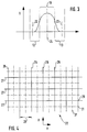
- Fig. 1
- Einen abgebrochenen Querschnitt durch eine Platte, wie sie z.B. als Schalplatte verwendet werden kann,
- Fig. 2
- zeigt ein Diagramm über die statistische Verteilung von Schaumporen-Durchmessern beiderseits der geometrischen Mittenebene für ein erstes Ausführungsbeispiel,
- Fig. 3
- eine Darstellung wie Fig. 2, jedoch für ein zweites Ausführungsbeispiel,
- Fig. 4
- die Draufsicht auf eine Matte aus Metallfäden,
- Fig. 5
- einen Querschnitt durch eine Preßform mit einzulegenden Schichten im explodierten Zustand,
- Fig. 6
- die Darstellung eines Extrusionsverfahrens.
- Gemäß Fig. 1 hat das Bauelement die Gestalt einer Schaltafelplatte 11, die für Betonschalungen verwendbar ist. Sie hat zwei Außenschalenbereiche 12, 13. Diese haben Außenflächen 14, 16, an die sich Oberflächenbereiche 17, 18 anschließen, die einen Teil der Dicke der Außenschalenbereiche 12, 13 ausmachen. Zwischen 12, 13 befindet sich ein Innenbereich 19, der Schaumstoff 21 aufweist. In den Außenschalenbereichen 12, 13 befinden sich Matten 22, 23. Diese, wie auch 12, 13, 14, 16, 17, 18, 19, 21 erstrecken sich parallel zu einer geometrischen Mittenebene 24.
- Je nach Herstellungsverfahren ist der Durchmesser der Schaumblasen, aus denen der Schaumstoff 21 zu seinem größten Teil besteht, von den massiven Oberflächenbereichen 17, 18 bis zur geometrischen Mittenebene 24 unterschiedlich. Dies zeigt Fig. 2. Um die geometrische Mittenebene 24 herum ist der Durchmesser D der Blasen am größten, fällt dann bis zum Beginn von 12, 13 ab und in 12, 13 ist der Durchmesser Null, das heißt, daß die Außenschalenbereiche 12, 13 massiv sind.
- Bei einem anderen Herstellungsverfahren gemäß Fig. 3 reicht der Schaumbereich noch in die Außenschalenbereiche 12, 13 hinein, jedoch mit auf den Durchmesser Null zurückgehenden Blasen. Dort wo sich die Matten 22, 23 befinden, ist jedoch der Blasendurchmesser schon vorher auf Null abgesunken. Die Matten 22, 23 befinden sich daher wie beim Ausführungsbeispiel nach Fig. 2 in massivem Material.
- Gemäß Fig. 4 bilden Metallfäden 26 und Metallfäden 27 die Matte 22. Die Matte 23 sieht exakt gleich aus und wird deshalb nicht beschrieben. Die Metallfäden 26, 27 sind aus Stahl und 0,16 mm dick. Die Metallfäden 26 verlaufen in der X- und die Metallfäden 27 in der Y-Richtung, stehen also senkrecht aufeinander. Die Maschenweite 28 ist in beiden Richtungen gleich groß, nämlich 7x7 mm. Auf nicht dargestellte Weise ist sichergestellt, daß die Kreuzungspunkte 29 unverrückt bleiben. Für den Fall, daß die Metallfäden 26, 27 sich wegen ihrer Offenheit nicht verarbeiten lassen, ist die Matte 22 durch ein Hilfsgerüst 31 besser handhabbar gemacht, das auf nicht dargestellte Weise mit den Metallfäden 26, 27 verbunden ist. Das Hilfsgerüst 31 besteht aus Fäden ganz erheblich niedrigerer Zugkraft und bestimmt die Eigenschaften der Schaltafelplatte 11 entweder nicht oder nur in sehr kleinem Ausmaß.
- Fig. 5 zeigt oben eine geschnittene Formhälfte 32 und unten eine komplimentäre Formhälfte 33. Diese kann man unter Druck und Temperatur zusammenpressen. Zusammengepreßt in ihr wird 12, 22 einerseits, 13, 23 andererseits, die schon anderweitig fertig hergestellt sind und zwischen beiden 19. Es entsteht dann eine Schaltafelplatte 11 gemäß Fig. 2, sofern die Ausgangshöhe von 12, 13, 19 zunächst größer ist als die lichte Höhe bei geschlossenen Formhälften 32, 33. Es drücken sich dann 12, 13 ein wenig in 19 hinein, werden selbst aber nicht schaumig.
- Gemäß Fig. 6 hat man für ein zweites Verfahren einen Trichter 34, mit Breitschlitzdüse 36. Dieser nachgeschaltet sind zwei Kalander-Paarwalzen 37, 38. Der Trichter wird mit Material 42, 43, 44 sowie den zugeführten Matten 22, 23 beschickt. Die Materialien 42 und 44 werden über je einen Extruder 45a, b aufgearbeitet, der jeweils eine Entgasungszone 39 enthält. Das Material 43 wird über einen Extruder 45c geführt, der eine Entgasungszone 39 und danach eine Gaszufuhrzone 41 hat. Das Kunststoffmaterial 42, 43, 44 ist gemäß der Hauptanmeldung P39 16 938.3 mit Metall-Bandkörpern angereichert. Ferner zusätzlich mit gechoppten Glasfasern. Zwischen 42 und 43 wird von Vorratsrollen 46, 47 herunter jeweils eine Matte 22, 23 zugeführt. Im Trichter 34 werden 42, 43, 44 zusammengeführt. In der Entgasungszone 39 wird etwa unbeabsichtigt und/oder zufällig entstandenes Gas abgezogen. In das Material 43, welches später den Innenbereich 19 bildet, wird der Gaszufuhrzone 41 kontrolliert Gas zugegeben. Man hat damit einen Blasendurchmesserverlauf z.B. von Fig. 4 im Griff. Die Zufuhr des Kunststoffmaterials 42, 43 ist als symbolisch gezeichnet zu verstehen. Es werden natürlich keine Platten zugeführt. Die Paarwalzen 37, 38 glätten die Außenflächen 14, 16 am Produkt, so lange es sich noch nicht abgekühlt hat.
- Wie schon die Ansprüche erkennen lassen, ist die Erfindung zahlreicher Variationen fähig. Nur wenn man symmetrische Eigenschaften haben will, baut man die Schaltafelplatte 11 symmetrisch zur geometrischen Mittenebene 24 auf. Läßt man eine der Matten 22, 23 weg, dann erhält das Produkt eine einseitige Vorspannung, was für manche Anwendungszwecke erwünscht ist. Die Außenflächen 14, 16 können erwünschtenfalls auch strukturiert sein. In bestimmten Anwendungsfällen können beide Matten 22, 23 vorhanden sein. Dabei kann dann die eine etwas weiter innen und die andere etwas weiter außen liegen und/oder können die Metallfäden unterschiedliche Eigenschaften haben, was ebenfalls zu einer erwünschten Symmetrie führen kann. Die Metallfäden 26, 27 können sich in einem Kunststoffmantel befinden, der an den Kreuzungspunkten 29 verschweißt ist, so daß das Hilfsgerüst 31 überflüssig wird. Der Kunststoffmantel zerschmilzt dann im zugeführten Kunststoff. Die Matte 23 kann gestrickt oder gewoben sein. Sie kann auch ein Blech sein, aus dem sehr viele Teile herausgestanzt sind, so daß nur noch Stege übrigbleiben. Solche Bleche fallen manchmal beim Ausstanzen von Kleinteilen an.
- Weiß man, daß man das Bauelement nicht von beiden Seiten her benutzen wird (Schaltafelplatten werden gewendet), dann kann dementsprechend auch der Aufbau des Sandwich abgewandelt werden.
- Gewünschtenfalls kann das Bauelement leichter als Holz sein, jedoch bessere mechanische Eigenschaften haben.
- Wenn bei der Schaltafelplatte 11 eine der Außenflächen 14, 16 abgenutzt ist, dann kann man die Oberfläche auf einfache Weise regenerieren, indem man z.B. einen glühenden Draht als Glättungsinstrument verwendet oder die Oberfläche heiß bügelt.
- Infolge der Schaumstruktur hat der Innenbereich 19 abgesehen vom Kunststoffanteil nur einen sehr niedrigen Anteil an Metall-Bandkörpern und Glasfasern. Er beträgt jeweils unter 10 %. Beim Ausführungsbeispiel im Bereich von 5 % Aluminiumspänen und 5 % Glasfasern. Die Nagelbarkeit ist direkt abhängig vom Polyamidanteil in Abhängigkeit vom Anteil HDPE und LDPE. Bei etwa 18 % PA hört die Nagelbarkeit auf. Zumischungen von LDPE machen das Bauelement nagelfreundlicher. Es vermindert sich jedoch dann die Schubaufnahme und der Kriechwiderstand. Werden HDPE und LDPE im gleichen Verhältnis zugegeben, dann kann der Polyamidanteil auf 30 % gesteigert werden, wobei hier die Nagelfähigkeit endet. Vom Füllgrad der Bewehrungsstoffe, also den Metall-Bandkörpern und den Glasfasern, ist die Nagelfähigkeit nicht beeinträchtigt, solange der Einzelanteil unter 22 % liegt. Darüber hinaus wird das Material zu dicht.
- Das Kriechverhalten ist von der Konzentration der Bewehrungsstoffe und deren Länge im Endprodukt abhängig, sofern deren Haftung und Einbindung gewährleistet ist. Es scheint, daß Späne oder dergleichen mit einer Länge von 12 bis 13 mm die höchste Wirkung bringen und lassen die Schaltafelplatte 11 als Feder erscheinen, die nach Entlastung sofort in ihre Ursprungslage zurückgeht und unter Dauerbelastung sich sehr schnell einer Endverformung nähert.
- Die Wärmeleitfähigkeit beeinflußt in starkem Maß die Preßzeit und das Abbindeverhalten des Betons. Ausschließlich die Konzentration von Metall-Bandkörpern bestimmt die Wärmeleitfähigkeit. Bei einem Anteil von 15 % Aluspänen hat man Werte einer vergleichbaren Holzplatte. Durch die gute Wärmeleitfähigkeit entsteht eine ziemlich gleichmäßige Abkühlung des Bauelements, so daß keine Spannungen implantiert werden. Dies garantiert in ausgekühltem Zustand eine verzugsfreie Gestalt.
- Je höher der Polyamidanteil ist, umso größer ist der Widerstand gegen Temperatur. Diese Eigenschaft von Polyamid vermindert jedoch ab einem gewissen Prozentsatz die Nagelbarkeit. Versuche an Prototypen ergaben, daß ein Bereich von 12 bis 25 %, je nach Mischungsverhältnis, von PE, beide Faktoren optimieren, so daß eine relativ hohe Temperaturbeständigkeit erreicht wird und das Bauelement trotzdem nagelbar ist.
- Die Außenschalenbereiche 12, 13 sind hoch gefüllt, z.B. mit 20 % Aluspänen, 20 % Glasfasern, 20 % PA und jeweils 20 % HDPE und LDPE. Es dürfte möglich sein, durch die Dimensionierung der Matten 22, 23 weniger Glasfaser und Aluminiumspäne zu verwenden.
- Der Innenbereich 19 ist nur schwach gefüllt, z.B. bis zu 5 % Aluminiumspäne und Glasfasern. Durch die geschäumte Zone ergibt sich eine erhebliche Gewichtsverminderung, z.B. von 60 %.
- Ein Verfahren gemäß Fig. 5 ist zwar nicht so wirtschaftlich wie ein Verfahren gemäß Fig. 6. Man kommt jedoch schneller zu einer Produktion. Das Umgekehrte gilt für ein Verfahren gemäß Fig. 6.
- Zwar wurde beim Ausführungsbeispiel für die Maschenweite 28 in beiden Richtungen ein Mindestabstand von 7x7 mm erwähnt. Je nach statischen Erfordernissen kann dieser größer oder auch kleiner sein und außerdem in einer Richtung im Verhältnis zu anderen unterschiedlich.
- Die Matten können auch aus Rippenstreckmetall bestehen. Dabei sind grundsätzlich auch Mischformen möglich wie Rippenstreckmetall und/oder Bahnen, aus denen Teile ausgestanzt wurden und/oder gestrickte und/oder gewobene und/oder gewirkte Matten.
- Die Schichten wie Matten, Schaumstoffe, Außenschalen usw. liegen im wesentlichen parallel zueinander und die Matten sind im wesentlichen eben.
Claims (52)
- Bauelement nach deutscher Patentanmeldung P 39 16 938.3, gekennzeichnet durch einen Sandwichaufbau mit jeweils zwei Außenschalenbereichen, die zumindest in deren Oberflächenbereich massiv sind, mit einem Innenbereich, der mit den Außenschalenbereichen fest verbunden ist und mit einer Matte aus Metallfäden, die in einem der Außenschalenbereiche eingebettet ist und im wesentlichen parallel zum Oberflächenbereich verläuft.
- Bauelement nach Anspruch 1, dadurch gekennzeichnet, daß die Matte quer zu ihren beiden Ausdehnungen Durchbrechungen hat, die mindestens so groß sind, daß das Kunststoffmaterial sie durchdringt.
- Bauelement nach Anspruch 1, dadurch gekennzeichnet, daß das Kunststoffmaterial sie vollständig durchdringt und alle Flächen der Matte vollständig benetzt.
- Bauelement nach Anspruch 1, dadurch gekennzeichnet, daß der Gewichts-Anteil der Metall-Bandkörper in der Schaumstoffschicht ganz wesentlich geringer ist, als im Außenschalenbereich.
- Bauelement nach Anspruch 4, dadurch gekennzeichnet, daß der Gewichts-Anteil zwischen 0 und 25 % ist.
- Bauelement nach Anspruch 5, dadurch gekennzeichnet, daß der Gewichts-Anteil zwischen 0 und 20 % ist.
- Bauelement nach Anspruch 4, dadurch gekennzeichnet, daß der Gewichts-Anteil zwischen 0 und 15 % ist.
- Bauelement nach Anspruch 4, dadurch gekennzeichnet, daß der Gewichts-Anteil zwischen 0 und 10 % ist.
- Bauelement nach Anspruch 4, dadurch gekennzeichnet, daß der Gewichts-Anteil 5 % mit einer Schwankungsbreite von + 150 % - 100 % ist.
- Bauelement nach Anspruch 1, dadurch gekennzeichnet, daß die Außenschalenbereiche in ihrer Dicke addiert dünner als die Schaumstoffschicht sind.
- Bauelement nach Anspruch 10, dadurch gekennzeichnet, daß die Dicken sich wie 4:15:4 mit einer Schwankungsbreite von etwa ± 100 % verhalten.
- Bauelement nach Anspruch 1, dadurch gekennzeichnet, daß die Außenschalenbereiche etwa gleich dick sind.
- Bauelement nach Anspruch 12, dadurch gekennzeichnet, daß die Außenschalenbereiche genau gleich dick sind.
- Bauelement nach Anspruch 1, dadurch gekennzeichnet, daß die Porengröße der Schaumstoffschicht von deren Mittenebene nach außen abnimmt.
- Bauelement nach Anspruch 14, dadurch gekennzeichnet, daß die Abnahme stetig ist.
- Bauelement nach Anspruch 14, dadurch gekennzeichnet, daß auch der Außenschalenbereich in seinem inneren Bereich noch kleine Poren aufweist.
- Bauelement nach Anspruch 1 und 16, dadurch gekennzeichnet, daß die Matte im porenfreien Bereich liegt.
- Bauelement nach Anspruch 1, dadurch gekennzeichnet, daß nur im einen Außenschalenbereich eine Matte vorgesehen ist.
- Bauelement nach Anspruch 1, dadurch gekennzeichnet, daß in beiden Außenschalenbereichen je eine Matte vorgesehen ist.
- Bauelement nach Anspruch 19, dadurch gekennzeichnet, daß jede Matte gleiche Struktur hat.
- Bauelement nach Anspruch 19 oder 20, dadurch gekennzeichnet, daß beide Matten gleichen Abstand von der Mittenebene des Bauelements haben.
- Bauelement nach Anspruch 1, dadurch gekennzeichnet, daß der Wärmeleitwert bereichsmäßig dem Wärmeleitwert einer Schalplatte einer Schaltafel von Elementschalungen für Betonschalungen entspricht.
- Bauelement nach Anspruch 1, dadurch gekennzeichnet, daß der E-Modul bereichsmäßig dem E-Modul einer Schalplatte einer Schaltafel von Elementschalungen für Betonschalungen entspricht.
- Bauelement nach Anspruch 1, dadurch gekennzeichnet, daß dies analog den Ansprüchen 22 und 23 auch für das Kriechverhalten und/oder die Temperaturbeständigkeit gilt.
- Bauelement nach Anspruch 1, dadurch gekennzeichnet, daß die Matte ein Gewebe ist.
- Bauelement nach Anspruch 1, dadurch gekennzeichnet, daß die Matte ein Geflecht ist.
- Bauelement nach Anspruch 1, dadurch gekennzeichnet, daß die Matte ein Gestrick ist.
- Bauelement nach Anspruch 25, dadurch gekennzeichnet, daß das Gewebe eine Leinwandbindung hat.
- Bauelement nach Anspruch 25, dadurch gekennzeichnet, daß das Gewebe eine Köperbindung hat.
- Bauelement nach Anspruch 26, dadurch gekennzeichnet, daß das Geflecht ein Zaungeflecht ist.
- Bauelement nach Anspruch 1, dadurch gekennzeichnet, daß die Metallflächen einen Durchmesser von weniger als 1 mm haben.
- Bauelement nach Anspruch 31, dadurch gekennzeichnet, daß der Durchmesser weniger als 0,5 mm ist.
- Bauelement nach Anspruch 1, dadurch gekennzeichnet, daß der Durchmesser im unteren Zehntel-Millimeterbereich liegt.
- Bauelement nach Anspruch 33, dadurch gekennzeichnet, daß der Durchmesser im Bereich von 0,05 mm bis 0,2 mm liegt.
- Bauelement nach Anspruch 1, dadurch gekennzeichnet, daß die Metallfäden aus einem Material hohen Elastizitätsmoduls sind.
- Bauelement nach Anspruch 35, dadurch gekennzeichnet, daß der Elastizitätsmodul bei 20°C über 10.000 kg/mm² ist.
- Bauelement nach Anspruch 36, dadurch gekennzeichnet, daß der Elastizitätsmodul bei 18.000 - 23.000 kg/mm² liegt.
- Bauelement nach Anspruch 35, dadurch gekennzeichnet, daß der Elastizitätsmodul-Bereich derjenige von Stahldraht ist.
- Bauelement nach Anspruch 1, dadurch gekennzeichnet, daß der Metalldraht mit Molybdän beschichtet ist.
- Bauelement nach Anspruch 1, dadurch gekennzeichnet, daß der Metalldraht verzinkt ist.
- Bauelement nach Anspruch 1, dadurch gekennzeichnet, daß die Matte im mittleren Bereich der Außenschale eingebettet ist.
- Bauelement nach Anspruch 1, dadurch gekennzeichnet, daß die Matte im äußeren Bereich der Außenschale eingebettet ist, jedoch an keiner Stelle an die Oberfläche gelangt.
- Bauelement nach Anspruch 42, dadurch gekennzeichnet, daß die Matte von der Oberfläche einen Abstand hat, der mindestens das fünffache des Durchmessers des Metallfadens ist.
- Bauelement nach Anspruch 1, dadurch gekennzeichnet, daß die Kunststoffmischung der Außenschalenbereiche die gleiche wie diejenige der Schaumstoffschicht ist.
- Bauelement nach Anspruch 1, dadurch gekennzeichnet, daß die Kunststoffmischungen verschiedene, zweckangepaßte Eigenschaften haben.
- Bauelement nach Anspruch 1, dadurch gekennzeichnet, daß es in X-Richtung und Y-Richtung die gleichen Eigenschaften hat.
- Bauelement nach Anspruch 1, dadurch gekennzeichnet, daß der Innenbereich eine SChaumstoffschicht aufweist.
- Bauelement nach Anspruch 1, dadurch gekennzeichnet, daß das Kunststoffmaterial mit Metallspänen und/oder metallischen Folienstreifen gefüllt ist.
- Bauelement nach Anspruch 48, dadurch gekennzeichnet, daß die metallischen Folien-Streifen lametta-artig sind.
- Bauelement nach Anspruch 48, dadurch gekennzeichnet, daß die Folienstreifen zumindest auf einer Seite mit Kunststoff beschichtet sind.
- Bauelement nach Anspruch 48, dadurch gekennzeichnet, daß die Folienstreifen aus geschredderten Aluminium-Dosen sind.
- Bauelement nach Anspruch 1, dadurch gekennzeichnet, daß der Innenbereich massiv ist.
Applications Claiming Priority (3)
| Application Number | Priority Date | Filing Date | Title |
|---|---|---|---|
| DE4036151 | 1990-11-14 | ||
| DE19904036151 DE4036151A1 (de) | 1989-05-24 | 1990-11-14 | Bauelement |
| US07/615,349 US5538785A (en) | 1990-11-14 | 1990-11-19 | Construction element |
Publications (2)
| Publication Number | Publication Date |
|---|---|
| EP0487952A1 true EP0487952A1 (de) | 1992-06-03 |
| EP0487952B1 EP0487952B1 (de) | 1994-02-02 |
Family
ID=25898465
Family Applications (1)
| Application Number | Title | Priority Date | Filing Date |
|---|---|---|---|
| EP19910118967 Expired - Lifetime EP0487952B1 (de) | 1990-11-14 | 1991-11-07 | Bauelement |
Country Status (11)
| Country | Link |
|---|---|
| US (1) | US5538785A (de) |
| EP (1) | EP0487952B1 (de) |
| JP (1) | JP3160720B2 (de) |
| AT (1) | ATE101226T1 (de) |
| CA (1) | CA2055371C (de) |
| CZ (2) | CZ280910B6 (de) |
| DE (1) | DE59100994D1 (de) |
| DK (1) | DK0487952T3 (de) |
| ES (1) | ES2049516T3 (de) |
| NO (1) | NO176977C (de) |
| SK (2) | SK282104B6 (de) |
Cited By (10)
| Publication number | Priority date | Publication date | Assignee | Title |
|---|---|---|---|---|
| WO1995004202A1 (fr) * | 1993-08-02 | 1995-02-09 | Olivier Caverzasio | Procede de coffrage d'un escalier, notamment d'un escalier tournant et coffrage realise selon ce procede |
| FR2715683A1 (fr) * | 1994-02-01 | 1995-08-04 | Outinord St Amand | Banche métallique avec peau coffrante interchangeable. |
| WO1996032554A1 (en) * | 1995-04-12 | 1996-10-17 | Providence Industries, L.L.C. | Reusable concrete form panel sheeting |
| DE19622149A1 (de) * | 1996-06-01 | 1997-12-04 | Stewing Nachrichtentechnik | Bauelement, insbesondere Schalplatte zur Herstellung von Betonschalungen |
| DE19640115A1 (de) * | 1996-09-28 | 1998-04-23 | Stewing Nachrichtentechnik | Verfahren zur Herstellung eines Bauelementes, insbesondere einer Schalplatte für Betonschalungen |
| EP0855478A2 (de) * | 1997-01-22 | 1998-07-29 | Graf von Montgelas, Max Joseph | Verbundplatte aus Kunststoff und Verfahren zu ihrer Herstellung |
| US5792552A (en) * | 1996-04-12 | 1998-08-11 | Providence Industries, L.L.C. | Reusable concrete form panel sheeting |
| AU720937B2 (en) * | 1996-04-12 | 2000-06-15 | Providence Composite Technologies, Inc. | Reusable concrete form panel sheeting |
| FR2844538A1 (fr) * | 2003-02-14 | 2004-03-19 | Saint Gobain Vetrotex | Panneau de coffrage, sa fabrication et son utilisation |
| ES2258354A1 (es) * | 2003-02-06 | 2006-08-16 | Andamios In, S.A. | Tablero termoplastico autoportante para encofrado horizontal. |
Families Citing this family (3)
| Publication number | Priority date | Publication date | Assignee | Title |
|---|---|---|---|---|
| US5970384A (en) | 1994-08-11 | 1999-10-19 | Semiconductor Energy Laboratory Co., Ltd. | Methods of heat treating silicon oxide films by irradiating ultra-violet light |
| US5993955A (en) * | 1995-11-02 | 1999-11-30 | F.S. Fehrer Gmbh & Co. Kg | Foam moulding with integrally moulded anchoring element |
| CN107367270B (zh) * | 2017-08-30 | 2023-07-21 | 中冶建工集团有限公司 | 用于确立室内净高测量点的测量模板及其使用方法 |
Citations (6)
| Publication number | Priority date | Publication date | Assignee | Title |
|---|---|---|---|---|
| DE1798939U (de) * | 1956-03-29 | 1959-10-29 | Hermann Gutmann | Kunststoffplatte, insbesondere kunststoffbauplatte. |
| DE8026197U1 (de) * | 1980-10-01 | 1981-01-22 | Orbilan-Kunststoff Gmbh, 4420 Coesfeld | Schalplatte |
| EP0164332A2 (de) * | 1984-06-06 | 1985-12-11 | Franz Dipl.-Ing. Schuster | Bauelement mit im wesentlichen gleichbleibender Wandstärke |
| EP0250730A1 (de) * | 1986-07-02 | 1988-01-07 | NOE-Schaltechnik KG | Schaltafel |
| WO1989009691A1 (en) * | 1988-04-08 | 1989-10-19 | Centrite Corporation | Reinforced polymeric composites |
| DE3837125A1 (de) * | 1988-11-02 | 1990-05-03 | Signode System Gmbh | Verfahren zur herstellung von formkoerpern aus metall und einem thermoplastischen kunststoff |
Family Cites Families (6)
| Publication number | Priority date | Publication date | Assignee | Title |
|---|---|---|---|---|
| FR1395480A (fr) * | 1963-05-28 | 1965-04-09 | Leopold Colard | Produit stratifié |
| US3647608A (en) * | 1970-01-26 | 1972-03-07 | Gen Tire & Rubber Co | Cut-resistant foam article |
| US4221697A (en) * | 1974-05-29 | 1980-09-09 | Imperial Chemical Industries Limited | Composite materials |
| US4248931A (en) * | 1980-04-25 | 1981-02-03 | International Telephone & Telegraph Corporation | Dimensionally stable structural foam plastic product |
| DE3238090A1 (de) * | 1982-10-14 | 1984-04-19 | Battenfeld Maschinenfabriken Gmbh, 5882 Meinerzhagen | Formkoerper aus kunststoff |
| US4925719A (en) * | 1988-04-08 | 1990-05-15 | Centrite Corp. | Reinforced polymeric composites |
-
1990
- 1990-11-19 US US07/615,349 patent/US5538785A/en not_active Expired - Lifetime
-
1991
- 1991-11-07 AT AT91118967T patent/ATE101226T1/de not_active IP Right Cessation
- 1991-11-07 EP EP19910118967 patent/EP0487952B1/de not_active Expired - Lifetime
- 1991-11-07 ES ES91118967T patent/ES2049516T3/es not_active Expired - Lifetime
- 1991-11-07 DE DE91118967T patent/DE59100994D1/de not_active Expired - Fee Related
- 1991-11-07 DK DK91118967T patent/DK0487952T3/da active
- 1991-11-08 NO NO914364A patent/NO176977C/no not_active IP Right Cessation
- 1991-11-13 CA CA 2055371 patent/CA2055371C/en not_active Expired - Fee Related
- 1991-11-14 CZ CS913453A patent/CZ280910B6/cs not_active IP Right Cessation
- 1991-11-14 JP JP29887791A patent/JP3160720B2/ja not_active Expired - Fee Related
- 1991-11-14 SK SK860-95A patent/SK282104B6/sk unknown
- 1991-11-14 SK SK3453-91A patent/SK279909B6/sk unknown
-
1995
- 1995-06-16 CZ CZ19951595A patent/CZ288314B6/cs not_active IP Right Cessation
Patent Citations (6)
| Publication number | Priority date | Publication date | Assignee | Title |
|---|---|---|---|---|
| DE1798939U (de) * | 1956-03-29 | 1959-10-29 | Hermann Gutmann | Kunststoffplatte, insbesondere kunststoffbauplatte. |
| DE8026197U1 (de) * | 1980-10-01 | 1981-01-22 | Orbilan-Kunststoff Gmbh, 4420 Coesfeld | Schalplatte |
| EP0164332A2 (de) * | 1984-06-06 | 1985-12-11 | Franz Dipl.-Ing. Schuster | Bauelement mit im wesentlichen gleichbleibender Wandstärke |
| EP0250730A1 (de) * | 1986-07-02 | 1988-01-07 | NOE-Schaltechnik KG | Schaltafel |
| WO1989009691A1 (en) * | 1988-04-08 | 1989-10-19 | Centrite Corporation | Reinforced polymeric composites |
| DE3837125A1 (de) * | 1988-11-02 | 1990-05-03 | Signode System Gmbh | Verfahren zur herstellung von formkoerpern aus metall und einem thermoplastischen kunststoff |
Cited By (12)
| Publication number | Priority date | Publication date | Assignee | Title |
|---|---|---|---|---|
| WO1995004202A1 (fr) * | 1993-08-02 | 1995-02-09 | Olivier Caverzasio | Procede de coffrage d'un escalier, notamment d'un escalier tournant et coffrage realise selon ce procede |
| FR2708651A1 (fr) * | 1993-08-02 | 1995-02-10 | Caverzasio Olivier | Procédé de coffrage d'un escalier tournant et coffrage réalisé selon ce procédé. |
| FR2715683A1 (fr) * | 1994-02-01 | 1995-08-04 | Outinord St Amand | Banche métallique avec peau coffrante interchangeable. |
| WO1996032554A1 (en) * | 1995-04-12 | 1996-10-17 | Providence Industries, L.L.C. | Reusable concrete form panel sheeting |
| US5792552A (en) * | 1996-04-12 | 1998-08-11 | Providence Industries, L.L.C. | Reusable concrete form panel sheeting |
| AU720937B2 (en) * | 1996-04-12 | 2000-06-15 | Providence Composite Technologies, Inc. | Reusable concrete form panel sheeting |
| DE19622149A1 (de) * | 1996-06-01 | 1997-12-04 | Stewing Nachrichtentechnik | Bauelement, insbesondere Schalplatte zur Herstellung von Betonschalungen |
| DE19640115A1 (de) * | 1996-09-28 | 1998-04-23 | Stewing Nachrichtentechnik | Verfahren zur Herstellung eines Bauelementes, insbesondere einer Schalplatte für Betonschalungen |
| EP0855478A2 (de) * | 1997-01-22 | 1998-07-29 | Graf von Montgelas, Max Joseph | Verbundplatte aus Kunststoff und Verfahren zu ihrer Herstellung |
| EP0855478A3 (de) * | 1997-01-22 | 1998-12-30 | Graf von Montgelas, Max Joseph | Verbundplatte aus Kunststoff und Verfahren zu ihrer Herstellung |
| ES2258354A1 (es) * | 2003-02-06 | 2006-08-16 | Andamios In, S.A. | Tablero termoplastico autoportante para encofrado horizontal. |
| FR2844538A1 (fr) * | 2003-02-14 | 2004-03-19 | Saint Gobain Vetrotex | Panneau de coffrage, sa fabrication et son utilisation |
Also Published As
| Publication number | Publication date |
|---|---|
| NO914364D0 (no) | 1991-11-08 |
| CZ280910B6 (cs) | 1996-05-15 |
| DE59100994D1 (de) | 1994-03-17 |
| SK86095A3 (en) | 2001-11-06 |
| EP0487952B1 (de) | 1994-02-02 |
| CA2055371A1 (en) | 1992-05-15 |
| CA2055371C (en) | 1996-07-23 |
| US5538785A (en) | 1996-07-23 |
| SK345391A3 (en) | 1999-05-07 |
| SK279909B6 (sk) | 1999-05-07 |
| DK0487952T3 (da) | 1994-07-11 |
| NO176977B (no) | 1995-03-20 |
| ATE101226T1 (de) | 1994-02-15 |
| ES2049516T3 (es) | 1994-04-16 |
| SK282104B6 (sk) | 2001-11-06 |
| NO176977C (no) | 1995-06-28 |
| NO914364L (no) | 1992-05-15 |
| JPH04290738A (ja) | 1992-10-15 |
| JP3160720B2 (ja) | 2001-04-25 |
| CZ345391A3 (en) | 1993-11-17 |
| CZ288314B6 (en) | 2001-05-16 |
Similar Documents
| Publication | Publication Date | Title |
|---|---|---|
| DE4036151A1 (de) | Bauelement | |
| DE60010900T2 (de) | Bewehrungen für strukturen | |
| EP0906480A1 (de) | Bauelement | |
| EP0158234B1 (de) | Flächenförmiger Sandwichformkörper | |
| EP0487952A1 (de) | Bauelement | |
| CH664091A5 (de) | Packungskoerper aus duennem, folienartigen material fuer stoff- und waermeaustauschkolonnen zwischen fluessigen und gasfoermigen phasen. | |
| DE102009043280A1 (de) | Halbzeug und Halbzeugverbund | |
| DE1609692A1 (de) | Selbst- und frei tragende Isolierplatte und Verfahren zu ihrer Herstellung | |
| DE4120133C2 (de) | Bauteil und Verfahren zur Herstellung eines solchen | |
| DE19724361A1 (de) | Bauelement | |
| DE69733217T2 (de) | Konstruktionselement | |
| DE102016204775A1 (de) | Strukturkörper und Verfahren zu seiner Herstellung | |
| DE2646633C2 (de) | Verbundstoffplatte | |
| LU86757A1 (de) | Tuerblatt,tuerfuellung od.dgl.sowie verfahren zur herstellung derselben | |
| DE2938781C2 (de) | Extruderkopf zum Koextrudieren eines wenigstens zwei Schichten aufweisenden Verbundrohres | |
| DE202006017392U1 (de) | Bauteil aus naturfaserverstärktem Kunststoff, insbesondere Bewehrung | |
| EP0394639B1 (de) | Greiferstange aus faserverstärkten Kunststoffbändern | |
| DE102010030310A1 (de) | Verbundprofil und Verfahren zur Herstellung eines Verstärkungselementes für ein Verbundprofil | |
| DE2751622C3 (de) | Verfahren zur Herstellung eines wärmegedämmten Profils für die Rahmen von Türen, Fenstern u.dgl. | |
| EP3504039B1 (de) | Verfahren zur kontinuierlichen herstellung von faserverstärkten schaumstoffen | |
| EP3500420B1 (de) | Verfahren zur herstellung eines faserverstärkten kunststoffbauteils | |
| EP2602078B1 (de) | Mundstück | |
| WO2000000351A1 (de) | Verfahren zur herstellung eines verbundkörpers aus faserverstärktem kunststoff und nach diesem verfahren hergestellter verbundkörper | |
| DE4303412C1 (de) | Stranggepreßte, vorzugsweise keramische Platte | |
| DE2624449A1 (de) | Verbundbauteil und verfahren zu seiner herstellung |
Legal Events
| Date | Code | Title | Description |
|---|---|---|---|
| PUAI | Public reference made under article 153(3) epc to a published international application that has entered the european phase |
Free format text: ORIGINAL CODE: 0009012 |
|
| AK | Designated contracting states |
Kind code of ref document: A1 Designated state(s): AT BE CH DE DK ES FR GB IT LI NL SE |
|
| 17P | Request for examination filed |
Effective date: 19920617 |
|
| 17Q | First examination report despatched |
Effective date: 19930621 |
|
| GRAA | (expected) grant |
Free format text: ORIGINAL CODE: 0009210 |
|
| AK | Designated contracting states |
Kind code of ref document: B1 Designated state(s): AT BE CH DE DK ES FR GB IT LI NL SE |
|
| REF | Corresponds to: |
Ref document number: 101226 Country of ref document: AT Date of ref document: 19940215 Kind code of ref document: T |
|
| REF | Corresponds to: |
Ref document number: 59100994 Country of ref document: DE Date of ref document: 19940317 |
|
| GBT | Gb: translation of ep patent filed (gb section 77(6)(a)/1977) |
Effective date: 19940311 |
|
| REG | Reference to a national code |
Ref country code: ES Ref legal event code: FG2A Ref document number: 2049516 Country of ref document: ES Kind code of ref document: T3 |
|
| ITF | It: translation for a ep patent filed |
Owner name: ORGANIZZAZIONE D'AGOSTINI |
|
| ET | Fr: translation filed | ||
| REG | Reference to a national code |
Ref country code: DK Ref legal event code: T3 |
|
| PLBE | No opposition filed within time limit |
Free format text: ORIGINAL CODE: 0009261 |
|
| STAA | Information on the status of an ep patent application or granted ep patent |
Free format text: STATUS: NO OPPOSITION FILED WITHIN TIME LIMIT |
|
| 26N | No opposition filed | ||
| EAL | Se: european patent in force in sweden |
Ref document number: 91118967.8 |
|
| PGFP | Annual fee paid to national office [announced via postgrant information from national office to epo] |
Ref country code: DE Payment date: 20011123 Year of fee payment: 11 |
|
| REG | Reference to a national code |
Ref country code: GB Ref legal event code: IF02 |
|
| PGFP | Annual fee paid to national office [announced via postgrant information from national office to epo] |
Ref country code: CH Payment date: 20021108 Year of fee payment: 12 |
|
| PGFP | Annual fee paid to national office [announced via postgrant information from national office to epo] |
Ref country code: DK Payment date: 20021113 Year of fee payment: 12 |
|
| PGFP | Annual fee paid to national office [announced via postgrant information from national office to epo] |
Ref country code: SE Payment date: 20021128 Year of fee payment: 12 Ref country code: NL Payment date: 20021128 Year of fee payment: 12 |
|
| PGFP | Annual fee paid to national office [announced via postgrant information from national office to epo] |
Ref country code: BE Payment date: 20021203 Year of fee payment: 12 |
|
| PGFP | Annual fee paid to national office [announced via postgrant information from national office to epo] |
Ref country code: ES Payment date: 20030110 Year of fee payment: 12 |
|
| PG25 | Lapsed in a contracting state [announced via postgrant information from national office to epo] |
Ref country code: DE Free format text: LAPSE BECAUSE OF NON-PAYMENT OF DUE FEES Effective date: 20030603 |
|
| PG25 | Lapsed in a contracting state [announced via postgrant information from national office to epo] |
Ref country code: ES Free format text: LAPSE BECAUSE OF NON-PAYMENT OF DUE FEES Effective date: 20031108 Ref country code: SE Free format text: LAPSE BECAUSE OF NON-PAYMENT OF DUE FEES Effective date: 20031108 |
|
| PG25 | Lapsed in a contracting state [announced via postgrant information from national office to epo] |
Ref country code: BE Free format text: LAPSE BECAUSE OF NON-PAYMENT OF DUE FEES Effective date: 20031130 Ref country code: LI Free format text: LAPSE BECAUSE OF NON-PAYMENT OF DUE FEES Effective date: 20031130 Ref country code: CH Free format text: LAPSE BECAUSE OF NON-PAYMENT OF DUE FEES Effective date: 20031130 |
|
| PG25 | Lapsed in a contracting state [announced via postgrant information from national office to epo] |
Ref country code: DK Free format text: LAPSE BECAUSE OF NON-PAYMENT OF DUE FEES Effective date: 20031201 |
|
| BERE | Be: lapsed |
Owner name: *DINGLER GERHARD Effective date: 20031130 |
|
| PG25 | Lapsed in a contracting state [announced via postgrant information from national office to epo] |
Ref country code: NL Free format text: LAPSE BECAUSE OF NON-PAYMENT OF DUE FEES Effective date: 20040601 |
|
| EUG | Se: european patent has lapsed | ||
| REG | Reference to a national code |
Ref country code: DK Ref legal event code: EBP |
|
| REG | Reference to a national code |
Ref country code: CH Ref legal event code: PL |
|
| NLV4 | Nl: lapsed or anulled due to non-payment of the annual fee |
Effective date: 20040601 |
|
| REG | Reference to a national code |
Ref country code: ES Ref legal event code: FD2A Effective date: 20031108 |
|
| PG25 | Lapsed in a contracting state [announced via postgrant information from national office to epo] |
Ref country code: IT Free format text: LAPSE BECAUSE OF NON-PAYMENT OF DUE FEES;WARNING: LAPSES OF ITALIAN PATENTS WITH EFFECTIVE DATE BEFORE 2007 MAY HAVE OCCURRED AT ANY TIME BEFORE 2007. THE CORRECT EFFECTIVE DATE MAY BE DIFFERENT FROM THE ONE RECORDED. Effective date: 20051107 |
|
| PGFP | Annual fee paid to national office [announced via postgrant information from national office to epo] |
Ref country code: FR Payment date: 20101123 Year of fee payment: 20 Ref country code: AT Payment date: 20101110 Year of fee payment: 20 |
|
| PGFP | Annual fee paid to national office [announced via postgrant information from national office to epo] |
Ref country code: GB Payment date: 20101103 Year of fee payment: 20 |
|
| REG | Reference to a national code |
Ref country code: GB Ref legal event code: PE20 Expiry date: 20111106 |
|
| REG | Reference to a national code |
Ref country code: AT Ref legal event code: MK07 Ref document number: 101226 Country of ref document: AT Kind code of ref document: T Effective date: 20111107 |
|
| PG25 | Lapsed in a contracting state [announced via postgrant information from national office to epo] |
Ref country code: GB Free format text: LAPSE BECAUSE OF EXPIRATION OF PROTECTION Effective date: 20111106 |