EP0488723A2 - Movement vector detection apparatus - Google Patents
Movement vector detection apparatus Download PDFInfo
- Publication number
- EP0488723A2 EP0488723A2 EP91311002A EP91311002A EP0488723A2 EP 0488723 A2 EP0488723 A2 EP 0488723A2 EP 91311002 A EP91311002 A EP 91311002A EP 91311002 A EP91311002 A EP 91311002A EP 0488723 A2 EP0488723 A2 EP 0488723A2
- Authority
- EP
- European Patent Office
- Prior art keywords
- image
- movement vector
- space
- gradient
- block
- Prior art date
- Legal status (The legal status is an assumption and is not a legal conclusion. Google has not performed a legal analysis and makes no representation as to the accuracy of the status listed.)
- Granted
Links
Images


Classifications
-
- H—ELECTRICITY
- H04—ELECTRIC COMMUNICATION TECHNIQUE
- H04N—PICTORIAL COMMUNICATION, e.g. TELEVISION
- H04N5/00—Details of television systems
- H04N5/14—Picture signal circuitry for video frequency region
- H04N5/144—Movement detection
- H04N5/145—Movement estimation
-
- H—ELECTRICITY
- H04—ELECTRIC COMMUNICATION TECHNIQUE
- H04N—PICTORIAL COMMUNICATION, e.g. TELEVISION
- H04N23/00—Cameras or camera modules comprising electronic image sensors; Control thereof
- H04N23/60—Control of cameras or camera modules
- H04N23/68—Control of cameras or camera modules for stable pick-up of the scene, e.g. compensating for camera body vibrations
- H04N23/681—Motion detection
- H04N23/6811—Motion detection based on the image signal
-
- H—ELECTRICITY
- H04—ELECTRIC COMMUNICATION TECHNIQUE
- H04N—PICTORIAL COMMUNICATION, e.g. TELEVISION
- H04N23/00—Cameras or camera modules comprising electronic image sensors; Control thereof
- H04N23/60—Control of cameras or camera modules
- H04N23/68—Control of cameras or camera modules for stable pick-up of the scene, e.g. compensating for camera body vibrations
- H04N23/682—Vibration or motion blur correction
- H04N23/683—Vibration or motion blur correction performed by a processor, e.g. controlling the readout of an image memory
-
- H—ELECTRICITY
- H04—ELECTRIC COMMUNICATION TECHNIQUE
- H04N—PICTORIAL COMMUNICATION, e.g. TELEVISION
- H04N23/00—Cameras or camera modules comprising electronic image sensors; Control thereof
- H04N23/60—Control of cameras or camera modules
- H04N23/68—Control of cameras or camera modules for stable pick-up of the scene, e.g. compensating for camera body vibrations
- H04N23/682—Vibration or motion blur correction
- H04N23/685—Vibration or motion blur correction performed by mechanical compensation
- H04N23/686—Vibration or motion blur correction performed by mechanical compensation with a variable apex prism
Definitions
- the present invention is related to a movement vector detection apparatus using an image signal.
- an image pick-up device such as a camera
- many functions must take place simultaneously and automatically, for example, automatic focusing control, automatic exposure control, automatic anti-vibration control, and so on.
- Techniques for such controls tend to change from those with independent sensor systems for each function to those with the capability of multiple controls, by extracting signal components as used as parameters for each function from an image signal based on a photographed image. This means that the system is made more intelligent by being enabled to operate all controls using the image signal obtained from an image pick-up means.
- the image pick-up device like a camera requires accurate, high-precision detection of motion of the image in case of automatic vibration-proof control. This is also the case in the automatic focusing control in order to obtain high precision control.
- the time space gradient method is known to obtain the movement vector, which is described, for instance, in U.S.P. No. 3890462, Japanese Patent Publication No. 60-46878, J. O. Limb and J. A. Murphy “Measuring the Speed of Moving Object from Television Signals", and IEEE Trans. Com., Com-23, pp. 474 - 478 April 1975.
- an amount of movement of each position is calculated by the following fundamental formulae.
- ⁇ ⁇ B d ⁇ sign(g′ x )/ ⁇ B
- , ⁇ ⁇ B d ⁇ sign(g′ y )/ ⁇ B
- ⁇ and ⁇ stand for movement amounts in the x- and y-directions, respectively, d for a density difference between chronologically sequential images at the same position, and g′ x , g′ y for space gradients in the x- and y-directions, respectively when the image is represented by g.
- ⁇ B denotes a summation operation in a block of unit operation area composed of plural pixels and sign ( ) a function for outputting the sign of g′ x or g′ y .
- the dimension and the shape of the block are fixed for every input image.
- the fixed dimension and shape of block cause a defect of extremely poor accuracy in the low space frequency area of image, since information is insufficient in the block about the space gradient necessary for operation.
- the mutual correlation function method to calculate the mutual correlation function coefficient, h( ⁇ , ⁇ ); and the matching method to calculate the sum of absolute values of differences between two images as called hereinafter as a residual difference.
- the coefficient, h( ⁇ , ⁇ ) becomes maximum when the two images coincide with each other and exponentially reduces as the images are made separate.
- This method is also called the block matching method or the template matching method, since degrees of similarity and alignment of two images are computed per unit block. Summation of squares of differences may be employed as well as the above-described absolute value summation of differences between pixels, in order to define the residual difference showing the disagreement or nonalignment between the two images.
- the dimension and the shape of the block are also fixed for every input image.
- the present invention provide a solution to the above-explained problems in the conventional methods.
- the first purpose of the present invention is to provide a movement vector detection apparatus which can detect space gradient information of image with high precision in response to an input image.
- the second purpose of the present invention is to provide a movement vector detection apparatus which can effectively use the space gradient information of image.
- the apparatus automatically sets the block dimension and shape suitable for a space frequency in each portion of the input image by using a simple evaluation standard or objective function showing the space frequency of the input image.
- the third purpose of the invention is to provide a movement vector detection apparatus having high space resolution by effective use of space gradient information of image.
- the apparatus suitably, automatically sets a movement vector operation area in response to a space frequency of input image so that it can securely eliminate a great error vector in an undistinguishably patterned region.
- the fourth purpose of the invention is to provide a movement vector detection apparatus which can determine a block boundary by a simple objective function so as to determine a block at a high speed.
- the apparatus increases the detection precision, since it easily eliminates from computation a sign change region of space gradient as a spacing between blocks.
- the conventional time space gradient method is not well applied in such sign change region.
- a movement vector detection apparatus to suitably, automatically determine in a simple method an optimum block suitable for a space frequency of image, which has detection means for detecting a movement vector of image from a change in image density within a determined time at a position of image and from a space gradient of image signal at the image position, and setting means for suitably setting a dimension and a shape of unit operation area outputting the movement vector in response to the space frequency of the input image.
- the fifth purpose of the present invention is to provide a matching method movement vector detection apparatus which can suitably, automatically determine in a simple method a block suitable for a space frequency of image.
- the sixth purpose of the present invention is to provide a matching method movement vector detection apparatus which can automatically set a detection area of optimum dimension and shape suitable for a space frequency of each portion of input image by establishing a simple evaluation standard or objective function to show the space frequency of input image.
- a movement vector detection apparatus for detecting a movement vector from an image signal, which has area setting means for suitably, automatically setting a dimension and a shape of unit operation area outputting a movement vector in response to a space frequency of input image, and movement vector detection means for detecting the movement vector of image either by the correlation function operation or by the matching operation between chronologically sequential images from the image signal in the unit operation area set by the area setting means.
- Another purpose of the present invention is to provide a video camera with a vibration correction function which detects and corrects a vibratory motion of image by the above movement vector detection apparatus.
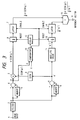
- Fig. 1 is a block diagram to show a structure of the first embodiment of a movement vector detection apparatus of the present invention.
- Fig. 2 is a diagram to illustrate a method to determine a block boundary using a space gradient of image.
- Fig. 3 is a block diagram to show a structure of the second embodiment of movement vector detection apparatus of the present invention.
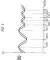
- Fig. 4 is a diagram to illustrate a method to determine a block boundary using a time gradient of image.
- Fig. 5 is a block diagram of the third embodiment to show an application of the movement vector detection apparatus of the present invention to a vibration correction apparatus of video camera.
- Fig. 6 is a block diagram of the fourth embodiment to show another application of the movement vector detection apparatus of the present invention to a vibration correction apparatus of video camera.
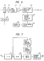
- Fig. 7 is a block diagram to show a structure of the fifth embodiment of movement vector detection apparatus of the present invention.
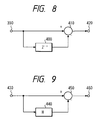
- Fig. 8 is a block diagram to show a circuit structure to obtain a gradient in the horizontal direction.
- Fig. 9 is a block diagram to show a circuit structure to obtain a gradient in the vertical direction.
- Fig. 10 is a block diagram to show a structure of the sixth embodiment.
- Fig. 11 is a circuit structure diagram to obtain a density difference between two images.
- Fig. 1 is a block diagram showing an embodiment of an image pick-up device of the present invention.
- Fig. 1, 1 denotes an input terminal of image signal
- 2 a preliminary processing filter composed of a low pass filter to effect preliminary processing of input signal
- 3 a memory to store an image signal either during one field or during one frame
- 4a substractor to compute an image density difference at corresponding positions either between two sequential fields or between two sequential frames
- 5 a multiplier
- 6, 13 summation circuits to sum up consecutive input data until a reset signal is received
- 7, 14 latch circuits to hold the input data input from the summation circuits 6, 13, respectively until an enable signal is received
- 8 a memory to store the image signal during a period necessary for operation of space gradient of image
- 9 a sign output circuit to output only data about the sign of the input signal
- 10 a comparator to compare the input data with zero
- 11 an absolute value output circuit to obtain the absolute value of space gradient of image
- 12 a delay circuit to produce a time difference between the reset and the enable signals
- 15 a divider
- 16 a movement vector output terminal.
- An image signal entering the image signal input terminal 1 is supplied to the preliminary processing filter 2 commonly composed of a low pass filter, where processes are effected to decrease influence of noises in the image signal and to smooth steep space gradients.
- the image signal is divided into two.
- One signal is supplied to the memory 3 and the subtracter 4.
- the image signal is delayed by a determined time through the memory 3.
- the subtracter 4 subtracts the delayed signal from the image output signal of the filter 2. Accordingly, a density difference or time gradient d is obtained between two chronologically sequential images.
- the time gradient d of image output from the subtractor 4 is input into the multiplier 5, then multiplied by the sign output from the sign output circuit 9, and further input into the summation circuit 6.
- the input data from the multiplier 5 into the summation circuit 6, d ⁇ sign(g′), is summed up until a reset signal enters the circuit 6.
- the sum signal is supplied to the latch circuit 7 and then to the divider 15 as a numerator for the division operation.
- the other output from the filter 2 is supplied to the memory 8 and the subtracter 4.
- the image signal delayed through the memory 8 is subtracted from the filter output, so that a space gradient of image, g′, is obtained.
- the image space gradient g′ is further divided into three: one to the sign output circuit 9 to multiply the time gradient d by the sign of the space gradient; another to the comparator 10 to gain a timing for supplying the reset and the enable signals to the summation circuits 6, 13 and the latch circuits 7, 14, respectively; and the other to the absolute value circuit 11 to obtain its absolute value, then to the summation circuit 13 to be summed up until the reset signal is received from the comparator 10, further to the latch circuit 14, and finally to the divider 15 as a denominator for the division operation.
- a movement vector of image is obtained by dividing the summation in the detection block of d ⁇ sign(g′), which is gained by multiplying the latched time gradient d in the latch circuit 7 by the sign (g′) output from the sign output circuit 9, by the summation of the absolute value of the space gradient
- the space gradient of image g′ is compared with zero, and then the reset and the enable signals are generated when the gradient g′ becomes either equal to zero or nearly equal to zero.
- the reset signals must be generated after the enable signals by the time during which the latched data in the latch circuits 7, 14 can enter the divider 15. Therefore, the signal from the comparator 10 passes through the delay circuit 12 to attain the delay of the above time. The delayed signal is supplied to the summation circuits 6, 13 as the reset signal.
- Fig. 2 shows an arbitrary section of an image.
- the ordinate represents an image density value and the abscissa a position in the image.
- Characters x1, x2, x3,..., x8 on the abscissa correspond to points where g′ (x1 ) ⁇ g′ (x2 ) ⁇ ... ⁇ g′ (x8 ) ⁇ 0.
- a block boundary is a point where the space gradient of image is either equal to or nearly equal to zero.
- block 1 can be set between x1 and x2, block 2 between x2 and x3, and so on. In this manner, an optimum block size and two-dimensional shape may be automatically determined in response to a space frequency of image.
- a half of the image period T is assigned as a block size in Fig. 2. It is also possible to assign a fall image period T as a block size.
- a small block size may be applied to the high frequency region sufficient of the space gradient information, so that the verboseness of the space gradient information, which may occur in the block of fixed dimension and shape in the conventional methods, may be effectively reduced. As a result, a high space resolution may be attained.
- the present invention allows to exclude the area of near-zero space gradient from the operation region of the time space gradient method if the block boundary is set at the near-zero space gradient.
- Such near-zero space gradient area usually provides extremely poor information of space gradient, or, even in case of having rich information of space gradient, corresponds to a region where the sign of space gradient is reversed. Since time space gradient method is theoretically weak in such region, the region may be automatically eliminated by setting said region as a spacing between two blocks.
- the present invention attained the optimization of detection block of space gradient information in response to a space gradient of input image, increasing the precision of movement vector detection.
- a boundary of detection block was determined by using the space gradient of image.
- the second embodiment shows another automatic setting method to set suitable dimension and shape of a block in response to a space frequency of input image signal, using a density difference between two sequential images.
- Fig. 3 illustrates the second embodiment, differing in input signal into a comparator 10 from the first embodiment as shown in Fig. 1.
- a density difference or time gradient d between sequential images is computed by a memory 3 and a subtractor 4, and is supplied to the comparator 10 to compare the time gradient with zero.
- a reset signal is sent to a summation circuit 6 via a delay circuit 12, and an enable signal to a latch circuit 7.
- Fig. 4 illustrates a manner of the embodiment.
- the ordinate represents an image density value and the abscissa a position in an image.
- characters x1, x2,..., x8 represent points where the time density difference between chronologically sequential images, or time gradient d, becomes zero.
- a boundary of block is set at each point of x1, x2, ..., x8. This automatically determines optimum block dimension and two-dimensional shape in response to a space frequency of image.
- the region where the time gradient d is nearly zero is eliminated from the operation area of the time space gradient method.
- Such region often provides little information of space gradient. Even if the space gradient information is sufficient, the sign of space gradient may change in such region.
- the time space gradient method is theoretically weak in said region.
- the present invention automatically eliminates said region from the operation area as a spacing between the blocks.
- the movement vector detecting apparatus of the present invention is structured as explained above.
- the movement vector detecting apparatus is applied to a vibratory motion correction device in a video camera.
- Fig. 5 is a block diagram to illustrate the third embodiment where the movement vector detecting apparatus of the present invention is used for a vibratory motion correction device of a video camera.
- 101 denotes a photographing lens optical system
- 102 an image pickup element such as a CCD to output a photoelectrically converted image signal of a subject image focused on an image pickup screen by the photographing lens system 101
- 103 a preamplifier to amplify up to a determined level the image signal output from the image pickup element 103
- 104 a camera signal preliminary processing circuit to apply AGC to the input image signal to hold a constant level thereof and to effect camera signal processing such as gamma control
- 105 an A/D converter to convert the input analog image signal to a digital image signal
- 106 an image memory to store at least one field of the digital image signal output from the A/D converter 105
- 107 a memory control circuit to control an address, an A/D conversion rate and a write-in rate upon reading the image into the image memory 106 and to control a read-out address and a read-out rate upon reading the image out of the image memory 106.
- the operation of the memory control circuit 107 is controlled by
- 108 is a movement vector detecting circuit to detect a movement vector of image from the image signal.
- the inner structure and the operation of the circuit 108 are shown in Figs. 1 and 3. It should be, however, noted that the processing is conducted by the digital signal.
- the system control circuit 109 denotes the system control circuit to totally control the present device.
- the system control circuit 109 comprises a microcomputer to compute a movement direction and a movement amount of image from the movement vector information obtained in the movement vector detecting circuit 108, and to compute vibration correction information to correct the vibratory motion. Further, the circuit 109 controls the memory control circuit 107 based on the above operation result to control the read-out out of the memory 106 so as to kill the vibratory motion by shifting the read-out position or address on the memory in the direction of the vibratory motion. That is, the memory is given an image of wider angle of view than the output image, and the read-out region is varied on the memory upon the read-out to correct the motion. The read-out region is shifted in the direction of the motion so that the movement of image is corrected effectively.
- Number 110 denotes a digital camera signal processing circuit to effect predetermined signal processing on the read-out image signal from the memory 106 to convert the signal into a normalized image signal, and 111 an angle-of-view correction circuit controlled by the system control circuit 109 to correct the angle of view of the image read-out of the memory 106. Since the read-out position of image was shifted on the memory 106 for the vibration correction, the read-out image has a smaller angle of view by the shift on the memory than the input image of the memory. Therefore, the angle-of-view correction circuit 111 conducts the processinig of magnification of view angle and compensation of image so that the image has the same angle of view as one before the vibration correction.
- the signal after the view angle correction is converted into an analog image signal by a D/A converter 112, and then supplied to an unshown monitor of video recorder, electronic view finder or the like.
- the signal may be output as a digital video output signal without use of the D/A converter 112.
- the vibration correction is so attained that the amount of vibratory motion is detected by obtaining the movement vector using the embodiments as shown in Figs. 1 and 3, and then that the read-out address is shifted in the direction to kill the vibration amount.
- the above arrangement may be modified to place the camera signal processing circuit after the D/A converter 112.
- the digital signal processing is more advantageous for the processing and in a sense of noises.
- Fig. 6 is a block diagram to illustrate another example of video camera with a vibratory motion correction device using the movement vector detecting circuit of the present invention.
- the same components as in Fig. 5 have the same numbers and are omitted to explain.
- 201 is a variable vertical angle prism to correct a vibratory motion by varying the vertical angle or direction of the optical axis thereof.
- the prism is an arrangement that silicone base liquid is sealed between two parallel glass plates to make variable the angle therebetween or vertial angle.
- Number 202 is a camera signal processing circuit to output a normalized image signal converted from the output signal of the preamp, and 203 a system control circuit comprising a microcomputer to detect a direction and an amount of vibratory motion from the movement vector information supplied from the movement vector detecting circuit 108 and to compute an amount of driving of the variable vertical angle prism for the vibration correction.
- the correction information computed in the circuit 203 is supplied to the drive circuit 204, and an actuator 205 to vary the prism is driven in the direction and by the amount to kill the vibratory motion.
- the vibration correction is so attained that the vibration amount is computed by detecting the movement vector from the image signal, and further that the variable vertical angle prism is driven in the direction to correct the amount of vibratory motion.
- a movement vector operation region is suitably and automatically set in response to a space frequency of input image. This allows the elimination of a great error vector even in an area of undistinguishable pattern, which, in turn, leads to high space resolution with effective use of the space gradient information of image.
- the detection precision may increase by eliminating from the operation region the sign changing area of the space gradient as a spacing between the detection blocks, since the time space gradient method is not well applied therein. Therefore, the vibration correction may be attained with high precision and secure operation.
- the movement vector detecting circuit of the present invention attained the vibration correction of video camera.
- many applications may be considered using the movement detection, for instance, a panning detection of camera and the like.
- the present invention realized a video camera with a high performance vibration correction device which has a very wide range of movement detection and can perform the detection and the correction of various movement.
- the movement vector detecting apparatus of the present invention is arranged to suitably and automatically set the movement vector operation region is response to the space frequency of input image, so that a big error vector may be securely eliminated in the area of the undistinguishable pattern and that the high space resolution may be obtained effectively using the space gradient information of image.
- the block boundary is determined by the simple objective function, that the block may be defined at a high speed.
- the sign changing area of the space gradient where the conventional time space gradient method is weak, may be readily eliminated as a spacing between the blocks, that the detection precision may be increased.
- the above embodiments are examples in which the movement vector detecting apparatus of the present invention employs the movement vector detection of the time space gradient method.
- the next example shows the movement vector detection using the block matching method.
- Fig. 7 is a block diagram to show the fifth embodiment, suitably applicable for the image pickup means of video camera, electronic camera or the like, where the present invention is applied to the movement vector detecting apparatus of the matching method.
- 310 is an input terminal, 320 a preliminary processing filter before the movement vector operation, 330 a circuit for computing a space gradient of image, 340 a boundary determination circuit to determine a boundary of block, 350 a delay circuit to adjust a timing with respect to the operation time of the space gradient operation circuit 330 and the block boundary determination circuit 340, 360 an analog switch which is controlled to open or close by the output from the circuit 340, 370 a movement vector operation circuit of the correlation function operation, and 380 an output terminal to output a signal of the final movement vector.
- the image signal input into the input terminal 310 passes through the preliminary processing filter 320 to eliminate a component of space frequency unfit for the correlation function operation or matching operation, e.g. a component of extremely high space frequency and a component of low frequency close to a direct current.
- the image signal is separated to the space gradient operation circuit 330 and to the delay circuit 350.
- the vertical and the horizontal space gradients are computed in the space gradient operation circuit 330.
- Fig. 8 depicts an example of a simple circuit arrangement to operate the horizontal space gradient.
- an image signal enters an image signal input terminal 390.
- a branched image signal passes through a latch 400 to be delayed by a time of one pixel.
- a subtractor 410 subtracts the delayed signal from the first input signal.
- the difference after the subtraction is output from an output terminal 420. This means that a luminance difference is obtained between two horizontally adjacent pixels.
- Fig. 9 shows an example of a simple circuit arrangement to operate the vertical space gradient.
- An image signal enters an image signal input terminal 430.
- a branched image signal passes through a line memory 440 to be delayed by a time of one scan line.
- a subtracter 450 subtracts the delayed signal from the first input signal. The difference after the subtraction is output from an output terminal 460. This means that a luminance difference is obtained between two vertically adjacent pixels.
- the block boundary determination circuit 340 stores positions where the luminance difference computed at the space gradient operation circuit 330 becomes zero or below a predetermined threshold value. Then the circuit 340 connects the positions to form a closed area or block.
- the analog switch 360 controls to perform the difference addition operation for the correlation operation within the block determined by the block boundary determination circuit 340.
- the movement vector operation circuit 370 under the control of the analog switch 360, computes a movement vector by the correlation function operation or matching operation.
- the computed movement vector is output from the output terminal 380.
- the fifth embodiment of the movement vector detecting apparatus is arranged as explained above, and has the same operation as the first embodiment as detailed referring to Fig. 2.
- the image signals g′ (x1 ) ⁇ g′ (x2 ) ⁇ ... ⁇ g′ (x8 ) ⁇ 0 at points x1, x2, ..., x8 on the abscissa a boundary is set at a point where the space gradient of image is equal to or nearly equal to zero, and then block 1 is assigned between x1 and x2, block 2 between x2 and x3, and so on.
- the dimension and the two-dimensional shape of an optimum block is automatically determined in response to the space frequency of image.
- the block size can be chosen as in Fig. 2, i.e. a half of the image period T. However, a full image period T may be also used as the block size.
- the block size may be enlarged in a low frequency area providing little image information necessary for the correlation function operation or matching operation.
- a great error vector which was a problem in the conventional methods, may be eliminated in the low frequency area.
- the block size may be set smaller in the high frequency area providing sufficient information, so that the verboseness of the space gradient information, which occurs in the conventional methods employing the fixed block size, may be reduced. As a result, the high space resolution is attained.
- the above embodiment illustrates the example using the space gradient of image for the block boundary determination means.
- the next embodiment shows another method using the density difference or time gradient between two consecutive images, which also attains the automatic setting of the dimension and the shape of the input image signal.
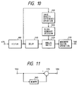
- Fig. 10 shows the sixth embodiment of the present invention.
- the sixth embodiment is different from the fifth embodiment as shown in Fig. 7 only in operation of an image density difference operation circuit 490 which is a basis to determine a block boundary in a block boundary determination circuit 500.
- Fig. 11 is an example of simple arrangement of a circuit to obtain the density difference or time gradient between two chronologically sequential images.
- An image signal enters an input terminal 550.
- a branched signal passes through a memory 560 to be delayed by one picture.
- a subtracter 570 subtracts the delayed signal from the first input signal.
- the difference is output from an output terminal 580.
- the data holding time of the memory 560 is, for example, 1/60 sec. for the field processing and 1/30 sec. for the frame processing of NTSC. Since the boundary is set at the point where the density difference is equal to zero or below the predetermined value, the optimum block shape is determined in response to the space frequency of each portion of the input image.
- the relation between the detection block and the image signal is the same as in Fig. 4.
- the density difference or time gradient d becomes zero at each of x1, x2, ..., x8 on the abscissa.
- the block boundary is set at each point of x1, x2, ..., x8, the dimension and the two-dimensional shape of the optimum block are automatically determined in response to the space frequency of image.
- the movement vector detecting apparatus of the present invention suitably and automatically sets the dimension and the shape of block for the movement vector detection area in response to the space frequency of input image, so that a great error vector may be eliminated in an undistinguishably patterned area of low space frequency, and that a high space resolution may be attained by effective use of the space gradient information of image.
- the block boundary is determined by the simple objective function to realize the high speed processing of the block setting.
Abstract
Description
- The present invention is related to a movement vector detection apparatus using an image signal.
- In an image pick-up device such as a camera, many functions must take place simultaneously and automatically, for example, automatic focusing control, automatic exposure control, automatic anti-vibration control, and so on. Techniques for such controls tend to change from those with independent sensor systems for each function to those with the capability of multiple controls, by extracting signal components as used as parameters for each function from an image signal based on a photographed image. This means that the system is made more intelligent by being enabled to operate all controls using the image signal obtained from an image pick-up means.
- Under such circumstances, the image pick-up device like a camera requires accurate, high-precision detection of motion of the image in case of automatic vibration-proof control. This is also the case in the automatic focusing control in order to obtain high precision control.
- There could be considered various methods or means detecting the image motion. Recently noticeable is a method to detect a movement vector from corresponding image signals in a detecting area, referred to hereinafter as a block, set in a screen for the movement vector detection, since it makes possible the fine detection of even complex motion with high precision.
- The time space gradient method is known to obtain the movement vector, which is described, for instance, in U.S.P. No. 3890462, Japanese Patent Publication No. 60-46878, J. O. Limb and J. A. Murphy "Measuring the Speed of Moving Object from Television Signals", and IEEE Trans. Com., Com-23, pp. 474 - 478 April 1975.
- In the time space gradient method, an amount of movement of each position is calculated by the following fundamental formulae.


- The dimension and the shape of the block are fixed for every input image.
- In the above-explained conventional method, the fixed dimension and shape of block cause a defect of extremely poor accuracy in the low space frequency area of image, since information is insufficient in the block about the space gradient necessary for operation.
- On the other hand, another defect is observed in the high space frequency area of image that the space resolution is restricted to detect the movement vector under the fixed dimension and shape of block. This is because the detection range is narrowed due to a fine period of image. A large block is unnecessary for such condition, so that the fixation of dimension and shape inevitably brings the defect.
- In addition to the above time space gradient method, there are known other methods for detecting the movement vector by the image signal processing: the mutual correlation function method to calculate the mutual correlation function coefficient, h(ξ, η); and the matching method to calculate the sum of absolute values of differences between two images as called hereinafter as a residual difference.
- The defined formula to calculate the mutual correlation function coefficient is as follows:

- For the matching method, the residual difference, e(ξ, η), is calculated as follows:

- These methods also have the same defects as the time space gradient method because of the fixed dimension and shape of the detection block: the great reduction of accuracy in the low space frequency area of image with lack of image information for the correlation function calculation in the block; and the restricted space resolution for the movement vector detection in the high space frequency area of image with the narrowed detection range under the influence of fine period of image.
- The present invention provide a solution to the above-explained problems in the conventional methods. The first purpose of the present invention is to provide a movement vector detection apparatus which can detect space gradient information of image with high precision in response to an input image.
- The second purpose of the present invention is to provide a movement vector detection apparatus which can effectively use the space gradient information of image. The apparatus automatically sets the block dimension and shape suitable for a space frequency in each portion of the input image by using a simple evaluation standard or objective function showing the space frequency of the input image.
- The third purpose of the invention is to provide a movement vector detection apparatus having high space resolution by effective use of space gradient information of image. The apparatus suitably, automatically sets a movement vector operation area in response to a space frequency of input image so that it can securely eliminate a great error vector in an undistinguishably patterned region.
- The fourth purpose of the invention is to provide a movement vector detection apparatus which can determine a block boundary by a simple objective function so as to determine a block at a high speed. In addition, the apparatus increases the detection precision, since it easily eliminates from computation a sign change region of space gradient as a spacing between blocks. The conventional time space gradient method is not well applied in such sign change region.
- According to a preferred embodiment of the present invention to attain these purposes, there will be disclosed a movement vector detection apparatus to suitably, automatically determine in a simple method an optimum block suitable for a space frequency of image, which has detection means for detecting a movement vector of image from a change in image density within a determined time at a position of image and from a space gradient of image signal at the image position, and setting means for suitably setting a dimension and a shape of unit operation area outputting the movement vector in response to the space frequency of the input image.
- The fifth purpose of the present invention is to provide a matching method movement vector detection apparatus which can suitably, automatically determine in a simple method a block suitable for a space frequency of image.
- The sixth purpose of the present invention is to provide a matching method movement vector detection apparatus which can automatically set a detection area of optimum dimension and shape suitable for a space frequency of each portion of input image by establishing a simple evaluation standard or objective function to show the space frequency of input image.
- According to a preferred embodiment of the present invention to attain these purposes, there will be disclosed a movement vector detection apparatus for detecting a movement vector from an image signal, which has area setting means for suitably, automatically setting a dimension and a shape of unit operation area outputting a movement vector in response to a space frequency of input image, and movement vector detection means for detecting the movement vector of image either by the correlation function operation or by the matching operation between chronologically sequential images from the image signal in the unit operation area set by the area setting means.
- Another purpose of the present invention is to provide a video camera with a vibration correction function which detects and corrects a vibratory motion of image by the above movement vector detection apparatus.
- Other purposes and specific features of the present invention will be clarified by the following details and drawings.
- Fig. 1 is a block diagram to show a structure of the first embodiment of a movement vector detection apparatus of the present invention.
- Fig. 2 is a diagram to illustrate a method to determine a block boundary using a space gradient of image.
- Fig. 3 is a block diagram to show a structure of the second embodiment of movement vector detection apparatus of the present invention.
- Fig. 4 is a diagram to illustrate a method to determine a block boundary using a time gradient of image.
- Fig. 5 is a block diagram of the third embodiment to show an application of the movement vector detection apparatus of the present invention to a vibration correction apparatus of video camera.
- Fig. 6 is a block diagram of the fourth embodiment to show another application of the movement vector detection apparatus of the present invention to a vibration correction apparatus of video camera.
- Fig. 7 is a block diagram to show a structure of the fifth embodiment of movement vector detection apparatus of the present invention.
- Fig. 8 is a block diagram to show a circuit structure to obtain a gradient in the horizontal direction.
- Fig. 9 is a block diagram to show a circuit structure to obtain a gradient in the vertical direction.
- Fig. 10 is a block diagram to show a structure of the sixth embodiment.
- Fig. 11 is a circuit structure diagram to obtain a density difference between two images.
- Preferred embodiments of the present invention are detailed below with reference to the drawings.
- Fig. 1 is a block diagram showing an embodiment of an image pick-up device of the present invention.
- In Fig. 1, 1 denotes an input terminal of image signal, 2 a preliminary processing filter composed of a low pass filter to effect preliminary processing of input signal, 3 a memory to store an image signal either during one field or during one frame, 4a substractor to compute an image density difference at corresponding positions either between two sequential fields or between two sequential frames, 5 a multiplier, 6, 13 summation circuits to sum up consecutive input data until a reset signal is received, 7, 14 latch circuits to hold the input data input from the
summation circuits - Explained below is an operation of the circuit as shown in Fig. 1.
- An image signal entering the image
signal input terminal 1 is supplied to thepreliminary processing filter 2 commonly composed of a low pass filter, where processes are effected to decrease influence of noises in the image signal and to smooth steep space gradients. After passing thefilter 2, the image signal is divided into two. One signal is supplied to thememory 3 and thesubtracter 4. The image signal is delayed by a determined time through thememory 3. Thesubtracter 4 subtracts the delayed signal from the image output signal of thefilter 2. Accordingly, a density difference or time gradient d is obtained between two chronologically sequential images. - The time gradient d of image output from the
subtractor 4 is input into themultiplier 5, then multiplied by the sign output from thesign output circuit 9, and further input into thesummation circuit 6. - The input data from the
multiplier 5 into thesummation circuit 6, d·sign(g′), is summed up until a reset signal enters thecircuit 6. Upon the entrance of the reset signal, the sum signal is supplied to thelatch circuit 7 and then to thedivider 15 as a numerator for the division operation. - The other output from the
filter 2 is supplied to thememory 8 and thesubtracter 4. The image signal delayed through thememory 8 is subtracted from the filter output, so that a space gradient of image, g′, is obtained. The image space gradient g′ is further divided into three: one to thesign output circuit 9 to multiply the time gradient d by the sign of the space gradient; another to thecomparator 10 to gain a timing for supplying the reset and the enable signals to thesummation circuits latch circuits absolute value circuit 11 to obtain its absolute value, then to thesummation circuit 13 to be summed up until the reset signal is received from thecomparator 10, further to thelatch circuit 14, and finally to thedivider 15 as a denominator for the division operation. - In the
divider 15, a movement vector of image is obtained by dividing the summation in the detection block of d·sign(g′), which is gained by multiplying the latched time gradient d in thelatch circuit 7 by the sign (g′) output from thesign output circuit 9, by the summation of the absolute value of the space gradient |g′| in the detection block. - In the
comparator 10, the space gradient of image g′ is compared with zero, and then the reset and the enable signals are generated when the gradient g′ becomes either equal to zero or nearly equal to zero. - The reset signals must be generated after the enable signals by the time during which the latched data in the
latch circuits divider 15. Therefore, the signal from thecomparator 10 passes through thedelay circuit 12 to attain the delay of the above time. The delayed signal is supplied to thesummation circuits - Described above was the structure and the operation of the movement vector detection apparatus of the present invention. Its characteristic, operational effects are explained below.
- Fig. 2 shows an arbitrary section of an image. The ordinate represents an image density value and the abscissa a position in the image.
- Characters x₁, x₂, x₃,..., x₈ on the abscissa correspond to points where g′(x1) ≃ g′(x2) ≃ ... ≃ g′(x8)≃ 0. Suppose that a block boundary is a point where the space gradient of image is either equal to or nearly equal to zero. Then, block 1 can be set between x₁ and x₂, block 2 between x₂ and x₃, and so on. In this manner, an optimum block size and two-dimensional shape may be automatically determined in response to a space frequency of image.
- A half of the image period T is assigned as a block size in Fig. 2. It is also possible to assign a fall image period T as a block size.
- Using the above method, a great error vector, which occurs in the low frequency region and was a problem in the conventional methods, can be eliminated if a large block size is employed in the low frequency region insufficient of space gradient information for the time space gradient method.
- On the other hand, a small block size may be applied to the high frequency region sufficient of the space gradient information, so that the verboseness of the space gradient information, which may occur in the block of fixed dimension and shape in the conventional methods, may be effectively reduced. As a result, a high space resolution may be attained.
- Furthermore, the present invention allows to exclude the area of near-zero space gradient from the operation region of the time space gradient method if the block boundary is set at the near-zero space gradient. Such near-zero space gradient area usually provides extremely poor information of space gradient, or, even in case of having rich information of space gradient, corresponds to a region where the sign of space gradient is reversed. Since time space gradient method is theoretically weak in such region, the region may be automatically eliminated by setting said region as a spacing between two blocks.
- As described above, the present invention attained the optimization of detection block of space gradient information in response to a space gradient of input image, increasing the precision of movement vector detection.
- In the above embodiment, a boundary of detection block was determined by using the space gradient of image. The second embodiment as explained below shows another automatic setting method to set suitable dimension and shape of a block in response to a space frequency of input image signal, using a density difference between two sequential images.
- Fig. 3 illustrates the second embodiment, differing in input signal into a
comparator 10 from the first embodiment as shown in Fig. 1. In the second embodiment, a density difference or time gradient d between sequential images is computed by amemory 3 and asubtractor 4, and is supplied to thecomparator 10 to compare the time gradient with zero. When the time gradient becomes either equal to or nearly equal to zero, a reset signal is sent to asummation circuit 6 via adelay circuit 12, and an enable signal to alatch circuit 7. - Fig. 4 illustrates a manner of the embodiment. The ordinate represents an image density value and the abscissa a position in an image.
- In Fig. 4, characters x₁, x₂,..., x₈ represent points where the time density difference between chronologically sequential images, or time gradient d, becomes zero. Suppose that a boundary of block is set at each point of x₁, x₂, ..., x₈. This automatically determines optimum block dimension and two-dimensional shape in response to a space frequency of image.
- The embodiment as shown in Fig. 4 shows a manner which defines a boundary at d = 0. It is also effective to define a boundary at every other zero point, d = 0. That is, a block corresponds to a period T of image.
- In case that a block boundary is set at a near-zero point of time gradient d in the present invention, the region where the time gradient d is nearly zero is eliminated from the operation area of the time space gradient method.
- Such region often provides little information of space gradient. Even if the space gradient information is sufficient, the sign of space gradient may change in such region. The time space gradient method is theoretically weak in said region. The present invention automatically eliminates said region from the operation area as a spacing between the blocks.
- The movement vector detecting apparatus of the present invention is structured as explained above. Explained next is an example that the movement vector detecting apparatus is applied to a vibratory motion correction device in a video camera.
- Fig. 5 is a block diagram to illustrate the third embodiment where the movement vector detecting apparatus of the present invention is used for a vibratory motion correction device of a video camera.
- In Fig. 5, 101 denotes a photographing lens optical system, 102 an image pickup element such as a CCD to output a photoelectrically converted image signal of a subject image focused on an image pickup screen by the photographing
lens system 101, 103 a preamplifier to amplify up to a determined level the image signal output from theimage pickup element 103, 104 a camera signal preliminary processing circuit to apply AGC to the input image signal to hold a constant level thereof and to effect camera signal processing such as gamma control, 105 an A/D converter to convert the input analog image signal to a digital image signal, 106 an image memory to store at least one field of the digital image signal output from the A/D converter 105, 107 a memory control circuit to control an address, an A/D conversion rate and a write-in rate upon reading the image into theimage memory 106 and to control a read-out address and a read-out rate upon reading the image out of theimage memory 106. The operation of thememory control circuit 107 is controlled by asystem control circuit 109 as explained later. - Further, 108 is a movement vector detecting circuit to detect a movement vector of image from the image signal. The inner structure and the operation of the
circuit 108 are shown in Figs. 1 and 3. It should be, however, noted that the processing is conducted by the digital signal. -
Number 109 denotes the system control circuit to totally control the present device. Thesystem control circuit 109 comprises a microcomputer to compute a movement direction and a movement amount of image from the movement vector information obtained in the movementvector detecting circuit 108, and to compute vibration correction information to correct the vibratory motion. Further, thecircuit 109 controls thememory control circuit 107 based on the above operation result to control the read-out out of thememory 106 so as to kill the vibratory motion by shifting the read-out position or address on the memory in the direction of the vibratory motion. That is, the memory is given an image of wider angle of view than the output image, and the read-out region is varied on the memory upon the read-out to correct the motion. The read-out region is shifted in the direction of the motion so that the movement of image is corrected effectively. -
Number 110 denotes a digital camera signal processing circuit to effect predetermined signal processing on the read-out image signal from thememory 106 to convert the signal into a normalized image signal, and 111 an angle-of-view correction circuit controlled by thesystem control circuit 109 to correct the angle of view of the image read-out of thememory 106. Since the read-out position of image was shifted on thememory 106 for the vibration correction, the read-out image has a smaller angle of view by the shift on the memory than the input image of the memory. Therefore, the angle-of-view correction circuit 111 conducts the processinig of magnification of view angle and compensation of image so that the image has the same angle of view as one before the vibration correction. - The signal after the view angle correction is converted into an analog image signal by a D/
A converter 112, and then supplied to an unshown monitor of video recorder, electronic view finder or the like. The signal may be output as a digital video output signal without use of the D/A converter 112. - By the above arrangement, the vibration correction is so attained that the amount of vibratory motion is detected by obtaining the movement vector using the embodiments as shown in Figs. 1 and 3, and then that the read-out address is shifted in the direction to kill the vibration amount.
- The above arrangement may be modified to place the camera signal processing circuit after the D/
A converter 112. The digital signal processing is more advantageous for the processing and in a sense of noises. - Fig. 6 is a block diagram to illustrate another example of video camera with a vibratory motion correction device using the movement vector detecting circuit of the present invention. The same components as in Fig. 5 have the same numbers and are omitted to explain.
- In Fig. 6, 201 is a variable vertical angle prism to correct a vibratory motion by varying the vertical angle or direction of the optical axis thereof. One example of the prism is an arrangement that silicone base liquid is sealed between two parallel glass plates to make variable the angle therebetween or vertial angle.
-
Number 202 is a camera signal processing circuit to output a normalized image signal converted from the output signal of the preamp, and 203 a system control circuit comprising a microcomputer to detect a direction and an amount of vibratory motion from the movement vector information supplied from the movementvector detecting circuit 108 and to compute an amount of driving of the variable vertical angle prism for the vibration correction. The correction information computed in thecircuit 203 is supplied to thedrive circuit 204, and anactuator 205 to vary the prism is driven in the direction and by the amount to kill the vibratory motion. As above, the vibration correction is so attained that the vibration amount is computed by detecting the movement vector from the image signal, and further that the variable vertical angle prism is driven in the direction to correct the amount of vibratory motion. - In either of the above embodiments, a movement vector operation region is suitably and automatically set in response to a space frequency of input image. This allows the elimination of a great error vector even in an area of undistinguishable pattern, which, in turn, leads to high space resolution with effective use of the space gradient information of image. The detection precision may increase by eliminating from the operation region the sign changing area of the space gradient as a spacing between the detection blocks, since the time space gradient method is not well applied therein. Therefore, the vibration correction may be attained with high precision and secure operation.
- As explained, the movement vector detecting circuit of the present invention attained the vibration correction of video camera. In addition to the vibration correction, many applications may be considered using the movement detection, for instance, a panning detection of camera and the like.
- The present invention realized a video camera with a high performance vibration correction device which has a very wide range of movement detection and can perform the detection and the correction of various movement.
- As explained, the movement vector detecting apparatus of the present invention is arranged to suitably and automatically set the movement vector operation region is response to the space frequency of input image, so that a big error vector may be securely eliminated in the area of the undistinguishable pattern and that the high space resolution may be obtained effectively using the space gradient information of image.
- Also, the block boundary is determined by the simple objective function, that the block may be defined at a high speed.
- The sign changing area of the space gradient, where the conventional time space gradient method is weak, may be readily eliminated as a spacing between the blocks, that the detection precision may be increased.
- The above embodiments are examples in which the movement vector detecting apparatus of the present invention employs the movement vector detection of the time space gradient method. The next example shows the movement vector detection using the block matching method.
- Fig. 7 is a block diagram to show the fifth embodiment, suitably applicable for the image pickup means of video camera, electronic camera or the like, where the present invention is applied to the movement vector detecting apparatus of the matching method.
- In Fig. 7, 310 is an input terminal, 320 a preliminary processing filter before the movement vector operation, 330 a circuit for computing a space gradient of image, 340 a boundary determination circuit to determine a boundary of block, 350 a delay circuit to adjust a timing with respect to the operation time of the space
gradient operation circuit 330 and the blockboundary determination circuit circuit 340, 370 a movement vector operation circuit of the correlation function operation, and 380 an output terminal to output a signal of the final movement vector. - The image signal input into the
input terminal 310 passes through thepreliminary processing filter 320 to eliminate a component of space frequency unfit for the correlation function operation or matching operation, e.g. a component of extremely high space frequency and a component of low frequency close to a direct current. After passing thepreliminary processing filter 320, the image signal is separated to the spacegradient operation circuit 330 and to thedelay circuit 350. The vertical and the horizontal space gradients are computed in the spacegradient operation circuit 330. Fig. 8 depicts an example of a simple circuit arrangement to operate the horizontal space gradient. In Fig. 8, an image signal enters an imagesignal input terminal 390. A branched image signal passes through alatch 400 to be delayed by a time of one pixel. Asubtractor 410 subtracts the delayed signal from the first input signal. The difference after the subtraction is output from anoutput terminal 420. This means that a luminance difference is obtained between two horizontally adjacent pixels. - Fig. 9 shows an example of a simple circuit arrangement to operate the vertical space gradient. An image signal enters an image
signal input terminal 430. A branched image signal passes through aline memory 440 to be delayed by a time of one scan line. Asubtracter 450 subtracts the delayed signal from the first input signal. The difference after the subtraction is output from anoutput terminal 460. This means that a luminance difference is obtained between two vertically adjacent pixels. - The block
boundary determination circuit 340 stores positions where the luminance difference computed at the spacegradient operation circuit 330 becomes zero or below a predetermined threshold value. Then thecircuit 340 connects the positions to form a closed area or block. Theanalog switch 360 controls to perform the difference addition operation for the correlation operation within the block determined by the blockboundary determination circuit 340. - The movement
vector operation circuit 370, under the control of theanalog switch 360, computes a movement vector by the correlation function operation or matching operation. The computed movement vector is output from theoutput terminal 380. - The fifth embodiment of the movement vector detecting apparatus is arranged as explained above, and has the same operation as the first embodiment as detailed referring to Fig. 2. In summary, the image signals g′(x1) ≃ g′(x2) ≃ ..... ≃ g′(x8) ≃ 0 at points x₁, x₂, ..., x₈ on the abscissa, a boundary is set at a point where the space gradient of image is equal to or nearly equal to zero, and then block 1 is assigned between x₁ and x₂, block 2 between x₂ and x₃, and so on. The dimension and the two-dimensional shape of an optimum block is automatically determined in response to the space frequency of image.
- The block size can be chosen as in Fig. 2, i.e. a half of the image period T. However, a full image period T may be also used as the block size.
- The block size may be enlarged in a low frequency area providing little image information necessary for the correlation function operation or matching operation. By this arrangement, a great error vector, which was a problem in the conventional methods, may be eliminated in the low frequency area. Furthermore, the block size may be set smaller in the high frequency area providing sufficient information, so that the verboseness of the space gradient information, which occurs in the conventional methods employing the fixed block size, may be reduced. As a result, the high space resolution is attained.
- The above embodiment illustrates the example using the space gradient of image for the block boundary determination means. The next embodiment shows another method using the density difference or time gradient between two consecutive images, which also attains the automatic setting of the dimension and the shape of the input image signal.
- Fig. 10 shows the sixth embodiment of the present invention. The sixth embodiment is different from the fifth embodiment as shown in Fig. 7 only in operation of an image density
difference operation circuit 490 which is a basis to determine a block boundary in a blockboundary determination circuit 500. - Fig. 11 is an example of simple arrangement of a circuit to obtain the density difference or time gradient between two chronologically sequential images. An image signal enters an
input terminal 550. A branched signal passes through amemory 560 to be delayed by one picture. Asubtracter 570 subtracts the delayed signal from the first input signal. The difference is output from anoutput terminal 580. The data holding time of thememory 560 is, for example, 1/60 sec. for the field processing and 1/30 sec. for the frame processing of NTSC. Since the boundary is set at the point where the density difference is equal to zero or below the predetermined value, the optimum block shape is determined in response to the space frequency of each portion of the input image. - The relation between the detection block and the image signal is the same as in Fig. 4. The density difference or time gradient d becomes zero at each of x₁, x₂, ..., x₈ on the abscissa. When the block boundary is set at each point of x₁, x₂, ..., x₈, the dimension and the two-dimensional shape of the optimum block are automatically determined in response to the space frequency of image. Fig. 4 shows the example in which the block is defined by every point of d = 0. It is also possible to define the block using every other point of d = 0, where one block corresponds to one period T of image. It should be noted that this embodiment is also applicable to the vibration-proof device or the like of video camera, as shown in Figs. 5 and 6.
- As detailed above, the movement vector detecting apparatus of the present invention suitably and automatically sets the dimension and the shape of block for the movement vector detection area in response to the space frequency of input image, so that a great error vector may be eliminated in an undistinguishably patterned area of low space frequency, and that a high space resolution may be attained by effective use of the space gradient information of image. Moreover, the block boundary is determined by the simple objective function to realize the high speed processing of the block setting.
Claims (10)
- A movement vector detection apparatus comprising:
detection means for detecting a movement vector of an image with relation to a change amount of image density value in a determined time at an arbitrary position of the image and a space gradient of image signal at said arbitrary position, and
setting means for suitably setting a dimension and a shape of a unit operation area to output said movement vector in response to a space frequency of the input image. - A movement vector detection apparatus according to Claim 1, where said setting means is arranged to determine a boundary of said unit operation area in use of the space gradient of image.
- A movement vector detection apparatus according to Claim 1, where said setting means is arranged to determine a boundary of said unit operation area in use of a density difference between chronologically sequential images.
- A movement vector detection apparatus detecting a movement vector from an image signal;
area setting means for suitably, autometically setting a dimension and a shape of a unit operation area to output a movement vector in response to a space frequency of an input image; and
movement vector detecting means for detecting the movement vector of image by effecting the correlation function operation or the matching operation between chronologically sequential images from the image signal of said unit operation area set by said area setting means. - A movement vector detection apparatus according to Claim 4, where said area setting means is arranged to determine a boundary of said unit operation area based on a space gradient of image.
- A movement vector detection apparatus according to Claim 4, where said area setting means is arranged to determine a boundary of said unit operation area based on a time gradient represented by a density difference between chronologically sequential images.
- A camera having automatically controlled functions, characterised by:
movement detection means, wherein the operation of at least one of said control functions is modified in response to an output from said movement detection means. - A camera according to claim 7, wherein a movement vector is generated in response to detecting a change in image density at a predetermined area of the image.
- A camera according to claim 8, wherein the selection of said predetermined area is made in response to a space frequency of the image.
- A camera according to any of claims 7 to 9, wherein said camera is a video camera or an electronic still camera.
Applications Claiming Priority (4)
| Application Number | Priority Date | Filing Date | Title |
|---|---|---|---|
| JP333838/90 | 1990-11-30 | ||
| JP2333838A JPH04207480A (en) | 1990-11-30 | 1990-11-30 | Moving vector detector |
| JP15031991A JP3200089B2 (en) | 1991-06-21 | 1991-06-21 | Motion vector detection device and shake correction device |
| JP150319/91 | 1991-06-21 |
Publications (3)
| Publication Number | Publication Date |
|---|---|
| EP0488723A2 true EP0488723A2 (en) | 1992-06-03 |
| EP0488723A3 EP0488723A3 (en) | 1992-07-29 |
| EP0488723B1 EP0488723B1 (en) | 1997-02-26 |
Family
ID=26479960
Family Applications (1)
| Application Number | Title | Priority Date | Filing Date |
|---|---|---|---|
| EP91311002A Expired - Lifetime EP0488723B1 (en) | 1990-11-30 | 1991-11-28 | Movement vector detection apparatus |
Country Status (3)
| Country | Link |
|---|---|
| US (1) | US5734441A (en) |
| EP (1) | EP0488723B1 (en) |
| DE (1) | DE69124777T2 (en) |
Cited By (2)
| Publication number | Priority date | Publication date | Assignee | Title |
|---|---|---|---|---|
| EP0617549A1 (en) * | 1993-03-26 | 1994-09-28 | Canon Kabushiki Kaisha | Multi-eye image displaying apparatus |
| CN107072548A (en) * | 2014-11-03 | 2017-08-18 | 皇家飞利浦有限公司 | For people orientation and/or position automatic detection equipment, system and method |
Families Citing this family (47)
| Publication number | Priority date | Publication date | Assignee | Title |
|---|---|---|---|---|
| JPH07135594A (en) * | 1993-11-11 | 1995-05-23 | Canon Inc | Image pickup controller |
| JP3450449B2 (en) * | 1994-07-18 | 2003-09-22 | キヤノン株式会社 | Imaging device and imaging method thereof |
| US6111609A (en) * | 1995-01-05 | 2000-08-29 | Thomson Licensing S.A. | Electronic recording camera with reduced power consumption |
| US6573930B2 (en) * | 1996-11-15 | 2003-06-03 | Canon Kabushiki Kaisha | Image pickup apparatus for storing, reading-out and processing a signal during predetermined time periods |
| US5943445A (en) * | 1996-12-19 | 1999-08-24 | Digital Equipment Corporation | Dynamic sprites for encoding video data |
| KR100255648B1 (en) * | 1997-10-10 | 2000-05-01 | 윤종용 | Video motion detection apparatus and method by gradient pattern matching |
| KR20010085748A (en) * | 1998-08-28 | 2001-09-07 | 윌리암 제이. 버크 | Method and apparatus for electronically enhancing images |
| GB2370709A (en) * | 2000-12-28 | 2002-07-03 | Nokia Mobile Phones Ltd | Displaying an image and associated visual effect |
| US7953219B2 (en) * | 2001-07-19 | 2011-05-31 | Nice Systems, Ltd. | Method apparatus and system for capturing and analyzing interaction based content |
| AU2002334356A1 (en) * | 2001-09-06 | 2003-03-18 | Nice Systems Ltd. | Recording of interactions between a customer and a sales person at a point of sales |
| US7728870B2 (en) | 2001-09-06 | 2010-06-01 | Nice Systems Ltd | Advanced quality management and recording solutions for walk-in environments |
| WO2003028358A2 (en) * | 2001-09-24 | 2003-04-03 | Nice Systems Ltd. | System and method for the automatic control of video frame rate |
| WO2003067884A1 (en) * | 2002-02-06 | 2003-08-14 | Nice Systems Ltd. | Method and apparatus for video frame sequence-based object tracking |
| EP1472869A4 (en) * | 2002-02-06 | 2008-07-30 | Nice Systems Ltd | System and method for video content analysis-based detection, surveillance and alarm management |
| US20050128304A1 (en) * | 2002-02-06 | 2005-06-16 | Manasseh Frederick M. | System and method for traveler interactions management |
| US7436887B2 (en) * | 2002-02-06 | 2008-10-14 | Playtex Products, Inc. | Method and apparatus for video frame sequence-based object tracking |
| AU2003209654A1 (en) | 2002-03-07 | 2003-09-16 | Nice Systems Ltd. | Method and apparatus for internal and external monitoring of a transportation vehicle |
| US8594249B2 (en) * | 2002-09-26 | 2013-11-26 | Intel Mobile Communications GmbH | Device and method for detecting a useful signal by detecting a periodic signal contained in the useful signal |
| AU2003219502A1 (en) | 2003-04-09 | 2004-11-01 | Nice Systems Ltd. | Apparatus, system and method for dispute resolution, regulation compliance and quality management in financial institutions |
| US7546173B2 (en) * | 2003-08-18 | 2009-06-09 | Nice Systems, Ltd. | Apparatus and method for audio content analysis, marking and summing |
| WO2005046195A1 (en) * | 2003-11-05 | 2005-05-19 | Nice Systems Ltd. | Apparatus and method for event-driven content analysis |
| EP1712183A4 (en) * | 2003-12-16 | 2009-07-08 | Hitachi Medical Corp | Ultrasonographic bio-movement detection device, image presentation device using the same, and ultrasonographic curing device |
| KR100750424B1 (en) * | 2004-03-03 | 2007-08-21 | 닛본 덴끼 가부시끼가이샤 | Image similarity calculation system, image search system, image similarity calculation method, and image similarity calculation program |
| US20050204378A1 (en) * | 2004-03-10 | 2005-09-15 | Shay Gabay | System and method for video content analysis-based detection, surveillance and alarm management |
| US7086139B2 (en) * | 2004-04-30 | 2006-08-08 | Hitachi Global Storage Technologies Netherlands B.V. | Methods of making magnetic write heads using electron beam lithography |
| US8204884B2 (en) * | 2004-07-14 | 2012-06-19 | Nice Systems Ltd. | Method, apparatus and system for capturing and analyzing interaction based content |
| WO2006021943A1 (en) * | 2004-08-09 | 2006-03-02 | Nice Systems Ltd. | Apparatus and method for multimedia content based |
| US8724891B2 (en) * | 2004-08-31 | 2014-05-13 | Ramot At Tel-Aviv University Ltd. | Apparatus and methods for the detection of abnormal motion in a video stream |
| US8078463B2 (en) * | 2004-11-23 | 2011-12-13 | Nice Systems, Ltd. | Method and apparatus for speaker spotting |
| US20060179064A1 (en) * | 2005-02-07 | 2006-08-10 | Nice Systems Ltd. | Upgrading performance using aggregated information shared between management systems |
| US8005675B2 (en) * | 2005-03-17 | 2011-08-23 | Nice Systems, Ltd. | Apparatus and method for audio analysis |
| WO2006106496A1 (en) * | 2005-04-03 | 2006-10-12 | Nice Systems Ltd. | Apparatus and methods for the semi-automatic tracking and examining of an object or an event in a monitored site |
| US7386105B2 (en) * | 2005-05-27 | 2008-06-10 | Nice Systems Ltd | Method and apparatus for fraud detection |
| US20080040110A1 (en) * | 2005-08-08 | 2008-02-14 | Nice Systems Ltd. | Apparatus and Methods for the Detection of Emotions in Audio Interactions |
| US7716048B2 (en) * | 2006-01-25 | 2010-05-11 | Nice Systems, Ltd. | Method and apparatus for segmentation of audio interactions |
| US8725518B2 (en) * | 2006-04-25 | 2014-05-13 | Nice Systems Ltd. | Automatic speech analysis |
| WO2007135656A1 (en) * | 2006-05-18 | 2007-11-29 | Nice Systems Ltd. | Method and apparatus for combining traffic analysis and monitoring center in lawful interception |
| US7822605B2 (en) * | 2006-10-19 | 2010-10-26 | Nice Systems Ltd. | Method and apparatus for large population speaker identification in telephone interactions |
| US7631046B2 (en) * | 2006-10-26 | 2009-12-08 | Nice Systems, Ltd. | Method and apparatus for lawful interception of web based messaging communication |
| US7577246B2 (en) * | 2006-12-20 | 2009-08-18 | Nice Systems Ltd. | Method and system for automatic quality evaluation |
| US20080189171A1 (en) * | 2007-02-01 | 2008-08-07 | Nice Systems Ltd. | Method and apparatus for call categorization |
| US8571853B2 (en) * | 2007-02-11 | 2013-10-29 | Nice Systems Ltd. | Method and system for laughter detection |
| US7599475B2 (en) * | 2007-03-12 | 2009-10-06 | Nice Systems, Ltd. | Method and apparatus for generic analytics |
| US20090012826A1 (en) * | 2007-07-02 | 2009-01-08 | Nice Systems Ltd. | Method and apparatus for adaptive interaction analytics |
| JP5106335B2 (en) * | 2008-09-24 | 2012-12-26 | キヤノン株式会社 | Imaging apparatus, control method thereof, and program |
| US9709990B2 (en) * | 2012-12-21 | 2017-07-18 | Toyota Jidosha Kabushiki Kaisha | Autonomous navigation through obstacles |
| CN107398926B (en) * | 2017-07-18 | 2023-09-26 | 华南理工大学 | Flexible arm vibration measurement device and method based on terminal visual detection |
Citations (2)
| Publication number | Priority date | Publication date | Assignee | Title |
|---|---|---|---|---|
| EP0310032A2 (en) * | 1987-10-02 | 1989-04-05 | Nippon Hoso Kyokai | Motion detection circuit |
| EP0393823A2 (en) * | 1989-03-03 | 1990-10-24 | Matsushita Electric Industrial Co., Ltd. | Image motion vector detecting apparatus |
Family Cites Families (13)
| Publication number | Priority date | Publication date | Assignee | Title |
|---|---|---|---|---|
| US4364089A (en) * | 1979-10-31 | 1982-12-14 | Westinghouse Electric Corp. | Binary correlation video tracker |
| GB8518803D0 (en) * | 1985-07-25 | 1985-08-29 | Rca Corp | Locating target patterns within images |
| US4805018A (en) * | 1986-03-07 | 1989-02-14 | Matsushita Electric Industrial Co., Ltd. | Video signal processing apparatus for separating an image of a moving object from video signals |
| US5012270A (en) * | 1988-03-10 | 1991-04-30 | Canon Kabushiki Kaisha | Image shake detecting device |
| DE3818837A1 (en) * | 1988-06-03 | 1989-12-14 | Roehm Gmbh | COMPATIBLE POLYMER BLENDS |
| US5034986A (en) * | 1989-03-01 | 1991-07-23 | Siemens Aktiengesellschaft | Method for detecting and tracking moving objects in a digital image sequence having a stationary background |
| JP2953712B2 (en) * | 1989-09-27 | 1999-09-27 | 株式会社東芝 | Moving object detection device |
| US5018215A (en) * | 1990-03-23 | 1991-05-21 | Honeywell Inc. | Knowledge and model based adaptive signal processor |
| US5128754A (en) * | 1990-03-30 | 1992-07-07 | New York Institute Of Technology | Apparatus and method for encoding and decoding video |
| US5173770A (en) * | 1990-04-27 | 1992-12-22 | Canon Kabushiki Kaisha | Movement vector detection device |
| JP2811909B2 (en) * | 1990-04-27 | 1998-10-15 | キヤノン株式会社 | Image processing device |
| EP0454481B1 (en) * | 1990-04-27 | 1996-08-28 | Canon Kabushiki Kaisha | Movement vector detection device |
| US5596366A (en) * | 1990-05-14 | 1997-01-21 | Canon Kabushiki Kaisha | Camera apparatus having camera movement detection |
-
1991
- 1991-11-28 EP EP91311002A patent/EP0488723B1/en not_active Expired - Lifetime
- 1991-11-28 DE DE69124777T patent/DE69124777T2/en not_active Expired - Fee Related
-
1995
- 1995-03-13 US US08/402,990 patent/US5734441A/en not_active Expired - Fee Related
Patent Citations (2)
| Publication number | Priority date | Publication date | Assignee | Title |
|---|---|---|---|---|
| EP0310032A2 (en) * | 1987-10-02 | 1989-04-05 | Nippon Hoso Kyokai | Motion detection circuit |
| EP0393823A2 (en) * | 1989-03-03 | 1990-10-24 | Matsushita Electric Industrial Co., Ltd. | Image motion vector detecting apparatus |
Non-Patent Citations (1)
| Title |
|---|
| S.M.P.T.E. JOURNAL, vol. 97, no. 11, November 1988, pages 908-910, White Plains, NY, US; T. MATSUZURU et al.: "A new technique to improve video stability by digital processing" * |
Cited By (4)
| Publication number | Priority date | Publication date | Assignee | Title |
|---|---|---|---|---|
| EP0617549A1 (en) * | 1993-03-26 | 1994-09-28 | Canon Kabushiki Kaisha | Multi-eye image displaying apparatus |
| US5612709A (en) * | 1993-03-26 | 1997-03-18 | Canon Kabushiki Kaisha | Multi-eye image displaying apparatus |
| CN107072548A (en) * | 2014-11-03 | 2017-08-18 | 皇家飞利浦有限公司 | For people orientation and/or position automatic detection equipment, system and method |
| CN107072548B (en) * | 2014-11-03 | 2020-09-01 | 皇家飞利浦有限公司 | Device, system and method for automatic detection of orientation and/or position of a person |
Also Published As
| Publication number | Publication date |
|---|---|
| DE69124777T2 (en) | 1997-06-26 |
| DE69124777D1 (en) | 1997-04-03 |
| EP0488723B1 (en) | 1997-02-26 |
| US5734441A (en) | 1998-03-31 |
| EP0488723A3 (en) | 1992-07-29 |
Similar Documents
| Publication | Publication Date | Title |
|---|---|---|
| EP0488723B1 (en) | Movement vector detection apparatus | |
| US5729290A (en) | Movement detection device and focus detection apparatus using such device | |
| JP2772079B2 (en) | Automatic focusing device | |
| US7734162B2 (en) | Camera shaking correcting device, and image pickup device | |
| KR950003569B1 (en) | Photographic apparatus and automatic focusing control device using the same | |
| JP3732665B2 (en) | Automatic focus control device and focusing operation determination method thereof | |
| EP0553850A1 (en) | Automatic focussing apparatus for automatically matching focus in response to video signal | |
| EP0488721B1 (en) | Movement detection | |
| US5173770A (en) | Movement vector detection device | |
| JP3200089B2 (en) | Motion vector detection device and shake correction device | |
| EP0454483A2 (en) | Movement vector detection device | |
| JP3563508B2 (en) | Automatic focusing device | |
| JP2603212B2 (en) | Automatic tracking device in camera | |
| JPH0618779A (en) | Automatic focus detecting device | |
| JPH07209576A (en) | Optical detecting device and focus control unit | |
| JP3361619B2 (en) | Focusing position detection device for electronic camera | |
| JPH05145822A (en) | Moving body tracking device | |
| JP3397384B2 (en) | Imaging device | |
| JP3325593B2 (en) | Focus control device | |
| JP3157009B2 (en) | Motion vector detection device and blur correction device | |
| JPH03201877A (en) | Electronic camera equipment | |
| KR101486773B1 (en) | Image processing method for image-stabilization and imaging device having image-stabilization function | |
| JP2735264B2 (en) | Motion compensated imaging device | |
| JP3191945B2 (en) | camera | |
| JP3126998B2 (en) | Motion vector detection device |
Legal Events
| Date | Code | Title | Description |
|---|---|---|---|
| PUAI | Public reference made under article 153(3) epc to a published international application that has entered the european phase |
Free format text: ORIGINAL CODE: 0009012 |
|
| AK | Designated contracting states |
Kind code of ref document: A2 Designated state(s): DE FR GB |
|
| PUAL | Search report despatched |
Free format text: ORIGINAL CODE: 0009013 |
|
| AK | Designated contracting states |
Kind code of ref document: A3 Designated state(s): DE FR GB |
|
| 17P | Request for examination filed |
Effective date: 19921221 |
|
| 17Q | First examination report despatched |
Effective date: 19950105 |
|
| GRAG | Despatch of communication of intention to grant |
Free format text: ORIGINAL CODE: EPIDOS AGRA |
|
| GRAH | Despatch of communication of intention to grant a patent |
Free format text: ORIGINAL CODE: EPIDOS IGRA |
|
| GRAH | Despatch of communication of intention to grant a patent |
Free format text: ORIGINAL CODE: EPIDOS IGRA |
|
| GRAA | (expected) grant |
Free format text: ORIGINAL CODE: 0009210 |
|
| AK | Designated contracting states |
Kind code of ref document: B1 Designated state(s): DE FR GB |
|
| REF | Corresponds to: |
Ref document number: 69124777 Country of ref document: DE Date of ref document: 19970403 |
|
| ET | Fr: translation filed | ||
| PLBE | No opposition filed within time limit |
Free format text: ORIGINAL CODE: 0009261 |
|
| STAA | Information on the status of an ep patent application or granted ep patent |
Free format text: STATUS: NO OPPOSITION FILED WITHIN TIME LIMIT |
|
| 26N | No opposition filed | ||
| REG | Reference to a national code |
Ref country code: GB Ref legal event code: IF02 |
|
| PGFP | Annual fee paid to national office [announced via postgrant information from national office to epo] |
Ref country code: GB Payment date: 20041115 Year of fee payment: 14 |
|
| PGFP | Annual fee paid to national office [announced via postgrant information from national office to epo] |
Ref country code: FR Payment date: 20041126 Year of fee payment: 14 |
|
| PGFP | Annual fee paid to national office [announced via postgrant information from national office to epo] |
Ref country code: DE Payment date: 20050121 Year of fee payment: 14 |
|
| PG25 | Lapsed in a contracting state [announced via postgrant information from national office to epo] |
Ref country code: GB Free format text: LAPSE BECAUSE OF NON-PAYMENT OF DUE FEES Effective date: 20051128 |
|
| PG25 | Lapsed in a contracting state [announced via postgrant information from national office to epo] |
Ref country code: DE Free format text: LAPSE BECAUSE OF NON-PAYMENT OF DUE FEES Effective date: 20060601 |
|
| GBPC | Gb: european patent ceased through non-payment of renewal fee |
Effective date: 20051128 |
|
| PG25 | Lapsed in a contracting state [announced via postgrant information from national office to epo] |
Ref country code: FR Free format text: LAPSE BECAUSE OF NON-PAYMENT OF DUE FEES Effective date: 20060731 |
|
| REG | Reference to a national code |
Ref country code: FR Ref legal event code: ST Effective date: 20060731 |