EP0489344A1 - Method for identifying an activated key of a keyboard - Google Patents
Method for identifying an activated key of a keyboard Download PDFInfo
- Publication number
- EP0489344A1 EP0489344A1 EP91120226A EP91120226A EP0489344A1 EP 0489344 A1 EP0489344 A1 EP 0489344A1 EP 91120226 A EP91120226 A EP 91120226A EP 91120226 A EP91120226 A EP 91120226A EP 0489344 A1 EP0489344 A1 EP 0489344A1
- Authority
- EP
- European Patent Office
- Prior art keywords
- sensors
- plate
- signals
- keyboard
- terminals
- Prior art date
- Legal status (The legal status is an assumption and is not a legal conclusion. Google has not performed a legal analysis and makes no representation as to the accuracy of the status listed.)
- Withdrawn
Links
Images


Classifications
-
- H—ELECTRICITY
- H01—ELECTRIC ELEMENTS
- H01H—ELECTRIC SWITCHES; RELAYS; SELECTORS; EMERGENCY PROTECTIVE DEVICES
- H01H13/00—Switches having rectilinearly-movable operating part or parts adapted for pushing or pulling in one direction only, e.g. push-button switch
- H01H13/70—Switches having rectilinearly-movable operating part or parts adapted for pushing or pulling in one direction only, e.g. push-button switch having a plurality of operating members associated with different sets of contacts, e.g. keyboard
- H01H13/78—Switches having rectilinearly-movable operating part or parts adapted for pushing or pulling in one direction only, e.g. push-button switch having a plurality of operating members associated with different sets of contacts, e.g. keyboard characterised by the contacts or the contact sites
- H01H13/785—Switches having rectilinearly-movable operating part or parts adapted for pushing or pulling in one direction only, e.g. push-button switch having a plurality of operating members associated with different sets of contacts, e.g. keyboard characterised by the contacts or the contact sites characterised by the material of the contacts, e.g. conductive polymers
-
- H—ELECTRICITY
- H01—ELECTRIC ELEMENTS
- H01H—ELECTRIC SWITCHES; RELAYS; SELECTORS; EMERGENCY PROTECTIVE DEVICES
- H01H13/00—Switches having rectilinearly-movable operating part or parts adapted for pushing or pulling in one direction only, e.g. push-button switch
- H01H13/70—Switches having rectilinearly-movable operating part or parts adapted for pushing or pulling in one direction only, e.g. push-button switch having a plurality of operating members associated with different sets of contacts, e.g. keyboard
- H01H13/702—Switches having rectilinearly-movable operating part or parts adapted for pushing or pulling in one direction only, e.g. push-button switch having a plurality of operating members associated with different sets of contacts, e.g. keyboard with contacts carried by or formed from layers in a multilayer structure, e.g. membrane switches
-
- H—ELECTRICITY
- H03—ELECTRONIC CIRCUITRY
- H03K—PULSE TECHNIQUE
- H03K17/00—Electronic switching or gating, i.e. not by contact-making and –breaking
- H03K17/94—Electronic switching or gating, i.e. not by contact-making and –breaking characterised by the way in which the control signals are generated
- H03K17/96—Touch switches
- H03K17/9618—Touch switches using a plurality of detectors, e.g. keyboard
-
- H—ELECTRICITY
- H03—ELECTRONIC CIRCUITRY
- H03K—PULSE TECHNIQUE
- H03K17/00—Electronic switching or gating, i.e. not by contact-making and –breaking
- H03K17/94—Electronic switching or gating, i.e. not by contact-making and –breaking characterised by the way in which the control signals are generated
- H03K17/96—Touch switches
- H03K17/9625—Touch switches using a force resistance transducer
-
- H—ELECTRICITY
- H03—ELECTRONIC CIRCUITRY
- H03M—CODING; DECODING; CODE CONVERSION IN GENERAL
- H03M11/00—Coding in connection with keyboards or like devices, i.e. coding of the position of operated keys
- H03M11/22—Static coding
-
- H—ELECTRICITY
- H01—ELECTRIC ELEMENTS
- H01H—ELECTRIC SWITCHES; RELAYS; SELECTORS; EMERGENCY PROTECTIVE DEVICES
- H01H2201/00—Contacts
- H01H2201/022—Material
- H01H2201/032—Conductive polymer; Rubber
- H01H2201/036—Variable resistance
-
- H—ELECTRICITY
- H01—ELECTRIC ELEMENTS
- H01H—ELECTRIC SWITCHES; RELAYS; SELECTORS; EMERGENCY PROTECTIVE DEVICES
- H01H2219/00—Legends
- H01H2219/002—Legends replaceable; adaptable
-
- H—ELECTRICITY
- H01—ELECTRIC ELEMENTS
- H01H—ELECTRIC SWITCHES; RELAYS; SELECTORS; EMERGENCY PROTECTIVE DEVICES
- H01H2227/00—Dimensions; Characteristics
- H01H2227/002—Layer thickness
- H01H2227/004—Membrane
-
- H—ELECTRICITY
- H01—ELECTRIC ELEMENTS
- H01H—ELECTRIC SWITCHES; RELAYS; SELECTORS; EMERGENCY PROTECTIVE DEVICES
- H01H2231/00—Applications
- H01H2231/034—Coordinate determination
-
- H—ELECTRICITY
- H01—ELECTRIC ELEMENTS
- H01H—ELECTRIC SWITCHES; RELAYS; SELECTORS; EMERGENCY PROTECTIVE DEVICES
- H01H2239/00—Miscellaneous
- H01H2239/038—Anti-vandalism
Definitions
- the present invention relates to a keypad for a control panel comprising a base plate, a decor plate provided with identification markings of keys to which very specific functions are assigned, as well as sensors sensitive to an activation pressure arranged below each key between the base plate and the decor plate.
- the invention also relates to a method for identifying an activated key of a keyboard consisting of a grid of m lines and n columns of keys of such a keyboard.
- the invention relates in particular to keyboards for control panels intended to trigger and supervise operations and operations of all kinds of machines, apparatus, installations, etc.
- a keyboard of this kind is, for example, known from patent application EP-0 210 386 which proposes a control panel, of laminated structure, comprising a hard sheet or plate forming a support with a covering layer between which is disposed in sandwich a crystal which reacts to an external pressure by the emission or modification of an electrical signal.
- EP-0 366 832 proposes a cover for a keyboard with keys of a control panel which is in the form of a rigid plate which can be deposited on the operating surface of the keyboard and which has in the corresponding places at the keyboard keys at least one pressure transmission zone which is flexible or of reduced rigidity.
- keyboards have certain disadvantages, depending on their type of application.
- these keyboards with keys or control panels are sensitive to external mechanical influences and can be easily damaged due to blows or ill-treatment.
- the known keyboards are relatively sensitive to external vibrations.
- Such a sensor essentially consists of a thin semiconductor film which can be formed by tiny particles, for example of molybdenum disulphide with a size of the order of 1 to 10 microns embedded in a support resin.
- Such a film has a certain surface resistance which, when the film is applied against a conductive surface can be reduced as a result of an increase in the number of points of contact with this conductive surface under the effect of localized pressure.
- An advantageous embodiment consists in associating such an FSR film with a film on which a conductive network is deposited in the form of two combs of electrodes in interdigital arrangement. These two films are sealed to each other so that the electrode combs touch the surface of the FSR semiconductor layer.
- the resistance between the terminals of the electrode combs is very high, generally of the order of several megaohms.
- the FSR is subjected to a force perpendicular to its surface, the resistance decreases approximately exponentially.
- keyboards could be exploited in a keyboard by providing, instead of the usual electromechanical sensors of the FSR type sensors, all the more since, given the great sensitivity of this type of sensor, it could react to a local pressure. applied through a more or less rigid protective plate which would be provided on the outside, identification markings of the keys.
- keyboards whose keys would be associated with FSR force sensors could not be produced so far due to problems in identifying the activated keys. Indeed, by using a keyboard comprising a grid or matrix of FSR sensors forming the keyboard keys, it would suffice, to know the key actuated by a finger or a stylus, to determine which of all the sensors whose resistance is the lowest .
- the object of the present invention is to provide a new keyboard with keys which has better resistance to external mechanical influences, as well as a method for identifying an activated key which is both precise and rapid.
- the present invention provides a keypad for control panels of the type described in the preamble which is characterized in that the sensors are force sensors with variable resistance of the FSR type and in that the decor plate is a semi-rigid plate.
- the structure can also include a layer of compressible material between the base plate and the decor plate.
- the force sensors are then inserted, below the keys or key zones, either between the decoration plate and the compressible layer, or between the latter and the base plate.
- the decoration plate may have a marking of great finesse, that is to say of short distance between the different keys, which allows a great power of resolution.
- the marking of the keys can be carried out in the form of strips without interruption or in another way. It is also possible to provide grooves below the decor plate allowing the insertion and removal of strips provided with the key markings which allows a rapid change of the markings and the identification of the keys.
- the keyboard decor plate according to the present invention is dust and water tight, and, as required, resistant to chemical agents and / or acts of vandalism. Given the properties of FSR sensors, the force required to activate the keys is adjustable.
- the decor plate can have a completely smooth surface and be made of glass metal or synthetic material according to a presentation and a design in accordance with the wishes of the user. Apart from a long lifespan, these decorative plates are characterized by a small thickness and the possibility of a possible combination with electrooptical elements.
- the sensors react by a variable resistance which decreases according to the force of activation of the keys.
- Each sensor comprises, in a manner known per se, a semiconductor film laminated to a film with two combs of electrodes. When pressure is applied to such a sensor, the semiconductor layer more or less shunts the neighboring electrodes of the two combs and reduces the resistance between them.
- the invention also relates to a method for identifying an activated key of such a keyboard consisting of a grid of m rows and n columns of individual keys, each associated with a force sensor whose electrical resistance decreases in proportion to a force applied to its surface, in which the mxn sensors are sandwiched between a rigid support plate and a semi-rigid protection and decoration plate bearing the identification marks of the keys, characterized in that one simultaneously injects on the m terminals of the m lines of sensors m different electrical signals which can be dissociated from each other, in that the m signals are collected on the terminals of the n columns, in that the signal i whose among i is determined the degree of deformation exceeds a predetermined threshold and which corresponds to the line i in which the most activated sensor C ij is located, in that one injects simultaneously on the n terminals of the n columns of sensors n different and dissociable electrical signals between them, in that one collects on the terminals of the m lines the n signals as determined
- the deformations detected on the signals during the passage by the sensors can be the modification of their amplitude following the change of electrical resistance of the sensors. It is however also possible to detect other modifications such as phase shift or frequency, when the sensors are integrated in an oscillator circuit.
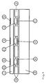
- Figure 1 schematically shows a section of a portion of a control panel in the form of a laminated structure and comprising a decor plate 1 provided with markings, pressure sensitive sensors 4, a compressible layer 2 and a base plate 3.
- the keys are represented by the reference 5. It is possible to provide on the underside of the decor plate one or more windows 7 into which removable strips 8 can be introduced in order to use different texts.
- the reference 9 symbolizes an adhesive between the different layers.
- FIG 2 shows schematically the same structure as that of Figure 1 with the difference that, unlike the embodiment according to Figure 1, the pressure sensitive sensors 4 are located between the compressible elastic layer 2 and the base plate 3.
- FIG. 3 illustrates the possibility of designing the upper surface of the base plate 3 in the form of a plate 6 in which the compressible layer 2 can be housed, the pressure sensors 4 being able to be located, either between the compressible layer 2 and the base plate 3, ie between the compressible layer 2 and the decor plate 1.
- FIG. 4 finally represents a compressible layer 2 provided with notches below the keys 5 of the decoration plate 1 and in which the sensors 4 and of the pressure transmission pads 10 are located. These pads 10 have convex upper and lower faces and allow better transmission of the pressure on the sensors 4.
- FIG. 5 schematically represents a keyboard comprising a grid of sensors 10 of the FSR type sandwiched between two layers 16 and 18 of compressible material, taken, in turn, sandwiched between a rigid base plate 12 and a semi-plate - rigid decoration and protection 14.
- FIG. 6 schematically shows a network of 16 sensors 10 for a control keyboard according to FIG. 5. These 16 sensors are arranged according to a grid or matrix of 4 rows 1, 2, 3, 4 and 4 columns A, B, C, D.
- the first phase consists, for example, in locating first on which of the 4 lines of the grid in FIG. 6 the activated sensor has the most probability of being located.
- electrical identification signals are injected on each of the 4 lines 1 to 4. It therefore takes 4 signals which are represented in FIG. 7 and which are numbered 1 to 4. As this figure shows, these are simple signals with a period T, identical in their configuration, but phase shifted a quarter of the relative to each other. These signals are then collected at the 4 terminals of columns A, B, C, D which, for the needs of the cause can be connected together.
- FIG. 8 represents an example of a signal detected on the terminals A, B, C, D, this signal representing the sum weighted signals 1, 2, 3, 4.
- a threshold S of amplitude which will probably be exceeded by a signal of identification after passing it through an activated sensor.
- this threshold S Only the portion corresponding to signal 3 exceeds this threshold S. Since this portion comes from the signal injected in line 3, it must be concluded that it is in the 3rd line that the most active FSR sensor.
- the second phase consists in determining the column in which the most activated sensor is located. To this end, the procedure for determining the line as described above is carried out in a similar manner. We therefore inject 4 identification signals used in the 4 columns A, B, C, D. These signals are then collected on lines 1, 2, 3, 4, the terminals of which can be connected together for the needs of the cause. Assuming that we collect on the 4 lines the signal shown in Figure 19 we select the portion exceeding the amplitude threshold S. In this case it is the signal injected in column B, which means that the most active sensor is in column B of the grid.
- the key identification mode proposed by the present invention has, in addition to precision, the advantage of being faster than a punctual scan of each of the sensors. Indeed, assuming that we have a keyboard with a grid of m rows and n columns of sensors, it suffices to analyze m + n sensors to locate the most activated sensor while a punctual scan requires the analysis of mxn signals.
- the identification process can be repeated as confirmation.
Abstract
Description
La présente invention concerne un clavier à touches pour panneau de commande comprenant une plaque de base, une plaque de décor pourvue de marquages d'identification de touches auxquelles sont attribuées des fonctions bien précises, ainsi que des capteurs sensibles à une pression d'activation disposée en-dessous de chaque touche entre la plaque de base et la plaque de décor. L'invention concerne également un procédé d'identification d'une touche activée d'un clavier constitué d'une grille de m lignes et n colonnes de touches d'un tel clavier.The present invention relates to a keypad for a control panel comprising a base plate, a decor plate provided with identification markings of keys to which very specific functions are assigned, as well as sensors sensitive to an activation pressure arranged below each key between the base plate and the decor plate. The invention also relates to a method for identifying an activated key of a keyboard consisting of a grid of m lines and n columns of keys of such a keyboard.
Sans y être limitée, l'invention vise notamment des claviers pour des panneaux de commandes destinés à déclencher et superviser des opérations et fonctionnements de toutes sortes de machines, appareils, installations, etc. Un clavier de ce genre est, par exemple, connu par la demande de brevet EP-0 210 386 qui propose un panneau de commandes, de structure stratifiée, comprenant une feuille ou plaque dure formant support avec une couche de couverture entre lesquelles est disposé en sandwich un cristal qui réagit à une pression extérieure par l'émission ou la modification d'un signal électrique.Without being limited thereto, the invention relates in particular to keyboards for control panels intended to trigger and supervise operations and operations of all kinds of machines, apparatus, installations, etc. A keyboard of this kind is, for example, known from patent application EP-0 210 386 which proposes a control panel, of laminated structure, comprising a hard sheet or plate forming a support with a covering layer between which is disposed in sandwich a crystal which reacts to an external pressure by the emission or modification of an electrical signal.
La demande de brevet européen No EP-0 366 832 propose une couverture d'un clavier à touches d'un panneau de commandes qui se présente sous forme d'une plaque rigide déposable sur la surface de manoeuvre du clavier et qui présente aux endroits correspondants aux touches du clavier au moins une zone de transmission de pression qui est souple ou à rigidité réduite.European patent application No. EP-0 366 832 proposes a cover for a keyboard with keys of a control panel which is in the form of a rigid plate which can be deposited on the operating surface of the keyboard and which has in the corresponding places at the keyboard keys at least one pressure transmission zone which is flexible or of reduced rigidity.
Tous ces claviers présentent, suivant leur type d'application, certains inconvénients. C'est ainsi, par exemple, que ces claviers à touches ou panneaux de commande sont sensibles à des influences mécaniques extérieures et peuvent être facilement détériorés par suite de coups ou de mauvais traitements. Il existe, par conséquent, un besoin urgent en claviers à touches ou panneaux de commande qui résistent mieux à des attaques mécaniques extérieures, ne fût-ce qu'à titre de prévention des risques d'actes de vandalisme. Il y a lieu de mentionner aussi que les claviers connus sont relativement sensibles à des vibrations extérieures.All of these keyboards have certain disadvantages, depending on their type of application. Thus, for example, these keyboards with keys or control panels are sensitive to external mechanical influences and can be easily damaged due to blows or ill-treatment. There is, therefore, a need urgent in keypads with keys or control panels which are more resistant to external mechanical attacks, if only to prevent the risk of acts of vandalism. It should also be mentioned that the known keyboards are relatively sensitive to external vibrations.
On connaît, par ailleurs, des capteurs de force du genre décrit dans le brevet US 4,314,228 qui sont maintenant connus sous la marque déposée FSR qui est l'abréviation de "Force Sensing Resistor". Un tel capteur est essentiellement constitué d'une mince pellicule semi-conductrice pouvant être formée par de minuscules particules, par exemple de bisulfure de molybdène d'une taille de l'ordre de 1 à 10 microns noyés dans une résine de support. Une telle pellicule présente une certaine résistance superficielle qui, lorsque la pellicule est appliquée contre une surface conductrice peut être réduite par suite d'une augmentation du nombre de points de contact avec cette surface conductrice sous l'effet d'une pression localisée. Un mode d'exécution avantageux consiste à associer une telle pellicule FSR à une pellicule sur laquelle est déposée un réseau conducteur sous forme de deux peignes d'électrodes en disposition interdigitale. Ces deux pellicules sont scellées l'une à l'autre de façon à ce que les peignes d'électrodes effleurent la surface de la couche semi-conductrice FSR. Lorsqu'aucune force n'est appliquée à un tel FSR, la résistance entre les bornes des peignes d'électrodes est très élevée, généralement de l'ordre de plusieurs mégaohms. Par contre, lorsque le FSR est soumis à une force perpendiculairement à sa surface, la résistance diminue approximativement de façon exponentielle. Cette propriété pourrait être mise à profit dans un clavier en prévoyant, à la place des capteurs électromécaniques habituels des capteurs du type FSR, d'autant plus que, vu la grande sensibilité de ce type de capteurs, il pourrait réagir à une pression locale appliquée à travers une plaque de protection plus ou moins rigide qui serait pourvue à l'extérieur, des marquages d'identification des touches. Malheureusement, des claviers dont les touches seraient associées à des capteurs de force FSR n'ont pas pu être réalisées jusqu'à présent à cause de problèmes d'identification des touches activées. En effet, en utilisant un clavier comprenant une grille ou matrice de capteurs FSR formant les touches de clavier, il suffirait, pour connaître la touche actionnée par un doigt ou un stylet, de déterminer celui de tous les capteurs dont la résistance est la plus faible. Il faudrait donc appliquer successivement un signal électrique à chaque touche et sélectionner, à la sortie, le signal, par exemple avec la plus grande amplitude, qui devrait, en principe, correspondre à la touche activée. On sélectionnerait alors le signal dont l'amplitude dépasse un seuil prédéterminé et qui, de ce fait, devrait correspondre aux capteurs avec la plus faible résistance électrique.We also know force sensors of the kind described in US Pat. No. 4,314,228 which are now known under the registered trademark FSR which is the abbreviation for "Force Sensing Resistor". Such a sensor essentially consists of a thin semiconductor film which can be formed by tiny particles, for example of molybdenum disulphide with a size of the order of 1 to 10 microns embedded in a support resin. Such a film has a certain surface resistance which, when the film is applied against a conductive surface can be reduced as a result of an increase in the number of points of contact with this conductive surface under the effect of localized pressure. An advantageous embodiment consists in associating such an FSR film with a film on which a conductive network is deposited in the form of two combs of electrodes in interdigital arrangement. These two films are sealed to each other so that the electrode combs touch the surface of the FSR semiconductor layer. When no force is applied to such an FSR, the resistance between the terminals of the electrode combs is very high, generally of the order of several megaohms. On the other hand, when the FSR is subjected to a force perpendicular to its surface, the resistance decreases approximately exponentially. This property could be exploited in a keyboard by providing, instead of the usual electromechanical sensors of the FSR type sensors, all the more since, given the great sensitivity of this type of sensor, it could react to a local pressure. applied through a more or less rigid protective plate which would be provided on the outside, identification markings of the keys. Unfortunately, keyboards whose keys would be associated with FSR force sensors could not be produced so far due to problems in identifying the activated keys. Indeed, by using a keyboard comprising a grid or matrix of FSR sensors forming the keyboard keys, it would suffice, to know the key actuated by a finger or a stylus, to determine which of all the sensors whose resistance is the lowest . It would therefore be necessary to successively apply an electrical signal to each key and select, at the output, the signal, for example with the greatest amplitude, which should, in principle, correspond to the activated key. We would then select the signal whose amplitude exceeds a predetermined threshold and which, therefore, should correspond to the sensors with the lowest electrical resistance.
Malheureusement, en procédant de cette manière, on n'est pas du tout certain d'avoir localisé, sans ambiguïté, le capteur correspondant au lieu géométrique de la pression locale la plus faible. Il y a plusieurs raisons à cette incertitude. Lorsqu'une force normale est appliquée à la surface de la plaque de décor d'un tel clavier, celle-ci est distribuée sur la grille des capteurs FSR. En raison de la déflexion locale de la plaque, éventuellement semi-rigide et mécaniquement anisotrope, la pression est localement plus élevée au lieu géométrique de l'application de la force, pour décroître ensuite à mesure qu'on s'éloigne de ce lieu. Cette répartition de la pression sur la grille de capteurs est en outre influencée par une couche d'une matière compressible généralement insérée entre la grille et la plaque de protection qui, elle aussi, est anisotrope et, par conséquent, diffuse la pression de manière irrégulière. Par conséquent, ce n'est pas seulement le capteur correspondant au lieu géométrique de l'application de la pression qui est activé, mais également les capteurs avoisinants suivant leur éloignement de ce lieu.Unfortunately, by proceeding in this way, it is not at all certain to have located, without ambiguity, the sensor corresponding to the geometric location of the lowest local pressure. There are several reasons for this uncertainty. When a normal force is applied to the surface of the decor plate of such a keyboard, it is distributed over the grid of the FSR sensors. Because of the local deflection of the plate, possibly semi-rigid and mechanically anisotropic, the pressure is locally higher at the geometrical place of the application of the force, to decrease then as one moves away from this place. This distribution of the pressure on the sensor grid is further influenced by a layer of compressible material generally inserted between the grid and the protection plate which, too, is anisotropic and, consequently, diffuses the pressure in an irregular manner. . Consequently, it is not only the sensor corresponding to the geometrical place of the application of the pressure which is activated, but also the neighboring sensors according to their distance from this place.
Une seconde raison est que tous les capteurs FSR n'ont pas des propriétés et caractéristiques intrinsèques absolument identiques. Le cumul de ces deux causes rend difficile une identification de la touche correcte en cas de scrutation ponctuelle de toutes les touches comme expliqué ci-dessus.A second reason is that not all FSR sensors have absolutely identical intrinsic properties and characteristics. The combination of these two causes makes it difficult to identify the correct key in the event of punctual scanning of all the keys as explained above.
Le but de la présente invention est de prévoir un nouveau clavier à touches qui présente une meilleure résistance aux influences mécaniques extérieures, ainsi qu'un procédé d'identification d'une touche activée qui est à la fois précis et rapide.The object of the present invention is to provide a new keyboard with keys which has better resistance to external mechanical influences, as well as a method for identifying an activated key which is both precise and rapid.
Pour atteindre cet objectif, la présente invention propose un clavier à touches pour panneaux de commandes du genre décrit dans le préambule qui est caractérisé en ce que les capteurs sont des capteurs de force à résistance variable du type FSR et en ce que la plaque de décor est une plaque semi-rigide.To achieve this objective, the present invention provides a keypad for control panels of the type described in the preamble which is characterized in that the sensors are force sensors with variable resistance of the FSR type and in that the decor plate is a semi-rigid plate.
La structure peut également comporter une couche d'un matériau compressible entre la plaque de base et la plaque de décor. Les capteurs de force sont alors insérés, en-dessous des touches ou des zones de touches, soit entre la plaque de décor et la couche compressible, soit entre celle-ci et la plaque de base.The structure can also include a layer of compressible material between the base plate and the decor plate. The force sensors are then inserted, below the keys or key zones, either between the decoration plate and the compressible layer, or between the latter and the base plate.
La plaque de décor peut présenter un marquage d'une grande finesse, c'est-à-dire de faible distance entre les différentes touches, ce qui permet un grand pouvoir de résolution. Le marquage des touches peut être réalisé sous forme de bandes sans interruption ou d'une autre manière. Il est également possible de prévoir en-dessous de la plaque de décor des rainures permettant d'introduire et de retirer des bandes pourvues des marquages des touches ce qui permet un changement rapide du marquage et de l'identification des touches.The decoration plate may have a marking of great finesse, that is to say of short distance between the different keys, which allows a great power of resolution. The marking of the keys can be carried out in the form of strips without interruption or in another way. It is also possible to provide grooves below the decor plate allowing the insertion and removal of strips provided with the key markings which allows a rapid change of the markings and the identification of the keys.
La plaque de décor du clavier selon la présente invention est étanche aux poussières et à l'eau, et, suivant les besoins, résistante aux agents chimiques et/ou aux actes de vandalisme. Compte tenu des propriétés des capteurs FSR, la force nécessaire à l'activation des touches est réglable. La plaque de décor peut présenter une surface tout à fait lisse et être réalisée en métal en verre ou en matière synthétique selon une présentation et un design conformément aux voeux de l'utilisateur. En dehors d'une durée de vie longue, ces plaques de décor se caractérisent par une faible épaisseur et la possibilité d'une combinaison éventuelle avec des éléments électrooptiques.The keyboard decor plate according to the present invention is dust and water tight, and, as required, resistant to chemical agents and / or acts of vandalism. Given the properties of FSR sensors, the force required to activate the keys is adjustable. The decor plate can have a completely smooth surface and be made of glass metal or synthetic material according to a presentation and a design in accordance with the wishes of the user. Apart from a long lifespan, these decorative plates are characterized by a small thickness and the possibility of a possible combination with electrooptical elements.
Les capteurs réagissent par une résistance variable qui diminue en fonction de la force d'activation des touches. Chaque capteur comporte, de manière connue en soi, une pellicule semi-conductrice laminée à une pellicule avec deux peignes d'électrodes. Lorsqu'une pression est appliquée sur un tel capteur, la couche semi-conductrice shunte plus ou moins les électrodes voisines des deux peignes et réduit la résistance entre ceux-ci.The sensors react by a variable resistance which decreases according to the force of activation of the keys. Each sensor comprises, in a manner known per se, a semiconductor film laminated to a film with two combs of electrodes. When pressure is applied to such a sensor, the semiconductor layer more or less shunts the neighboring electrodes of the two combs and reduces the resistance between them.
L'invention concerne également un procédé d'identification d'une touche activée d'un tel clavier constitué d'une grille de m lignes et n colonnes de touches individuelles, associées chacune à un capteur de force dont la résistance électrique diminue proportionnellement à une force appliquée à sa surface, dans lequel les m x n capteurs sont disposés en sandwich entre une plaque rigide de support et une plaque semi-rigide de protection et de décor portant les marques d'identification des touches, caractérisé en ce que l'on injecte simultanément sur les m bornes des m lignes de capteurs m signaux électriques différents et dissociables entre eux, en ce que l'on recueille sur les bornes des n colonnes les m signaux, en ce que l'on détermine parmi les m signaux le signal i dont le degré de déformation dépasse un seuil prédéterminé et qui correspond à la ligne i dans laquelle se trouve le capteur Cij le plus activé, en ce que l'on injecte simultanément sur les n bornes des n colonnes de capteurs n signaux électriques différents et dissociables entre eux, en ce que l'on recueille sur les bornes des m lignes les n signaux en ce que l'on détermine parmi les n signaux, le signal j dont le degré de déformation dépasse un seuil prédéterminé et qui correspond à la colonne j dans laquelle se trouve le capteur Cij le plus activé.The invention also relates to a method for identifying an activated key of such a keyboard consisting of a grid of m rows and n columns of individual keys, each associated with a force sensor whose electrical resistance decreases in proportion to a force applied to its surface, in which the mxn sensors are sandwiched between a rigid support plate and a semi-rigid protection and decoration plate bearing the identification marks of the keys, characterized in that one simultaneously injects on the m terminals of the m lines of sensors m different electrical signals which can be dissociated from each other, in that the m signals are collected on the terminals of the n columns, in that the signal i whose among i is determined the degree of deformation exceeds a predetermined threshold and which corresponds to the line i in which the most activated sensor C ij is located, in that one injects simultaneously on the n terminals of the n columns of sensors n different and dissociable electrical signals between them, in that one collects on the terminals of the m lines the n signals as determined among the n signals, the signal j whose degree of deformation exceeds a predetermined threshold and which corresponds to the column j in which the sensor C ij is located no longer activated.
A titre de confirmation du résultat d'identification, il est possible de répéter, au moins une fois, toutes les opérations de détermination de la touche Cij.As confirmation of the identification result, it is possible to repeat, at least once, all the operations for determining the key C ij .
Les déformations détectées sur les signaux lors du passage par les capteurs peuvent être la modification de leur amplitude suite au changement de résistance électrique des capteurs. Il est toutefois également possible de détecter d'autres modifications tel que le déphasage ou la fréquence, lorsque les capteurs sont intégrés dans un circuit oscillateur.The deformations detected on the signals during the passage by the sensors can be the modification of their amplitude following the change of electrical resistance of the sensors. It is however also possible to detect other modifications such as phase shift or frequency, when the sensors are integrated in an oscillator circuit.
D'autres particularités et caractéristiques de l'invention ressortiront de la description détaillée de plusieurs modes de réalisation avantageux, présentés ci-dessous, à titre d'illustration, en référence aux dessins annexés dans lesquels:
- les figures 1 à 4 représentent schématiquement des coupes partielles transversales à travers quatres modes d'exécution d'un clavier conformément à la présente invention et dans lesquelles on a utilisé les mêmes chiffres de référence pour désigner les mêmes éléments;
- la figure 5 montre schématiquement une coupe verticale à travers un clavier dont les touches sont constituées par des capteurs FSR;
- la figure 6 montre schématiquement une grille comprenant 4 lignes et 4 colonnes de capteurs;
- la figure 7 montre schématiquement les signaux d'identification destinés à être injectés sur les lignes et les colonnes de la grille de la figure 6;
- la figure 8 représente schématiquement le signal détecté sur les colonnes lorsque les signaux d'identification sont injectés sur les lignes de la grille et
- la figure 9 montre schématiquement le signal détecté sur les lignes de la grille lorsque les signaux d'identification sont injectés sur les colonnes de la grille.
- Figures 1 to 4 schematically show partial cross sections through four modes of execution of a keyboard according to the present invention and in which the same reference numerals have been used to designate the same elements;
- FIG. 5 schematically shows a vertical section through a keyboard, the keys of which are constituted by FSR sensors;
- FIG. 6 schematically shows a grid comprising 4 rows and 4 columns of sensors;
- FIG. 7 schematically shows the identification signals intended to be injected on the rows and columns of the grid of FIG. 6;
- FIG. 8 schematically represents the signal detected on the columns when the identification signals are injected on the grid lines and
- FIG. 9 schematically shows the signal detected on the lines of the grid when the identification signals are injected on the columns of the grid.
La figure 1 montre schématiquement une coupe d'une partie d'un panneau de commande se présentant sous forme d'une structure stratifiée et comprenant une plaque de décor 1 pourvue de marquages, des capteurs 4 sensibles à pression, une couche compressible 2 et une plaque de base 3. Les touches sont représentées par la référence 5. Il est possible de prévoir à la face inférieure de la plaque de décor une ou des fenêtres 7 dans lesquelles peuvent être introduites des bandes amovibles 8 pour pouvoir utiliser des textes différents. La référence 9 symbolise une colle entre les différentes couches.Figure 1 schematically shows a section of a portion of a control panel in the form of a laminated structure and comprising a
La figure 2 représente schématiquement la même structure que celle de la figure 1 avec la différence que, contrairement au mode d'exécution selon la figure 1, les capteurs 4 sensibles à la pression se trouvent entre la couche élastique compressible 2 et la plaque de base 3.Figure 2 shows schematically the same structure as that of Figure 1 with the difference that, unlike the embodiment according to Figure 1, the pressure
La figure 3 illustre la possibilité de concevoir la surface supérieure de la plaque de base 3 en forme d'assiette 6 dans laquelle peut être logée la couche compressible 2, les capteurs de pression 4 pouvant se trouver, soit entre la couche compressible 2 et la plaque de base 3, soit entre la couche compressible 2 et la plaque de décor 1.FIG. 3 illustrates the possibility of designing the upper surface of the
La figure 4 représente finalement une couche compressible 2 pourvue d'encoches en-dessous des touches 5 de la plaque de décor 1 et dans lesquelles se trouvent les capteurs 4 et des pastilles 10 de transmission de pression. Ces pastilles 10 ont des faces supérieures et inférieures convexes et permettent une meilleure transmission de la pression sur les capteurs 4.FIG. 4 finally represents a
Au lieu de réaliser l'assemblage avec de la colle il est possible d'imprimer l'une sur l'autre les différentes couches, y compris les FSR et les pastilles 10, par exemple par un procédé sérigraphique.Instead of making the assembly with glue, it is possible to print the different layers, including the FSR and the
La figure 5 représente schématiquement un clavier comprenant une grille de capteurs 10 du type FSR placée en sandwich entre deux couches 16 et 18 d'un matériau compressible, prises, à leur tour, en sandwich entre une plaque de base rigide 12 et une plaque semi-rigide de décor et de protection 14.FIG. 5 schematically represents a keyboard comprising a grid of
La figure 6 montre schématiquement un réseau de 16 capteurs 10 pour un clavier de commande selon la figure 5. Ces 16 capteurs sont disposés suivant une grille ou matrice de 4 lignes 1, 2, 3, 4 et 4 colonnes A, B, C, D.FIG. 6 schematically shows a network of 16
On va maintenant décrire le procédé d'identification de celui des 16 capteurs FSR qui est activé par une pression ponctuelle localisée. La première phase consiste, par exemple, à localiser d'abord sur laquelle des 4 lignes de la grille de la figure 6 le capteur activé a le plus de probabilité de se trouver. A cet effet, on injecte sur chacune des 4 lignes 1 à 4 des signaux électriques d'identification. Il faut donc 4 signaux qui sont représentés sur la figure 7 et qui sont numérotés 1 à 4. Comme le montre cette figure, il s'agit de simples signaux avec une période T, identiques dans leur configuration, mais déphasés un quart de période les uns par rapport aux autres. Ces signaux sont ensuite recueillis aux 4 bornes des colonnes A, B, C, D qui, pour les besoins de la cause peuvent être connectées entre elles.We will now describe the identification process of that of the 16 FSR sensors which is activated by a localized point pressure. The first phase consists, for example, in locating first on which of the 4 lines of the grid in FIG. 6 the activated sensor has the most probability of being located. To this end, electrical identification signals are injected on each of the 4
La figure 8 représente un exemple d'un signal détecté sur les bornes A, B, C, D, ce signal représentant la somme pondérée des signaux 1, 2, 3, 4. Suivant la nature des capteurs FSR du clavier et suivant l'amplitude des signaux d'identification de la figure 7 on détermine un seuil S d'amplitude qui sera probablement dépassé par un signal d'identification après le passage de celui-ci à travers un capteur activé. Dans l'exemple de la figure 8 seule la portion correspondant au signal 3 dépasse ce seuil S. Etant donné que cette portion est issue du signal injecté dans la ligne 3 il faut en conclure que c'est dans la 3e ligne que se trouve le capteur FSR le plus activé.FIG. 8 represents an example of a signal detected on the terminals A, B, C, D, this signal representing the sum
La seconde phase consiste à déterminer la colonne dans laquelle se trouve le capteur le plus activé. A cet effet on procède d'une manière analogue à la détermination de la ligne telle que décrite ci-dessus. On injecte donc dans les 4 colonnes A, B, C, D 4 signaux d'identification utilisés précédemment. On recueille ensuite ces signaux sur les lignes 1, 2, 3, 4 dont les bornes peuvent être connectées entre elles pour les besoins de la cause. En supposant que l'on recueille sur les 4 lignes le signal représenté sur la figure 19 on sélectionne la portion dépassant le seuil d'amplitude S. En l'occurrence il s'agit du signal injecté dans la colonne B, ce qui signifie que le capteur le plus activé se trouve dans la colonne B de la grille.The second phase consists in determining the column in which the most activated sensor is located. To this end, the procedure for determining the line as described above is carried out in a similar manner. We therefore inject 4 identification signals used in the 4 columns A, B, C, D. These signals are then collected on
Ces deux phases d'identification sont nécessaires et suffisantes pour déterminer, sans ambiguïté, lequel des capteurs de la grille de la figure 6 est activé étant donné que l'on connaît la ligne et la colonne du capteur recherché, en l'occurrence, dans l'exemple représenté dans la ligne No 3 et la colonne B.These two identification phases are necessary and sufficient to determine, without ambiguity, which of the sensors of the grid of FIG. 6 is activated since we know the row and the column of the sensor sought, in this case, in the example shown in
Le mode d'identification des touches proposé par la présente invention a, outre la précision, l'avantage d'être plus rapide qu'une scrutation ponctuelle de chacun des capteurs. En effet, en supposant que l'on ait un clavier avec une grille de m lignes et de n colonnes de capteurs, il suffit d'analyser m + n capteurs pour localiser le capteur le plus activé alors qu'une scrutation ponctuelle nécessite l'analyse de m x n signaux.The key identification mode proposed by the present invention has, in addition to precision, the advantage of being faster than a punctual scan of each of the sensors. Indeed, assuming that we have a keyboard with a grid of m rows and n columns of sensors, it suffices to analyze m + n sensors to locate the most activated sensor while a punctual scan requires the analysis of mxn signals.
Pour être tout à fait certain du résultat de l'identification on peut répéter le procédé d'identification à titre de confirmation.To be completely certain of the identification result, the identification process can be repeated as confirmation.
Au lieu de balayer toutes les lignes et toutes les colonnes en une fois, il est possible, suivant la grandeur du clavier de définir des groupes par ex. m/2', m/₃... etc. de lignes et n/2', n/₃... etc. de colonnes et d'explorer successivement ces groupes pour identifier la touche activée.Instead of scanning all the rows and all the columns at once, it is possible, depending on the size of the keyboard, to define groups, for example. m / 2 ' , m / ₃ ... etc. of lines and n / 2 ' , n / ₃ ... etc. of columns and successively explore these groups to identify the activated key.
Claims (10)
Applications Claiming Priority (4)
| Application Number | Priority Date | Filing Date | Title |
|---|---|---|---|
| DE9016410U DE9016410U1 (en) | 1990-12-03 | 1990-12-03 | |
| DE9016410U | 1990-12-03 | ||
| BE9100157 | 1991-02-18 | ||
| BE9100157A BE1004642A3 (en) | 1991-02-18 | 1991-02-18 | Procedure for identifying a key activated on a keyboard |
Publications (1)
| Publication Number | Publication Date |
|---|---|
| EP0489344A1 true EP0489344A1 (en) | 1992-06-10 |
Family
ID=25662571
Family Applications (1)
| Application Number | Title | Priority Date | Filing Date |
|---|---|---|---|
| EP91120226A Withdrawn EP0489344A1 (en) | 1990-12-03 | 1991-11-27 | Method for identifying an activated key of a keyboard |
Country Status (1)
| Country | Link |
|---|---|
| EP (1) | EP0489344A1 (en) |
Cited By (13)
| Publication number | Priority date | Publication date | Assignee | Title |
|---|---|---|---|---|
| WO1994001935A1 (en) * | 1992-07-13 | 1994-01-20 | Interlink Electronics, Inc. | Adaptive keypad |
| AT397871B (en) * | 1992-03-02 | 1994-07-25 | Hoerbiger Fluidtechnik Gmbh | MEASURING DEVICE |
| EP0617556A1 (en) * | 1993-03-22 | 1994-09-28 | SONY DEUTSCHLAND GmbH | A broadcasting signal receiver |
| FR2707772A1 (en) * | 1993-06-30 | 1995-01-20 | Fusilier Jean Marie | Enhanced flat keypad with progressive return-action keys for the wireless remote control of an operational unit |
| DE4339931C1 (en) * | 1993-11-24 | 1995-03-30 | Daimler Benz Ag | Locator (position sensor, position encoder), in particular for the selector lever of a vehicle gear (transmission, gearbox) |
| WO1996020533A1 (en) * | 1994-12-28 | 1996-07-04 | Screentec Ky | Keyboard |
| EP0901229A2 (en) * | 1997-09-04 | 1999-03-10 | Delco Electronics Europe GmbH | Electrically operable device operation |
| EP1422734A1 (en) * | 2002-11-25 | 2004-05-26 | IEE INTERNATIONAL ELECTRONICS & ENGINEERING S.A. | Data entry device |
| WO2004049364A1 (en) * | 2002-11-25 | 2004-06-10 | Iee International Electronics & Engineering S.A. | Data input device |
| GB2453911A (en) * | 2007-03-26 | 2009-04-29 | Nokia Corp | An input pad having an array of resistive sensing pads disposed under a top surface layer |
| WO2012175369A1 (en) * | 2011-06-23 | 2012-12-27 | Delphi Technologies, Inc. | Control panel comprising a resistive-type backlit key |
| EP2689532B1 (en) * | 2011-03-21 | 2015-01-21 | Delphi Technologies, Inc. | Control panel comprising resistive buttons and spacers |
| CN105518586A (en) * | 2014-08-26 | 2016-04-20 | 深圳纽迪瑞科技开发有限公司 | Discrete pressure sensor and electronic device |
Citations (7)
| Publication number | Priority date | Publication date | Assignee | Title |
|---|---|---|---|---|
| GB2047448A (en) * | 1979-04-16 | 1980-11-26 | Singer Co | Input switch arrangement |
| GB2064873A (en) * | 1979-11-26 | 1981-06-17 | Eventoff Franklin Neal | Pressure sensitive electric switch |
| GB2077508A (en) * | 1980-05-09 | 1981-12-16 | Weatherley Richard | Variable resistance pressure- sensitive laminate |
| US4481815A (en) * | 1982-12-23 | 1984-11-13 | Overton Kenneth J | Tactile sensor |
| GB2163602A (en) * | 1984-08-07 | 1986-02-26 | Casio Computer Co Ltd | Key switch structure |
| GB2191340A (en) * | 1986-05-20 | 1987-12-09 | Amalgamated Wireless Australas | Interchangeable designation for membrane keyboard |
| EP0259894A2 (en) * | 1986-09-12 | 1988-03-16 | Wacom Company, Ltd. | Position detecting apparatus |
-
1991
- 1991-11-27 EP EP91120226A patent/EP0489344A1/en not_active Withdrawn
Patent Citations (7)
| Publication number | Priority date | Publication date | Assignee | Title |
|---|---|---|---|---|
| GB2047448A (en) * | 1979-04-16 | 1980-11-26 | Singer Co | Input switch arrangement |
| GB2064873A (en) * | 1979-11-26 | 1981-06-17 | Eventoff Franklin Neal | Pressure sensitive electric switch |
| GB2077508A (en) * | 1980-05-09 | 1981-12-16 | Weatherley Richard | Variable resistance pressure- sensitive laminate |
| US4481815A (en) * | 1982-12-23 | 1984-11-13 | Overton Kenneth J | Tactile sensor |
| GB2163602A (en) * | 1984-08-07 | 1986-02-26 | Casio Computer Co Ltd | Key switch structure |
| GB2191340A (en) * | 1986-05-20 | 1987-12-09 | Amalgamated Wireless Australas | Interchangeable designation for membrane keyboard |
| EP0259894A2 (en) * | 1986-09-12 | 1988-03-16 | Wacom Company, Ltd. | Position detecting apparatus |
Non-Patent Citations (1)
| Title |
|---|
| MEASUREMENT + CONTROL vol. 18, no. 7, Septembre 1985, LONDRES GB pages 262 - 265; ROBERTSON ET AL: 'tactile sensor system for robotics' * |
Cited By (25)
| Publication number | Priority date | Publication date | Assignee | Title |
|---|---|---|---|---|
| AT397871B (en) * | 1992-03-02 | 1994-07-25 | Hoerbiger Fluidtechnik Gmbh | MEASURING DEVICE |
| WO1994001935A1 (en) * | 1992-07-13 | 1994-01-20 | Interlink Electronics, Inc. | Adaptive keypad |
| US5510783A (en) * | 1992-07-13 | 1996-04-23 | Interlink Electronics, Inc. | Adaptive keypad |
| EP0617556A1 (en) * | 1993-03-22 | 1994-09-28 | SONY DEUTSCHLAND GmbH | A broadcasting signal receiver |
| US5532753A (en) * | 1993-03-22 | 1996-07-02 | Sony Deutschland Gmbh | Remote-controlled on-screen audio/video receiver control apparatus |
| FR2707772A1 (en) * | 1993-06-30 | 1995-01-20 | Fusilier Jean Marie | Enhanced flat keypad with progressive return-action keys for the wireless remote control of an operational unit |
| DE4339931C1 (en) * | 1993-11-24 | 1995-03-30 | Daimler Benz Ag | Locator (position sensor, position encoder), in particular for the selector lever of a vehicle gear (transmission, gearbox) |
| WO1996020533A1 (en) * | 1994-12-28 | 1996-07-04 | Screentec Ky | Keyboard |
| US5917437A (en) * | 1994-12-28 | 1999-06-29 | Screentec Ky | Keyboard |
| EP0901229A2 (en) * | 1997-09-04 | 1999-03-10 | Delco Electronics Europe GmbH | Electrically operable device operation |
| EP0901229A3 (en) * | 1997-09-04 | 1999-04-21 | Delco Electronics Europe GmbH | Electrically operable device operation |
| WO2004049364A1 (en) * | 2002-11-25 | 2004-06-10 | Iee International Electronics & Engineering S.A. | Data input device |
| EP1422734A1 (en) * | 2002-11-25 | 2004-05-26 | IEE INTERNATIONAL ELECTRONICS & ENGINEERING S.A. | Data entry device |
| CN100367427C (en) * | 2002-11-25 | 2008-02-06 | Iee国际电子及工程股份有限公司 | Data input device |
| US7800586B2 (en) | 2002-11-25 | 2010-09-21 | IEE International Elecronics & Engineering S.A. | Data input device |
| GB2453911A (en) * | 2007-03-26 | 2009-04-29 | Nokia Corp | An input pad having an array of resistive sensing pads disposed under a top surface layer |
| EP2689532B1 (en) * | 2011-03-21 | 2015-01-21 | Delphi Technologies, Inc. | Control panel comprising resistive buttons and spacers |
| CN103619637A (en) * | 2011-06-23 | 2014-03-05 | 德尔菲技术公司 | Control panel comprising resistive-type backlit key |
| FR2976867A1 (en) * | 2011-06-23 | 2012-12-28 | Delphi Tech Inc | CONTROL PANEL COMPRISING A RESISTIVE TYPE RETRO-LIKE BUTTON |
| US8926107B2 (en) | 2011-06-23 | 2015-01-06 | Delphi Technologies, Inc. | Control panel including a resistive-type backlit key |
| WO2012175369A1 (en) * | 2011-06-23 | 2012-12-27 | Delphi Technologies, Inc. | Control panel comprising a resistive-type backlit key |
| CN103619637B (en) * | 2011-06-23 | 2016-10-12 | 德尔菲技术公司 | Control panel including resistance type backlight key |
| CN105518586A (en) * | 2014-08-26 | 2016-04-20 | 深圳纽迪瑞科技开发有限公司 | Discrete pressure sensor and electronic device |
| EP3009923A4 (en) * | 2014-08-26 | 2017-03-01 | Shenzhen New Degree Technology Co., Ltd. | Discrete pressure sensor and electronic device |
| CN105518586B (en) * | 2014-08-26 | 2018-08-03 | 深圳纽迪瑞科技开发有限公司 | Discrete pressure inductor and electronic equipment |
Similar Documents
| Publication | Publication Date | Title |
|---|---|---|
| EP0489344A1 (en) | Method for identifying an activated key of a keyboard | |
| EP1614023B8 (en) | Position detection device | |
| EP1116013B1 (en) | Force sensor | |
| FR2697935A1 (en) | Compact and ergonomic communication terminal with proximity detection surfaces. | |
| US20020121145A1 (en) | Fingerprint sensors using membrane switch arrays | |
| FR2562740A1 (en) | CAPACITIVE SWITCH, ASSEMBLY OF SUCH SWITCHES AND COATING FOR THIS SWITCH | |
| EP2321833A1 (en) | Multi-contact tactile sensor including variable-size and -impedance spacing means | |
| WO2002001490A9 (en) | Accurate interactive acoustic plate | |
| WO2008139050A1 (en) | Transparent multi-tactile sensor | |
| WO2008142345A2 (en) | Method for locating a touch on a surface and device for implementing this method | |
| EP0443944A1 (en) | Capacitive type touch screen device | |
| EP1599889A1 (en) | Data input device | |
| FR2617619A1 (en) | Device for mounting an optical touch screen | |
| FR2831707A1 (en) | Touch sensitive surface has pair of films including carbon resistive elements which connects conducting tracks to carbon resistive bands, respectively | |
| EP0016912B1 (en) | Switch set for a keyboard | |
| FR3033423A1 (en) | DISPLAY WITH OPTICAL SHIFTING SYSTEM | |
| EP1131820B1 (en) | Method for reading and writing a data storage medium comprising a material with a succession of material zones having a first and second physical state respectively | |
| FR2662528A1 (en) | Device for locating an object situated in proximity to a detection area and transparent keyboard using the said device | |
| FR2971867A1 (en) | GESTURE CAPACITIVE INTERFACE WITH MEASUREMENT MODE SWITCHING. | |
| EP0203923B1 (en) | Method for scanning a keyboard with capacitive keys and keyboard provided with means for scanning a keyboard according to this method | |
| EP2556354B1 (en) | Pressure sensor device, method for manufacturing such a sensor and use of same for producing a touch-sensitive screen | |
| WO2014183932A1 (en) | Capacitive control interface device and method adapted for the implementation of highly resistive measurement electrodes | |
| WO2002065389A1 (en) | Proximity detection matrix display device | |
| BE1004642A3 (en) | Procedure for identifying a key activated on a keyboard | |
| LU88024A1 (en) | NUMERIC KEYBOARD FOR MANUAL CONTROLS |
Legal Events
| Date | Code | Title | Description |
|---|---|---|---|
| PUAI | Public reference made under article 153(3) epc to a published international application that has entered the european phase |
Free format text: ORIGINAL CODE: 0009012 |
|
| AK | Designated contracting states |
Kind code of ref document: A1 Designated state(s): AT BE CH DE DK ES FR GB GR IT LI LU NL SE |
|
| 17P | Request for examination filed |
Effective date: 19920922 |
|
| 17Q | First examination report despatched |
Effective date: 19950712 |
|
| RAP3 | Party data changed (applicant data changed or rights of an application transferred) |
Owner name: I.E.E. INTERNATIONAL ELECTRONICS & ENGINEERING S.A |
|
| GRAG | Despatch of communication of intention to grant |
Free format text: ORIGINAL CODE: EPIDOS AGRA |
|
| GRAH | Despatch of communication of intention to grant a patent |
Free format text: ORIGINAL CODE: EPIDOS IGRA |
|
| STAA | Information on the status of an ep patent application or granted ep patent |
Free format text: STATUS: THE APPLICATION IS DEEMED TO BE WITHDRAWN |
|
| 18D | Application deemed to be withdrawn |
Effective date: 19960702 |