EP0489619B2 - Private branch exchange - Google Patents
Private branch exchange Download PDFInfo
- Publication number
- EP0489619B2 EP0489619B2 EP91403187A EP91403187A EP0489619B2 EP 0489619 B2 EP0489619 B2 EP 0489619B2 EP 91403187 A EP91403187 A EP 91403187A EP 91403187 A EP91403187 A EP 91403187A EP 0489619 B2 EP0489619 B2 EP 0489619B2
- Authority
- EP
- European Patent Office
- Prior art keywords
- digital
- line
- procedure
- terminal
- isdn
- Prior art date
- Legal status (The legal status is an assumption and is not a legal conclusion. Google has not performed a legal analysis and makes no representation as to the accuracy of the status listed.)
- Expired - Lifetime
Links
Images


Classifications
-
- H—ELECTRICITY
- H04—ELECTRIC COMMUNICATION TECHNIQUE
- H04Q—SELECTING
- H04Q11/00—Selecting arrangements for multiplex systems
- H04Q11/04—Selecting arrangements for multiplex systems for time-division multiplexing
- H04Q11/0428—Integrated services digital network, i.e. systems for transmission of different types of digitised signals, e.g. speech, data, telecentral, television signals
-
- H—ELECTRICITY
- H04—ELECTRIC COMMUNICATION TECHNIQUE
- H04Q—SELECTING
- H04Q3/00—Selecting arrangements
- H04Q3/58—Arrangements providing connection between main exchange and sub-exchange or satellite
- H04Q3/62—Arrangements providing connection between main exchange and sub-exchange or satellite for connecting to private branch exchanges
- H04Q3/625—Arrangements in the private branch exchange
- H04Q3/627—Details
Definitions
- the invention relates to a private branch exchange which can cope with services of the ISDN.
- Document EP-A-0 341 687 is related to a private branch exchange connected to the ISDN.
- the private branch exchange comprises a control unit, in which is formed an incoming information to be received by an extension terminal. This incoming information includes the line accessing number, which is displayed on the extension terminal.
- the invention provides a private branch exchange in accordance with claim 1 and a method for controlling a private branch exchange in accordance with claim 6.
- Another object of the invention is to provide a private branch exchange which calls an extension terminal having the function to execute a communication of the designated kind in the services of the ISDN.
- Still another object of the invention is to provide a private branch exchange which analyzes reception information received from the ISDN and doesn't call a data communication terminal in the case where an information transmission ability of a transmission ability information element relates to a voice.
- Another object of the invention is to provide a private branch exchange which analyzes reception information received from the ISDN and doesn't call a terminal which doesn't have the G3 communicating function in the case where an information transmission ability of a transmission ability information element relates to an audio of 3.1 kHz and high-order layer characteristic identification data of a high-order layer consistency information element relates to G3.
- Another object of the invention is to provide a private branch exchange which analyzes reception information received from the ISDN and doesn't call an extension terminal which doesn't have the data communicating function in the case where an information transmission ability of a transmission ability information element relates to a non-limited digital.
- Another object of the invention is to provide a private branch exchange which calls an extension terminal corresponding to both of a procedure for an analog line and a procedure for a digital line in the case where a call is received from the analog line.
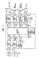
- Fig. 1 is a block diagram showing a system construction of the invention.
- reference numeral 100 denotes a main apparatus of a telephone exchange; 102 an analog telephone network, 104 an ISDN (Integrated service digital network) as a digital public network and 105 an analog line interface which is connected to the analog telephone network 102 through a line 101.
- An exchange method in the embodiment uses a time-sharing method. Therefore, the analog line I/F 105 is connected to an exchange unit 112 through an up PCM highway 106 and a down PCM highway 107.
- Reference numeral 108 denotes an ISDN-T point interface which is connected to the ISDN 104 through a line 103.
- the ISDN-T point interface 108 is connected to the exchange unit 112 though an up PCM highway 109 and a down PCM highway 110.
- Reference numeral 113 denotes an ISDN-S point interface which has the function to enclose ISDN terminals for extensions and encloses a G3/G4 facsimile 190 through a line 129.
- the ISDN-S point interface 113 is connected to the exchange unit 112 through a down PCM highway 114 and an up PCM highway 115.
- Reference numeral 116 denotes a similar ISDN-S point interface to enclose an ISDN telephone 132 through a line 131 in the embodiment.
- the ISDN-S point interface 116 is also connected to the exchange unit 112 through PCM highways 117 and 118.
- Reference numeral 119 denotes a special telephone interface to enclose a special extension telephone 134 only for use in the system through a line 133 for an extension.
- the special telephone interface 119 is connected to the exchange unit 112 through PCM highways 120 and 121.
- the special extension telephone 134 also includes a telephone having the function to connect an SLT (single line telephone: telephone for an analog public network).
- Reference numeral 122 denotes an ordinary telephone interface to enclose a G3 facsimile 135 through a line 135.
- the ordinary telephone interface 122 is connected to the exchange unit 122 through PCM highways 129 and 124.
- a ringer generation unit 127 generates a call signal of 16 Hz and 75 V rme .
- a tone generation unit 111 is connected to the exchange unit 112 through a PCM highway 128 and generates various kinds of service tones to extension terminals.
- Reference numeral 126 denotes a main control unit to control the whole system.
- the main control unit 128 is connected to each of the above interfaces and the exchange unit 112 though a control bus 125.
- Reference numeral 126M denotes a memory in which information which is necessary for the main control unit 126 to control the whole system is stored.
- the information stored in the memory 126M includes information indicating which extension terminal is connected to which extension position and the like.
- Each of the interfaces 113, 116, 119, and 122 can connect a plurality of extension terminals having the same function.
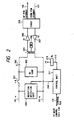
- Fig. 2 is a block diagram of the analog line interface 105 of the embodiment.
- reference numerals 101a and 101b denote lines from the analog telephone network 102.
- Reference numeral 200 denotes a reception detection unit to detect a call reception from the analog telephone network. A detection signal is sent to a control unit 211 through a signal line 209.
- Reference numeral 201 denotes a relay to form a DC loop by a reception response. The relay 201 is driven by the control unit 211 through a signal line 212.
- Reference numeral 202 denotes a DC loop circuit for the response mentioned above and 203 indicates a capacitor to cut a DC current.
- Reference numeral 204 denotes a hybrid transformer to execute a two-wire/four-wire conversion of an AC signal; 205 a receiving amplifier for converting the level of the AC signal from the hybrid transformer 204 and supplying to a codec 208; 207 a transmitting amplifier for converting the level of an AC signal from the codec 208 and supplying to the hybrid transformer 204; and 206 a balancing network serving as a matching circuit to eliminate a leakage of the AC signal from the transmitting amplifier to the receiving amplifier.
- the codec 208 is a circuit to convert the analog signal into the PCM (pulse code modulation) signal and to convert the PCM signal into the analog signal, respectively.
- the codec 208 is connected to the exchange unit 112 through the down PCM highway 107 and the up PCM highway 108.
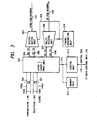
- Fig. 3 is a block diagram of the ISDN-T point interface in the embodiment.
- reference numerals 103a, 103b, 103c, and 103d denote lines from the ISDN 104.
- Reference numeral 302 denotes a processing unit of layers 1 and 2. The processing unit 302 is connected to the lines through transformers 300 and 301.
- Reference numeral 303 denotes a distribution unit to separate and distribute B 1 and B 2 channels from the down PCM highway 110.
- the separated and distributed B 1 channel signal is connected to the layer 1-2 processing unit 302 through a signal line 304.
- the B 2 channel signal is connected to the layer 1-2 processing unit 302 through a signal line 305.
- Reference numeral 306 denotes a multiplexing unit to multiplex the separated B 1 and B 2 channels.
- the B 1 channel signal from the layer 1-2 processing unit 302 is supplied to the multiplexing unit 306 through a signal line 307.
- the B 2 channel signal from the processing unit 302 is supplied to the multiplexing unit 306 through a signal line 308.
- the B 1 and B 2 channel signals are multiplexed by the multiplexing unit 306 and a multiplexed signal is sent to the up PCM highway 109.
- a timing generation unit 310 supplied a timing signal to the distribution unit 303 and the multiplexing unit 306 through a signal line 309.
- a control unit 312 controls the ISDN-T point interface and is connected to the layer 1-2 processing unit 302 and a memory unit 313 through a control line 311 and is also connected to the main control unit 126 through the control bus 125.
- the layer 1-2 processing unit 302 sate a call from the ISDN 104 and transfers to the main control unit 128.
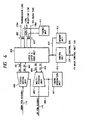
- Fig. 4 is a block diagram of the ISDN-S point interface of the embodiment.
- reference numerals 129a, 129b, 129c, and 129d denote lines which are connected to the G3/G4 facsimile 130.
- Reference numeral 408 denotes a processing unit of the layers 1 and 2. The processing unit 408 is connected to the lines through transformers 409 and 410.
- Reference numeral 400 denotes a distribution unit to separate and distribute the B 1 and B 2 channels from the down PCM highway 114.
- the separated and distributed B 1 channel signal is supplied to the layer 1-2 processing unit 408 through a signal line 401.
- the B 2 channel signal is supplied to the processing unit 408 through a signal line 402.
- Reference numeral 403 denotes a multiplexing unit to multiplex the separated B 1 and B 2 channel signals.
- the B 1 channel signal from the processing unit 408 is supplied to the multiplexing unit 403 through a signal line 404, while the B 2 channel signal is supplied to the multiplexing unit 403 through a signal line 405.
- the B 1 and B 2 channel signals are multiplexed by the multiplexing unit 403 and a multiplexed signal is sent to the up PCM highway 115.
- Reference numeral 407 denotes a timing generation unit to supply a timing signal to the distribution unit 400 and the multiplexing unit 403 through a signal line 406.
- a control unit 413 controls the ISDN-S point interface and is connected to the layer 1-2 processing unit 408 and a memory unit 414 through a control line 412. The control unit 413 is also connected to the main control unit through the control bus 125.
- Reference numeral 411 denotes a power supplying circuit unit (feeder unit) to supply a power source to the G3/G4 facsimile 130.
- step S500 the kind of line is discriminated in step S501.
- step S502 When the kind of line indicates the call reception from the PSTN 102, step S502 follows.
- step S513 follows.
- the call reception from the PSTN 102 is detected by the reception detection unit 200 in Fig. 2 and a detection signal is sent to the control unit 211 through the signal line 209.
- the detection signal is subsequently transmitted to the main control unit 126 through the control bus 125, so that the call reception from the PSTN 102 is detected by the main control unit 126.
- a detection signal of the call reception from the ISDN 104 is transmitted through the reception lines 103c and 103d in Fig. 3 and is sent from the layer 1-2 processing unit 302 to the control unit 312 through the signal line 311.
- the D channel information indicative of such a reception is transmitted to the main control unit 126 through the control bus 125, so that the call reception from the ISDN 104 is detected by the main control unit 126.
- step S502 When a call from the PSTN 102 is received, a check is first made in step S502 to see if a calling process to the ring assignment extension has been finished or not. When the calling process is not finished yet, the main control unit 126 searches the ring assignment extension in step S503. The process is branched in step S504 in accordance with the kind of extension.
- step S506 the main control unit 126 discriminates whether such as extension is a G4 facsimile or not by referring to the memory 128M in step S505. If YES, step S506 follows. If NO, step S507 follows to execute a ringing process.
- step S506 the main control unit 126 discriminates whether such a G4 facsimile has the G3 function or not by referring to the memory 126M. If YES, step S507 follows. If NO, the ringing process is not performed and the processing routine is returned to step S502 to search the next ring assignment extension.
- the main control unit 126 requests a call setting through the ISDN-S point interfaces 113 and 116 to the terminals 130 and 132 connected to the S point in step S507 and waits for a call set acceptance display from the terminals 130 and 132.
- a check is made in step S509 to see if there are call notifications from the terminals 130 and 132 or not.
- the processing routine is returned to step S502.
- step S510 a ringing tone is selected from the tone generation unit 111 shown in Fig. 1 and is connected to the ring assignment special telephone through the exchange unit 112.
- step S511 a speaker of the special telephone is turned on.
- step S512 a state indicative of the in-reception is displayed. For instance, when the special telephone has a display such as an LCD (liquid crystal display) or the like, the in-reception is displayed by the LCD.
- the special telephone has an LED (light emitting diode) or the like in correspondence to an external line button or the like, the LED is allowed to flicker or the like.
- step S504 when the ring assignment extension is an SLT (two-wire telephone) or a G3 facsimile, the ringer generation unit 127 in Fig. 1 is turned on in step S513 and an IR (call) signal is sent to the terminal. The processing routine is returned to step S502.
- SLT two-wire telephone
- IR call
- step S502 a check is made to see if all of the extensions to be allowed to ring have been searched or not. If YES, the processing routine advances to an "incalling" state and the apparatus waits for a response from the extension. If NO, the processes are repeated from step S503.
- the main control unit 126 When the main control unit 126 detects that the extension such as a G3/G4 facsimile 130 has responded through the ISDN-5 point interface 118, the main control unit controls the exchange unit 112 so as to connect the external line 101 which has received and the extension 130 which has responded.
- the main control unit 126 recognizes the generation of such a request through the ISDN-S point interface 113 and controls the analog line interface 105 in accordance with dial information from the G3/G4 facsimile 130, thereby performing a call generation.
- the main control unit 126 controls the exchange unit 112 so as to connect the G3/G4 facsimile 130 with the external line which has generated the call in the PSTN 102.
- step S515 when the main control unit 126 detects the call reception by the ISDN-T point interface 108, in step S515, the received call set (set-up) information is stored into the memory 126M and a transmission ability information element in the call set information is extracted, in step S516, the process is branched by referring to the information transfer ability included in such information.
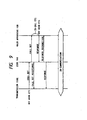
- Fig. 9 shows a schematic sequence of the call reception from the ISDN 104.
- the ISDN 104 When the transmission user executes the off-hook or the like and sends a call set message to the ISDN 104, the ISDN 104 transmite the call set message to the main apparatus 100.
- the ISDN 104 also sends a call set acceptance message to the transmission user in order to transmit the information indicating that the call set from the transmission user has been received.
- the main control unit 126 of the main apparatus 100 receives the call set and recognizes the reception call and executes a calling process and the like in step S516 and subsequent steps.
- the main control unit 126 detects the operation such as an off-hook or the like and transmits a response message to the ISDN 104.
- the ISDN 104 transmits a response recognition message to the main apparatus 100 and transmits a response message to the transmission user.
- the kinds of communication are shown in the transmisison ability information elements.
- the kinds of communication services are further finely specified in the optional high-order layer consistency information elements.
- Fig. 10 shows information formats when messages of a call generation, a reception call, a response, etc. in the ISDN are transmitted.
- the case of the call set message is shown as an example in Fig. 10.
- Reference numeral 20 denotes protocol identification data; 21 a call number; 22 a kind of message in which the value indicative of the call set is set; and 23 to 27 blocks in which necessary information can be added every message kind.
- the kind of information element is set into a head octet in each block.
- the transmission ability in the block 23 specifies the information transfer ability or the like of a voice, 3,1 kHz audio, and non-limited digital.
- the channel identification data in the block 24 specifies the interface type (fundamental or primary group) or specifies whether a change in channel of the fundamental interface is permitted or not.
- the reception number in the block 25 designates a communication partner and the telephone number of the reception user is set.
- the network is transparently transmitted to the high-order layer consistency in the block 26.
- the high-order layer consistency specifies the kind of communication service such as telephone, G2/G3, G4, teletex, or the like.
- the low-order layer consistency in the block 27 specifies an information transfer speed, each format (e.g., stop bit, parity) upon data communication, and the like.
- step S600 the main control unit 126 first checks to see if a calling process to the ring assignment extensions has been finished or not. If NO, the ring assignment extensions registered in the memory 126M are searched in step S601. The kinds of ring assignment extensions registered in the memory 126M are discriminated in step S602 and the processing routine is branched.
- step S603 When the main control unit 126 determines that the extension is an S-point telephone by referring to the memory 126M, a check is further made in step S603 to see if the extension is a G4 facsimile or not by referring to the memory 126M. When It is the G4 facsimile, the processing routine is returned to step S600 without executing the calling process. When it is not the G4 facsimile, the main control unit 126 sends a call set request to the S-point telephone in step S604 and waits for the call set acceptance display from the S-point telephone.
- the call set acceptance display is sent to a T point, namely, the external line 103 which has received the call by the ISDN-T point interface 108 in step S806.
- a call request display is sent to the external line 103 in step S808.
- the call set acceptance display is sent to the T point, namely, the external line 103 in step S609.
- the call request display is transmitted in step S610.
- the processes in steps S609 and S610 are omitted so long as they have already been executed at least once by another route.
- a ringing tone is selected from the tone generation unit 111 shown in Fig. 1 in step S611.
- the ringing tone is connected to the ring assignment special telephone through the exchange unit 112.
- the speaker of the special telephone 134 is turned on in step S612.
- the in-reception display is executed in step S613 in a manner similar to step S512.
- step S602 When the ring assignment extension is an SLT or G3 facsimile in step S602, the call set acceptance display and the call request display are executed to the T point, namely, the external line 103 in steps S614 and S615. The processes in steps S614 and S615 are omitted so long as they have already been executed at least once by another route.
- step S616 the ringer generation unit 127 in Fig. 1 is turned on and the IR signal is sent to the terminal. The calling process is finished.
- the main control unit 128 discriminates whether the calling process has been finished or not in step S700. If NO, the ring assignment extension registered in the memory 126M is extracted in stop S701.
- the main control unit 126 discriminates the kind of ring assignment extension by referring to the memory 126M in step S702.
- a check is made in step S703 to see if the high-order layer characteristic identification data indicates the G3 facsimile or not by referring to the high-order layer constency information element which has been received from the external line 104 and stored in the memory 126M.
- step S704 follows.
- step S705 follows.
- step S704 the main control unit 126 discriminates whether the S-point telephone terminal extracted in step S702 is the G3/G4 facsimile having the G3 function or not by referring to the memory 126M. When it is the G3/G4 facsimile, step S705 follows. If NO, the processing routine is returned to step S700.
- the terminal When the terminal is the G3/G4 facsimile which doesn't have the G3 function or the ISDN telephone having only the telephone function, the reception to the terminal registered in the memory 128M is inhibited. Therefore, it is possible to prevent that the call is received to the terminal which has been designated from the ISDN 104 and cannot perform the communication and a communicating efficiency deteriorates.
- step S705 the call set request is sent to the S-point telephone and a check is made to see if the call set acceptance display is generated from the S-point telephone or not.
- the main control unit 126 recognizes the call set acceptance display from the terminal.
- step S706 the call set acceptance display is sent to the T point, namely, the external line 103 to which a reception call is performed by the ISDN-T point interface 108 in step S707.
- step S708 the cell request display is sent to the external line 103 in step S709.
- the processes in steps S707 and S709 are omitted so long as they have already been executed at least once by another route.
- step S710 follows.
- the processes in steps S710 to S714 are similar to those in steps S609 to S613.
- step S715 follows.
- the processes in steps S715 to S717 are similar to those in steps S614 to S616.
- the main control unit 126 executes the processes shown in Fig. 8.
- the main control unit 126 checks to see if the calling process has been finished or not in step S800. If NO, the ring assignment extension registered in the memory 126M is extracted in step S801.
- step S802 When the main control unit 126 determines in step S802 that the ring assignment extension extracted in step S801 is the S-point telephone by referring to the memory 126M, a check is now made in step S803 that the high-order layer characteristic discrimination data indicates the G4 facsimile or not by referring to the high-order layer consistency information element which has been received from the external line and stored in the memory 126M. If YES, step S804 follows. If NO, or when such an information element is not transmitted, step S805 follows.
- step S804 the main control unit 126 discriminates whether the S-point telephone terminal extracted in step S801 is the G4 facsimile (including the G4 facsimile having the G3 function) or not by referring to the memory 128M. If YES, step S806 follows. In step S805, the main control unit 126 checks to see if the S-point telephone terminal is a terminal which can handle only the voice or not by referring to the memory 128M. If yes, the processing routine is returned to step S800 without executing the calling process.
- step S806 the call set request is sent to the S-point telephone and the apparatus waits for the generation of the call set acceptance display from the S-point telephone.
- the call set acceptance display is sent to the T point, namely, the external line 103 to which a reception call is performed by the ISDN-T point interface 108 in step S808.
- the call request display is sent to the external line 103 in step S810.
- step S811 When it is decided in step S802 that the ring assignment extension is a special telephone, step S811 follows. The processes in steps S811 to S815 are similar to those in steps S609 to S613.
- step S802 When the ring assignment extension is the SLT or G3 facsimile in step S802, the processing routine is returned to step S800 without executing the processes.
- the invention can be also applied to the computer communication. That is, although the embodiment has been described with respect to the G3 and G4 facsimile apparatuses, the invention can be also applied to the analog computer communication and the digital computer communication.
Description
- The invention relates to a private branch exchange which can cope with services of the ISDN.
- A private branch exchange is known from document "Sonderausgabe belcom report und Siemens-Magazin COM", entitled "ISDN im Büro-Hicom - Anwendernutzen und Technik des ISDN-Kommunikationssystems HICOM", from Siemens Aktiengesellschaft, Berlin and Munich. 1985. ISBN 3-8009-3846-4.
- According to a conventional private branch exchange, when a call is received from an ISDN line, all of digital terminals which have been preset in correspondence to the line are allowed to ring. When a call is received from an analog line, all of analog terminals which have been preset in correspondence to the line are allowed to ring.
- In the conventional private branch exchange, therefore, even when a transmission terminal notifies information indicating that it wants to execute a communication as a telephone through the ISDN, not only the digital telephones but also the G4 facsimiles are allowed to ring. Consequent when the G4 facsimile responds to a call reception, the communication cannot be performed.
- On the other hand, in the conventional private branch exchange, even when a transmission terminal notifies information indicating that it wants to perform a data communication through the ISDN, not only the G4 facsimiles but also the digital telephones which can perform only the communication are allowed to ring. Therefore, when such a digital telephone responds to a call reception, the data communication cannot be performed.
- In the conventional private exchange, when a G3/G4 facsimile having both of the G3 and G4 functions is connected to an extension digital interface, in the case where a call is received from the G3 facsimile through the analog line, the G3/G4 facsimile cannot be allowed to respond to the call reception.
- Document EP-A-0 341 687 is related to a private branch exchange connected to the ISDN. The private branch exchange comprises a control unit, in which is formed an incoming information to be received by an extension terminal. This incoming information includes the line accessing number, which is displayed on the extension terminal.
- The invention provides a private branch exchange in accordance with
claim 1 and a method for controlling a private branch exchange in accordance with claim 6. - It is an object of the invention to improve a private branch exchange which can cope with services of the ISDN.
- Another object of the invention is to provide a private branch exchange which calls an extension terminal having the function to execute a communication of the designated kind in the services of the ISDN.
- Still another object of the invention is to provide a private branch exchange which analyzes reception information received from the ISDN and doesn't call a data communication terminal in the case where an information transmission ability of a transmission ability information element relates to a voice.
- Further another object of the invention is to provide a private branch exchange which analyzes reception information received from the ISDN and doesn't call a terminal which doesn't have the G3 communicating function in the case where an information transmission ability of a transmission ability information element relates to an audio of 3.1 kHz and high-order layer characteristic identification data of a high-order layer consistency information element relates to G3.
- Further another object of the invention is to provide a private branch exchange which analyzes reception information received from the ISDN and doesn't call an extension terminal which doesn't have the data communicating function in the case where an information transmission ability of a transmission ability information element relates to a non-limited digital.
- Further another object of the invention is to provide a private branch exchange which calls an extension terminal corresponding to both of a procedure for an analog line and a procedure for a digital line in the case where a call is received from the analog line.
- The above and other objects and features of the present invention will become apparent from the following detailed description and the appended claims with reference to the accompanying drawings.
-
- Fig. 1 is a block diagram of an apparatus embodying the invention:
- Fig. 2 is a block diagram of an analog line interface of the apparatus embodying the invention;
- Fig. 3 is a block diagram of an ISDN-T point interface of the apparatus embodying the invention:
- Fig. 4 is a block diagram of an ISDN-S point interface of the apparatus embodying the invention;
- Figs. 5 to 8 are flowcharts for embodying the invention;
- Fig. 9 is a communication schematic sequence of the ISDN; and
- Fig. 10 shows an information format of messages of the ISDN.
- Fig. 1 is a block diagram showing a system construction of the invention. In the diagram, reference numeral 100 denotes a main apparatus of a telephone exchange; 102 an analog telephone network, 104 an ISDN (Integrated service digital network) as a digital public network and 105 an analog line interface which is connected to the
analog telephone network 102 through aline 101. An exchange method in the embodiment uses a time-sharing method. Therefore, the analog line I/F 105 is connected to anexchange unit 112 through an up PCMhighway 106 and a down PCMhighway 107.Reference numeral 108 denotes an ISDN-T point interface which is connected to the ISDN 104 through aline 103. - The ISDN-
T point interface 108 is connected to theexchange unit 112 though an up PCMhighway 109 and a down PCMhighway 110. -
Reference numeral 113 denotes an ISDN-S point interface which has the function to enclose ISDN terminals for extensions and encloses a G3/G4 facsimile 190 through aline 129. The ISDN-S point interface 113 is connected to theexchange unit 112 through a down PCMhighway 114 and an up PCMhighway 115.Reference numeral 116 denotes a similar ISDN-S point interface to enclose an ISDNtelephone 132 through aline 131 in the embodiment. The ISDN-S point interface 116 is also connected to theexchange unit 112 through PCMhighways - Reference numeral 119 denotes a special telephone interface to enclose a
special extension telephone 134 only for use in the system through aline 133 for an extension. The special telephone interface 119 is connected to theexchange unit 112 through PCMhighways special extension telephone 134 also includes a telephone having the function to connect an SLT (single line telephone: telephone for an analog public network). -
Reference numeral 122 denotes an ordinary telephone interface to enclose aG3 facsimile 135 through aline 135. Theordinary telephone interface 122 is connected to theexchange unit 122 through PCMhighways ringer generation unit 127 generates a call signal of 16 Hz and 75 Vrme. A tone generation unit 111 is connected to theexchange unit 112 through a PCMhighway 128 and generates various kinds of service tones to extension terminals. -
Reference numeral 126 denotes a main control unit to control the whole system. Themain control unit 128 is connected to each of the above interfaces and theexchange unit 112 though acontrol bus 125. Reference numeral 126M denotes a memory in which information which is necessary for themain control unit 126 to control the whole system is stored. The information stored in the memory 126M includes information indicating which extension terminal is connected to which extension position and the like. - Each of the
interfaces - Fig. 2 is a block diagram of the
analog line interface 105 of the embodiment. In the diagram, reference numerals 101a and 101b denote lines from theanalog telephone network 102.Reference numeral 200 denotes a reception detection unit to detect a call reception from the analog telephone network. A detection signal is sent to acontrol unit 211 through asignal line 209.Reference numeral 201 denotes a relay to form a DC loop by a reception response. Therelay 201 is driven by thecontrol unit 211 through asignal line 212.Reference numeral 202 denotes a DC loop circuit for the response mentioned above and 203 indicates a capacitor to cut a DC current. -
Reference numeral 204 denotes a hybrid transformer to execute a two-wire/four-wire conversion of an AC signal; 205 a receiving amplifier for converting the level of the AC signal from thehybrid transformer 204 and supplying to acodec 208; 207 a transmitting amplifier for converting the level of an AC signal from thecodec 208 and supplying to thehybrid transformer 204; and 206 a balancing network serving as a matching circuit to eliminate a leakage of the AC signal from the transmitting amplifier to the receiving amplifier. Thecodec 208 is a circuit to convert the analog signal into the PCM (pulse code modulation) signal and to convert the PCM signal into the analog signal, respectively. Thecodec 208 is connected to theexchange unit 112 through the down PCMhighway 107 and the up PCMhighway 108. - Fig. 3 is a block diagram of the ISDN-T point interface in the embodiment. In the diagram,
reference numerals ISDN 104.Reference numeral 302 denotes a processing unit oflayers processing unit 302 is connected to the lines throughtransformers -
Reference numeral 303 denotes a distribution unit to separate and distribute B1 and B2 channels from thedown PCM highway 110. The separated and distributed B1 channel signal is connected to the layer 1-2processing unit 302 through asignal line 304. The B2 channel signal is connected to the layer 1-2processing unit 302 through asignal line 305. -
Reference numeral 306 denotes a multiplexing unit to multiplex the separated B1 and B2 channels. The B1 channel signal from the layer 1-2processing unit 302 is supplied to themultiplexing unit 306 through asignal line 307. The B2 channel signal from theprocessing unit 302 is supplied to themultiplexing unit 306 through asignal line 308. The B1 and B2 channel signals are multiplexed by themultiplexing unit 306 and a multiplexed signal is sent to the upPCM highway 109. Atiming generation unit 310 supplied a timing signal to thedistribution unit 303 and themultiplexing unit 306 through asignal line 309. - A
control unit 312 controls the ISDN-T point interface and is connected to the layer 1-2processing unit 302 and amemory unit 313 through acontrol line 311 and is also connected to themain control unit 126 through thecontrol bus 125. - The layer 1-2
processing unit 302 sate a call from theISDN 104 and transfers to themain control unit 128. - Fig. 4 is a block diagram of the ISDN-S point interface of the embodiment. In the diagram,
reference numerals G4 facsimile 130.Reference numeral 408 denotes a processing unit of thelayers processing unit 408 is connected to the lines throughtransformers -
Reference numeral 400 denotes a distribution unit to separate and distribute the B1 and B2 channels from thedown PCM highway 114. The separated and distributed B1 channel signal is supplied to the layer 1-2processing unit 408 through asignal line 401. The B2 channel signal is supplied to theprocessing unit 408 through asignal line 402.Reference numeral 403 denotes a multiplexing unit to multiplex the separated B1 and B2 channel signals. The B1 channel signal from theprocessing unit 408 is supplied to themultiplexing unit 403 through asignal line 404, while the B2 channel signal is supplied to themultiplexing unit 403 through asignal line 405. The B1 and B2 channel signals are multiplexed by themultiplexing unit 403 and a multiplexed signal is sent to the upPCM highway 115.Reference numeral 407 denotes a timing generation unit to supply a timing signal to thedistribution unit 400 and themultiplexing unit 403 through asignal line 406. - A
control unit 413 controls the ISDN-S point interface and is connected to the layer 1-2processing unit 408 and amemory unit 414 through acontrol line 412. Thecontrol unit 413 is also connected to the main control unit through thecontrol bus 125. -
Reference numeral 411 denotes a power supplying circuit unit (feeder unit) to supply a power source to the G3/G4 facsimile 130. - The operation of the
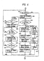
main control unit 125 will now be described in accordance with a flowchart shown in Fig. 5. - When the
main control unit 126 detects the call reception. In step S500, the kind of line is discriminated in step S501. When the kind of line indicates the call reception from thePSTN 102, step S502 follows. When it indicates the call reception from theISDN 104, step S513 follows. - The call reception from the
PSTN 102 is detected by thereception detection unit 200 in Fig. 2 and a detection signal is sent to thecontrol unit 211 through thesignal line 209. The detection signal is subsequently transmitted to themain control unit 126 through thecontrol bus 125, so that the call reception from thePSTN 102 is detected by themain control unit 126. - On the other hand, a detection signal of the call reception from the
ISDN 104 is transmitted through the reception lines 103c and 103d in Fig. 3 and is sent from the layer 1-2processing unit 302 to thecontrol unit 312 through thesignal line 311. The D channel information indicative of such a reception is transmitted to themain control unit 126 through thecontrol bus 125, so that the call reception from theISDN 104 is detected by themain control unit 126. - When a call from the
PSTN 102 is received, a check is first made in step S502 to see if a calling process to the ring assignment extension has been finished or not. When the calling process is not finished yet, themain control unit 126 searches the ring assignment extension in step S503. The process is branched in step S504 in accordance with the kind of extension. - In the case where information indicating that the kind of ring assignment extension indicates the S point telephone has already been registered in the memory 126M, the
main control unit 126 discriminates whether such as extension is a G4 facsimile or not by referring to the memory 128M in step S505. If YES, step S506 follows. If NO, step S507 follows to execute a ringing process. - In step S506, the
main control unit 126 discriminates whether such a G4 facsimile has the G3 function or not by referring to the memory 126M. If YES, step S507 follows. If NO, the ringing process is not performed and the processing routine is returned to step S502 to search the next ring assignment extension. - The
main control unit 126 requests a call setting through the ISDN-S point interfaces 113 and 116 to theterminals terminals terminals - In the case where the kind of ring assignment extension has been registered as a special telephone in the memory 128M in step S504, the
main control unit 128 progresses the processing routine to step S510. In step S510, a ringing tone is selected from the tone generation unit 111 shown in Fig. 1 and is connected to the ring assignment special telephone through theexchange unit 112. In step S511, a speaker of the special telephone is turned on. In step S512, a state indicative of the in-reception is displayed. For instance, when the special telephone has a display such as an LCD (liquid crystal display) or the like, the in-reception is displayed by the LCD. When the special telephone has an LED (light emitting diode) or the like in correspondence to an external line button or the like, the LED is allowed to flicker or the like. - In step S504, when the ring assignment extension is an SLT (two-wire telephone) or a G3 facsimile, the
ringer generation unit 127 in Fig. 1 is turned on in step S513 and an IR (call) signal is sent to the terminal. The processing routine is returned to step S502. - In step S502, a check is made to see if all of the extensions to be allowed to ring have been searched or not. If YES, the processing routine advances to an "incalling" state and the apparatus waits for a response from the extension. If NO, the processes are repeated from step S503.
- In the case of ringing one extension such as in the case of a DIL (direct inline) or the like, the processes are also similarly executed.
- When the
main control unit 126 detects that the extension such as a G3/G4 facsimile 130 has responded through the ISDN-5point interface 118, the main control unit controls theexchange unit 112 so as to connect theexternal line 101 which has received and theextension 130 which has responded. - On the contrary, in the case where there is a request for the G3 transmission from the G3/
G4 facsimile 130 through thePSTN 102, themain control unit 126 recognizes the generation of such a request through the ISDN-S point interface 113 and controls theanalog line interface 105 in accordance with dial information from the G3/G4 facsimile 130, thereby performing a call generation. Themain control unit 126 controls theexchange unit 112 so as to connect the G3/G4 facsimile 130 with the external line which has generated the call in thePSTN 102. - On the other hand, when the
main control unit 126 detects the call reception by the ISDN-T point interface 108, in step S515, the received call set (set-up) information is stored into the memory 126M and a transmission ability information element in the call set information is extracted, in step S516, the process is branched by referring to the information transfer ability included in such information. - Fig. 9 shows a schematic sequence of the call reception from the
ISDN 104. - When the transmission user executes the off-hook or the like and sends a call set message to the
ISDN 104, theISDN 104 transmite the call set message to the main apparatus 100. TheISDN 104 also sends a call set acceptance message to the transmission user in order to transmit the information indicating that the call set from the transmission user has been received. - The
main control unit 126 of the main apparatus 100 receives the call set and recognizes the reception call and executes a calling process and the like in step S516 and subsequent steps. Themain control unit 126 detects the operation such as an off-hook or the like and transmits a response message to theISDN 104. TheISDN 104 transmits a response recognition message to the main apparatus 100 and transmits a response message to the transmission user. - For the reception of the
ISDN 104, that is, the call set message, as shown in Fig. 10, the kinds of communication are shown in the transmisison ability information elements. The kinds of communication services are further finely specified in the optional high-order layer consistency information elements. - Fig. 10 shows information formats when messages of a call generation, a reception call, a response, etc. in the ISDN are transmitted. The case of the call set message is shown as an example in Fig. 10.
-
Reference numeral 20 denotes protocol identification data; 21 a call number; 22 a kind of message in which the value indicative of the call set is set; and 23 to 27 blocks in which necessary information can be added every message kind. The kind of information element is set into a head octet in each block. - The transmission ability in the
block 23 specifies the information transfer ability or the like of a voice, 3,1 kHz audio, and non-limited digital. The channel identification data in theblock 24 specifies the interface type (fundamental or primary group) or specifies whether a change in channel of the fundamental interface is permitted or not. - The reception number in the
block 25 designates a communication partner and the telephone number of the reception user is set. The network is transparently transmitted to the high-order layer consistency in theblock 26. The high-order layer consistency specifies the kind of communication service such as telephone, G2/G3, G4, teletex, or the like. The low-order layer consistency in theblock 27 specifies an information transfer speed, each format (e.g., stop bit, parity) upon data communication, and the like. - The case where the information transfer ability relates to the speech will now be described with reference to a flowchart of Fig. 6.
- In step S600, the
main control unit 126 first checks to see if a calling process to the ring assignment extensions has been finished or not. If NO, the ring assignment extensions registered in the memory 126M are searched in step S601. The kinds of ring assignment extensions registered in the memory 126M are discriminated in step S602 and the processing routine is branched. - When the
main control unit 126 determines that the extension is an S-point telephone by referring to the memory 126M, a check is further made in step S603 to see if the extension is a G4 facsimile or not by referring to the memory 126M. When It is the G4 facsimile, the processing routine is returned to step S600 without executing the calling process. When it is not the G4 facsimile, themain control unit 126 sends a call set request to the S-point telephone in step S604 and waits for the call set acceptance display from the S-point telephone. When themain control unit 126 recognizes the call set acceptance display from the terminal in step S605, the call set acceptance display is sent to a T point, namely, theexternal line 103 which has received the call by the ISDN-T point interface 108 in step S806. When the call notification from the S-point telephone is subsequently recognized in step S607, a call request display is sent to theexternal line 103 in step S808. The processes in steps S808 and S808 are omitted so long as they have already been executed at least once by another route. - When the ring assignment extension is the
special telephone 134 in step S602, the call set acceptance display is sent to the T point, namely, theexternal line 103 in step S609. The call request display is transmitted in step S610. The processes in steps S609 and S610 are omitted so long as they have already been executed at least once by another route. - A ringing tone is selected from the tone generation unit 111 shown in Fig. 1 in step S611. The ringing tone is connected to the ring assignment special telephone through the
exchange unit 112. The speaker of thespecial telephone 134 is turned on in step S612. The in-reception display is executed in step S613 in a manner similar to step S512. - When the ring assignment extension is an SLT or G3 facsimile in step S602, the call set acceptance display and the call request display are executed to the T point, namely, the
external line 103 in steps S614 and S615. The processes in steps S614 and S615 are omitted so long as they have already been executed at least once by another route. In step S616, theringer generation unit 127 in Fig. 1 is turned on and the IR signal is sent to the terminal. The calling process is finished. - On the other hand, when the information transfer ability indicates 3.1 kHz audio in step S516 in Fig. 5, the
main control unit 126 executes the processes shown in Fig. 7. - The
main control unit 128 discriminates whether the calling process has been finished or not in step S700. If NO, the ring assignment extension registered in the memory 126M is extracted in stop S701. - The
main control unit 126 discriminates the kind of ring assignment extension by referring to the memory 126M in step S702. When the ring assignment extension extracted in step S701 indicates the S-point telephone, a check is made in step S703 to see if the high-order layer characteristic identification data indicates the G3 facsimile or not by referring to the high-order layer constency information element which has been received from theexternal line 104 and stored in the memory 126M. When it is the G3 facsimile, step S704 follows. When it is not the G3 facsimile or when such information element is not transmitted, step S705 follows. - In step S704, the
main control unit 126 discriminates whether the S-point telephone terminal extracted in step S702 is the G3/G4 facsimile having the G3 function or not by referring to the memory 126M. When it is the G3/G4 facsimile, step S705 follows. If NO, the processing routine is returned to step S700. - When the terminal is the G3/G4 facsimile which doesn't have the G3 function or the ISDN telephone having only the telephone function, the reception to the terminal registered in the memory 128M is inhibited. Therefore, it is possible to prevent that the call is received to the terminal which has been designated from the
ISDN 104 and cannot perform the communication and a communicating efficiency deteriorates. - In step S705, the call set request is sent to the S-point telephone and a check is made to see if the call set acceptance display is generated from the S-point telephone or not. When the
main control unit 126 recognizes the call set acceptance display from the terminal. In step S706, the call set acceptance display is sent to the T point, namely, theexternal line 103 to which a reception call is performed by the ISDN-T point interface 108 in step S707. Subsequently, when the call notification from the S-point telephone is recognized in step S708, the cell request display is sent to theexternal line 103 in step S709. The processes in steps S707 and S709 are omitted so long as they have already been executed at least once by another route. - When the ring assignment extension is the
special telephone 134 in step S702, step S710 follows. The processes in steps S710 to S714 are similar to those in steps S609 to S613. - When the ring assignment extension is the SLT or G3 facsimile in step S702, step S715 follows. The processes in steps S715 to S717 are similar to those in steps S614 to S616.
- When the information transfer ability indicates the non-limited digital in step S516 in Fig. 5, the
main control unit 126 executes the processes shown in Fig. 8. - The
main control unit 126 checks to see if the calling process has been finished or not in step S800. If NO, the ring assignment extension registered in the memory 126M is extracted in step S801. - When the
main control unit 126 determines in step S802 that the ring assignment extension extracted in step S801 is the S-point telephone by referring to the memory 126M, a check is now made in step S803 that the high-order layer characteristic discrimination data indicates the G4 facsimile or not by referring to the high-order layer consistency information element which has been received from the external line and stored in the memory 126M. If YES, step S804 follows. If NO, or when such an information element is not transmitted, step S805 follows. - In step S804, the
main control unit 126 discriminates whether the S-point telephone terminal extracted in step S801 is the G4 facsimile (including the G4 facsimile having the G3 function) or not by referring to the memory 128M. If YES, step S806 follows. In step S805, themain control unit 126 checks to see if the S-point telephone terminal is a terminal which can handle only the voice or not by referring to the memory 128M. If yes, the processing routine is returned to step S800 without executing the calling process. - In step S806, the call set request is sent to the S-point telephone and the apparatus waits for the generation of the call set acceptance display from the S-point telephone. When the
main control unit 126 recognizes the call set acceptance display from the terminal in step S807, the call set acceptance display is sent to the T point, namely, theexternal line 103 to which a reception call is performed by the ISDN-T point interface 108 in step S808. Subsequently, when the main control unit recognizes the call notification from the S-point telephone in step S809, the call request display is sent to theexternal line 103 in step S810. The processes in steps S808 and S810 are omitted so long as they have already been executed at least once by another route. - When it is decided in step S802 that the ring assignment extension is a special telephone, step S811 follows. The processes in steps S811 to S815 are similar to those in steps S609 to S613.
- When the ring assignment extension is the SLT or G3 facsimile in step S802, the processing routine is returned to step S800 without executing the processes.
- Although the embodiment has been described with respect to the facsimile communication, the invention can be also applied to the computer communication. That is, although the embodiment has been described with respect to the G3 and G4 facsimile apparatuses, the invention can be also applied to the analog computer communication and the digital computer communication.
- Although the invention has been described with respect to the preferred embodiment, the invention is not limited to the foregoing embodiments but many modifications and variations are possible within the scope of the appended claims of the invention.
Claims (10)
- A private branch exchange comprising:detecting means (105, 108) for detecting an incoming call from an external line; andan extension digital interface (113) to connect a digital terminal corresponding to a digital procedure for a digital line,characterized in that said private branch exchange further comprises
control means (126) for controlling said extension digital interface, when the incoming call for requesting communication using a G3 facsimile procedure for an analog line is detected by said detecting means,
to transmit incoming call information to the digital terminal corresponding to the digital procedure in a case where the digital terminal is a G3/G4 facsimile terminal, and
not to transmit the incoming call information to the digital terminal in a case where the digital terminal is not a G3/G4 facsimile terminal. - A private branch exchange according to claim 1, wherein the digital procedure is an ISDN procedure.
- A private branch exchange according to claim 1, wherein the incoming call for requesting the communication using the analog procedure is received from an external analog line.
- A private branch exchange according to claim 1, wherein the incoming call for requesting the communication using the analog procedure is received from an external digital line.
- A private branch exchange according to claim 1, wherein said control means includes memory means (126M) for storing the kind of the digital terminal.
- A method for controlling a private branch exchange including an extension digital interface to connect a digital terminal corresponding to a digital procedure for a digital line, comprising the step of:detecting an incoming call from an external line,characterized in that said method is characterized by the step of
controlling (S506) the extension digital interface, when the incoming call for requesting communication using a G3 facsimile procedure for an analog line is detected in said detecting step,
to transmit incoming call information to the digital terminal corresponding to the digital procedure in a case where the digital terminal is a G3/G4 facsimile terminal (S703), and
not to transmit the incoming, call information to the digital terminal in a case where the digital terminal is not a G3/G4 facsimile terminal. - A method according to claim 6, wherein the digital procedure is an ISDN procedure.
- A method according to claim 6, wherein the incoming call for requesting the communication using the analog procedure is received from an external analog line.
- A method according to claim 6, wherein the incoming call for requesting the communication using the analog procedure is received from an external digital line.
- A method according to claim 6, wherein whether the digital terminal corresponds to the analog procedure is judged based on a memory for storing the kind of the digital terminal.
Applications Claiming Priority (6)
| Application Number | Priority Date | Filing Date | Title |
|---|---|---|---|
| JP2326230A JP2791211B2 (en) | 1990-11-27 | 1990-11-27 | Private branch exchange |
| JP32623190 | 1990-11-27 | ||
| JP32622990A JPH04192950A (en) | 1990-11-27 | 1990-11-27 | Telephone exchange |
| JP326230/90 | 1990-11-27 | ||
| JP326229/90 | 1990-11-27 | ||
| JP326231/90 | 1990-11-27 |
Publications (4)
| Publication Number | Publication Date |
|---|---|
| EP0489619A2 EP0489619A2 (en) | 1992-06-10 |
| EP0489619A3 EP0489619A3 (en) | 1992-11-04 |
| EP0489619B1 EP0489619B1 (en) | 1998-07-15 |
| EP0489619B2 true EP0489619B2 (en) | 2007-01-24 |
Family
ID=27340158
Family Applications (1)
| Application Number | Title | Priority Date | Filing Date |
|---|---|---|---|
| EP91403187A Expired - Lifetime EP0489619B2 (en) | 1990-11-27 | 1991-11-26 | Private branch exchange |
Country Status (3)
| Country | Link |
|---|---|
| US (1) | US5481605A (en) |
| EP (1) | EP0489619B2 (en) |
| DE (1) | DE69129792T3 (en) |
Families Citing this family (31)
| Publication number | Priority date | Publication date | Assignee | Title |
|---|---|---|---|---|
| US6323894B1 (en) | 1993-03-12 | 2001-11-27 | Telebuyer, Llc | Commercial product routing system with video vending capability |
| US5495284A (en) * | 1993-03-12 | 1996-02-27 | Katz; Ronald A. | Scheduling and processing system for telephone video communication |
| US7019770B1 (en) * | 1993-03-12 | 2006-03-28 | Telebuyer, Llc | Videophone system for scrutiny monitoring with computer control |
| US20030185356A1 (en) * | 1993-03-12 | 2003-10-02 | Telebuyer, Llc | Commercial product telephonic routing system with mobile wireless and video vending capability |
| US20020120545A1 (en) * | 1994-01-27 | 2002-08-29 | Ronald A. Katz | Commercial product routing system with video vending capability |
| JP2636731B2 (en) * | 1994-05-23 | 1997-07-30 | 日本電気株式会社 | Private branch exchange system data transfer method |
| US5629926A (en) * | 1995-03-31 | 1997-05-13 | Lucent Technologies Inc. | Customer premise equipment interface |
| US5577115A (en) * | 1995-03-31 | 1996-11-19 | Lucent Technologies Inc. | Customer premise equipment interface |
| JPH0964865A (en) * | 1995-06-15 | 1997-03-07 | Ricoh Co Ltd | Control method for terminal equipment |
| KR0184472B1 (en) * | 1995-11-30 | 1999-05-15 | 김광호 | Multi-subscriber implementation method in keyphone system |
| SE505905C2 (en) * | 1995-12-15 | 1997-10-20 | Ericsson Telefon Ab L M | Method and Device for Determining Carrier Capacity Class for an Incoming Call to a Multi-Service Switch |
| US6614812B1 (en) | 1995-12-23 | 2003-09-02 | Samsung Electronics Co., Ltd. | Computer telephony integrated module system |
| KR970056637A (en) * | 1995-12-26 | 1997-07-31 | 김광호 | Computer and Telephone Complex Switching System |
| US5721729A (en) * | 1996-01-24 | 1998-02-24 | Klingman; Edwin E. | Universal input call processing system |
| KR100206465B1 (en) * | 1996-05-04 | 1999-07-01 | 윤종용 | Isdn connecting apparatus |
| JPH09331555A (en) * | 1996-06-10 | 1997-12-22 | Fujitsu Ltd | Transmitter |
| KR980013124A (en) * | 1996-07-31 | 1998-04-30 | 김광호 | Networking of multiple private exchange systems |
| EP0930768A4 (en) * | 1997-03-03 | 2004-12-01 | Toshiba Kk | Communication terminal |
| US6091968A (en) * | 1997-06-12 | 2000-07-18 | Nortel Networks Corporation | Call switching system based on type of call |
| DE19739016A1 (en) * | 1997-09-06 | 1999-03-11 | Alsthom Cge Alcatel | Compatibility server with IN-protected number portability |
| JP3138668B2 (en) * | 1997-11-12 | 2001-02-26 | 日本電気通信システム株式会社 | Virtualized leased line control method and method |
| KR100288690B1 (en) * | 1997-11-28 | 2001-05-02 | 윤종용 | Combiner connected to isdn capable of facsimile data transmission/receipt and data communication |
| JPH11298630A (en) * | 1998-04-14 | 1999-10-29 | Sharp Corp | Isdn terminal equipment |
| US6614801B1 (en) * | 1998-11-13 | 2003-09-02 | Digi International Inc. | Circuits and methods for detecting the mode of a telecommunications signal |
| EP1236338A4 (en) | 1999-06-14 | 2004-08-25 | Ascendent Telecommunications I | Method and apparatus for communicating with one of plural devices associated with a single telephone number |
| US7162020B1 (en) | 1999-06-14 | 2007-01-09 | Ascendent Telecommunications, Inc. | Method and apparatus for selectively establishing communication with one of plural devices associated with a single telephone number |
| US7257205B2 (en) * | 1999-06-14 | 2007-08-14 | Ascendent Telecommunications, Inc. | Method and apparatus for communicating with one of plural devices associated with a single telephone number during a disaster and disaster recovery |
| US7292858B2 (en) | 1999-06-14 | 2007-11-06 | Ascendent Telecommunications, Inc. | Method and apparatus for communicating with one of plural devices associated with a single telephone number during a disaster and disaster recovery |
| AU6529200A (en) * | 1999-08-06 | 2001-03-05 | Maxon Electronics Corporation Of America, Inc. | Telecommunications switching apparatus |
| US7680511B2 (en) | 2000-06-14 | 2010-03-16 | Ascendent Telecommunications Inc. | Method and apparatus for communicating via virtual office telephone extensions |
| TWI450597B (en) * | 2007-12-28 | 2014-08-21 | Asustek Comp Inc | Switch device for switching different type signals |
Family Cites Families (14)
| Publication number | Priority date | Publication date | Assignee | Title |
|---|---|---|---|---|
| DE3621869A1 (en) * | 1986-06-30 | 1988-01-14 | Siemens Ag | Method for signalling transmission between interconnected program-controlled branch exchange communications systems |
| JPS6485466A (en) * | 1987-09-28 | 1989-03-30 | Toshiba Corp | Automatic incoming transfer system for private branch of exchange |
| US5142568A (en) * | 1987-11-30 | 1992-08-25 | Canon Kabushiki Kaisha | Data communication apparatus which can use either an analog or a digital line |
| JPH01202962A (en) * | 1988-02-09 | 1989-08-15 | Canon Inc | Communication system |
| DE3808413C1 (en) * | 1988-03-14 | 1989-05-11 | Telenorma Telefonbau Und Normalzeit Gmbh, 6000 Frankfurt, De | |
| JP2575169B2 (en) * | 1988-03-15 | 1997-01-22 | キヤノン株式会社 | Facsimile machine |
| US5008884A (en) * | 1988-05-10 | 1991-04-16 | Fujitsu Limited | Private automatic branch exchange system with line accessing number adding feature |
| JP2722347B2 (en) * | 1988-07-11 | 1998-03-04 | 株式会社リコー | Facsimile machine |
| US5042028A (en) * | 1988-08-31 | 1991-08-20 | Kabushiki Kaisha Toshiba | Communication terminal device |
| JP2554719B2 (en) * | 1988-09-30 | 1996-11-13 | 株式会社東芝 | Recorded data reading method |
| US5023868A (en) * | 1988-12-29 | 1991-06-11 | At&T Bell Laboratories | Automated call handling apparatus |
| JPH02200055A (en) * | 1989-01-30 | 1990-08-08 | Canon Inc | Electronic exchange device |
| US5062133A (en) * | 1989-07-07 | 1991-10-29 | Logotronix Incorporated | Multi-function telephone call management system |
| JPH07105972B2 (en) * | 1990-11-29 | 1995-11-13 | 松下電器産業株式会社 | PBX direct dial-in processor |
-
1991
- 1991-11-26 EP EP91403187A patent/EP0489619B2/en not_active Expired - Lifetime
- 1991-11-26 DE DE69129792T patent/DE69129792T3/en not_active Expired - Lifetime
-
1993
- 1993-07-02 US US08/085,147 patent/US5481605A/en not_active Expired - Lifetime
Also Published As
| Publication number | Publication date |
|---|---|
| DE69129792D1 (en) | 1998-08-20 |
| DE69129792T3 (en) | 2007-06-28 |
| EP0489619A3 (en) | 1992-11-04 |
| EP0489619A2 (en) | 1992-06-10 |
| DE69129792T2 (en) | 1998-12-03 |
| EP0489619B1 (en) | 1998-07-15 |
| US5481605A (en) | 1996-01-02 |
Similar Documents
| Publication | Publication Date | Title |
|---|---|---|
| EP0489619B2 (en) | Private branch exchange | |
| US5857017A (en) | Call waiting notifying apparatus | |
| JP2770592B2 (en) | switch | |
| US5204857A (en) | ATM exchange system | |
| US5199071A (en) | Modem mode matching method with pbx dial-in | |
| EP0341687B1 (en) | Private automatic branch exchange system | |
| EP0447212A1 (en) | Voice and video communication apparatus | |
| JPH07193659A (en) | Method of transducing facsimile modulation signal to data modulation signal | |
| US5341418A (en) | ISDN terminal adapter for access from analog signal equipment of four-wire full duplex type to ISDN | |
| US5715301A (en) | In-house communication system for transmitting and receiving both voice and digital data, and communication terminals used in this system | |
| US5327487A (en) | Facsimile apparatus and method for use with customer switching system | |
| JPS58146170A (en) | Signal system of digital telephone set | |
| JPH04363949A (en) | Private branch exchange | |
| US5604795A (en) | Communication method and apparatus for providing terminal information to a line connected to plural networks | |
| JP2791211B2 (en) | Private branch exchange | |
| KR100202146B1 (en) | Privite exchange network usign r2mfc signal and operating method therefor | |
| KR20010036113A (en) | Apparatus for controlling of a telephone bell subscriber peculiarity number in an exchange | |
| JP3314988B2 (en) | Facsimile machine | |
| KR200230810Y1 (en) | Automatic converting unit for a telephone line | |
| JPS6277745A (en) | Voice/data intergrating and exchanging system | |
| JPH0332257B2 (en) | ||
| JPH11275231A (en) | Call incoming tone class information transfer method and subscriber system | |
| KR0154510B1 (en) | Apparatus and method for controlling service in full electronic switching system | |
| JP2629599B2 (en) | Key telephone device with simultaneous facsimile broadcasting function | |
| JPS6016037A (en) | Radiotelephony multiplex channel connecting system |
Legal Events
| Date | Code | Title | Description |
|---|---|---|---|
| PUAI | Public reference made under article 153(3) epc to a published international application that has entered the european phase |
Free format text: ORIGINAL CODE: 0009012 |
|
| AK | Designated contracting states |
Kind code of ref document: A2 Designated state(s): DE FR GB |
|
| PUAL | Search report despatched |
Free format text: ORIGINAL CODE: 0009013 |
|
| AK | Designated contracting states |
Kind code of ref document: A3 Designated state(s): DE FR GB |
|
| 17P | Request for examination filed |
Effective date: 19930426 |
|
| 17Q | First examination report despatched |
Effective date: 19960119 |
|
| GRAG | Despatch of communication of intention to grant |
Free format text: ORIGINAL CODE: EPIDOS AGRA |
|
| GRAG | Despatch of communication of intention to grant |
Free format text: ORIGINAL CODE: EPIDOS AGRA |
|
| GRAH | Despatch of communication of intention to grant a patent |
Free format text: ORIGINAL CODE: EPIDOS IGRA |
|
| GRAH | Despatch of communication of intention to grant a patent |
Free format text: ORIGINAL CODE: EPIDOS IGRA |
|
| GRAA | (expected) grant |
Free format text: ORIGINAL CODE: 0009210 |
|
| AK | Designated contracting states |
Kind code of ref document: B1 Designated state(s): DE FR GB |
|
| REF | Corresponds to: |
Ref document number: 69129792 Country of ref document: DE Date of ref document: 19980820 |
|
| ET | Fr: translation filed | ||
| PLBQ | Unpublished change to opponent data |
Free format text: ORIGINAL CODE: EPIDOS OPPO |
|
| PLBI | Opposition filed |
Free format text: ORIGINAL CODE: 0009260 |
|
| PLBF | Reply of patent proprietor to notice(s) of opposition |
Free format text: ORIGINAL CODE: EPIDOS OBSO |
|
| 26 | Opposition filed |
Opponent name: SIEMENS AG Effective date: 19990415 |
|
| PLBF | Reply of patent proprietor to notice(s) of opposition |
Free format text: ORIGINAL CODE: EPIDOS OBSO |
|
| PLBF | Reply of patent proprietor to notice(s) of opposition |
Free format text: ORIGINAL CODE: EPIDOS OBSO |
|
| REG | Reference to a national code |
Ref country code: GB Ref legal event code: IF02 |
|
| PGFP | Annual fee paid to national office [announced via postgrant information from national office to epo] |
Ref country code: FR Payment date: 20051108 Year of fee payment: 15 |
|
| PUAH | Patent maintained in amended form |
Free format text: ORIGINAL CODE: 0009272 |
|
| STAA | Information on the status of an ep patent application or granted ep patent |
Free format text: STATUS: PATENT MAINTAINED AS AMENDED |
|
| 27A | Patent maintained in amended form |
Effective date: 20070124 |
|
| AK | Designated contracting states |
Kind code of ref document: B2 Designated state(s): DE FR GB |
|
| EN | Fr: translation not filed | ||
| PGFP | Annual fee paid to national office [announced via postgrant information from national office to epo] |
Ref country code: DE Payment date: 20101130 Year of fee payment: 20 |
|
| PGFP | Annual fee paid to national office [announced via postgrant information from national office to epo] |
Ref country code: GB Payment date: 20101126 Year of fee payment: 20 |
|
| REG | Reference to a national code |
Ref country code: DE Ref legal event code: R071 Ref document number: 69129792 Country of ref document: DE |
|
| REG | Reference to a national code |
Ref country code: DE Ref legal event code: R071 Ref document number: 69129792 Country of ref document: DE |
|
| REG | Reference to a national code |
Ref country code: GB Ref legal event code: PE20 Expiry date: 20111125 |
|
| PG25 | Lapsed in a contracting state [announced via postgrant information from national office to epo] |
Ref country code: GB Free format text: LAPSE BECAUSE OF EXPIRATION OF PROTECTION Effective date: 20111125 |
|
| PG25 | Lapsed in a contracting state [announced via postgrant information from national office to epo] |
Ref country code: DE Free format text: LAPSE BECAUSE OF EXPIRATION OF PROTECTION Effective date: 20111127 |