EP0491649A2 - Apparatus for producing configurable biphasic defibrillation waveforms - Google Patents
Apparatus for producing configurable biphasic defibrillation waveforms Download PDFInfo
- Publication number
- EP0491649A2 EP0491649A2 EP91630111A EP91630111A EP0491649A2 EP 0491649 A2 EP0491649 A2 EP 0491649A2 EP 91630111 A EP91630111 A EP 91630111A EP 91630111 A EP91630111 A EP 91630111A EP 0491649 A2 EP0491649 A2 EP 0491649A2
- Authority
- EP
- European Patent Office
- Prior art keywords
- voltage
- pulse
- defibrillation
- duration
- microprocessor
- Prior art date
- Legal status (The legal status is an assumption and is not a legal conclusion. Google has not performed a legal analysis and makes no representation as to the accuracy of the status listed.)
- Granted
Links
- 230000002051 biphasic effect Effects 0.000 title claims description 38
- 230000000977 initiatory effect Effects 0.000 claims 3
- 238000012544 monitoring process Methods 0.000 claims 2
- 239000003990 capacitor Substances 0.000 description 33
- 238000010586 diagram Methods 0.000 description 5
- 238000000034 method Methods 0.000 description 5
- 230000007423 decrease Effects 0.000 description 2
- 238000004519 manufacturing process Methods 0.000 description 2
- XUIMIQQOPSSXEZ-UHFFFAOYSA-N Silicon Chemical compound [Si] XUIMIQQOPSSXEZ-UHFFFAOYSA-N 0.000 description 1
- 206010061592 cardiac fibrillation Diseases 0.000 description 1
- 230000001862 defibrillatory effect Effects 0.000 description 1
- 238000001514 detection method Methods 0.000 description 1
- 238000005516 engineering process Methods 0.000 description 1
- 230000002600 fibrillogenic effect Effects 0.000 description 1
- 238000011835 investigation Methods 0.000 description 1
- 230000002093 peripheral effect Effects 0.000 description 1
- 230000033764 rhythmic process Effects 0.000 description 1
- 231100000241 scar Toxicity 0.000 description 1
- 229910052710 silicon Inorganic materials 0.000 description 1
- 239000010703 silicon Substances 0.000 description 1
- 230000001225 therapeutic effect Effects 0.000 description 1
- 230000002861 ventricular Effects 0.000 description 1
Images

Classifications
-
- A—HUMAN NECESSITIES
- A61—MEDICAL OR VETERINARY SCIENCE; HYGIENE
- A61N—ELECTROTHERAPY; MAGNETOTHERAPY; RADIATION THERAPY; ULTRASOUND THERAPY
- A61N1/00—Electrotherapy; Circuits therefor
- A61N1/18—Applying electric currents by contact electrodes
- A61N1/32—Applying electric currents by contact electrodes alternating or intermittent currents
- A61N1/38—Applying electric currents by contact electrodes alternating or intermittent currents for producing shock effects
- A61N1/39—Heart defibrillators
- A61N1/3956—Implantable devices for applying electric shocks to the heart, e.g. for cardioversion
-
- A—HUMAN NECESSITIES
- A61—MEDICAL OR VETERINARY SCIENCE; HYGIENE
- A61N—ELECTROTHERAPY; MAGNETOTHERAPY; RADIATION THERAPY; ULTRASOUND THERAPY
- A61N1/00—Electrotherapy; Circuits therefor
- A61N1/18—Applying electric currents by contact electrodes
- A61N1/32—Applying electric currents by contact electrodes alternating or intermittent currents
- A61N1/38—Applying electric currents by contact electrodes alternating or intermittent currents for producing shock effects
- A61N1/39—Heart defibrillators
- A61N1/3906—Heart defibrillators characterised by the form of the shockwave
- A61N1/3912—Output circuitry therefor, e.g. switches
Definitions
- the present invention relates to implantable medical devices and, in particular, to a programmable defibrillator capable of delivering a configurable biphasic waveform.
- Implantable defibrillators use truncated exponential waveforms to defibrillate the heart.
- the earliest devices used monophasic waveforms. More recent clinical investigations have evaluated the increased effectiveness of biphasic waveforms. See Troup, Implantable Cardioverters and Defibrillators, Current Problems in Cardiology, Volume XIV, Number 12, December 1989, pages 729-744. Some investigators have even recommended the use of triphasic waveforms as the most effective waveform for defibrillating a heart. See U.S. Patent 4,637,397 issued to Jones and Jones on January 20, 1987.
- monophasic waveforms are typically produced using silicon controlled rectifier (SCR) technology that truncates the pulse by "dumping" the energy on the defibrillator capacitor. This leaves no energy available on the capacitor for producing multiphasic waveforms.
- SCR silicon controlled rectifier
- pulse truncation is accomplished by comparing the capacitor voltage to a reference voltage which is usually chosen as a function of the waveform leading edge voltage. The result is a defibrillation pulse with a constant ratio of trailing edge to leading edge voltage, or a "constant tilt" pulse.
- Defibrillation pulse "tilt”, described as percent tilt, is defined as follows: % Tilt - 100[1-(V f /V i )]1 where V f is the trailing edge voltage of the pulse and V i is the leading edge voltage.
- the defibrillation pulse is truncated by a timing circuit so that the pulse duration is constant.
- Biphasic waveform generators have used MOS switches to produce the defibrillator output.
- the MOS switch technique is better suited to multiphasic waveforms since the defibrillator capacitor does not need to be "dumped" to truncate the pulse.
- FIG. 1 Panel 1 of Fig. 1 shows a conventional biphasic waveform with a 50 ohm load.
- Panel 2 shows a conventional biphasic waveform with the same duration of phases with a 25 ohm load. With a 50 ohm load, there is adequate residual voltage to produce an effective negative phase of the biphasic waveform. However, at the same pulse durations, with a 25 ohm load, the voltage during the positive phase has decayed to the point where very little is left for the negative phase.
- the patient impedance may change.
- the patient impedance is lower.
- the lead impedance may increase due to the build-up of scar tissue.
- implantable defibrillators Due to their small size and battery operation, implantable defibrillators have limited output energy capability. It is not unusual for an implantable defibrillator to have only slightly more output capability than is required to defibrillate a patient. This lack of safety margin makes it all the more important that the output energy that is available is used in the most effective manner. While biphasic waveforms are a step in the right direction, the optimal settings for the positive and negative phase durations have not been addressed in the prior art.
- U.S. Patent No. 4,850,357 issued to Stanley M. Bach, Jr. on July 25, 1989 discloses a circuit for generating a biphasic defibrillation waveform wherein both the positive and negative phases have constant tilt.
- the Bach, Jr. defibrillator generates a biphasic waveform having fixed characteristics. That is, only a single type of waveform can be delivered that has a first positive pulse having a specified constant tilt and a second negative pulse also having a specified constant tilt.
- the Back defibrillator circuit provides none of the therapeutic flexibility that is desirable in restoring rhythm to a fibrillating heart.
- the present invention provides a microprocessor controlled output stage that allows for greater flexibility than has been available in defining a biphasic defibrillation waveform.
- the biphasic waveform generator may be programmed to provide either positive and negative phases having selected constant tilt or a positive phase having a selected constant tilt and a negative phase having a duration that is related to the duration of the positive phase.
- the disclosed apparatus can also produce conventional multiphasic waveforms, if desired.
- Figure 1 provides a comparison between prior art biphasic waveforms and configurable biphasic waveforms generated in accordance with the present invention.
- Figure 2 is a block diagram illustrating an embodiment of an apparatus for generating a configurable, biphasic waveform in accordance with the present invention.
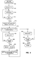
- Figure 3 is a flow chart of a method for producing a biphasic waveform having selected constant positive and negative tilts.
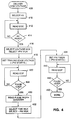
- Figure 4 is a flow chart of a method for producing a biphasic waveform with a selected constant tilt positive phase and a negative phase the duration of which is related to the duration of the measured positive phase duration.
- the invention is directed to programmable control circuitry for an implantable defibrillator output stage that generates biphasic defibrillation waveforms having selected constant tilt.
- the defibrillator has an on-board microprocessor and the control circuitry acts as a peripheral to the microprocessor.
- a control system which comprises functional modules and addresses that the microprocessor can read or write.
- Fig. 3 is a flow diagram that will be used in conjunction with the Fig. 2 block diagram to describe how a biphasic waveform having selected constant tilt positive and negative pulses can be generated.
- the microprocessor decides that a defibrillation output is necessary. This could be due to the automatic detection of fibrillation by the device, or due to an external command from the physician, or due to any other reason.
- a pulse Before a pulse can be delivered, energy must be stored on the defibrillation capacitor 200 (Fig. 2), which typically has a value of about 150 microfarads.
- the microprocessor addresses the high voltage converter 210 to command it to start charging the defibrillation capacitor 200 to a selected voltage (address "select HV ⁇ 212).
- the microprocessor starts a polling loop by reading "EOC” 214.
- "EOC” is the "end-of-convert” signal from the high voltage converter 210 and signifies that the converter has finished charging the capacitor 200 to the selected initial voltage.
- the microprocessor determines if the initial high voltage is ready at step 314.
- the microprocessor loops back to step 312. In some implementations it may be desirable for the microprocessor to attend to other tasks or to be disabled for periods to conserve current during polling loops. If, at step 314, the microprocessor finds that the defibrillator capacitor 200 is charged to the selected initial voltage, then the defibrillation system is prepared for delivery of a positive pulse.
- the pulse width of the positive pulse is determined by the length of time required for the defibrillator capacitor to decay to a selected decay voltage. If, in this illustrative example, the selected peak voltage is 500 volts, then 200 volts would be a reasonable decay voltage for the trailing edge voltage of the positive pulse to assure an effective negative phase (a trailing edge voltage of 100 volts for the negative phase will be used for this example).
- the microprocessor manipulates the controls of two multiplexers 212 and 214 to set the output stage to terminate the positive pulse when the selected trailing edge is detected on the defibrillation capacitor 200.
- Multiplexer 212 selects the signal flow to either generate a positive pulse or a negative pulse.
- the microprocessor addresses "+/-select" 213 to choose a positive pulse.
- Multiplexer 214 selects the signal flow to either produce a pulse with a selected time duration or a pulse which terminates when a selected decay voltage is detected on the defibrillator capacitor 200
- the microprocessor addresses "time/voltage select" 215 to choose a pulse which terminates when a selected decay voltage is detected.
- the positive pulse is started by the microprocessor at step 318 by addressing "Trailing voltage select” 222 and setting the selected trailing edge voltage to 200 volts. Since the voltage on the defibrillator capacitor 200 is at 500 volts, the output 221 of the trailing voltage detector 220 goes high. This signal 221 goes through multiplexer 214 to line 223, through multiplexer 212 to the positive pulse input 225 of the biphasic output stage 240 which generates a positive defibrillation output as long as positive pulse input 225 is asserted.
- Trailing voltage detector 220 maintains signal 221 high until the voltage on the defibrillator capacitor 200 has decayed to less than the trailing voltage selected by address 222. In this example, when the capacitor voltage decays to 200 volts, the trailing voltage detector 220 responds by forcing its output 221 low. This signal goes through multiplexer 214, line 223, and Trailing voltage detect 222 to the positive pulse input control 225 of the biphasic output stage 240, terminating the positive pulse.
- the microprocessor While the positive pulse is being generated, the microprocessor waits in a polling loop for the pulse to end.
- the microprocessor reads "EOP" at step 320.
- "EOP” is the "end-of-pulse” signal and is the same as line 223 discussed above. As long as the pulse is being generated, “EOP” is high; when the pulse is over, “EOP” goes low. Having read "EOP” at step 320, the microprocessor checks to see if the pulse is over at step 322. If the pulse is not over, the microprocessor loops back to step 320. When the positive pulse ends, the microprocessor sets up the defibrillator system to produce the negative pulse.
- the microprocessor addresses the "+/- select" 213 multiplexer 212 to select a negative pulse.
- the negative pulse is started by the microprocessor at step 326 by addressing "Trailing voltage select” 222 and setting the selected trailing edge voltage to 100 volts (in this example). Since the voltage on the defibrillator capacitor 200 is at 200 volts, the output 221 of the trailing voltage detector 220 goes high. This signal 221 goes through multiplexer 214 to line 223, through multiplexer 212 to the negative pulse input 226 of the biphasic output stage 240 which generates a negative defibrillation output as long as negative pulse input 226 is asserted.
- Trailing voltage detector 220 maintains signal 221 high until the voltage on the defibrillator capacitor 200 has decayed to less than the trailing voltage selected by address 222. In this example, when the capacitor voltage decays to 100 volts, the trailing voltage detector 220 responds by forcing its output 221 low. This signal goes through multiplexer 214 to line 223 and Trailing voltage select 222 to the negative pulse input control 226 of the biphasic output stage 240, terminating the negative pulse.
- the microprocessor While the negative pulse is being generated, the microprocessor waits in a polling loop for the pulse to end. The microprocessor reads "EOP" at step 330. As long as the pulse is being generated, “EOP" is high; when the pulse is over, “EOP” goes low. Having read "EOP” at step 330, the microprocessor checks to see if the pulse is over at 332. If the pulse is not over, then the microprocessor loops back to step 330. When the negative pulse ends, the microprocessor exits the program flow at step 390.
- Fig. 4 is a flow diagram that will be used in conjunction with the Fig. 2 block diagram to describe how a biphasic waveform having a positive pulse of selected constant tilt and a negative pulse duration related to the positive pulse duration can be generated. Generation of the positive pulse is accomplished in the same manner as described above in conjunction with Fig. 3, but is repeated here for completeness.
- the microprocessor decides that a defibrillation output is necessary. Before a pulse can be delivered, however, energy must be stored on the defibrillation capacitor 200, which typically has a value of about 150 microfarads.
- the microprocessor addresses the high voltage converter 210 to command it to start charging the defibrillation capacitor 200 to the selected initial voltage (address "select HV ⁇ 212).
- the microprocessor starts a polling loop by reading "EOC” 214.
- EOC is the end-of-convert signal from the high voltage converter 210 and signifies that the converter has finished charging the capacitor 200 to the selected voltage.
- the microprocessor determines if the high voltage is ready at 414.
- the microprocessor finds that the defibrillator capacitor 200 is charged to the selected initial voltage, then the defibrillator system is prepared for delivery of a positive pulse.
- the pulse width is determined by the length of time required for the defibrillator capacitor to decay to a selected decay voltage. If, in this illustrative example, the selected peak voltage is 500 volts, then 200 volts would be a reasonable target voltage for the trailing edge voltage of the positive pulse to assure an effective negative phase.
- the microprocessor manipulates the controls of two multiplexers to set the output stage to terminate the pulse when the selected trailing edge is detected on the defibrillation capacitor 200.
- Multiplexer 212 selects the signal flow to either generate a positive pulse or a negative pulse.
- the microprocessor addresses "+/select" 213 to choose a positive pulse.
- Multiplexer 214 selects the signal flow to either produce a pulse with a timed duration or a pulse which terminates when a selected decay voltage is detected on the defibrillator capacitor 200.
- the microprocessor addresses "time/voltage select" 215 to choose a pulse which terminates when a selected decay voltage is detected.
- the positive pulse is started by the microprocessor at step 418 by addressing "Trailing voltage select” 222 and setting the selected trailing edge voltage to 200 volts (in this example). Since the voltage on the defibrillator capacitor 200 is at 500 volts, the output 221 of the trailing voltage detector 220 goes high. This signal 221 goes through multiplexer 214 to line 223 and through multiplexer 212 to the positive pulse input 225 of the biphasic output stage 240 which generates a positive defibrillation output as long as positive pulse input 225 is asserted.
- Trailing voltage detector 220 maintains signal 221 high until the voltage on the defibrillator capacitor 200 has decayed to less than the trailing voltage selected by address 222. In this example, when the capacitor voltage decays to 200 volts, the trailing voltage detector 220 responds by forcing its output 221 low. This signal goes through 214, 223, and 222 to the positive pulse input control 225 of the biphasic output stage 240, terminating the positive pulse.
- the microprocessor While the positive pulse is being generated, the microprocessor waits in a polling loop for the pulse to end.
- the microprocessor reads "EOP" at step 420.
- "EOP" is the end-of-pulse signal and is the same as line 223 discussed above. As long as the pulse is being generated, “EOP” is high; when the-pulse is over “EOP” goes low. Having read "EOP” at step 420, the microprocessor checks to see if the pulse is over at step 422. If the pulse is not over, then the microprocessor loops back to step 420. When the positive pulse ends, the microprocessor sets up the hardware to produce the negative pulse which is to have a duration related to the positive pulse (in this example, the negative pulse will be set equal in duration to the positive pulse).
- the pulse duration is dependant upon the impedance of the patient's heart. For example, a comparatively low impedance of 25 ohms would result in a shorter pulse duration of about 3.4 milliseconds (for a 150 microfarad capacitor 200), while a 50 of patient impedance would result in a pulse duration of 6.8 milliseconds.
- the microprocessor addresses the pulse width counter 230 (address "pulse width read” 232) to determine the positive phase pulse duration.
- the pulse width counter 230 measures the duration of "EOP” 223.
- the address "pulse width read” 232 contains the duration of the positive pulse.
- the microprocessor stores the duration of the positive pulse width for future use.
- the microprocessor manipulates the controls of two multiplexers 212 and 214 to set the output stage to produce a negative pulse with a timed duration.
- Multiplexer 212 selects the signal flow to either generate a positive pulse or a negative pulse.
- the microprocessor addresses "+/select" 213 to choose a negative pulse.
- Multiplexer 214 selects the signal flow to either produce a pulse with a timed duration or a pulse which terminates when a selected decay voltage is detected on the defibrillator capacitor 200.
- the microprocessor addresses "time/voltage select" 215 to choose a pulse with a timed duration.
- the negative pulse is started by the microprocessor at step 434 by writing to the pulse width timer 250 address "pulse width select" 252)
- the pulse width timer produces a pulse of a duration which the microprocessor sets by writing a value to address "pulse width select" 252.
- the microprocessor makes the duration of the negative phase the same as the duration of the positive phase.
- the microprocessor writes into the pulse width timer 250 the value of the positive phase duration which it read from "pulse width read” 232 and stored. If the microprocessor was to make the negative phase twice the duration of the positive phase, then the microprocessor would multiply by two the positive phase duration (which it read from "pulse width read” 232 and stored) before writing it into the pulse width timer 250.
- the negative phase duration can be made related in any mathematical way to the positive phase duration by manipulating the data representation of the positive phase duration read from "pulse width read” 232.
- the microprocessor By writing to the pulse width timer 252, at step 434, the microprocessor starts the negative pulse.
- the pulse width timer 250 produces a pulse the duration of which is set by the data the microprocessor wrote to address "pulse width select" 252 (which is equal to the positive pulse duration read from address "pulse width read” 232 in this example).
- the pulse from the pulse width timer 250 passes through multiplexer 214 and multiplexer 212 to the negative pulse input 226 of the biphasic output stage 240.
- the biphasic output stage 240 applies the negative phase output to the heart 290 for as long as its input 226 is asserted.
- the microprocessor While the negative pulse is being generated, the microprocessor waits in a polling loop for the pulse to end. The microprocessor reads "EOP" at step 440. As long as the pulse is being generated, "EOP" is high; when the pulse is over, “EOP” goes low. Having read "EOP” at step 440, the microprocessor checks to see if the pulse is over at step 442. If the pulse is not over, then the microprocessor loops back to step 440. When the negative pulse ends, the microprocessor exits the program flow at step 490.
Abstract
Description
- The present invention relates to implantable medical devices and, in particular, to a programmable defibrillator capable of delivering a configurable biphasic waveform.
- Implantable defibrillators use truncated exponential waveforms to defibrillate the heart. The earliest devices used monophasic waveforms. More recent clinical investigations have evaluated the increased effectiveness of biphasic waveforms. See Troup, Implantable Cardioverters and Defibrillators, Current Problems in Cardiology, Volume XIV, Number 12, December 1989, pages 729-744. Some investigators have even recommended the use of triphasic waveforms as the most effective waveform for defibrillating a heart. See U.S. Patent 4,637,397 issued to Jones and Jones on January 20, 1987.
- As described by Troup, monophasic waveforms are typically produced using silicon controlled rectifier (SCR) technology that truncates the pulse by "dumping" the energy on the defibrillator capacitor. This leaves no energy available on the capacitor for producing multiphasic waveforms.
- As further described by Troup, there have been two methods available for truncation of a monophasic defibrillation waveform. According to one method, pulse truncation is accomplished by comparing the capacitor voltage to a reference voltage which is usually chosen as a function of the waveform leading edge voltage. The result is a defibrillation pulse with a constant ratio of trailing edge to leading edge voltage, or a "constant tilt" pulse.
- Defibrillation pulse "tilt", described as percent tilt, is defined as follows:

- According to the second method, the defibrillation pulse is truncated by a timing circuit so that the pulse duration is constant.
- Biphasic waveform generators have used MOS switches to produce the defibrillator output. The MOS switch technique is better suited to multiphasic waveforms since the defibrillator capacitor does not need to be "dumped" to truncate the pulse.
- Prior art biphasic waveforms have been programmable in terms of pulse duration. The disadvantage of programming biphasic waveforms in terms of duration can be seen in Fig. 1.
Panel 1 of Fig. 1 shows a conventional biphasic waveform with a 50 ohm load.Panel 2 shows a conventional biphasic waveform with the same duration of phases with a 25 ohm load. With a 50 ohm load, there is adequate residual voltage to produce an effective negative phase of the biphasic waveform. However, at the same pulse durations, with a 25 ohm load, the voltage during the positive phase has decayed to the point where very little is left for the negative phase. - While it is possible to select optimal pulse durations for a given patient impedance, the patient impedance may change. In particular, for higher defibrillation voltages, the patient impedance is lower. In addition, over time, the lead impedance may increase due to the build-up of scar tissue.
- Due to their small size and battery operation, implantable defibrillators have limited output energy capability. It is not unusual for an implantable defibrillator to have only slightly more output capability than is required to defibrillate a patient. This lack of safety margin makes it all the more important that the output energy that is available is used in the most effective manner. While biphasic waveforms are a step in the right direction, the optimal settings for the positive and negative phase durations have not been addressed in the prior art.
- U.S. Patent No. 4,850,357 issued to Stanley M. Bach, Jr. on July 25, 1989, discloses a circuit for generating a biphasic defibrillation waveform wherein both the positive and negative phases have constant tilt. However, the Bach, Jr. defibrillator generates a biphasic waveform having fixed characteristics. That is, only a single type of waveform can be delivered that has a first positive pulse having a specified constant tilt and a second negative pulse also having a specified constant tilt. Thus, the Back defibrillator circuit provides none of the therapeutic flexibility that is desirable in restoring rhythm to a fibrillating heart.
- The present invention provides a microprocessor controlled output stage that allows for greater flexibility than has been available in defining a biphasic defibrillation waveform. In accordance with the invention, the biphasic waveform generator may be programmed to provide either positive and negative phases having selected constant tilt or a positive phase having a selected constant tilt and a negative phase having a duration that is related to the duration of the positive phase. The disclosed apparatus can also produce conventional multiphasic waveforms, if desired.
- A better understanding of the features and advantages of the present invention will be obtained by reference to the following detailed description and accompanying drawings which set forth an illustrative embodiment in which the principles of the invention are utilized.
- Figure 1 provides a comparison between prior art biphasic waveforms and configurable biphasic waveforms generated in accordance with the present invention.
- Figure 2 is a block diagram illustrating an embodiment of an apparatus for generating a configurable, biphasic waveform in accordance with the present invention.
- Figure 3 is a flow chart of a method for producing a biphasic waveform having selected constant positive and negative tilts.
- Figure 4 is a flow chart of a method for producing a biphasic waveform with a selected constant tilt positive phase and a negative phase the duration of which is related to the duration of the measured positive phase duration.
- The invention is directed to programmable control circuitry for an implantable defibrillator output stage that generates biphasic defibrillation waveforms having selected constant tilt. In the disclosed embodiment, the defibrillator has an on-board microprocessor and the control circuitry acts as a peripheral to the microprocessor.
- With a biphasic waveform, where both phases have constant tilt, sufficient voltage for the negative phase is assured, as shown in
panels Panel 3 shows a constant tilt biphasic waveform with a 50 ohm load.Panel 4 shows a biphasic waveform with the same constant tilt with a 25 ohm load. The initial voltage on the biphasic waveform generated by the apparatus of the invention is the same in both cases. With the inventive apparatus, the amount of tilt in each phase is independently programmable. Since J = 0.5 * C (Vi² -Vf²); constant tilt can also be expressed as constant energy where the energy is independent, to some extent, from the initial voltage. - With a multiphase constant tilt defibrillation waveform, the duration of each phase of the waveform is dependant upon the patient impedance. Some studies (Tang, et al, Ventricular Defibrillation Using Biphasic Waveforms: The Importance of Phasic Duration, JACC Vol. 13, No. 1, January 1989) support the idea that the relative durations of the phases of a biphasic waveform are important in determining its efficacy. Therefore, it is desirable to be able to measure the duration of the first, constant tilt phase of a biphasic waveform and then set the negative phase duration to some percentage of the measured positive phase duration. This is a further capability of the disclosed apparatus, thus providing the ability to optimize multiphasic waveform durations.
- Referring to Fig. 2, in the illustrated embodiment of the invention, a control system is used which comprises functional modules and addresses that the microprocessor can read or write.
- Fig. 3 is a flow diagram that will be used in conjunction with the Fig. 2 block diagram to describe how a biphasic waveform having selected constant tilt positive and negative pulses can be generated.
- Referring to Figs. 2 and 3 at
step 300 of the Fig. 3 flowchart, the microprocessor decides that a defibrillation output is necessary. This could be due to the automatic detection of fibrillation by the device, or due to an external command from the physician, or due to any other reason. - Before a pulse can be delivered, energy must be stored on the defibrillation capacitor 200 (Fig. 2), which typically has a value of about 150 microfarads.
- At
step 310, the microprocessor addresses thehigh voltage converter 210 to command it to start charging thedefibrillation capacitor 200 to a selected voltage (address "select HV˝ 212). - At
step 312, the microprocessor starts a polling loop by reading "EOC" 214. "EOC" is the "end-of-convert" signal from thehigh voltage converter 210 and signifies that the converter has finished charging thecapacitor 200 to the selected initial voltage. After reading "EOC" atstep 312, the microprocessor determines if the initial high voltage is ready atstep 314. - If the initial high voltage is not ready, then the microprocessor loops back to
step 312. In some implementations it may be desirable for the microprocessor to attend to other tasks or to be disabled for periods to conserve current during polling loops. If, atstep 314, the microprocessor finds that thedefibrillator capacitor 200 is charged to the selected initial voltage, then the defibrillation system is prepared for delivery of a positive pulse. - The pulse width of the positive pulse is determined by the length of time required for the defibrillator capacitor to decay to a selected decay voltage. If, in this illustrative example, the selected peak voltage is 500 volts, then 200 volts would be a reasonable decay voltage for the trailing edge voltage of the positive pulse to assure an effective negative phase (a trailing edge voltage of 100 volts for the negative phase will be used for this example).
- At
step 316, the microprocessor manipulates the controls of twomultiplexers defibrillation capacitor 200.Multiplexer 212 selects the signal flow to either generate a positive pulse or a negative pulse. - At
step 316, the microprocessor addresses "+/-select" 213 to choose a positive pulse.Multiplexer 214 selects the signal flow to either produce a pulse with a selected time duration or a pulse which terminates when a selected decay voltage is detected on thedefibrillator capacitor 200 Atstep 316, the microprocessor addresses "time/voltage select" 215 to choose a pulse which terminates when a selected decay voltage is detected. - The positive pulse is started by the microprocessor at
step 318 by addressing "Trailing voltage select" 222 and setting the selected trailing edge voltage to 200 volts. Since the voltage on thedefibrillator capacitor 200 is at 500 volts, the output 221 of the trailingvoltage detector 220 goes high. This signal 221 goes throughmultiplexer 214 toline 223, throughmultiplexer 212 to thepositive pulse input 225 of thebiphasic output stage 240 which generates a positive defibrillation output as long aspositive pulse input 225 is asserted. - Once the positive pulse is started, the voltage on the defibrillator capacitor starts to decline as current flows into the patient's heart 290. Trailing
voltage detector 220 maintains signal 221 high until the voltage on thedefibrillator capacitor 200 has decayed to less than the trailing voltage selected byaddress 222. In this example, when the capacitor voltage decays to 200 volts, the trailingvoltage detector 220 responds by forcing its output 221 low. This signal goes throughmultiplexer 214,line 223, and Trailing voltage detect 222 to the positivepulse input control 225 of thebiphasic output stage 240, terminating the positive pulse. - While the positive pulse is being generated, the microprocessor waits in a polling loop for the pulse to end. The microprocessor reads "EOP" at
step 320. "EOP" is the "end-of-pulse" signal and is the same asline 223 discussed above. As long as the pulse is being generated, "EOP" is high; when the pulse is over, "EOP" goes low. Having read "EOP" atstep 320, the microprocessor checks to see if the pulse is over atstep 322. If the pulse is not over, the microprocessor loops back tostep 320. When the positive pulse ends, the microprocessor sets up the defibrillator system to produce the negative pulse. - At
step 324, the microprocessor addresses the "+/- select" 213multiplexer 212 to select a negative pulse. The negative pulse is started by the microprocessor atstep 326 by addressing "Trailing voltage select" 222 and setting the selected trailing edge voltage to 100 volts (in this example). Since the voltage on thedefibrillator capacitor 200 is at 200 volts, the output 221 of the trailingvoltage detector 220 goes high. This signal 221 goes throughmultiplexer 214 toline 223, throughmultiplexer 212 to thenegative pulse input 226 of thebiphasic output stage 240 which generates a negative defibrillation output as long asnegative pulse input 226 is asserted. - Once the negative pulse is started, the voltage on the
defibrillator capacitor 200 starts to decay again as current flows into the patient's heart 290. Trailingvoltage detector 220 maintains signal 221 high until the voltage on thedefibrillator capacitor 200 has decayed to less than the trailing voltage selected byaddress 222. In this example, when the capacitor voltage decays to 100 volts, the trailingvoltage detector 220 responds by forcing its output 221 low. This signal goes throughmultiplexer 214 toline 223 and Trailing voltage select 222 to the negativepulse input control 226 of thebiphasic output stage 240, terminating the negative pulse. - While the negative pulse is being generated, the microprocessor waits in a polling loop for the pulse to end. The microprocessor reads "EOP" at
step 330. As long as the pulse is being generated, "EOP" is high; when the pulse is over, "EOP" goes low. Having read "EOP" atstep 330, the microprocessor checks to see if the pulse is over at 332. If the pulse is not over, then the microprocessor loops back tostep 330. When the negative pulse ends, the microprocessor exits the program flow atstep 390. - Fig. 4 is a flow diagram that will be used in conjunction with the Fig. 2 block diagram to describe how a biphasic waveform having a positive pulse of selected constant tilt and a negative pulse duration related to the positive pulse duration can be generated. Generation of the positive pulse is accomplished in the same manner as described above in conjunction with Fig. 3, but is repeated here for completeness.
- At
step 400, the microprocessor decides that a defibrillation output is necessary. Before a pulse can be delivered, however, energy must be stored on thedefibrillation capacitor 200, which typically has a value of about 150 microfarads. Atstep 410, the microprocessor addresses thehigh voltage converter 210 to command it to start charging thedefibrillation capacitor 200 to the selected initial voltage (address "select HV˝ 212). - At
step 412, the microprocessor starts a polling loop by reading "EOC" 214. "EOC" is the end-of-convert signal from thehigh voltage converter 210 and signifies that the converter has finished charging thecapacitor 200 to the selected voltage. After reading "EOC" atstep 412, the microprocessor determines if the high voltage is ready at 414. - If the high voltage is not ready, then the microprocessor loops back to
step 412. In some implementations, it may be desirable for the microprocessor to attend to other tasks or to be disabled for periods to conserve current during polling loops. If, atstep 414, the microprocessor finds that thedefibrillator capacitor 200 is charged to the selected initial voltage, then the defibrillator system is prepared for delivery of a positive pulse. The pulse width is determined by the length of time required for the defibrillator capacitor to decay to a selected decay voltage. If, in this illustrative example, the selected peak voltage is 500 volts, then 200 volts would be a reasonable target voltage for the trailing edge voltage of the positive pulse to assure an effective negative phase. - At
step 416, the microprocessor manipulates the controls of two multiplexers to set the output stage to terminate the pulse when the selected trailing edge is detected on thedefibrillation capacitor 200. -
Multiplexer 212 selects the signal flow to either generate a positive pulse or a negative pulse. Atstep 416, the microprocessor addresses "+/select" 213 to choose a positive pulse.Multiplexer 214 selects the signal flow to either produce a pulse with a timed duration or a pulse which terminates when a selected decay voltage is detected on thedefibrillator capacitor 200. Atstep 416, the microprocessor addresses "time/voltage select" 215 to choose a pulse which terminates when a selected decay voltage is detected. - The positive pulse is started by the microprocessor at
step 418 by addressing "Trailing voltage select" 222 and setting the selected trailing edge voltage to 200 volts (in this example). Since the voltage on thedefibrillator capacitor 200 is at 500 volts, the output 221 of the trailingvoltage detector 220 goes high. This signal 221 goes throughmultiplexer 214 toline 223 and throughmultiplexer 212 to thepositive pulse input 225 of thebiphasic output stage 240 which generates a positive defibrillation output as long aspositive pulse input 225 is asserted. - Once the positive pulse is started, the voltage on the defibrillator capacitor starts to decline as current flows into the patient's heart 290. Trailing
voltage detector 220 maintains signal 221 high until the voltage on thedefibrillator capacitor 200 has decayed to less than the trailing voltage selected byaddress 222. In this example, when the capacitor voltage decays to 200 volts, the trailingvoltage detector 220 responds by forcing its output 221 low. This signal goes through 214, 223, and 222 to the positivepulse input control 225 of thebiphasic output stage 240, terminating the positive pulse. - While the positive pulse is being generated, the microprocessor waits in a polling loop for the pulse to end. The microprocessor reads "EOP" at
step 420. "EOP" is the end-of-pulse signal and is the same asline 223 discussed above. As long as the pulse is being generated, "EOP" is high; when the-pulse is over "EOP" goes low. Having read "EOP" atstep 420, the microprocessor checks to see if the pulse is over atstep 422. If the pulse is not over, then the microprocessor loops back tostep 420. When the positive pulse ends, the microprocessor sets up the hardware to produce the negative pulse which is to have a duration related to the positive pulse (in this example, the negative pulse will be set equal in duration to the positive pulse). - Since the positive phase pulse was terminated by the
capacitor 200 reaching a selected decay voltage (200 volts in this example), the pulse duration is dependant upon the impedance of the patient's heart. For example, a comparatively low impedance of 25 ohms would result in a shorter pulse duration of about 3.4 milliseconds (for a 150 microfarad capacitor 200), while a 50 of patient impedance would result in a pulse duration of 6.8 milliseconds. - Once the positive pulse is over, at
step 430 the microprocessor addresses the pulse width counter 230 (address "pulse width read" 232) to determine the positive phase pulse duration. The pulse width counter 230 measures the duration of "EOP" 223. Thus, the address "pulse width read" 232 contains the duration of the positive pulse. The microprocessor stores the duration of the positive pulse width for future use. - At
step 432, the microprocessor manipulates the controls of twomultiplexers Multiplexer 212 selects the signal flow to either generate a positive pulse or a negative pulse. Atstep 432, the microprocessor addresses "+/select" 213 to choose a negative pulse.Multiplexer 214 selects the signal flow to either produce a pulse with a timed duration or a pulse which terminates when a selected decay voltage is detected on thedefibrillator capacitor 200. Atstep 432 the microprocessor addresses "time/voltage select" 215 to choose a pulse with a timed duration. - The negative pulse is started by the microprocessor at
step 434 by writing to thepulse width timer 250 address "pulse width select" 252) The pulse width timer produces a pulse of a duration which the microprocessor sets by writing a value to address "pulse width select" 252. In this example, the microprocessor makes the duration of the negative phase the same as the duration of the positive phase. To do this, the microprocessor writes into thepulse width timer 250 the value of the positive phase duration which it read from "pulse width read" 232 and stored. If the microprocessor was to make the negative phase twice the duration of the positive phase, then the microprocessor would multiply by two the positive phase duration (which it read from "pulse width read" 232 and stored) before writing it into thepulse width timer 250. As should be clear, the negative phase duration can be made related in any mathematical way to the positive phase duration by manipulating the data representation of the positive phase duration read from "pulse width read" 232. - By writing to the
pulse width timer 252, atstep 434, the microprocessor starts the negative pulse. Thepulse width timer 250 produces a pulse the duration of which is set by the data the microprocessor wrote to address "pulse width select" 252 (which is equal to the positive pulse duration read from address "pulse width read" 232 in this example). The pulse from thepulse width timer 250 passes throughmultiplexer 214 andmultiplexer 212 to thenegative pulse input 226 of thebiphasic output stage 240. Thebiphasic output stage 240 applies the negative phase output to the heart 290 for as long as itsinput 226 is asserted. - While the negative pulse is being generated, the microprocessor waits in a polling loop for the pulse to end. The microprocessor reads "EOP" at
step 440. As long as the pulse is being generated, "EOP" is high; when the pulse is over, "EOP" goes low. Having read "EOP" atstep 440, the microprocessor checks to see if the pulse is over atstep 442. If the pulse is not over, then the microprocessor loops back tostep 440. When the negative pulse ends, the microprocessor exits the program flow atstep 490. - As should be apparent, many combinations of selected constant tilt and selected constant duration (or related duration) multiphasic waveforms can be produced under microprocessor control using the apparatus disclosed above.
- Thus, it should be understood that various alternatives to the embodiments of the invention described herein may be employed in practicing the invention. It is intended that the following claims define the scope of the invention and that methods and apparatus within the scope of these claims and their equivalents to covered thereby.
Claims (6)
- A programmable implantable medical device utilizable for delivering a defibrillation waveform to a heart, the implantable medical device comprising:(a) defibrillation electrode means adapted to be connected to the heart;(b) waveform generator means connected to the defibrillation electrode means for generating the defibrillation waveform, the defibrillation waveform including at least one constant tilt pulse; and(c) programmable means connected to the waveform generator means for determining the constant tilt of the at least one pulse.
- An implantable medical device utilizable for delivering a configurable biphasic defibrillation waveform to a heart, the medical device comprising:(a) charge storage means;(b) charging means for charging the storage means to an initial selected voltage;(c) control means for initiating delivery of a first defibrillation pulse of a first polarity to the heart when the storage means stores the initial selected voltage;(d) trailing voltage detector means for monitoring the decay of the voltage of the charge storage means during delivery of the first defibrillation pulse; and(e) programmable disable means for terminating the first defibrillation pulse when the voltage of the charge storage means decays to a programmed decay voltage.
- An implantable medical device as in claim 2 wherein the control means includes means for initiating delivery of a second defibrillation pulse of a second polarity to the heart when the voltage of the charge storage means decays to the programmed decay voltage and the trailing voltage detector means includes means for monitoring the decay of the voltage of the charge storage means from the programmed decay voltage to a final decay voltage during delivery of the second defibrillation pulse, and the disable means includes means for terminating the second defibrillation pulse when the voltage of the charged storage means decays to the final decay voltage.
- An implantable medical device as in claim 3 wherein the final decay voltage is programmable.
- An implantable medical device as in claim 2 wherein the control means includes means for initiating delivery of a second defibrillation pulse of a second polarity to the heart when the voltage of the charge storage means decays to the programmed decay voltage and further comprising:(a) timer means for measuring the duration of the first defibrillation pulse; and(b) means for delivering a second defibrillation pulse of a second polarity to the heart, the second defibrillation pulse having a duration corresponding to the duration of the first defibrillation pulse.
- An implantable medical device as in claim 5 wherein the duration of the second defibrillation pulse is programmable.
Applications Claiming Priority (2)
| Application Number | Priority Date | Filing Date | Title |
|---|---|---|---|
| US62925290A | 1990-12-18 | 1990-12-18 | |
| US629252 | 1990-12-18 |
Publications (3)
| Publication Number | Publication Date |
|---|---|
| EP0491649A2 true EP0491649A2 (en) | 1992-06-24 |
| EP0491649A3 EP0491649A3 (en) | 1992-12-16 |
| EP0491649B1 EP0491649B1 (en) | 1996-09-25 |
Family
ID=24522212
Family Applications (1)
| Application Number | Title | Priority Date | Filing Date |
|---|---|---|---|
| EP91630111A Revoked EP0491649B1 (en) | 1990-12-18 | 1991-12-12 | Apparatus for producing configurable biphasic defibrillation waveforms |
Country Status (7)
| Country | Link |
|---|---|
| US (1) | US5352239A (en) |
| EP (1) | EP0491649B1 (en) |
| AT (1) | ATE143280T1 (en) |
| CA (1) | CA2057820C (en) |
| DE (1) | DE69122365T2 (en) |
| DK (1) | DK0491649T3 (en) |
| ES (1) | ES2092554T3 (en) |
Cited By (21)
| Publication number | Priority date | Publication date | Assignee | Title |
|---|---|---|---|---|
| EP0576109A2 (en) * | 1992-06-22 | 1993-12-29 | Incontrol, Inc. | Pulse generator for use in an implantable atrial defibrillator |
| EP0589252A2 (en) * | 1992-09-25 | 1994-03-30 | Cardiac Pacemakers, Inc. | Fibrillation induction method for implantable devices |
| EP0589251A2 (en) * | 1992-09-25 | 1994-03-30 | Cardiac Pacemakers, Inc. | Method and apparatus for generating multiphasic defibrillation waveforms based on pulse width ratios |
| WO1995009672A1 (en) * | 1993-10-07 | 1995-04-13 | Cardiac Pacemakers, Inc. | Method and apparatus for generating adaptive n-phasic defibrillation waveforms |
| EP0712321A1 (en) * | 1993-08-06 | 1996-05-22 | Heartstream, Inc. | Electrotherapy method and apparatus |
| US5735879A (en) * | 1993-08-06 | 1998-04-07 | Heartstream, Inc. | Electrotherapy method for external defibrillators |
| WO2000001443A1 (en) * | 1998-07-02 | 2000-01-13 | Mower Morton M | Augmentation of electrical conduction and contractility by biphasic cardiac pacing |
| US6016442A (en) * | 1998-03-25 | 2000-01-18 | Cardiac Pacemakers, Inc. | System for displaying cardiac arrhythmia data |
| US6067470A (en) * | 1998-03-05 | 2000-05-23 | Mower Family Chf Treatment Irrevocable Trust | System and method for multiple site biphasic stimulation to revert ventricular arrhythmias |
| US6136019A (en) * | 1996-08-19 | 2000-10-24 | Mower Family Chf Treatment Irrevocable Trust | Augmentation of electrical conduction and contractility by biphasic cardiac pacing administered via the cardiac blood pool |
| US6141586A (en) * | 1996-08-19 | 2000-10-31 | Mower Family Chf Treatment Irrevocable Trust | Method and apparatus to allow cyclic pacing at an average rate just above the intrinsic heart rate so as to maximize inotropic pacing effects at minimal heart rates |
| US6141587A (en) * | 1996-08-19 | 2000-10-31 | Mower Family Chf Treatment Irrevocable Trust | Augmentation of muscle contractility by biphasic stimulation |
| US6178351B1 (en) | 1996-08-19 | 2001-01-23 | The Mower Family Chf Treatment Irrevocable Trust | Atrial sensing and multiple site stimulation as intervention means for atrial fibrillation |
| US6295470B1 (en) | 1996-08-19 | 2001-09-25 | The Mower Family Chf Treatment Irrevocable Trust | Antitachycardial pacing |
| US6405081B1 (en) | 1999-04-22 | 2002-06-11 | Koninklijke Philips Electronics N.V. | Damped biphasic energy delivery circuit for a defibrillator |
| US6453201B1 (en) | 1999-10-20 | 2002-09-17 | Cardiac Pacemakers, Inc. | Implantable medical device with voice responding and recording capacity |
| US6987998B2 (en) | 2001-02-28 | 2006-01-17 | Cardiac Pacemakers, Inc. | Cardiac rhythm management patient report |
| US7751892B2 (en) | 2003-05-07 | 2010-07-06 | Cardiac Pacemakers, Inc. | Implantable medical device programming apparatus having a graphical user interface |
| US8290585B2 (en) | 1996-08-19 | 2012-10-16 | Mr3 Medical, Llc | Augmentation of electrical conduction and contractility by biphasic cardiac pacing administered via the cardiac blood pool |
| US9399315B2 (en) | 2010-04-20 | 2016-07-26 | Snecma | Device for manufacturing a casing made of a composite material and manufacturing method using such a device |
| US9949687B2 (en) | 2000-12-15 | 2018-04-24 | Cardiac Pacemakers, Inc. | System and method for correlation of patient health information and device data |
Families Citing this family (31)
| Publication number | Priority date | Publication date | Assignee | Title |
|---|---|---|---|---|
| US6343232B1 (en) | 1966-08-19 | 2002-01-29 | Mower Chf Treatment Irrevocable Trust | Augmentation of muscle contractility by biphasic stimulation |
| US5534015A (en) * | 1992-02-18 | 1996-07-09 | Angeion Corporation | Method and apparatus for generating biphasic waveforms in an implantable defibrillator |
| US5468254A (en) * | 1993-07-26 | 1995-11-21 | Cardiac Pacemakers, Inc. | Method and apparatus for defibrillation using a multiphasic truncated exponential waveform |
| US5620465A (en) * | 1995-06-08 | 1997-04-15 | Survivalink Corporation | External defibrillator for producing and testing biphasic waveforms |
| WO1997038754A1 (en) * | 1996-04-12 | 1997-10-23 | Survivalink Corporation | External defibrillator having low capacitance and small time constant |
| US6411846B1 (en) | 1999-08-26 | 2002-06-25 | Survivalink Corporation | Method and apparatus for delivering a biphasic defibrillation pulse with variable energy |
| US5968080A (en) * | 1996-07-01 | 1999-10-19 | Survivalink Corporation | Method for determining the second phase of external defibrillator devices |
| US6263239B1 (en) | 1996-07-01 | 2001-07-17 | Survivalink Corporation | Method and apparatus for determining the second phase of defibrillator devices |
| US7908003B1 (en) | 1996-08-19 | 2011-03-15 | Mr3 Medical Llc | System and method for treating ischemia by improving cardiac efficiency |
| US7840264B1 (en) | 1996-08-19 | 2010-11-23 | Mr3 Medical, Llc | System and method for breaking reentry circuits by cooling cardiac tissue |
| US6411847B1 (en) | 1996-08-19 | 2002-06-25 | Morton M. Mower | Apparatus for applying cyclic pacing at an average rate just above the intrinsic heart rate |
| US8447399B2 (en) | 1996-08-19 | 2013-05-21 | Mr3 Medical, Llc | System and method for managing detrimental cardiac remodeling |
| US6337995B1 (en) | 1996-08-19 | 2002-01-08 | Mower Chf Treatment Irrevocable Trust | Atrial sensing and multiple site stimulation as intervention for atrial fibrillation |
| US5728139A (en) * | 1996-10-31 | 1998-03-17 | Hewlett-Packard Company | Automatic waveform selection for defibrillation |
| US5792189A (en) * | 1997-04-04 | 1998-08-11 | The Research Foundation Of State University Of New York | Defibrillation utilizing the dominant frequency of fibrillation |
| US6539255B1 (en) | 1998-07-16 | 2003-03-25 | Cardiac Science, Inc. | Full-tilt exponential defibrillation waveform |
| US6212429B1 (en) | 1998-10-13 | 2001-04-03 | Physio-Control Manufacturing Corporation | Method and apparatus for converting a monophasic defibrillator to a biphasic defibrillator |
| US6208896B1 (en) | 1998-11-13 | 2001-03-27 | Agilent Technologies, Inc. | Method and apparatus for providing variable defibrillation waveforms using switch-mode amplification |
| US6411845B1 (en) | 1999-03-04 | 2002-06-25 | Mower Chf Treatment Irrevocable Trust | System for multiple site biphasic stimulation to revert ventricular arrhythmias |
| US6718198B2 (en) | 1999-08-24 | 2004-04-06 | Cardiac Pacemakers, Inc. | Arrhythmia display |
| US6418340B1 (en) | 1999-08-20 | 2002-07-09 | Cardiac Pacemakers, Inc. | Method and system for identifying and displaying groups of cardiac arrhythmic episodes |
| US6665558B2 (en) | 2000-12-15 | 2003-12-16 | Cardiac Pacemakers, Inc. | System and method for correlation of patient health information and implant device data |
| US20030125771A1 (en) * | 2001-08-01 | 2003-07-03 | Medical Research Laboratories, Inc. | Multiphasic defibrillator utilizing controlled energy pulses |
| US8046060B2 (en) | 2005-11-14 | 2011-10-25 | Cardiac Pacemakers, Inc. | Differentiating arrhythmic events having different origins |
| CN102458573B (en) * | 2009-06-19 | 2015-02-25 | 皇家飞利浦电子股份有限公司 | Biphasic defibrillator waveform with adjustable second phase tilt |
| US9126055B2 (en) | 2012-04-20 | 2015-09-08 | Cardiac Science Corporation | AED faster time to shock method and device |
| AU2015218603B2 (en) | 2014-02-24 | 2019-12-05 | Element Science, Inc | External defibrillator |
| JP6981966B2 (en) | 2015-08-26 | 2021-12-17 | エレメント サイエンス, インクElement Science, Inc | Wearable device |
| US11524169B2 (en) | 2017-02-06 | 2022-12-13 | Medtronic, Inc. | Charge balanced cardiac pacing from high voltage circuitry of an extra-cardiovascular implantable cardioverter defibrillator system |
| US10946207B2 (en) | 2017-05-27 | 2021-03-16 | West Affum Holdings Corp. | Defibrillation waveforms for a wearable cardiac defibrillator |
| AU2019357613B2 (en) | 2018-10-10 | 2021-12-09 | Element Science, Inc. | Wearable medical device with disposable and reusable components |
Citations (3)
| Publication number | Priority date | Publication date | Assignee | Title |
|---|---|---|---|---|
| EP0280526A2 (en) * | 1987-02-27 | 1988-08-31 | Intermedics, Inc. | Biphasic waveforms for defibrillation |
| US4800883A (en) * | 1986-04-02 | 1989-01-31 | Intermedics, Inc. | Apparatus for generating multiphasic defibrillation pulse waveform |
| EP0326290A1 (en) * | 1988-01-19 | 1989-08-02 | Telectronics N.V. | Method and apparatus for applying asymmetric biphasic truncated exponential countershocks |
Family Cites Families (2)
| Publication number | Priority date | Publication date | Assignee | Title |
|---|---|---|---|---|
| US4708145A (en) * | 1982-06-01 | 1987-11-24 | Medtronic, Inc. | Sequential-pulse, multiple pathway defibrillation method |
| US4996984A (en) * | 1989-09-26 | 1991-03-05 | Eli Lilly And Company | Defibrillation method |
-
1991
- 1991-12-12 AT AT91630111T patent/ATE143280T1/en active
- 1991-12-12 EP EP91630111A patent/EP0491649B1/en not_active Revoked
- 1991-12-12 ES ES91630111T patent/ES2092554T3/en not_active Expired - Lifetime
- 1991-12-12 DK DK91630111.2T patent/DK0491649T3/en active
- 1991-12-12 DE DE69122365T patent/DE69122365T2/en not_active Revoked
- 1991-12-17 CA CA002057820A patent/CA2057820C/en not_active Expired - Fee Related
-
1993
- 1993-03-24 US US08/037,482 patent/US5352239A/en not_active Expired - Lifetime
Patent Citations (3)
| Publication number | Priority date | Publication date | Assignee | Title |
|---|---|---|---|---|
| US4800883A (en) * | 1986-04-02 | 1989-01-31 | Intermedics, Inc. | Apparatus for generating multiphasic defibrillation pulse waveform |
| EP0280526A2 (en) * | 1987-02-27 | 1988-08-31 | Intermedics, Inc. | Biphasic waveforms for defibrillation |
| EP0326290A1 (en) * | 1988-01-19 | 1989-08-02 | Telectronics N.V. | Method and apparatus for applying asymmetric biphasic truncated exponential countershocks |
Cited By (37)
| Publication number | Priority date | Publication date | Assignee | Title |
|---|---|---|---|---|
| EP0576109A3 (en) * | 1992-06-22 | 1994-12-21 | Incontrol Inc | Pulse generator for use in an implantable atrial defibrillator. |
| EP0576109A2 (en) * | 1992-06-22 | 1993-12-29 | Incontrol, Inc. | Pulse generator for use in an implantable atrial defibrillator |
| US5824018A (en) * | 1992-09-25 | 1998-10-20 | Cardiac Pacemakers, Inc. | Fibrillation induction method and system for implantable devices |
| EP0589252A2 (en) * | 1992-09-25 | 1994-03-30 | Cardiac Pacemakers, Inc. | Fibrillation induction method for implantable devices |
| EP0589251A2 (en) * | 1992-09-25 | 1994-03-30 | Cardiac Pacemakers, Inc. | Method and apparatus for generating multiphasic defibrillation waveforms based on pulse width ratios |
| EP0589252A3 (en) * | 1992-09-25 | 1994-12-07 | Cardiac Pacemakers Inc | Fibrillation induction method for implantable devices. |
| EP0589251A3 (en) * | 1992-09-25 | 1994-12-14 | Cardiac Pacemakers Inc | Method and apparatus for generating multiphasic defibrillation waveforms based on pulse width ratios. |
| US6047212A (en) * | 1993-08-06 | 2000-04-04 | Heartstream, Inc. | External defibrillator capable of delivering patient impedance compensated biphasic waveforms |
| US5735879A (en) * | 1993-08-06 | 1998-04-07 | Heartstream, Inc. | Electrotherapy method for external defibrillators |
| US5749904A (en) * | 1993-08-06 | 1998-05-12 | Heartstream, Inc. | Electrotherapy method utilizing patient dependent electrical parameters |
| US5749905A (en) * | 1993-08-06 | 1998-05-12 | Heartstream, Inc. | Electrotherapy method utilizing patient dependent electrical parameters |
| US5776166A (en) * | 1993-08-06 | 1998-07-07 | Heartstream, Inc. | Method for applying a multiphasic waveform |
| US5803927A (en) * | 1993-08-06 | 1998-09-08 | Heartstream, Inc. | Electrotherapy method and apparatus for external defibrillation |
| EP0712321A1 (en) * | 1993-08-06 | 1996-05-22 | Heartstream, Inc. | Electrotherapy method and apparatus |
| US5836978A (en) * | 1993-08-06 | 1998-11-17 | Heartstream, Inc. | Electrotherapy method for producing a multiphasic discharge based upon a patient-dependent electrical parameter and time |
| EP0712321A4 (en) * | 1993-08-06 | 1997-12-17 | Heartstream Inc | Electrotherapy method and apparatus |
| EP0997162A1 (en) * | 1993-08-06 | 2000-05-03 | Heartstream, Inc. | Electrotherapy apparatus |
| WO1995009672A1 (en) * | 1993-10-07 | 1995-04-13 | Cardiac Pacemakers, Inc. | Method and apparatus for generating adaptive n-phasic defibrillation waveforms |
| US6136019A (en) * | 1996-08-19 | 2000-10-24 | Mower Family Chf Treatment Irrevocable Trust | Augmentation of electrical conduction and contractility by biphasic cardiac pacing administered via the cardiac blood pool |
| US6295470B1 (en) | 1996-08-19 | 2001-09-25 | The Mower Family Chf Treatment Irrevocable Trust | Antitachycardial pacing |
| US8290585B2 (en) | 1996-08-19 | 2012-10-16 | Mr3 Medical, Llc | Augmentation of electrical conduction and contractility by biphasic cardiac pacing administered via the cardiac blood pool |
| US6178351B1 (en) | 1996-08-19 | 2001-01-23 | The Mower Family Chf Treatment Irrevocable Trust | Atrial sensing and multiple site stimulation as intervention means for atrial fibrillation |
| US6141587A (en) * | 1996-08-19 | 2000-10-31 | Mower Family Chf Treatment Irrevocable Trust | Augmentation of muscle contractility by biphasic stimulation |
| US6141586A (en) * | 1996-08-19 | 2000-10-31 | Mower Family Chf Treatment Irrevocable Trust | Method and apparatus to allow cyclic pacing at an average rate just above the intrinsic heart rate so as to maximize inotropic pacing effects at minimal heart rates |
| US6067470A (en) * | 1998-03-05 | 2000-05-23 | Mower Family Chf Treatment Irrevocable Trust | System and method for multiple site biphasic stimulation to revert ventricular arrhythmias |
| US6091990A (en) * | 1998-03-25 | 2000-07-18 | Cardiac Pacemakers, Inc. | System for grouping and displaying cardiac arrhythmia data |
| US6253102B1 (en) | 1998-03-25 | 2001-06-26 | Cardiac Pacemakers, Inc. | System for displaying cardiac arrhythmia data |
| US6016442A (en) * | 1998-03-25 | 2000-01-18 | Cardiac Pacemakers, Inc. | System for displaying cardiac arrhythmia data |
| US6301503B1 (en) | 1998-03-25 | 2001-10-09 | Cardiac Pacemakers, Inc. | System for grouping and displaying cardiac arrhythmia data |
| WO2000001443A1 (en) * | 1998-07-02 | 2000-01-13 | Mower Morton M | Augmentation of electrical conduction and contractility by biphasic cardiac pacing |
| US6405081B1 (en) | 1999-04-22 | 2002-06-11 | Koninklijke Philips Electronics N.V. | Damped biphasic energy delivery circuit for a defibrillator |
| US6453201B1 (en) | 1999-10-20 | 2002-09-17 | Cardiac Pacemakers, Inc. | Implantable medical device with voice responding and recording capacity |
| US6865424B2 (en) | 1999-10-20 | 2005-03-08 | Cardiac Pacemakers, Inc. | Implantable medical device with voice responding and recording capacity |
| US9949687B2 (en) | 2000-12-15 | 2018-04-24 | Cardiac Pacemakers, Inc. | System and method for correlation of patient health information and device data |
| US6987998B2 (en) | 2001-02-28 | 2006-01-17 | Cardiac Pacemakers, Inc. | Cardiac rhythm management patient report |
| US7751892B2 (en) | 2003-05-07 | 2010-07-06 | Cardiac Pacemakers, Inc. | Implantable medical device programming apparatus having a graphical user interface |
| US9399315B2 (en) | 2010-04-20 | 2016-07-26 | Snecma | Device for manufacturing a casing made of a composite material and manufacturing method using such a device |
Also Published As
| Publication number | Publication date |
|---|---|
| CA2057820C (en) | 1998-02-10 |
| ATE143280T1 (en) | 1996-10-15 |
| US5352239A (en) | 1994-10-04 |
| DE69122365T2 (en) | 1997-02-06 |
| EP0491649B1 (en) | 1996-09-25 |
| DK0491649T3 (en) | 1996-12-30 |
| CA2057820A1 (en) | 1992-06-19 |
| ES2092554T3 (en) | 1996-12-01 |
| EP0491649A3 (en) | 1992-12-16 |
| DE69122365D1 (en) | 1996-10-31 |
Similar Documents
| Publication | Publication Date | Title |
|---|---|---|
| EP0491649B1 (en) | Apparatus for producing configurable biphasic defibrillation waveforms | |
| US5531765A (en) | Method and apparatus for producing configurable biphasic defibrillation waveforms | |
| EP0553863B1 (en) | Dual capacitor biphasic defibrillator waveform generator employing selective connection of capacitors for each phase | |
| US5824018A (en) | Fibrillation induction method and system for implantable devices | |
| CA2088384C (en) | Defibrillator waveform generator for generating waveform of long duration | |
| EP0588126B1 (en) | Implantable heart defibrillator | |
| US5372606A (en) | Method and apparatus for generating adaptive n-phasic defibrillation waveforms | |
| US4637397A (en) | Triphasic wave defibrillation | |
| US6484056B2 (en) | System and method of generating a high efficiency biphasic defibrillation waveform for use in an implantable cardioverter/defibrillator (ICD) | |
| US5324309A (en) | Overlapping pulse cardioversion or defibrillation | |
| US5871505A (en) | Apparatus for generating biphasic waveforms in an implantable defibrillator | |
| US5549643A (en) | Optimal pulse defibrillator | |
| US5391186A (en) | Method and apparatus for utilizing short tau capacitors in an implantable cardioverter defibrillator | |
| US6954669B1 (en) | System and method of generating an optimal three-step defibrillation waveform for use in an implantable cardioverter/defibrillator (ICD) | |
| US5360435A (en) | Multiple pulse cardioversion or defibrillation | |
| US5591209A (en) | Implantable defibrillator system for generating an active biphasic waveform | |
| US6104954A (en) | High frequency lead testing apparatus in an implantable defibrillator | |
| EP0636041B1 (en) | Short-pulse cardioversion | |
| US20030125771A1 (en) | Multiphasic defibrillator utilizing controlled energy pulses | |
| US5813999A (en) | Implantable atrial defibrillator providing reduced cardioversion discomfort | |
| US5653740A (en) | Method and apparatus for induction of fibrillation | |
| EP0547878B1 (en) | Defibrillation system with a small capacitor | |
| EP0589251B1 (en) | Apparatus for generating multiphasic defibrillation waveforms based on pulse width ratios | |
| US5645573A (en) | Optimal pulse defibrillator |
Legal Events
| Date | Code | Title | Description |
|---|---|---|---|
| PUAI | Public reference made under article 153(3) epc to a published international application that has entered the european phase |
Free format text: ORIGINAL CODE: 0009012 |
|
| AK | Designated contracting states |
Kind code of ref document: A2 Designated state(s): AT BE CH DE DK ES FR GB GR IT LI NL SE |
|
| PUAL | Search report despatched |
Free format text: ORIGINAL CODE: 0009013 |
|
| AK | Designated contracting states |
Kind code of ref document: A3 Designated state(s): AT BE CH DE DK ES FR GB GR IT LI NL SE |
|
| 17P | Request for examination filed |
Effective date: 19921207 |
|
| 17Q | First examination report despatched |
Effective date: 19940928 |
|
| GRAG | Despatch of communication of intention to grant |
Free format text: ORIGINAL CODE: EPIDOS AGRA |
|
| GRAH | Despatch of communication of intention to grant a patent |
Free format text: ORIGINAL CODE: EPIDOS IGRA |
|
| GRAH | Despatch of communication of intention to grant a patent |
Free format text: ORIGINAL CODE: EPIDOS IGRA |
|
| GRAA | (expected) grant |
Free format text: ORIGINAL CODE: 0009210 |
|
| AK | Designated contracting states |
Kind code of ref document: B1 Designated state(s): AT BE CH DE DK ES FR GB GR IT LI NL SE |
|
| PG25 | Lapsed in a contracting state [announced via postgrant information from national office to epo] |
Ref country code: GR Free format text: LAPSE BECAUSE OF FAILURE TO SUBMIT A TRANSLATION OF THE DESCRIPTION OR TO PAY THE FEE WITHIN THE PRESCRIBED TIME-LIMIT Effective date: 19960925 |
|
| REF | Corresponds to: |
Ref document number: 143280 Country of ref document: AT Date of ref document: 19961015 Kind code of ref document: T |
|
| ET | Fr: translation filed | ||
| REF | Corresponds to: |
Ref document number: 69122365 Country of ref document: DE Date of ref document: 19961031 |
|
| REG | Reference to a national code |
Ref country code: ES Ref legal event code: FG2A Ref document number: 2092554 Country of ref document: ES Kind code of ref document: T3 |
|
| PGFP | Annual fee paid to national office [announced via postgrant information from national office to epo] |
Ref country code: DK Payment date: 19961216 Year of fee payment: 6 |
|
| ITF | It: translation for a ep patent filed |
Owner name: UFFICIO BREVETTI RICCARDI & C. |
|
| REG | Reference to a national code |
Ref country code: DK Ref legal event code: T3 |
|
| PLBQ | Unpublished change to opponent data |
Free format text: ORIGINAL CODE: EPIDOS OPPO |
|
| PLBI | Opposition filed |
Free format text: ORIGINAL CODE: 0009260 |
|
| PLBF | Reply of patent proprietor to notice(s) of opposition |
Free format text: ORIGINAL CODE: EPIDOS OBSO |
|
| 26 | Opposition filed |
Opponent name: BIOTRONIK MESS- UND THERAPIEGERAETE GMBH & CO INGE Effective date: 19970625 |
|
| NLR1 | Nl: opposition has been filed with the epo |
Opponent name: BIOTRONIK MESS- UND THERAPIEGERAETE GMBH & CO INGE |
|
| PGFP | Annual fee paid to national office [announced via postgrant information from national office to epo] |
Ref country code: GB Payment date: 19971203 Year of fee payment: 7 |
|
| PLBF | Reply of patent proprietor to notice(s) of opposition |
Free format text: ORIGINAL CODE: EPIDOS OBSO |
|
| PLBF | Reply of patent proprietor to notice(s) of opposition |
Free format text: ORIGINAL CODE: EPIDOS OBSO |
|
| PG25 | Lapsed in a contracting state [announced via postgrant information from national office to epo] |
Ref country code: DK Free format text: LAPSE BECAUSE OF NON-PAYMENT OF DUE FEES Effective date: 19971212 |
|
| PGFP | Annual fee paid to national office [announced via postgrant information from national office to epo] |
Ref country code: AT Payment date: 19971212 Year of fee payment: 7 |
|
| PGFP | Annual fee paid to national office [announced via postgrant information from national office to epo] |
Ref country code: SE Payment date: 19971218 Year of fee payment: 7 |
|
| PGFP | Annual fee paid to national office [announced via postgrant information from national office to epo] |
Ref country code: ES Payment date: 19971230 Year of fee payment: 7 |
|
| PGFP | Annual fee paid to national office [announced via postgrant information from national office to epo] |
Ref country code: CH Payment date: 19980107 Year of fee payment: 7 |
|
| PGFP | Annual fee paid to national office [announced via postgrant information from national office to epo] |
Ref country code: BE Payment date: 19980217 Year of fee payment: 7 |
|
| PG25 | Lapsed in a contracting state [announced via postgrant information from national office to epo] |
Ref country code: GB Free format text: LAPSE BECAUSE OF NON-PAYMENT OF DUE FEES Effective date: 19981212 Ref country code: AT Free format text: LAPSE BECAUSE OF NON-PAYMENT OF DUE FEES Effective date: 19981212 |
|
| PG25 | Lapsed in a contracting state [announced via postgrant information from national office to epo] |
Ref country code: SE Free format text: LAPSE BECAUSE OF NON-PAYMENT OF DUE FEES Effective date: 19981213 |
|
| PG25 | Lapsed in a contracting state [announced via postgrant information from national office to epo] |
Ref country code: ES Free format text: LAPSE BECAUSE OF NON-PAYMENT OF DUE FEES Effective date: 19981214 |
|
| PG25 | Lapsed in a contracting state [announced via postgrant information from national office to epo] |
Ref country code: LI Free format text: LAPSE BECAUSE OF NON-PAYMENT OF DUE FEES Effective date: 19981231 Ref country code: CH Free format text: LAPSE BECAUSE OF NON-PAYMENT OF DUE FEES Effective date: 19981231 Ref country code: BE Free format text: LAPSE BECAUSE OF NON-PAYMENT OF DUE FEES Effective date: 19981231 |
|
| BERE | Be: lapsed |
Owner name: VENTRITEX Effective date: 19981231 |
|
| GBPC | Gb: european patent ceased through non-payment of renewal fee |
Effective date: 19981212 |
|
| REG | Reference to a national code |
Ref country code: CH Ref legal event code: PL |
|
| PGFP | Annual fee paid to national office [announced via postgrant information from national office to epo] |
Ref country code: DE Payment date: 20001204 Year of fee payment: 10 |
|
| PGFP | Annual fee paid to national office [announced via postgrant information from national office to epo] |
Ref country code: FR Payment date: 20001212 Year of fee payment: 10 |
|
| PGFP | Annual fee paid to national office [announced via postgrant information from national office to epo] |
Ref country code: NL Payment date: 20001231 Year of fee payment: 10 |
|
| RDAH | Patent revoked |
Free format text: ORIGINAL CODE: EPIDOS REVO |
|
| RDAG | Patent revoked |
Free format text: ORIGINAL CODE: 0009271 |
|
| STAA | Information on the status of an ep patent application or granted ep patent |
Free format text: STATUS: PATENT REVOKED |
|
| REG | Reference to a national code |
Ref country code: DK Ref legal event code: EBP |
|
| 27W | Patent revoked |
Effective date: 20010204 |
|
| NLR2 | Nl: decision of opposition |