EP0499236A2 - Improved optical scanner and bar code reader employing same - Google Patents
Improved optical scanner and bar code reader employing same Download PDFInfo
- Publication number
- EP0499236A2 EP0499236A2 EP92102340A EP92102340A EP0499236A2 EP 0499236 A2 EP0499236 A2 EP 0499236A2 EP 92102340 A EP92102340 A EP 92102340A EP 92102340 A EP92102340 A EP 92102340A EP 0499236 A2 EP0499236 A2 EP 0499236A2
- Authority
- EP
- European Patent Office
- Prior art keywords
- scanning
- vibration
- light beam
- optical scanner
- bar code
- Prior art date
- Legal status (The legal status is an assumption and is not a legal conclusion. Google has not performed a legal analysis and makes no representation as to the accuracy of the status listed.)
- Granted
Links
- 230000003287 optical effect Effects 0.000 title claims abstract description 68
- 230000005489 elastic deformation Effects 0.000 claims description 7
- 230000010355 oscillation Effects 0.000 claims description 7
- 230000001939 inductive effect Effects 0.000 claims 1
- 238000005452 bending Methods 0.000 description 25
- 238000001514 detection method Methods 0.000 description 19
- 238000010586 diagram Methods 0.000 description 5
- 239000000463 material Substances 0.000 description 5
- 238000012544 monitoring process Methods 0.000 description 3
- 108091008695 photoreceptors Proteins 0.000 description 3
- 238000005204 segregation Methods 0.000 description 3
- 239000004065 semiconductor Substances 0.000 description 3
- 230000007423 decrease Effects 0.000 description 2
- 230000007547 defect Effects 0.000 description 2
- 230000000694 effects Effects 0.000 description 2
- 230000005611 electricity Effects 0.000 description 2
- 230000003071 parasitic effect Effects 0.000 description 2
- 230000003068 static effect Effects 0.000 description 2
- 230000005540 biological transmission Effects 0.000 description 1
- 230000002542 deteriorative effect Effects 0.000 description 1
- 238000003384 imaging method Methods 0.000 description 1
- 230000006698 induction Effects 0.000 description 1
- 230000000977 initiatory effect Effects 0.000 description 1
- 238000004519 manufacturing process Methods 0.000 description 1
- 238000012986 modification Methods 0.000 description 1
- 230000004048 modification Effects 0.000 description 1
- 238000002310 reflectometry Methods 0.000 description 1
- 238000000926 separation method Methods 0.000 description 1
- 230000003595 spectral effect Effects 0.000 description 1
- 238000001228 spectrum Methods 0.000 description 1
Images


Classifications
-
- G—PHYSICS
- G06—COMPUTING; CALCULATING OR COUNTING
- G06K—GRAPHICAL DATA READING; PRESENTATION OF DATA; RECORD CARRIERS; HANDLING RECORD CARRIERS
- G06K7/00—Methods or arrangements for sensing record carriers, e.g. for reading patterns
- G06K7/10—Methods or arrangements for sensing record carriers, e.g. for reading patterns by electromagnetic radiation, e.g. optical sensing; by corpuscular radiation
- G06K7/10544—Methods or arrangements for sensing record carriers, e.g. for reading patterns by electromagnetic radiation, e.g. optical sensing; by corpuscular radiation by scanning of the records by radiation in the optical part of the electromagnetic spectrum
- G06K7/10554—Moving beam scanning
- G06K7/10594—Beam path
- G06K7/10603—Basic scanning using moving elements
- G06K7/10633—Basic scanning using moving elements by oscillation
- G06K7/10643—Activating means
- G06K7/10653—Activating means using flexible or piezoelectric means
-
- G—PHYSICS
- G06—COMPUTING; CALCULATING OR COUNTING
- G06K—GRAPHICAL DATA READING; PRESENTATION OF DATA; RECORD CARRIERS; HANDLING RECORD CARRIERS
- G06K2207/00—Other aspects
- G06K2207/1016—Motor control or optical moving unit control
Abstract
Description
- This invention relates to a optical scanner used, for example, in a laser printer or a point-of- sale (POS) device, which causes a light beam to scan an area using a pattern of scan lines.
- Figure 10 shows the configuration of an existing optical scanner. The scanner uses
polygonal mirror 31, which is in the shape of a regular polygon whose outer edges are coated with mirror surfaces 31a, 31a, and so on.Polygonal mirror 31 is rotated at a fixed angular velocity byDC servomotor 32, which is controlled bydriver circuit 35. Laser beam a, emitted bysemiconductor laser device 36, is focused byimaging lens 33 and projected onto one of the mirror surfaces 31 a ofpolygonal mirror 31. When laser beam a is reflected off mirror surface 31a, it passes throughbeam scanning lens 34 and strikes the surface of, for example, light sensitive drum 37. Whenpolygonal mirror 31 is rotating at a fixed angular velocity, the angle at which laser beam a strikes mirror surface 31 a will vary, and consequently the direction in which laser beam a is reflected will also vary. In this way laser beam a can scan the surface of, for example, a light-sensitive drum. - However, an optical scanner employing a polygonal mirror must necessarily be large, and the laser beam is limited to scanning one line only in a single plane.
- In order to produce a more compact scanner which is capable of scanning around multiple axes, the inventor developed an optical scanner of a novel configuration which is disclosed in Japanese Patent Application No. 2-209804, filed August 7, 1991. This scanner caused a light beam to scan in, for example, two directions by using a vibrating element with modes of vibration (or modes of elastic deformation) in two directions. Vibration was induced in this vibrating element at the resonant frequency corresponding to each mode of vibration. In other words, when vibration from an external source was induced in the vibrating element at a drive frequency conforming to one of the resonant frequencies, the vibrating element would vibrate at that frequency in the appropriate mode of vibration, and the light beam would scan.
- Figure 9 is a graph illustrating the relationship between the drive frequency and the amplitude of vibration of the vibrating element used in the optical scanner described in Japanese Patent Application No. 2-209804. As can be seen in the graph, the vibrating element responds to drive frequencies n times greater than its resonant frequency fm (the subscript is an index used to distinguish the modes of vibration) and to
frequencies 1/n times as great (n is an integer which is greater than or equal to 2). The element will vibrate at an amplitude ranging from 1/2 or 1/3 to 1/20 or 1/30 the amplitude of vibration achieved when the drive frequency is equal to the resonant frequency fm. This being the case, externally supplied vibration at frequencies corresponding to higher harmonic or sub-harmonic components of the element's resonant frequency fm, i.e., n ' fm or fm/n (where n = 2, 3, ...) will cause the element to resonate, and vibration will be induced at these harmonic frequencies. - Let us assume that we are using an element capable of vibrating in two axial directions. Let us also assume that one resonant frequencies hand fB of the two modes of vibration of this element are integral multiples of each other. When vibration of resonant frequency fT is induced in the element and the light beam is caused to scan, the drive frequency will cause a disturbance which is at a harmonic frequency with respect to the other mode of vibration. The drive source will induce vibration in the mode of vibration corresponding to resonant frequency fB, at a harmonic frequency of fB. When a vibrating element of this type is being designed, carelessness in setting resonant frequencies hand fB can result in small amplitude vibration in an unanticipated direction. A scanner with this defect will have a poor scanning accuracy.
- In addition, with the Figure 10 scanner, the angle of scanning is fixed and it is difficult to increase the width of the scanning range. The optical scanner depicted in Fig. 10 also requires that the time at which the scanning of laser beam a begins and ends be detected. This is accomplished by placing
photoreceptor elements strikes photoreceptor element 39 on one end of the range is then considered to be the starting time for one scan, and the time at which it strikeselement 40 on the opposite end of the range is considered to be the ending time for one scan. - The placement of
sensors - It is also known to use light scanning devices in bar code scanners including pen-type scanners, image sensors and laser scanners. Because laser scanners, i.e., scanners using laser light, can read bar codes even when the scanner and the code are at some distance from each other, they have come to be used widely for such applications as stock flow monitoring and POS control.
- Present laser-type bar code scanners are based on the Figure 10 arrangement and work by causing laser light emitted by a laser light source such as a semiconductor laser element to be reflected by a polygonal mirror. This mirror rotates to cause the laser light to scan. The limitation of this design is that the laser light can scan only in a previously determined plane. As is shown in Fig. 19(a), which schematically shows the Fig. 10 scanner used as a
bar code scanner 51, the scanner can read the bar code correctly only if scanning plane q) ofbar code scanner 51 is properly aligned with the plane in which bar code (or bar code label) 52 lies. As is shown in Fig. 19(b), if the scanning plane q) ofbar code scanner 51 is tilted away from the plane in whichbar code 52 lies, the bar code cannot be read. In order to readbar code 52, the operator must either reposition the bar code ortilt scanner 51. This is a nuisance for the operator. Another problem is that the essential components, such as thepolygonal mirror 31 and theservomotor 32 which rotates it, place a limitation on the miniaturization of the scanner. - Bar code scanners have been offered which use holographic elements or multiple mirrors within the scanner to enable the laser beam to scan in multiple directions. However, all the structural components for this type of scanner are large, so the scanner itself is necessarily relatively large and heavy. This type of scanner can be made as a stationary device, but it cannot conveniently be used as a hand-held bar code scanner.
- This invention has been designed to overcome the defects of existing scanners which have been described above.
- One object of this invention is to insure the segregation of the various modes of vibration in an optical scanner employing a vibrating element with at least two modes of vibration. This will prevent the decline in scanning accuracy which results when different modes of vibration are mixed.
- To accomplish this first objective, an optical scanner uses a vibrating element to reflect a light beam which has modes of vibration in at least two planes and is made to rotate in those planes by being driven at the resonant frequency corresponding to each mode. It is also equipped with a drive source to induce oscillation in the vibrating element at the two resonant frequencies. The resonant frequencies associated with each of the modes of vibration of the vibrating element are selected so as not to be in a relationship of integral multiples of each other. Preferably, a harmonic frequency of the resonant frequency for a given mode of vibration is separated from the resonant frequency of any other mode of vibration by at least 10% of the value of the resonant frequency of that mode of vibration.
- Since the resonant frequencies associated with the various modes of vibration of the vibrating element are not integral multiples of each other, the resonant frequency of a specific mode of vibration will not conform to a harmonic frequency of the resonant frequency of one of the other modes of vibration. This improves the segregation of the various modes of vibration while scanning is being executed through vibration in a single mode. It also prevents the induction of vibration at a higher harmonic of one of the other modes of vibration when the vibrating element is being driven at the resonant frequency of a given mode of vibration. The design thus prevents a decrease in scanning accuracy. As a result, if the scanner is used in, for example, a light beam scanning system in a laser printer, an improved print quality can be obtained.
- A second object of this invention is to provide a compact optical scanner with an adjustable range of scanning. This scanner has a large effective scanning range, and is capable of detecting the position of the light beam during an intermediate portion of the scan.
- To accomplish this second objective, the optical scanner of this invention uses a scanning element located on the opposite end of a deformable shaft from a vibrating element, with the scanning element being positioned in such a way that it can induce elastic vibration in the shaft in at least one mode of deformation when oscillation is induced in the vibrating element. A mirror surface is provided on the scanning element and a reflective mirror is positioned with reference to the mirror surface of the scanning element which causes a light beam from a source to reflect off the mirror surface to the reflective mirror where it reflects back to the mirror surface and is reflected again as a scanning beam which can encompass a wide scanning angle.
- The scanning element, deformable shaft and the vibrating element containing the mirror surface can all be made in the form of a flat plate, and a very small actuator, such as a piezoelectric actuator, can be used as the drive source. Since a reflective mirror is all that needs to be added, this optical scanner can assume an extremely compact form. If vibration with the resonant frequency of another mode of elastic deformation is induced in the vibrating element, the direction of scanning can be changed. Furthermore, the amplitude of elastic vibration occurring in the deformable shaft (the angle of rotation of the scanning element) can be changed by causing the drive source to vary the amplitude at which the vibrating element oscillates. Thus it is possible to adjust the angle over which the light beam scans.
- The reflective mirror is positioned to face the mirror surface of the scanning element. Accordingly, the light beam is reflected by the mirror back to the mirror surface where it is reflected again by the mirror surface. In this way the mirror surface reflects the beam at least twice. This results in an angle of scanning at least four times as large as the angle over which the deformable shaft rotates. In this way a large scanning range can be achieved.
- In a variant, a semitransparent panel can be used in place of the reflective mirror. This panel reflects one portion of the optical beam while transmitting another portion. A device for detecting an optical beam which detects either the light beam reflected by the semitransparent panel or that transmitted by the mirror surface may be used to determine beam position.
- Since the semitransparent panel transmits one portion of the light beam reflected by the mirror surface and reflects the remaining portion, one portion of the beam can be used for scanning while the other is used to detect the scanning position at any given moment. By monitoring the course traversed by the light beam used for position detection, one can accurately determine the position of the scanning beam during an intermediate portion of the scan. This design allows a wide effective scanning range to be achieved without the curtailment caused by the photoreceptor elements which were used to detect the light beam in previous optical scanners.
- The mirror surface of the scanning element re- reflects that portion of the light beam reflected by the semitransparent panel. This beam, reflected at least twice by the mirror surface, can be used for scanning while the position of the light beam transmitted by the semitransparent panel is used for detection. With this scheme, the scanning position can be monitored by the detection device while a wide scanning range can be ensured for the scanning beam. Alternatively, the light beam reflected by the semitransparent panel and the mirror surface can be used for detection, while the beam which passes through the panel is used for scanning. Either way improves the accuracy or resolution of position detection.
- A third object of this invention is to provide a compact, light-weight bar code scanner which can read a bar code, even when that code is tilted with respect to the plane of scanning.
- The bar code scanner of the invention is equipped with: an optical scanner comprising a shaft capable of at least two modes of elastic deformation, a vibrational input element on one end of the deformable shaft, a driven element on the other end of the shaft to reflect a light beam, and a drive source to induce oscillation in the driven element which will cause this element to rotate in at least two planes; a light source which emits a light beam aimed at the driven element of the optical scanner; and a photodetector element which receives the light reflected by the bar code.
- Since this bar code scanner uses an optical scanner which is capable of scanning a beam in at least two directions, it can scan a light beam along a bar code even when that code is tilted with respect to the plane of the scanner. Thus its photodetector element can read a tilted bar code.
- Further, this optical bar code scanner is relatively small and light in comparison with one using a polygonal mirror and a servomotor, producing a compact, lightweight scanner particularly suitable as a hand-held bar code scanner.
- The above and other objects, advantages and features of the invention will be more readily understood from the following detailed description of the invention which is provided in connection with the accompanying drawings.
-
- Figure 1 is a perspective view of an embodiment of this invention;
- Figure 2 is a perspective view of the plate in the same embodiment which shows its twisting mode;
- Figure 3 is a perspective view of the same plate showing its bending mode;
- Figure 4 is a graph which shows the relationship between the drive frequency and the angle of rotation of the scanning element;
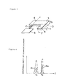
- Figure 5 is a perspective view illustrating how the optical scanner of this invention can direct a laser beam onto a screen;
- Figures 6(a), 6(b) and 6(c) show the traces made by a laser beam canned across a screen in each of three modes;
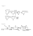
- Figure 7 is a block diagram of a drive circuit to power the drive source;
- Figure 8 is a block diagram of another example of a drive circuit to power the drive source;
- Figure 9 is a graph illustrating the relationship between the drive frequency of the vibrating element and the amplitude of vibration;
- Figure 10 is a perspective view of an example of an existing optical scanner;
- Figure 11 is a perspective view of another embodiment of this invention;
- Figure 12 is a diagram illustrating how the Figure 11 embodiment works;
- Figure 13 is a perspective view of another embodiment of this invention;
- Figure 14 is a diagram illustrating how the Figure 13 embodiment works;
- Figure 15 is a schematic drawing of a bar code reader which uses a bar code scanner of the invention;
- Figure 16 is a perspective view of the paths traced by a light beam when the beam is made to scan by the bar code scanner of Figure 15;
- Figures 17(a) and 17(b) are perspective views illustrating the situations in which the same bar code scanner might be used;
- Figure 18 shows another path traced by a light beam when the beam is made to scan by the same bar code scanner;
- Figures 19(a) and 19(b) are perspective views of situations which may occur when a laser beam is made to scan in the direction of a bar code by an existing laser-type bar code scanner; and
- Figure 20 shows a directional switch which may be used in the Figure 15 embodiment.
- Figure 1 shows an optical scanner in which a first embodiment this invention is implemented.
Optical scanner 1 is identical to the optical scanner described in Japanese Patent Application No. 2-209804, filed August 7, 1991. It consists of vibratingelement 7, which is formed of a single plate; andsmall drive source 6, which generates infinitesimal vibration in a piezoelectric or magnetostrictive actuator or the like. - The shape of
plate 7 is better illustrated in Figures 2 and 3.Deformable shaft 2 is long and narrow. Its lower end widens to formvibrator 5, which applies the oscillation produced bydrive source 6. Its upper end widens to form ascanning element 3, which causes a laser beam to scan.Deformable shaft 2 has two modes of elastic deformation. One is the twisting mode, in which the shaft rotates with respect to its axis P, as shown in Figure 2. The other is the bending mode, in which the shaft bends lengthwise along its axis P, as shown in Figure 3. The elastic vibration occurring in the twisting mode has a resonant frequency of fT, and that occurring in the bending mode has a resonant frequency of fB. -
Scanning element 3 is formed in such a way as to be imbalanced with respect to the center of balance P ofdeformable shaft 2. To insure this imbalance,weight unit 8 has been added off-center fromdeformable shaft 2. A weight unit is also placed above the upper end of theshaft 2.Scanning element 3 has amirror surface 4 to reflect a laser beam. This mirror surface may comprise the entirety ofscanning element 3 or only a part of it. In the embodiment shown in Figure 1, the mirror is positioned in the vicinity of the center of the shaft P. -
Vibrator 5 is glued or joined to the piezoelectric actuator or its equivalent device indrive source 6 and is thus fixed to the drive source.Scanning element 3 is freely supported bydeformable shaft 2. Drivesource 6, which employs a piezoelectric actuator or the like to induce high frequency vibration (for example, several hundred Hz) invibrator 5, is controlled by a drive circuit. This circuit excites vibration of resonant frequency fT in twisting mode and vibration of resonant frequency fB in bending mode. - Figure 7 shows an example of a
drive circuit 9. It comprises:oscillator 10, which continuously outputs a voltage signal of a frequency matching the resonant frequency fT of the twisting mode; amplifier 11, which amplifies the voltage signal output byoscillator 10;oscillator 12, which continuously outputs a voltage signal of a frequency matching the resonant frequency fB of the bending mode;amplifier 13, which amplifies the voltage signal output byoscillator 12; and switch 14, which switches between the output voltage of frequency fT from amplifier 11 and the output voltage of frequency fB fromamplifier 13, and applies one of these voltages to drivesource 6. Alternatively, switch 14 can be replaced by a mixing circuit which applies to drive source 6 a mixed signal having as components the voltage signal of frequency fT from amplifier 11 and that of frequency fB fromamplifier 13. Ifswitch 14 is placed betweenoscillators - Another
drive circuit 15, is shown in Figure 8. It comprisesvoltage reference unit 16, voltage/frequency converter 17 andamplifier 18. Voltage signal V1 (or V2) is output byvoltage reference unit 16 based on an entered drive shaft command signal, which, for example, is set at the operator's discretion. This voltage signal V1 (or V2) is converted to the corresponding signal of frequency fT (or fB) by voltage/frequency converter 17, and the converted signal is amplified byamplifier 18. The signal of resonant frequency fT (or fB) is then applied to drivesource 6. - In Figures 7 and 8, the frequency signal applied to drive
source 6 is pictured as a sine wave; however a rectangular or triangular wave can be used to yield the same result. - In operation, drive
source 6 is made to vibrate at a given frequency by the drive circuit, and this vibration is applied tovibrator 5. This vibrator will undergo reciprocating oscillation in direction x, as shown in Figure 1. Inertia acts onscanning element 3 to causeshaft 2 to elastically deform and vibrate in the direction in which force is applied. When the drive frequency f which is applied tovibrator 5 matches frequency fT, which characterizes the twisting mode, or frequency fB, which characterizes the bending mode, elastic vibration of the given mode will be amplified indeformable shaft 2, andscanning element 3 will be driven over a large angle of rotation. - The relationship between drive frequency f and angle of
rotation 8T ofscanning element 3, which obtains during twisting mode, or angle of rotation ΘB, which obtains during bending mode, is shown in Figure 4. This graph shows the relationship between the drive frequency f ofdrive source 6 and the angle of rotation ofscanning element 3 when the resonant frequency fT < fB. The horizontal axis is the drive frequency f, and the vertical axis is the angle ofrotation 8T of the scanning element in twisting mode or the angle ofrotation 8B of the same unit in bending mode. As can be seen, the angle of rotation ΘT, which obtains in twisting mode, reaches its maximum when the drive frequency f is equal to fT. The value of the angle drops off sharply on either side of the peak. The angle ofrotation 8B, which obtains in bending mode, reaches its maximum when the drive frequency f is equal to fB and drops off sharply on either side of the peak. Thus even drivesource 6, which is capable only of the infinitesimal vibration produced by a piezoelectric actuator, can causemirror surface 4 to rotate over a large angle by producing drive vibration of the same frequency as the resonant vibration characterizing each mode of elastic deformation. - The voltage applied to drive
source 6 can be adjusted while the drive frequency f which is applied bydrive source 6 tovibrator 5 is maintained at one of the possible resonant frequencies. In this way the amplitude x of the vibration ofvibrator 5 can be changed, and the angle ofrotation 8T or ΘB ofscanning element 3 can be controlled. In Figure 4, the dotted and solid lines show the amplitude of vibration ofvibrator 5, with the dotted line representing a greater amplitude. As the amplitude x of the vibration ofvibrator 5 increases, the angle ofrotation 8T or ΘB ofscanning element 3 also increases. - When
vibrator 5 is made to vibrate at resonant frequency fT in twisting mode, the torsional vibration is amplified in the deformable shaft, andscanning element 3 is made to rotate on its axis P over angle of rotation ΘT, as shown in Figure 2. If at this time laser beam a is made to strikemirror surface 4 as shown in Figure 1, the reflected laser beam a will scan over an angle of 2ΘT, which is twice the angle of rotation ΘT ofscanning element 3. Thus if laser beam a, reflected offoptical scanner 1, is made to strikescreen 19 as shown in Figure 5, it will scan to the left and right as shown in Figure 6 (a). - When
vibrator 5 is made to vibrate at resonant frequency fB in bending mode, the flexural vibration is amplified in the deformable shaft, andscanning element 3 is made to rotate around an axis Q, orthogonal to its axis P, over angle of rotation ΘB, as shown in Figure 3. If at this time laser beam a is made to strikemirror surface 4, the reflected laser beam a will scan over an angle of 2ΘB, which is twice the angle of rotation ΘB ofscanning element 3. Thus if laser beam a, reflected offoptical scanner 1, is made to strikescreen 19, it will scan up and down as shown in Figure 6 (b). - If
vibrator 5 is made to vibrate in a mode in which the two types of vibration are superposed, so that both resonant frequency fT of twisting mode and resonant frequency fB of bending mode are produced, both torsional and flexural vibration will be amplified indeformable shaft 2, andscanning element 3 will be made to vibrate over angle ofrotation 8T around axis P and over angle of rotation ΘB around axis Q. When laser beam a, reflected off scanningelement 3, strikesscreen 19, it will scan the entire surface, as shown in Figure 6 (c). - Thus the user can select one of the two orthogonal directions of scanning available in this optical scanner by selecting one of the resonant frequencies as the drive frequency of
drive source 6. The amplitude x of the vibration ofvibrator 5 can be adjusted by controlling the voltage applied to drivesource 6. In this way, the angle of scanning 28T or 2ΘB can be controlled. - In the optical scanner of this invention, the following improvements have been implemented in the scanner described above. Let us call the value of the turning rigidity of axis P (or the torsional rigidity) of deformable shaft 2 KT, and the rotational inertial moment of axis P in
scanning element 3 IT. The resonant frequency fT ofdeformable shaft 2 with respect to the twisting mode of deformation can then be determined byFormula 1, which is given below. -

- If we call the value of the turning rigidity of axis Q (or the flexural rigidity) of deformable shaft 2 KB, and the rotational inertial moment of axis Q in scanning element 3 IB, then the resonant frequency fB of
deformable shaft 2 with respect to the bending mode of deformation can be determined byFormula 2, which is given below.
- The rigidity values KT and KB are determined by the material and form chosen for
deformable shaft 2. Similarly, the rotational inertial moment values IT and IB are determined by the material and form ofscanning element 3. - In the first optical scanner of this invention, the shapes of
deformable shaft 2 andscanning element 3 are designed and the materials chosen in such a way as to prevent the resonant frequency fT of the twisting mode and the resonant frequency fB of the bending mode from being integral multiples of each other. To express this in concrete terms, resonant frequency fT is not allowed to be identical to any of the harmonic frequencies n˙ fB or fB/n of resonant frequency fB; and resonant frequency fB is not allowed to be identical to any of the harmonic frequencies n˙ fT or fT/n of resonant frequency fT, where n is an integer greater than or equal to 2. In other words, the deformable shaft and the scanning element are designed so as to uphold the following four rules simultaneously: - fT ≠ n˙fB
- fT ≠ fB/n
- fB ≠ n˙fT
- fB ≠ fT/n
- Of course, fT may not equal fB.
- As was discussed above, Figure 9 illustrates the fact that the vibrating element responds to drive frequencies n times greater than its resonant frequency fm (in this embodiment, fm stands for either fT or fB) and to
frequencies 1/n times as great (n is an integer which is greater than or equal to 2). The element will vibrate at an amplitude ranging from 1/2 or 1/3 to 1/20 or 1/30 the amplitude of vibration achieved when the drive frequency is equal to the resonant frequency fm. It follows, then, that a scanner designed will not experience parasitic vibration in, for example, the bending mode around axis Q when scanningelement 3 is being driven at resonant frequency fT to cause it to rotate around axis P. Such parasitic vibration would result if resonant frequency fT conformed to one of the harmonic frequencies n· fB or sub-harmonic frequencies fB/n of the bending mode of deformation. Conversely, vibration in the twisting mode will not be induced by interference between the modes while the element is being
made to vibrate in a bending mode. As a result, the light beam can be caused to scan in each axial direction with greater accuracy. - As can be seen clearly in Figure 9, the spectra of the harmonic frequency components are spread. This means that vibration will be generated in vibrating
element 7 at frequencies in the vicinity of the harmonic frequencies n· fT, fT/n, n· fB and fB/n. Consequently, if one wishes to completely eliminate interference between different modes of deformation, it will be necessary to completely remove any overlap among the resonant frequencies and harmonic frequencies, taking into account the spread of each frequency component into nearby spectral domains. - However, it has been determined experimentally that the overlap among the resonant frequencies and harmonics need not be completely eliminated. A sufficient result is obtained by shifting the value of every harmonic of the resonant frequency of each mode of vibration away from the resonant frequency of the other mode by at least 10% of the value of that resonant frequency. As an example, the harmonics n· fT and fT/n of twisting mode will be separated by 10% of the value of fB, the resonant frequency of bending mode. That is,

and
(n = 2, 3, ...) - Further, the harmonics n· fB and fB/n of the bending mode will be separated by 10% of the value of fT, the resonant frequency of the twisting mode. That is,

and
(n = 2, 3, ...) - The separation of frequencies can also be accomplished as follows. The resonant frequency of each mode of vibration can be shifted away from the harmonics of the other mode of vibration by at least 10% of its own value. If we use the embodiment as an example, the resonant frequency fT of twisting mode will be shifted away from the harmonics n· fB and fB/n of the bending mode by 10% of the value of the resonant frequency fB of the bending mode. That is,

and
(n = 2, 3, ...) - Further, the resonant frequency fB of bending mode will be shifted away from the harmonics n ' hand fT/n of twisting mode by 10% of the value of the resonant frequency fT oftwisting mode. That is,

and
(n = 2, 3, ...) - The value of 10% can also be computed as 10% of the value of any harmonic.
- Shifting the frequency in this way naturally results in the fact that it is impossible for the resonant frequencies fT and fB to overlap.
- The optical scanner of this invention is not limited to the form depicted in the embodiment described above. Various design changes are possible as long as the basic concept is not violated. For example, instead of using a piezoelectric or magnetostrictive actuator as the actuator for the drive source, any actuator capable of infinitesimal vibration at high speed may be used. One might, for example, use an actuator which produces infinitesimal vibration through the use of static electricity. The plate shown in the diagrams is one example of how the vibrating element might be formed. Any form is acceptable which renders the element capable of at least two modes of elastic deformation.
- The thus described embodiment of this invention eliminates interference vibration in another mode of vibration due to the harmonic content of vibration in the desired mode. As a result, the segregation of the various modes of vibration during scanning in a single mode is preserved; harmonics of another mode of vibration are prevented from occurring while the vibrating element is being driven at the resonant frequency of a given mode; and the accuracy of scanning is prevented from deteriorating.
- When the scanner is used in the optical scanning system of, for example, a laser printer, the print quality will be enhanced. This scanner, then, has the effect of improving the quality of any device in which it is employed.
- Another embodiment of this invention is shown in Figures 11-14.
- In this embodiment, the same reference num
bers are used to designate like parts in Figure 1. These like parts are not described again in detail. - In this second embodiment of the invention a
reflective mirror 45 is positioned facingmirror surface 4 and is fixed in place. - As with the first embodiment, drive
source 6 is made to vibrate at a given frequency a drive circuit, and this vibration is applied to vibratingelement 5. This vibrating element will undergo reciprocating oscillation in direction X, as shown in Figure 11. Inertia acts onscanning element 3 to causeshaft 2 to elastically deform and vibrate in the direction in which inertia is applied. Resonant frequency fT, which characterizes the twisting mode, and resonant frequency fB, which characterizes the bending mode, are determined by the modulus of elasticity, inertial moment, and other aspects ofdeformable shaft 2. When the drive frequency f which is applied to vibratingelement 5 matches one of these resonant frequencies, elastic vibration of the given mode will be amplified indeformable shaft 2, andscanning element 3 will rotate over a large angle of rotation. - Let us now assume, with reference to Figure 12, that laser beam a
strikes mirror surface 4 at point A. It is then reflected bymirror surface 4 and strikesreflective mirror 45 at point B, from which it is again reflected back to point C onmirror surface 4. If at this timedeformable shaft 2 is vibrated in either of the modes of deformation shown in Figure 11, for example, around axis P, scanningelement 3 will rotate over angle Δe. Laser beam a, reflected at point A offmirror surface 4, will be caused to scan over an angle which is twice the angle over which the scanning unit is rotating, or 2Δe. Laser beam a will thus scan over an angle 2Δθ when it is reflected offreflective mirror 45 at point B, and over an angle of 4Δθ when it is again reflected offmirror surface 4 at point C. In other words, a scanning angle can be achieved (4Δe) which is twice that obtained (2Δe) whenreflective mirror 45 is not employed. Thus the scanning angle can be amplified easily by the simple structural addition ofreflective mirror 45. - The
deformable shaft 2 is in the form of a narrow isthmus, as shown in Figures 1 and 11. Thus when the amplitude of vibration ofshaft 2 is greatly increased in order to widen the scanning angle, there is a danger that the shaft may be damaged. In the Figure 11 of the invention, the scanning angle is widened optically by the use of thereflective mirror 45, so the amplitude of vibration ofdeformable shaft 2 can be kept at an appropriate level. Thus the durability of this optical scanner is superior to that of existing scanners. - Although in Figure 12 laser beam a is reflected twice by
mirror surface 4, the concept is by no means limited to two reflections. If, for example, laser beam a is reflected three times bymirror surface 4 by way ofreflective mirror 45, a scanning angle of 4 x 2Δθ will be obtained. If it is reflected four times, the angle will be 8 x 2Δe. The number of times the beam is to be reflected can be designated as required. Thereflective mirror 45 can be supported in any manner which is convenient, such as by its own fixed support arm which may be connected to the back ofreflective mirror 45. A support configuration may be chosen which is appropriate for the conditions of use and other factors which may differ for different applications. The same applies to the materials used for the reflective mirror, its shape, the number of such mirrors to be used, and so on. - The reflective mirror may also be mounted to be moveable so that its position can be adjusted with respect to the mirror surface. By adjusting the position of the reflective mirror it is possible to change the direction of the axis of scanning (the direction in which the laser beam is travelling when the scanner is at rest). It is thus possible to adjust the direction of scanning without changing the position of the optical scanner. The effect, then, is that the optical axis can be adjusted.
- Figure 13 shows
optical scanner 46 in another embodiment of this invention. Inoptical scanner 46 like parts to those of Figures 1 and 11 bear the same part members. In this embodiment asemitransparent panel 47, which transmits one portion of laser beam a and reflects the other portion, is placed opposite themirror surface 4 ofscanning element 3. Light position detection element (PSD) 48 is placed in the path of the laser beam transmitted bysemitransparent panel 47. - Let us now assume that laser beam a has struck
mirror surface 4 at point A, as in Figure 14. Laser beam a is reflected by themirror surface 4 and strikessemitransparent panel 47, which is placed opposite the mirror surface, at point B. A portion of the laser beam, which we shall call monitor beam a2, is transmitted throughpanel 47 and strikes lightposition detection element 48. In this way the position of the light beam received bydetection element 48 is detected. The portion of laser beam a which strikessemitransparent panel 47 at point B and is reflected by it is again directed towardmirror surface 4, where it is again reflected at point C. If at this timedeformable shaft 2 is made to vibrate in either of its modes of deformation, as shown in Figure 6,scanning element 3 will rotate over an angle of Δe. Laser beam a, reflected bymirror surface 4 at point A, will scan over an angle twice as large as the angle of rotation ofscanning element 3, or 2Δe. This laser beam, reflected bysemitransparent panel 47 at joint B, and scanning over an angle of 2Δe, is again reflected bymirror surface 4 at point C. This re-reflected beam, which we shall call laser beam α1, will scan over an angle of 4Δe. In this way a wide angle of scanning can be achieved. The direction of travel of monitor beam a2, which has passed throughsemitransparent panel 47, changes over an angle of 2Δθ. The direction of travel of scanning beam α1, has a direct correspondence with that of the monitor beam. If the position of monitor beam a2 when it is received by lightposition detection element 48 is detected and the change in the position of the light received is output in the form of output voltage bydetection element 48, then the scanning position of laser beam a can be communicated as an electrical signal at the user's discretion. - In the Figure 13 embodiment, the light
position detection element 48 detects the light beam which had passes through thesemitransparent panel 47. However, the opposite configuration can also be adopted, i.e., using the light beam which has passed through thesemitransparent panel 47 as the scanning beam and that which has been reflected by thepanel 47 and again by themirror surface 4 as the monitor beam. In this case the reflected beam would be the one detected by the lightposition detection element 48. This configuration enables the light position detection element to magnify the changes in the position of the light it receives. It thus allows the system to detect the scanning position with great accuracy even if the light position detection element is placed quite close to the mirror surface. It also allows the scanner to be made more compact. - With the embodiment shown in Figures 13 and 14, the light reflected by the
semitransparent panel 47 could also be re-reflected by themirror surface 4 three or more times. In this case, the light transmitted by the panel could be obtained in several places. One of these locations would be chosen as the site for the light detection element. The shape of the semitransparent panel, its materials, its transmissivity, and so on, are not critical as long as it is capable of transmission and reflection. For thedevice 48 any detector may be selected which is capable of detecting the position of photoreception or the position of incidence of the light beam. This detector is not limited to a single light position detection element as a multisegmented photodiode, a charge coupled device (CCD) or some similar detector may also be used. Likewise, the position in which the light beam detection device is mounted, the direction it faces, and so on are not limited to those described above, but may be determined to suit the circumstances in which the scanner is to be used. - As with the earlier embodiments, the optical scanner of Figures 11-14 is not limited to the form particularly described above. Various design changes are possible as long as the basic concept is not violated. For example, the surface of the scanning element itself need not be fashioned into a mirror. A discrete mirror may instead be attached to the surface of the scanning element. The drive source in the embodiment used as an actuator a piezoelectric or magnetostrictive actuator; however, any actuator capable of infinitesimal vibration at high speed may be used. One might, for example, use an actuator which produces infinitesimal vibration through the use of static electricity. In the embodiment described above, the two resonant frequencies hand fB have two different values. These resonant frequencies can be set at the user's discretion by selecting values for the modulus of elasticity and inertial moment of the deformable shaft, by selecting the shape of the plate, and so on. Also, in the embodiments of Figures 11-14, the resonant frequencies hand fB may conform to each other, as well as being different as described in connection with the embodiments shown in Figures 1-9.
- The Figures 1-14 embodiments also feature an optical scanner in which a laser beam is caused to scan in two directions. However, an optical scanner of the type in which a light beam scans in a single direction, as disclosed in Japanese Patent Application No. 2-209804, filed August 7, 1991, may also be employed.
- The embodiment of the invention described in connection with Figures 11-14, enables the production of an ultracompact optical scanner in which it is possible to change the direction in which the light beam scans as well as the width of the area scanned (or the angle over which the beam scans). The angle over which the light beam scans can be amplified by means of the
reflective mirror 45. The angle of rotation of the deformable shaft can thus be increased by a factor of at least four, and the light beam can thus be made to scan over a large angle. - In addition, by using a
semitransparent panel 47 in place ofreflective mirror 45, a portion of the light beam is reflected while the remaining portion is transmitted through the panel. The beam can thus be split into a scanning component and a component which can be used to detect the scanning position. This design allows accurate position detection at any time in the region between the inception and completion of the scan. This scanner, then, can take the place of a highly accurate optical scanner with good repeatability and so enable the user to lower his costs. Moreover, as there is no need to curtail the effective scanning angle of the light beam, the range which the optical scanner is capable of covering can be utilized to its fullest. - Since the scanner described in connection with Figures 13 and 14 uses a light beam which has been reflected at least twice by a mirror surface for scanning, and the light transmitted by a semitransparent panel to detect the position of the light, it is thus capable of continuously monitoring the location of the scanning beam. This design also allows the angle over which the light beam scans to be increased. If, conversely, the light beam reflected at least twice by the
mirror surface 4 is used to detect the position of the scanning beam while the beam transmitted by thesemitransparent panel 47 is used for scanning, the accuracy and resolution of detecting the position of the beam can be increased. - Another embodiment of the invention, Figure 15 is a schematic drawing of
bar code reader 102, in which a hand-held bar code scanner contained within a manuallygraspable housing 101 is employed. The actual shape of the housing is not important. The bar code scanner may take any of the forms described above and illustrated in Figures 1, 11 or 13.Bar code reader 102 comprises the hand-held bar code scanner withinhousing 101; anddecoder 103, which decodes the bar code information using the signal output by the hand-held bar code scanner. - The bar code scanner within
housing 101 compriseslight source 104, which may be a semiconductor laser element or a light emitting diode (LED) to emit light beam a; alens 105, which focuses the light beam emitted bylight source 104 and causes it to strikeoptical scanner 106;optical scanner 106, which reflects light beam a after it is shaped bylens 105 and causes it to scan; andphotodetector element 108, which detects the amount of light that is reflected when light beam ascans bar code 107. - After light beam a is emitted by
light source 104, it is focussed and shaped bylens 105 and caused to strikeoptical scanner 106.Scanner 106 reflects light beam a while its reflective surface is moving, causing the light beam to scan. If at this time bar code (or bar code label) 107 is situated within thescanning range 0 covered by light beam a,photodetector element 108 will detect the amount of light reflected as light beam a scans the bar code. The difference in reflectivity between the lines and spaces inbar code 107 will be output byphotodetector element 108 as photoreception signal ;8, which will correspond to the pattern ofbar code 107.Decoder 103 will convert the signal representing the light detected byphotodetector element 108 into the information stored inbar code 107, i.e., numerals, symbols, or whatever. In this way it decodesbar code 107. - Figure 16 illustrates the operation of the bar code scanner contained in
housing 101. When a drive circuit causes drivesource 6 to vibrate at a frequency equal to resonant frequency fT of twisting mode,deformable shaft 13 undergoes torsional deformation, andscanning element 15 is made to rotate to the left and right over angle of rotation ΘT, as shown in Figure 16. If at this time light beam a is made to strikemirror surface 14 ofscanning element 3 as shown in Figure 16, the reflected laser beam a will scan left and right in plane X over an angle of 2ΘT. Thus ifbar code 107 is oriented sideways, as shown in Figure 17(a), the scanning of light beam a described above will enablebar code reader 102 to read the bar code. - When the drive circuit causes drive
source 6 to vibrate at a frequency equal to resonant frequency fB of bending mode,deformable shaft 13 undergoes flexural deformation, andscanning element 15 is made to rotate up and down over angle ofrotation 8B, as shown in Figure 16. If at this time light beam a is made to strikemirror surface 14 ofscanning element 3, the reflected light beam a will scan up and down over an angle of 2ΘB. Thus ifbar code 107 is oriented vertically, as shown in Figure 17(b), the scanning of light beam a described above will enablebar code reader 102 to read the bar code. - In this way the bar code scanner of this invention can cause light beam a to scan in two orthogonal planes (planes X and Y). It can therefore read
bar code 107 no matter whether the code is oriented horizontally, as shown in Figure 17(a), or vertically, as in 17(b). This invention thus obviates the need to reposition the product whose bar code is being scanned or reorient thehousing 101 of the bar code scanner, a problem experienced with existing scanners. The bar code scanner withinhousing 101 is also furnished with adirectional switch 14, as shown in Figure 7, which enables the operator easily to change the direction or plane of scanning. As shown in Figure 20, a switching circuit may also be provided for the scanning direction which switches the scanning direction automatically at short intervals by simply operatingswitch 14 with the output of alow frequency oscillator 110. This circuit enablesbar code 107 to be read automatically no matter what its orientation. Further, if a signal from the drive circuit is applied to drivesource 6 in which a signal of resonant frequency fT of twisting mode and a signal of resonant frequency fB of bending mode are superposed, then drivesource 12 will causevibrational input element 14 to vibrate in a mode in which the two types of vibration are superposed. Both torsional and flexural vibration will be amplified indeformable shaft 13, andscanning element 15 will be made to vibrate over angle ofrotation 8T around axis P and over angle ofrotation 8B around axis Q. Light beam a will be made to scan in two dimensions. The track which this two- dimensional scan will follow is determined by the ratio ofrotational angle 8T to rotational angle ΘB. For example, Figure 18 shows the track αT scanned by the light beam when the ratio ofrotational angle 8T of twisting mode torotational angle 8B of bending mode is 1:1. In this case, the track αT followed by the light beam describes a Lissajous figure. The track here is inclined 45 from both the horizontal plane X and the vertical plane Y. If this two-dimensional scan is combined with scans of the X and Y planes, by, for example, automatically switching among the resonant frequencies fT, fB and fT + fB, the scanner will be able to read the information inbar code 107 in virtually any way it may be oriented. In the example pictured in Figure 18, the ratio of 8T to 8B was 1:1; however, this ratio may assume other proportions. - The bar code scanner of this invention can employ a built-in two-axis optical scanner which is quite compact and light. This
scanner housing 101 can be as small as 15mm x 15mm x 10mm and it can weigh less than 5 grams. - Consequently, the bar code scanner, too, can be made small and lightweight. Unlike the stationary multi-axis bar code scanners which can be found in supermarkets, this bar code scanner is especially useful as a hand-held scanner. The operator can easily hold the
scanner housing 101 in his hand to read the bar code. - With the Figure 15 embodiment of the invention, a light beam can be scanned along a bar code even if the code is tilted with respect to the scanner. In this way a tilted bar code can be read. Consequently, there is no need to reposition the bar code or reorient the bar code scanner. Bar codes can be read quickly and the nuisance factor for the operator is reduced.
- Further, as the optical scanner used is smaller and lighter than a conventional polygonal mirror and a servomotor, the bar code scanner itself can assume a more compact and lightweight form. As a result, a small, light, hand-held bar code scanner can be produced. This hand-held scanner is capable of scanning along multiple axes, a function which in the past could be found only in stationary scanners.
- While several embodiments of the invention and variants thereof have been described and illustrated, many modifications can be made to the invention without departing from its spirit and scope. Accordingly, the invention is not limited to the foregoing description, but is only limited by the scope of the appended claims.
where (n = 2, 3, ...)
Claims (22)
Applications Claiming Priority (6)
| Application Number | Priority Date | Filing Date | Title |
|---|---|---|---|
| JP41341/91 | 1991-02-12 | ||
| JP4134191A JP2981576B2 (en) | 1991-02-12 | 1991-02-12 | Optical scanner |
| JP138307/91 | 1991-05-13 | ||
| JP3138307A JP2981579B2 (en) | 1991-05-13 | 1991-05-13 | Optical scanner |
| JP298235/91 | 1991-10-16 | ||
| JP3298235A JP2917624B2 (en) | 1991-10-16 | 1991-10-16 | Barcode scanner |
Publications (3)
| Publication Number | Publication Date |
|---|---|
| EP0499236A2 true EP0499236A2 (en) | 1992-08-19 |
| EP0499236A3 EP0499236A3 (en) | 1993-06-16 |
| EP0499236B1 EP0499236B1 (en) | 1997-05-28 |
Family
ID=27290786
Family Applications (1)
| Application Number | Title | Priority Date | Filing Date |
|---|---|---|---|
| EP92102340A Expired - Lifetime EP0499236B1 (en) | 1991-02-12 | 1992-02-12 | Improved optical scanner and bar code reader employing same |
Country Status (4)
| Country | Link |
|---|---|
| US (1) | US5828051A (en) |
| EP (1) | EP0499236B1 (en) |
| AT (1) | ATE153789T1 (en) |
| DE (1) | DE69219920T2 (en) |
Cited By (1)
| Publication number | Priority date | Publication date | Assignee | Title |
|---|---|---|---|---|
| CN110937318A (en) * | 2019-11-28 | 2020-03-31 | 盐城市盐渎西城贸易有限公司 | Accurate scanning and identifying device for cargo bar codes |
Families Citing this family (11)
| Publication number | Priority date | Publication date | Assignee | Title |
|---|---|---|---|---|
| JPH11184960A (en) * | 1997-10-16 | 1999-07-09 | Tohoku Ricoh Co Ltd | Bar code reader |
| WO2001080163A1 (en) * | 2000-04-18 | 2001-10-25 | Metrologic Instruments, Inc. | Bioptical holographic laser scanning system |
| JP2003099704A (en) * | 2001-09-21 | 2003-04-04 | Mitsubishi Electric Corp | Handy terminal device with programmable vibration pattern, and application software for handy terminal device |
| US6676020B2 (en) * | 2001-11-30 | 2004-01-13 | Hewlett-Packard Development Company, L.P. | Radiation director apparatus and method using piezoelectric movement |
| JP4691704B2 (en) * | 2005-04-13 | 2011-06-01 | 独立行政法人産業技術総合研究所 | Optical scanning device |
| US7573625B2 (en) * | 2005-07-07 | 2009-08-11 | Lexmark International, Inc. | Multiharmonic galvanometric scanning device |
| WO2008038649A1 (en) | 2006-09-27 | 2008-04-03 | National Institute Of Advanced Industrial Science And Technology | Optical scanning device |
| US7709800B2 (en) * | 2006-12-27 | 2010-05-04 | Nucsafe, Inc. | Method and apparatus for rejecting radioactive interference in a radiation monitoring station |
| EP2423730A4 (en) * | 2009-04-21 | 2014-09-17 | Konica Minolta Opto Inc | Scanning optical system and projector provided with the same |
| US8964183B2 (en) * | 2012-05-31 | 2015-02-24 | General Electric Company | Systems and methods for screening of biological samples |
| KR20220031996A (en) * | 2019-07-10 | 2022-03-15 | 하마마츠 포토닉스 가부시키가이샤 | Semiconductor device inspection method and semiconductor device inspection apparatus |
Citations (9)
| Publication number | Priority date | Publication date | Assignee | Title |
|---|---|---|---|---|
| US3666974A (en) * | 1970-01-16 | 1972-05-30 | Bulova Watch Co Inc | Torsional fork transducers |
| US4213146A (en) * | 1978-03-24 | 1980-07-15 | Laser Video, Inc. | Scanning system for light beam displays |
| EP0214863A2 (en) * | 1985-09-06 | 1987-03-18 | Citizen Watch Co. Ltd. | Light beam scanning apparatus |
| EP0223535A2 (en) * | 1985-11-14 | 1987-05-27 | Xerox Corporation | Piezoelectric laser scanner |
| SU1448328A1 (en) * | 1986-07-23 | 1988-12-30 | Институт Технической Кибернетики Ан Бсср | Two-coordinate light deflector |
| SU1485188A1 (en) * | 1987-08-14 | 1989-06-07 | Tom Elektrotekhnicheskij Z | Angular deviation device |
| DE3833260A1 (en) * | 1987-12-03 | 1989-06-15 | Jenoptik Jena Gmbh | Light-deflecting device |
| JPH0254212A (en) * | 1988-08-19 | 1990-02-23 | Nec Corp | Optical scanner |
| EP0471291A2 (en) * | 1990-08-07 | 1992-02-19 | Omron Corporation | Optical scanner |
Family Cites Families (9)
| Publication number | Priority date | Publication date | Assignee | Title |
|---|---|---|---|---|
| US3921045A (en) * | 1974-07-24 | 1975-11-18 | Bulova Watch Co Inc | Damped torsional rod oscillator |
| US3998092A (en) * | 1974-12-23 | 1976-12-21 | Bruce Sargent Maccabee | Simple systems for light beam modulation by acoustic surface waves |
| US4732440A (en) * | 1985-10-22 | 1988-03-22 | Gadhok Jagmohan S | Self resonant scanning device |
| US5170277A (en) * | 1988-05-11 | 1992-12-08 | Symbol Technologies, Inc. | Piezoelectric beam deflector |
| US4902083A (en) * | 1988-05-31 | 1990-02-20 | Reflection Technology, Inc. | Low vibration resonant scanning unit for miniature optical display apparatus |
| US4919500A (en) * | 1988-09-09 | 1990-04-24 | General Scanning, Inc. | Torsion bar scanner with damping |
| US5168149A (en) * | 1989-10-30 | 1992-12-01 | Symbol Technologies, Inc. | Scan pattern generators for bar code symbol readers |
| US5132524A (en) * | 1990-05-21 | 1992-07-21 | Lazerdata Corporation | Multi directional laser scanner |
| US5079641A (en) * | 1990-09-17 | 1992-01-07 | Eastman Kodak Company | Assembly for static control and dynamic damping of an optical element |
-
1992
- 1992-02-11 US US07/833,664 patent/US5828051A/en not_active Expired - Fee Related
- 1992-02-12 AT AT92102340T patent/ATE153789T1/en not_active IP Right Cessation
- 1992-02-12 DE DE69219920T patent/DE69219920T2/en not_active Expired - Fee Related
- 1992-02-12 EP EP92102340A patent/EP0499236B1/en not_active Expired - Lifetime
Patent Citations (9)
| Publication number | Priority date | Publication date | Assignee | Title |
|---|---|---|---|---|
| US3666974A (en) * | 1970-01-16 | 1972-05-30 | Bulova Watch Co Inc | Torsional fork transducers |
| US4213146A (en) * | 1978-03-24 | 1980-07-15 | Laser Video, Inc. | Scanning system for light beam displays |
| EP0214863A2 (en) * | 1985-09-06 | 1987-03-18 | Citizen Watch Co. Ltd. | Light beam scanning apparatus |
| EP0223535A2 (en) * | 1985-11-14 | 1987-05-27 | Xerox Corporation | Piezoelectric laser scanner |
| SU1448328A1 (en) * | 1986-07-23 | 1988-12-30 | Институт Технической Кибернетики Ан Бсср | Two-coordinate light deflector |
| SU1485188A1 (en) * | 1987-08-14 | 1989-06-07 | Tom Elektrotekhnicheskij Z | Angular deviation device |
| DE3833260A1 (en) * | 1987-12-03 | 1989-06-15 | Jenoptik Jena Gmbh | Light-deflecting device |
| JPH0254212A (en) * | 1988-08-19 | 1990-02-23 | Nec Corp | Optical scanner |
| EP0471291A2 (en) * | 1990-08-07 | 1992-02-19 | Omron Corporation | Optical scanner |
Non-Patent Citations (2)
| Title |
|---|
| DATABASE WPIL Week 8940, Derwent Publications Ltd., London, GB; AN 89-291939 & SU-A-1 448 328 (AS BELO TECH CYBERNETICS) 30 December 1988 * |
| DATABASE WPIL Week 8950, Derwent Publications Ltd., London, GB; AN 89-369379 & SU-A-1 485 188 (TOMSK ELECTROTEC WK) 7 June 1989 * |
Cited By (1)
| Publication number | Priority date | Publication date | Assignee | Title |
|---|---|---|---|---|
| CN110937318A (en) * | 2019-11-28 | 2020-03-31 | 盐城市盐渎西城贸易有限公司 | Accurate scanning and identifying device for cargo bar codes |
Also Published As
| Publication number | Publication date |
|---|---|
| EP0499236A3 (en) | 1993-06-16 |
| DE69219920T2 (en) | 1998-01-29 |
| DE69219920D1 (en) | 1997-07-03 |
| EP0499236B1 (en) | 1997-05-28 |
| ATE153789T1 (en) | 1997-06-15 |
| US5828051A (en) | 1998-10-27 |
Similar Documents
| Publication | Publication Date | Title |
|---|---|---|
| EP0471291B1 (en) | Optical scanner | |
| US5828051A (en) | Optical scanner and bar code reader employing same | |
| EP0456095B1 (en) | Scanning arrangement | |
| US5581070A (en) | Omni-directional scan pattern generator in electro-optical scanners | |
| US5525791A (en) | Mirrorless scanners with movable laser, optical and sensor components | |
| EP1794702B1 (en) | Monitoring light beam position in electro-optical readers and image projectors | |
| EP0742530A2 (en) | Mirrorless scanners with movable laser, optical and sensor components | |
| EP0295863B1 (en) | Optical printer of scanning type | |
| JPH06236450A (en) | Fine scanning module provided with exchangeable x-y scanning element | |
| JPH10221073A (en) | Position-detecting survey machine | |
| JP2008517307A5 (en) | ||
| US7182262B2 (en) | Inertial drive scanning arrangement and method | |
| JP5065116B2 (en) | Oscillator device, optical deflection device, and control method thereof | |
| JP2017097203A (en) | Optical scanning device | |
| JP2917624B2 (en) | Barcode scanner | |
| JP2995835B2 (en) | Area photoelectric sensor | |
| JPH04368907A (en) | Optical scanner | |
| EP0626605B1 (en) | Vibrating and rotating optical scanning device | |
| KR100239340B1 (en) | Laser scanning apparatus for laser printer | |
| JP3016101B2 (en) | Sheet size sensor | |
| JPH06139387A (en) | Optical reader | |
| JP2995836B2 (en) | Optical scanning device | |
| JP2981576B2 (en) | Optical scanner | |
| JP3620914B2 (en) | Scanning device | |
| JP2002107653A (en) | Electronic equipment with ultrasonic motor |
Legal Events
| Date | Code | Title | Description |
|---|---|---|---|
| PUAI | Public reference made under article 153(3) epc to a published international application that has entered the european phase |
Free format text: ORIGINAL CODE: 0009012 |
|
| 17P | Request for examination filed |
Effective date: 19920309 |
|
| AK | Designated contracting states |
Kind code of ref document: A2 Designated state(s): AT BE CH DE DK ES FR GB GR IT LI MC NL PT SE |
|
| RBV | Designated contracting states (corrected) |
Designated state(s): AT BE CH DE DK ES FR GB GR IT LI MC NL SE |
|
| PUAL | Search report despatched |
Free format text: ORIGINAL CODE: 0009013 |
|
| AK | Designated contracting states |
Kind code of ref document: A3 Designated state(s): AT BE CH DE DK ES FR GB GR IT LI MC NL PT SE |
|
| 17Q | First examination report despatched |
Effective date: 19950920 |
|
| GRAG | Despatch of communication of intention to grant |
Free format text: ORIGINAL CODE: EPIDOS AGRA |
|
| GRAH | Despatch of communication of intention to grant a patent |
Free format text: ORIGINAL CODE: EPIDOS IGRA |
|
| GRAH | Despatch of communication of intention to grant a patent |
Free format text: ORIGINAL CODE: EPIDOS IGRA |
|
| GRAA | (expected) grant |
Free format text: ORIGINAL CODE: 0009210 |
|
| AK | Designated contracting states |
Kind code of ref document: B1 Designated state(s): AT BE CH DE DK ES FR GB GR IT LI MC NL SE |
|
| PG25 | Lapsed in a contracting state [announced via postgrant information from national office to epo] |
Ref country code: IT Free format text: LAPSE BECAUSE OF FAILURE TO SUBMIT A TRANSLATION OF THE DESCRIPTION OR TO PAY THE FEE WITHIN THE PRE;WARNING: LAPSES OF ITALIAN PATENTS WITH EFFECTIVE DATE BEFORE 2007 MAY HAVE OCCURRED AT ANY TIME BEFORE 2007. THE CORRECT EFFECTIVE DATE MAY BE DIFFERENT FROM THE ONE RECORDED.SCRIBED TIME-LIMIT Effective date: 19970528 Ref country code: FR Effective date: 19970528 Ref country code: ES Free format text: THE PATENT HAS BEEN ANNULLED BY A DECISION OF A NATIONAL AUTHORITY Effective date: 19970528 Ref country code: NL Free format text: LAPSE BECAUSE OF FAILURE TO SUBMIT A TRANSLATION OF THE DESCRIPTION OR TO PAY THE FEE WITHIN THE PRESCRIBED TIME-LIMIT Effective date: 19970528 Ref country code: BE Effective date: 19970528 Ref country code: AT Effective date: 19970528 Ref country code: CH Effective date: 19970528 Ref country code: GR Free format text: LAPSE BECAUSE OF FAILURE TO SUBMIT A TRANSLATION OF THE DESCRIPTION OR TO PAY THE FEE WITHIN THE PRESCRIBED TIME-LIMIT Effective date: 19970528 Ref country code: DK Effective date: 19970528 Ref country code: LI Effective date: 19970528 |
|
| REF | Corresponds to: |
Ref document number: 153789 Country of ref document: AT Date of ref document: 19970615 Kind code of ref document: T |
|
| REG | Reference to a national code |
Ref country code: CH Ref legal event code: EP |
|
| REF | Corresponds to: |
Ref document number: 69219920 Country of ref document: DE Date of ref document: 19970703 |
|
| PG25 | Lapsed in a contracting state [announced via postgrant information from national office to epo] |
Ref country code: SE Effective date: 19970828 |
|
| EN | Fr: translation not filed | ||
| NLV1 | Nl: lapsed or annulled due to failure to fulfill the requirements of art. 29p and 29m of the patents act | ||
| REG | Reference to a national code |
Ref country code: CH Ref legal event code: PL |
|
| PG25 | Lapsed in a contracting state [announced via postgrant information from national office to epo] |
Ref country code: GB Free format text: LAPSE BECAUSE OF NON-PAYMENT OF DUE FEES Effective date: 19980212 |
|
| PLBE | No opposition filed within time limit |
Free format text: ORIGINAL CODE: 0009261 |
|
| STAA | Information on the status of an ep patent application or granted ep patent |
Free format text: STATUS: NO OPPOSITION FILED WITHIN TIME LIMIT |
|
| 26N | No opposition filed | ||
| PG25 | Lapsed in a contracting state [announced via postgrant information from national office to epo] |
Ref country code: MC Free format text: LAPSE BECAUSE OF NON-PAYMENT OF DUE FEES Effective date: 19980831 |
|
| GBPC | Gb: european patent ceased through non-payment of renewal fee |
Effective date: 19980212 |
|
| PGFP | Annual fee paid to national office [announced via postgrant information from national office to epo] |
Ref country code: DE Payment date: 20090227 Year of fee payment: 18 |
|
| PG25 | Lapsed in a contracting state [announced via postgrant information from national office to epo] |
Ref country code: DE Free format text: LAPSE BECAUSE OF NON-PAYMENT OF DUE FEES Effective date: 20100901 |
|
| REG | Reference to a national code |
Ref country code: DE Ref legal event code: R082 Ref document number: 69219920 Country of ref document: DE Representative=s name: KILIAN KILIAN & PARTNER, DE |