EP0499754A1 - Closure for securely fixing an electrical cable to an opening and protective cable sleeve comprising such closures - Google Patents
Closure for securely fixing an electrical cable to an opening and protective cable sleeve comprising such closures Download PDFInfo
- Publication number
- EP0499754A1 EP0499754A1 EP91400364A EP91400364A EP0499754A1 EP 0499754 A1 EP0499754 A1 EP 0499754A1 EP 91400364 A EP91400364 A EP 91400364A EP 91400364 A EP91400364 A EP 91400364A EP 0499754 A1 EP0499754 A1 EP 0499754A1
- Authority
- EP
- European Patent Office
- Prior art keywords
- sleeve
- hollow body
- cable
- intended
- plug
- Prior art date
- Legal status (The legal status is an assumption and is not a legal conclusion. Google has not performed a legal analysis and makes no representation as to the accuracy of the status listed.)
- Granted
Links
- 230000001681 protective effect Effects 0.000 title claims description 3
- 239000003566 sealing material Substances 0.000 claims abstract description 10
- 238000007789 sealing Methods 0.000 claims description 5
- 230000000295 complement effect Effects 0.000 claims description 4
- 239000011347 resin Substances 0.000 claims description 4
- 229920005989 resin Polymers 0.000 claims description 4
- 230000000717 retained effect Effects 0.000 claims description 4
- 239000000463 material Substances 0.000 claims description 2
- 238000005070 sampling Methods 0.000 claims description 2
- 238000002347 injection Methods 0.000 claims 1
- 239000007924 injection Substances 0.000 claims 1
- 239000004033 plastic Substances 0.000 description 3
- 229920003023 plastic Polymers 0.000 description 3
- 238000000034 method Methods 0.000 description 2
- 239000000565 sealant Substances 0.000 description 2
- 229920005830 Polyurethane Foam Polymers 0.000 description 1
- 238000004026 adhesive bonding Methods 0.000 description 1
- 239000000428 dust Substances 0.000 description 1
- 239000011496 polyurethane foam Substances 0.000 description 1
Images


Classifications
-
- H—ELECTRICITY
- H02—GENERATION; CONVERSION OR DISTRIBUTION OF ELECTRIC POWER
- H02G—INSTALLATION OF ELECTRIC CABLES OR LINES, OR OF COMBINED OPTICAL AND ELECTRIC CABLES OR LINES
- H02G15/00—Cable fittings
- H02G15/08—Cable junctions
- H02G15/18—Cable junctions protected by sleeves, e.g. for communication cable
- H02G15/192—Cable junctions protected by sleeves, e.g. for communication cable with support means for ends of the sleeves
-
- H—ELECTRICITY
- H02—GENERATION; CONVERSION OR DISTRIBUTION OF ELECTRIC POWER
- H02G—INSTALLATION OF ELECTRIC CABLES OR LINES, OR OF COMBINED OPTICAL AND ELECTRIC CABLES OR LINES
- H02G15/00—Cable fittings
- H02G15/013—Sealing means for cable inlets
Definitions
- the present invention relates to a plug for sealingly fixing an electric or telephone cable to a circular opening for the passage of said cable.
- This tip is intended to be filled with a sealing material such as polyurethane foam. Experience has shown that the seal thus obtained was not always sufficient.
- the object of the present invention is to remedy the drawbacks of the above-mentioned embodiment, by creating a plug making it possible to tightly fix an electric or telephone cable to a circular opening for the passage of said cable, this plug ensuring perfect tightness with respect to the opening and the cable, perfect axial fixing of the cable to the opening and this plug which can be easily removed from the latter to replace the cable.
- the two jaws provide excellent axial fixing of the cable relative to the plug since the openings of these jaws are clamped on the cable during the assembly of the two shells of the hollow body.
- the sealing material filling the chamber between the two jaws and surrounding the cable ensures excellent sealing between this cable and the plug.
- the plug since the plug is removably attached to the cable passage opening, it can be easily removed from this opening to replace the cable.
- the plug intended to be fixed to the end of a cable passage tube further comprises a sleeve intended to be introduced into said end of the tube and the outside diameter of which corresponds to the diameter inside said tube, this sleeve having all around one of its ends means for removably fixing it to one end of the hollow body.
- the sleeve has at its end a flange and the hollow body comprises at its adjacent end an annular groove shaped to engage on said collar of the sleeve.
- the sleeve has inside a cover which completely seals it, this cover being connected to the internal face of the sleeve by a thinned and frangible annular zone making it possible to tear off this cover to pass the cable.
- the cover of the sleeve seals the end of the tube, so that moisture cannot penetrate therein.
- To pass the cable through the tube simply remove the seal, fix the plug around the cable, inject a sealant into the plug and then fix it at the end of the tube.
- the plug intended to be fixed in an end piece of circular section projecting from a wall has the particularity that the hollow body comprises on its external surface at least two annular grooves each receiving an O-ring intended sealing between the outer surface of the hollow body and the inner surface of said tip.
- the hollow body comprises near one of its ends a flange intended to bear against the free end of the end piece and near its other end an annular groove intended to receive a key in the form of an arc of circle intended to removably lock the hollow body against the inner face of said wall.
- Said flange and said key thus axially lock the plug to the end piece, in a manner which is easily removable.
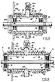
- FIG. 1 there is shown a plug 1 surrounding a telephone cable extending in a tube 3 for example buried.
- This plug 1 is tightly fixed to the end 4 having a circular opening of the tube 3.
- the plug 1 comprises a substantially cylindrical hollow body 5 constituted by two plastic shells 5a, 5b (see FIGS. 2 and 3) fixed around the cable 2 and comprising two jaws 6, 7 retained radially in grooves 8, 9 formed in said body and each comprising a central opening 10, 11 for passage of the cable 2. These central openings 10, 11 bear radially on the cable 2 during the fixing by tightening of the two shells 5a , 5b one on top of the other.
- the two jaws 6, 7 define between them a chamber 12 surrounding the cable 2 and filled with a sealing material which is injected into this chamber 12 through an opening 13 made in the wall of the body 5. Furthermore, the hollow body 5 is fixed in a removable and leaktight manner to the circular opening 4 for passage of the cable 2 in the tube 3.
- the jaws 6 and 7 have been described in particular in French patent 2,582,854 of the applicant. They are made of plastic and have annular grooves which give them a radial elasticity which makes it possible to produce a seal between the openings 10 and 11 of these jaws 6, 7 and the outer surface of the cable.
- the plug 1 further comprises a plastic sleeve 14 engaged in the end 4 of the tube 3 and whose outer diameter corresponds to the inner diameter of this tube 3.
- the sealed connection between the sleeve 14 and the internal surface of the tube 3 is provided by gluing.
- This sleeve 14 includes means around its end for removably fixing it to the adjacent end of the hollow body 5.
- the sleeve 14 has for this purpose, at its end, a flange 15 and the hollow body 5 comprises at its adjacent end an annular groove 16 shaped to engage on the flange 15 of the sleeve 14. Furthermore, a seal 17 is provided between the annular groove 16 and the flange 15. In addition, the sleeve 14 comprises behind its flange 15 a second flange 18 which bears against the end 4 of the cable passage tube 3 2. The two flanges 15 and 18 define between them an annular space 19 in which is engaged the end edge 20 of the hollow body 5 adjacent to the annular groove 16.
- the sleeve 14 has inside a cover 21 (dotted line) which completely blocks it (when the tube 3 is not crossed by a cable), this cover 21 being connected to the internal face of the sleeve 14 by a frangible thinned annular zone 22 making it possible to remove this cover 21 to pass the cable 2 through the tube 3.
- the two shells 5a, 5b of the hollow body 5 comprise on each side two projecting parts 23a, 23b bearing on one another and each provided with an inclined ramp 24a, 24b relative to the contact plane P of the two projecting parts 23a, 23b.
- These ramps 24a, 24b are associated with an assembly member 25 of section substantially in C comprising two counter-ramps 25a, 25b complementary to the ramps 24a, 24b of the two projecting parts and being able to engage by force on the latter to tighten the two parts projecting one over the other.
- Figure 2 also shows that a seal is provided between the projecting portions 23a and 23b.
- the procedure is as follows. It will be assumed that the sleeve 14 is already in place at the end 4 of the tube. This sleeve 14 seals the end of the tube 3, which preserves the interior of the latter against humidity and dust. For put the cable 2 in the tube 3, simply remove the cover 21 by pulling on the tab 21a to tear it off according to the circular area 22 adjacent to the internal surface of the sleeve 14, after which we can engage the cable 2 in tube 3.
- a sealing material is injected into the opening 13 of the plug, to fill the chamber 12 between the jaws 6, 7 and which surrounds the cable 2.
- FIGS. 4 and 5 show a plug 30 intended to be fixed as indicated in FIG. 6 in a nozzle 31 of circular section projecting from a wall 32.
- the plug 30 is of cylindrical shape and comprises two shells 33a, 33b (see FIG. 5) assembled one on the other by means of screws 34.
- the cylindrical hollow body defined by the two shells 33a, 33b comprises inside its two jaws 35, 36 identical to the jaws 6, 7 of the embodiment according to Figures 1 to 3 extending radially and bearing elastically on the cable 2.
- These jaws 35, 36 define between them a chamber 37 intended to be filled with a sealing material.
- the cylindrical hollow body 30 comprises on its external surface two annular grooves 38, 39 each receiving an O-ring 40, 41 sealing between the external surface of the hollow body 30 and the internal cylindrical surface 31a of the end piece 31.
- the hollow body 30 comprises near its end 42 a flange 43 bearing against the free end 31b of the end piece 31 and near its other end 44 an annular groove 45 receiving a key or elastic ring in the form of an arc of a circle 46 making it possible to removably lock the hollow body 30 against the internal face 32a of the wall 32.
- the external surface of the hollow body 30 has, between the two grooves 38, 39 provided for receiving a seal 40, 41, an annular recess 47 which communicates through an orifice 48 with the internal chamber 37 between the two jaws 35, 36.
- the end piece 31 also has an orifice 49 for injecting a sealing material intended to fill the annular recess 47 and the chamber 37.
- the plug 30 is then locked against the wall 32 by engaging the ring 46 in the groove 45.
- a sealant is injected into the opening 49 of the plug 30 which fills the recess 47 between the plug and the inner face of the end piece 31 as well as the chamber 37.
- the plug 30 can be removed from the end piece 31 to remove the cable and replace it with a new cable or one with a different diameter.
- the plug 50 differs from the version shown in FIG. 1.
- the sleeve 51 comprises on its outer surface engaged in the tube 3 for passing the cable 2, a series of annular grooves 52. These grooves 52 have a longitudinal sawtooth section. These facilitate the bonding of the sleeve 51 in the tube 3.
- the sleeve 51 is constituted by two half-shells assembled along a plane passing through its axis.
- the sleeve 51 comprises, near the flange 54, an opening 55 for passage comprising a connector 56 allowing the screwing of a gas sampling valve (not shown). We can thus detect the possible presence of gas in the tube 3 and eliminate it by suction.
- the plugs 60, 61 are fixed in a nozzle 62 of circular section projecting from a wall 63 constituting the end wall of a sleeve for protecting the splice of one or multiple cables.
- the hollow body 64, 65 has a smooth exterior surface 66, the diameter of which corresponds to the interior diameter of the endpiece 62.
- the inner surface of the end piece 64, 65 comprises at least two annular grooves 67 of section rectangular each receiving a seal 68 of complementary section made of flexible material for sealing between the external surface 66 of the hollow body 64, 65 and the internal surface of the endpiece 62.
- the hollow body 64 is constituted by two half-shells 64a, 64b assembled along a plane passing through the axis XX 'of the hollow body. These two half-shells 64a, 64b are tightened one on the other by means of screws 69 placed at the two opposite ends of the hollow body 64.
- the hollow body 65 is constituted by a tubular body in one piece comprising near each of its ends an annular groove 70. These ends of the body 65 are each provided with a jaw holder 71 in two parts 71a, 71b assembled one against the other perpendicular to the axis XX 'of the tubular body 65 by means of clamping screws 69.
- Each jaw holder 79 has on its edge adjacent to the tubular body 65 a groove 80 in an arc directed towards the axis XX 'of the body 65 and engaged in the annular groove 70 of this body.
- the two grooves 80 in an arc form a continuous circular groove when the two parts 71a, 71b of the jaw holder 70 are assembled one against the other, as shown in FIG. 9.
- the wall 63 is the end wall of a sleeve for protecting the splicing of electric cables 2.
- This sleeve comprises two half-shells 63a, 63b assembled one on the other along a plane passing through the 'axis XX' of the sleeve.
- Each end wall 63 of said sleeve comprises at least one end piece 62 of circular section projecting towards the inside of the sleeve and receiving a plug 60 or 61.
- each tip 62 is in two parts 62a, 62b.
- Each end part 62, 62a is molded in one piece with the other end part and is assembled one on the other according to the assembly plane of the two half-shells 63a, 63b of the sleeve which passes through the axis XX '.
- each plug 60, 61 has two diametrically opposite tubular protrusions 81, 82. Each of these protrusions is engaged in an opening 83, 84 made in the part 62a, 62b of the corresponding tip.
- the two tubular protrusions 81, 82 consist respectively of a conduit 81 for injecting resin inside the hollow body 64, 65 and a conduit 82 in which is slidably mounted a piston 83a provided with a rod 84a which can project outside the duct to indicate the filling level of the resin.
- the half-shell 63b carries for this purpose three end pieces such as 62b in which are housed three plugs 61, 61a, 61b. These three plugs 61, 61a, 61b are trapped inside the sleeve after the upper half-shell (not shown in FIG. 10) has been placed on the lower half-shell 63b.
Abstract
Description
La présente invention concerne un bouchon permettant de fixer de façon étanche un câble électrique ou téléphonique à une ouverture circulaire de passage dudit câble.The present invention relates to a plug for sealingly fixing an electric or telephone cable to a circular opening for the passage of said cable.
On a déjà décrit par exemple dans le brevet français2 466 887 de la demanderesse, un embout destiné à entourer un câble électrique ou téléphonique et permettant de réaliser un raccordement étanche entre ce câble et l'extrémité d'un tube de passage dudit câble.We have already described for example in French patent 2,466,887 of the applicant, an end piece intended to surround an electric or telephone cable and making it possible to make a sealed connection between this cable and the end of a tube for passing said cable.
Cet embout est destiné à être rempli d'une matière d'étanchéité telle que de la mousse de polyuréthane. L'expérience a montré que l'étanchéité ainsi obtenue n'était pas toujours suffisante.This tip is intended to be filled with a sealing material such as polyurethane foam. Experience has shown that the seal thus obtained was not always sufficient.
De plus, de tels embouts n'assurent pas une fixation axiale suffisante du câble à l'extrémité du tube.In addition, such end pieces do not provide sufficient axial fixing of the cable at the end of the tube.
Par ailleurs, la fixation du câble à l'extrémité du tube, par de tels embouts est difficilement amovible, de sorte qu'il n'est pas facile de remplacer un câble par un câble neuf ou présentant un diamètre différent.Furthermore, the fixing of the cable at the end of the tube by such end pieces is difficult to remove, so that it is not easy to replace a cable with a new cable or one having a different diameter.
Le but de la présente invention est de remédier aux inconvénients de la réalisation précitée, en créant un bouchon permettant de fixer de façon étanche un câble électrique ou téléphonique à une ouverture circulaire de passage dudit câble, ce bouchon assurant une parfaite étanchéité vis à vis de l'ouverture et du câble, une parfaite fixation axiale du câble à l'ouverture et ce bouchon pouvant être enlevé facilement de cette dernière pour remplacer le câble.The object of the present invention is to remedy the drawbacks of the above-mentioned embodiment, by creating a plug making it possible to tightly fix an electric or telephone cable to a circular opening for the passage of said cable, this plug ensuring perfect tightness with respect to the opening and the cable, perfect axial fixing of the cable to the opening and this plug which can be easily removed from the latter to replace the cable.
Suivant l'invention, le bouchon permettant de fixer de façon étanche un câble électrique ou téléphonique à une ouverture circulaire de passage dudit câble est caractérisé en ce qu'il comprend un corps creux constitué par deux coquilles destinées à être fixées autour du câble et comprenant au moins deux mâchoires retenues radialement dans ledit corps et comportant chacune une ouverture centrale de passage du câble lors prenant appui radialement sur ce câble de la fixation par serrage des deux coquilles l'une sur l'autre, les deux mâchoires définissant entre elles une chambre destinée à être remplie d'une matière d'étanchéité et en ce que ledit corps creux comprend des moyens pour le fixer de façon amovible et étanche à ladite ouverture circulaire de passage du câble.According to the invention, the plug making it possible to tightly fix an electric cable or telephone to a circular opening for the passage of said cable is characterized in that it comprises a hollow body constituted by two shells intended to be fixed around the cable and comprising at least two jaws retained radially in said body and each comprising a central opening for passage of the cable when bearing radially on this cable of the fixing by clamping the two shells one on the other, the two jaws defining between them a chamber intended to be filled with a sealing material and in that said body hollow comprises means for removably and sealingly fixing it to said circular opening for passage of the cable.
Les deux mâchoires assurent une excellente fixation axiale du câble par rapport au bouchon étant donné que les ouvertures de ces mâchoires sont serrées sur le câble lors de l'assemblage des deux coquilles du corps creux.The two jaws provide excellent axial fixing of the cable relative to the plug since the openings of these jaws are clamped on the cable during the assembly of the two shells of the hollow body.
Par ailleurs, la matière d'étanchéité remplissant la chambre comprise entre les deux mâchoires et entourant le câble assure une excellente étanchéité entre ce câble et le bouchon.Furthermore, the sealing material filling the chamber between the two jaws and surrounding the cable ensures excellent sealing between this cable and the plug.
De plus, étant donné que le bouchon est fixé de façon amovible à l'ouverture de passage du câble, il peut être enlevé facilement de cette ouverture pour remplacer le câble.In addition, since the plug is removably attached to the cable passage opening, it can be easily removed from this opening to replace the cable.
Selon une version avantageuse de l'invention, le bouchon destiné à être fixé à l'extrémité d'un tube de passage du câble comprend en outre, un manchon destiné à être introduit dans ladite extrémité du tube et dont le diamètre extérieur correspond au diamètre intérieur dudit tube, ce manchon comportant tout autour de l'une de ses extrémités des moyens pour le fixer de façon amovible à une extrémité du corps creux.According to an advantageous version of the invention, the plug intended to be fixed to the end of a cable passage tube further comprises a sleeve intended to be introduced into said end of the tube and the outside diameter of which corresponds to the diameter inside said tube, this sleeve having all around one of its ends means for removably fixing it to one end of the hollow body.
Selon une version préférée de l'invention, le manchon comporte à son extrémité une collerette et le corps creux comprend à son extrémité adjacente une gorge annulaire conformée pour s'engager sur ladite collerette du manchon.According to a preferred version of the invention, the sleeve has at its end a flange and the hollow body comprises at its adjacent end an annular groove shaped to engage on said collar of the sleeve.
De préférence, le manchon comporte en son intérieur un opercule qui l'obture complètement, cet opercule étant relié à la face interne du manchon par une zone annulaire amincie et frangible permettant d'arracher cet opercule pour passer le câble.Preferably, the sleeve has inside a cover which completely seals it, this cover being connected to the internal face of the sleeve by a thinned and frangible annular zone making it possible to tear off this cover to pass the cable.
Ainsi, lorsque le tube ne contient aucun câble, l'opercule du manchon ferme de façon étanche l'extrémité du tube, de sorte que l'humidité ne peut pas pénétrer dans celui-ci. Pour passer le câble dans le tube, il suffit d'enlever l'opercule, de fixer le bouchon autour du câble, d'injecter une matière d'étanchéité dans le bouchon puis de fixer celui-ci à l'extrémité du tube.Thus, when the tube contains no cable, the cover of the sleeve seals the end of the tube, so that moisture cannot penetrate therein. To pass the cable through the tube, simply remove the seal, fix the plug around the cable, inject a sealant into the plug and then fix it at the end of the tube.
Selon une autre version de l'invention, le bouchon destiné à être fixé dans un embout de section circulaire faisant saillie d'une paroi présente la particularité que le corps creux comprend sur sa surface extérieure au moins deux gorges annulaires recevant chacune un joint torique destiné à réaliser l'étanchéité entre la surface extérieure du corps creux et la surface interne dudit embout.According to another version of the invention, the plug intended to be fixed in an end piece of circular section projecting from a wall has the particularity that the hollow body comprises on its external surface at least two annular grooves each receiving an O-ring intended sealing between the outer surface of the hollow body and the inner surface of said tip.
De préférence, le corps creux comprend près de l'une de ses extrémités une collerette destinée à prendre appui contre l'extrémité libre de l'embout et près de son autre extrémité une rainure annulaire destinée à recevoir une clavette en forme d'arc de cercle destinée à verrouiller de façon amovible le corps creux contre la face intérieure de ladite paroi.Preferably, the hollow body comprises near one of its ends a flange intended to bear against the free end of the end piece and near its other end an annular groove intended to receive a key in the form of an arc of circle intended to removably lock the hollow body against the inner face of said wall.
Ladite collerette et ladite clavette verrouillent ainsi axialement le bouchon à l'embout, d'une manière qui est facilement amovible.Said flange and said key thus axially lock the plug to the end piece, in a manner which is easily removable.
D'autres particularités et avantages de l'invention apparaîtront encore dans la description ci-après,
- la figure 1 est une vue en coupe longitudinale d'un bouchon conforme à l'invention fixé autour d'un câble et à l'extrémité d'un tube,
- la figure 2 est une vue en coupe suivant le plan II-II de la figure 1,
- la figure 3 est une vue en plan du bouchon fixé au tube (représenté en partie),
- la figure 4 est une vue en plan d'une autre version d'un bouchon selon l'invention,
- la figure 5 est une vue en bout de ce bouchon,
- la figure 6 est une vue en coupe longitudinale du bouchon selon les figures 4 et 5, fixé autour d'un câble et monté dans un embout.
- la figure 7 est une vue en coupe longitudinale d'une variante de réalisation d'un bouchon selon l'invention fixé à un tube,
- la figure 8 est une vue en coupe longitudinale d'une variante de réalisation d'un bouchon logé dans l'embout d'un manchon de protection d'épissures de câbles,
- la figure 9 est une vue analogue à la figure 8 concernant une autre réalisation du bouchon,
- la figure 10 est une vue en plan de dessus partielle d'un manchon de protection d'épissures, la demi-coquille supérieure de celui-ci étant enlevée, montrant trois bouchons conformes à l'invention.
- FIG. 1 is a view in longitudinal section of a plug according to the invention fixed around a cable and at the end of a tube,
- FIG. 2 is a sectional view along the plane II-II of FIG. 1,
- FIG. 3 is a plan view of the plug fixed to the tube (shown in part),
- FIG. 4 is a plan view of another version of a plug according to the invention,
- FIG. 5 is an end view of this plug,
- Figure 6 is a longitudinal sectional view of the plug according to Figures 4 and 5, fixed around a cable and mounted in a nozzle.
- FIG. 7 is a view in longitudinal section of an alternative embodiment of a plug according to the invention fixed to a tube,
- FIG. 8 is a view in longitudinal section of an alternative embodiment of a plug housed in the end piece of a cable splice protection sleeve,
- FIG. 9 is a view similar to FIG. 8 concerning another embodiment of the plug,
- Figure 10 is a partial top plan view of a splice protection sleeve, the upper half-shell thereof being removed, showing three plugs according to the invention.
Dans la réalisation des figures 1 à 3, on a représenté un bouchon 1 entourant un câble téléphonique s'étendant dans un tube 3 par exemple enterré. Ce bouchon 1 est fixé de façon étanche à l'extrémité 4 présentant une ouverture circulaire du tube 3.In the embodiment of Figures 1 to 3, there is shown a plug 1 surrounding a telephone cable extending in a
Le bouchon 1 comprend un corps creux 5 sensiblement cylindrique constitué par deux coquilles en matière plastique 5a, 5b (voir figures 2 et 3) fixées autour du câble 2 et comprenant deux mâchoires 6, 7 retenues radialement dans des gorges 8, 9 pratiquées dans ledit corps et comportant chacune une ouverture centrale 10, 11 de passage du câble 2. Ces ouvertures centrales 10, 11 prennent appui radialement sur le câble 2 lors de la fixation par serrage des deux coquilles 5a, 5b l'une sur l'autre.The plug 1 comprises a substantially cylindrical
Les deux mâchoires 6, 7 définissent entre elles une chambre 12 entourant le câble 2 et remplie d'une matière d'étanchéité qui est injectée dans cette chambre 12 par une ouverture 13 pratiquée dans la paroi du corps 5. Par ailleurs, le corps creux 5 est fixé de façon amovible et étanche à l'ouverture circulaire 4 de passage du câble 2 dans le tube 3.The two
Les mâchoires 6 et 7 ont été décrites notamment dans le brevet français 2 582 854 de la demanderesse. Elles sont en matière plastique et présentent des rainures annulaires qui leur donnent une élasticité radiale qui permet de réaliser une étanchéité entre les ouvertures 10 et 11 de ces mâchoires 6, 7 et la surface extérieure du câble.The
Sur la figure 1, on voit que le bouchon 1 comprend en outre, un manchon 14 en matière plastique engagé dans l'extrémité 4 du tube 3 et dont le diamètre extérieur correspond au diamètre intérieur de ce tube 3. La liaison étanche entre le manchon 14 et la surface interne du tube 3 est assurée par collage. Ce manchon 14 comporte tout autour de son extrémité des moyens pour le fixer de façon amovible à l'extrémité adjacente du corps creux 5.In Figure 1, we see that the plug 1 further comprises a
Le manchon 14 comporte à cet effet, à son extrémité, une collerette 15 et le corps creux 5 comprend à son extrémité adjacente une gorge annulaire 16 conformée pour s'engager sur la collerette 15 du manchon 14. Par ailleurs, un joint d'étanchéité 17 est prévu entre la gorge annulaire 16 et la collerette 15. De plus, le manchon 14 comprend en arrière de sa collerette 15 une seconde collerette 18 qui prend appui contre l'extrémité 4 du tube 3 de passage du câble 2. Les deux collerettes 15 et 18 définissent entre elles un espace annulaire 19 dans laquelle est engagée la bordure d'extrémité 20 du corps creux 5 adjacente à la gorge annulaire 16.The
En outre, on voit également sur la figure 1 que le manchon 14 comporte en son intérieur un opercule 21 (en pointillés) qui l'obture complètement (lorsque le tube 3 n'est pas traversé par un câble), cet opercule 21 étant relié à la face interne du manchon 14 par une zone annulaire amincie frangible 22 permettant de supprimer cet opercule 21 pour passer le câble 2 dans le tube 3.In addition, it can also be seen in FIG. 1 that the
Comme indiqué sur les figures 2 et 3, les deux coquilles 5a, 5b du corps creux 5 comportent de chaque côté deux parties en saillies 23a, 23b prenant appui l'une sur l'autre et pourvue chacune d'une rampe inclinée 24a, 24b par rapport au plan de contact P des deux parties en saillie 23a, 23b. Ces rampes 24a, 24b sont associées à un organe d'assemblage 25 de section sensiblement en C comportant deux contre-rampes 25a, 25b complémentaires aux rampes 24a, 24b des deux parties en saillie et pouvant s'engager à force sur ces dernières pour serrer les deux parties en saillie l'une sur l'autre.As indicated in FIGS. 2 and 3, the two
Ces deux organes d'assemblage 25 peuvent cependant être remplacés par des vis traversant les parties en saillie 23a, 23b.These two
La figure 2 montre également qu'un joint d'étanchéité est prévu entre les parties en saillie 23a et 23b.Figure 2 also shows that a seal is provided between the projecting
Pour fixer le bouchon 1 que l'on vient de décrire à l'extrémité du tube 1, on procède comme suit. On supposera que le manchon 14 est déjà en place à l'extrémité 4 du tube. Ce manchon 14 ferme de façon étanche l'extrémité du tube 3 ce qui préserve l'intérieur de celui-ci contre l'humidité et la poussière. Pour mettre en place le câble 2 dans le tube 3, il suffit d'enlever l'opercule 21 en tirant sur la languette 21a pour l'arracher suivant la zone circulaire 22 adjacente à la surface interne du manchon 14, après quoi on peut engager le câble 2 dans le tube 3.To fix the plug 1 that has just been described at the end of the tube 1, the procedure is as follows. It will be assumed that the
On fixe ensuite autour du câble 2, les deux coquilles 5a, 5b munies de mâchoires 6, 7 dont les ouvertures 10, 11 ont été préalablement adaptées au diamètre du câble 2. Avant de serrer les coquilles 5a, 5b l'un sur l'autre, on engage la gorge terminale 16 des deux coquilles sur la collerette 15 du manchon 14. Il suffit ensuite de pousser de chaque côté du bouchon 1, les organes d'assemblage 25 sur les rampes des parties en saillie 23a, 23b.Then fixed around the
Pour terminer, on injecte une matière d'étanchéité dans l'ouverture 13 du bouchon, pour remplir la chambre 12 comprise entre les mâchoires 6, 7 et qui entoure le câble 2.Finally, a sealing material is injected into the
Si l'on veut retirer le câble 2 du tube 3, pour le remplacer par un câble neuf ou de diamètre différent, il suffit de démonter les deux coquilles 5a, 5b et de répéter l'opération ci-dessus, en utilisant un bouchon neuf.If you want to remove the
Sur les figures 4 et 5, on a représenté un bouchon 30 destiné à être fixé comme indiqué sur la figure 6 dans un embout 31 de section circulaire faisant saillie d'une paroi 32.FIGS. 4 and 5 show a
Comme dans le cas de la réalisation selon les figures 1 à 3, le bouchon 30 est de forme cylindrique et comprend deux coquilles 33a, 33b (voir figure 5) assemblées l'une sur l'autre au moyen de vis 34.As in the case of the embodiment according to FIGS. 1 to 3, the
Le corps creux cylindrique défini par les deux coquilles 33a, 33b comprend en son intérieur deux mâchoires 35, 36 identiques aux mâchoires 6, 7 de la réalisation selon les figures 1 à 3 s'étendant radialement et prenant appui élastiquement sur le câble 2.The cylindrical hollow body defined by the two
Ces mâchoires 35, 36 définissent entre elles une chambre 37 destinée à être remplie d'une matière d'étanchéité.These
Le corps creux cylindrique 30 comprend sur sa surface extérieure deux gorges annulaires 38, 39 recevant chacune un joint torique 40, 41 réalisant l'étanchéité entre la surface extérieure du corps creux 30 et la surface interne cylindrique 31a de l'embout 31. On voit en outre sur la figure 6 que le corps creux 30 comprend près de son extrémité 42 une collerette 43 prenant appui contre l'extrémité libre 31b de l'embout 31 et près de son autre extrémité 44 une rainure annulaire 45 recevant une clavette ou bague élastique en forme d'arc de cercle 46 permettant de verrouiller de façon amovible le corps creux 30 contre la face intérieure 32a de la paroi 32.The cylindrical
Par ailleurs, la surface extérieure du corps creux 30 comporte entre les deux gorges 38, 39 prévues pour recevoir un joint d'étanchéité 40, 41, un évidement annulaire 47 qui communique par un orifice 48 avec la chambre intérieure 37 comprise entre les deux mâchoires 35, 36. L'embout 31 comporte d'autre part un orifice 49 d'injection d'une matière d'étanchéité destinée à remplir l'évidement annulaire 47 et la chambre 37.Furthermore, the external surface of the
Pour fixer de façon étanche le câble 2 dans l'embout 31, au moyen du bouchon 30, on procède comme suit :
On fixe les deux coquilles 33a, 33b autour du câble 2. On place les joints toriques 40 et 41 dans les gorges 38, 39 prévues sur la surface extérieure du bouchon 30. Il suffit ensuite de glisser le bouchon 30 dans l'embout 31 jusqu'à ce que la collerette 43 du bouchon vienne buter contre l'extrémité libre 31b de l'embout 31.To seal the
The two
On verrouille ensuite le bouchon 30 contre la paroi 32 en engageant la bague 46 dans la rainure 45. En fin d'opération, on injecte dans l'ouverture 49 du bouchon 30, une matière d'étanchéité qui remplit l'évidement 47 compris entre le bouchon et la face intérieure de l'embout 31 ainsi que la chambre 37.The
Comme dans la réalisation selon les figures 1 à 3, le bouchon 30 peut être retiré de l'embout 31 pour enlever le câble et le remplacer par un câble neuf ou ayant un diamètre différent.As in the embodiment according to Figures 1 to 3, the
Dans la réalisation de la figure 7, le bouchon 50 diffère de la version représentée à la figure 1.In the embodiment of FIG. 7, the
Le manchon 51 comprend sur sa surface extérieure engagée dans le tube 3 de passage du câble 2, une série de gorges annulaires 52. Ces gorges 52 présentent une section longitudinale en dents de scie. Celles-ci facilitent le collage du manchon 51 dans le tube 3.The sleeve 51 comprises on its outer surface engaged in the
Par ailleurs, dans cet exemple, le manchon 51 est constitué par deux demi-coquilles assemblées suivant un plan passant par son axe.Furthermore, in this example, the sleeve 51 is constituted by two half-shells assembled along a plane passing through its axis.
De plus, le manchon 51 comprend près de la collerette 54 une ouverture 55 de passage comportant un raccord 56 permettant le vissage d'une valve (non représentée) de prélèvement de gaz. On peut ainsi détecter la présente éventuelle de gaz dans le tube 3 et l'éliminer par aspiration.In addition, the sleeve 51 comprises, near the
Dans les réalisations des figures 8 et 9, les bouchons 60, 61 sont fixés dans un embout 62 de section circulaire faisant saillie d'une paroi 63 constituant la paroi d'extrémité d'un manchon de protection de l'épissure d'un ou de plusieurs câbles. Le corps creux 64, 65 présente une surface extérieure lisse 66 dont le diamètre correspond au diamètre intérieur de l'embout 62.In the embodiments of Figures 8 and 9, the
La surface intérieure de l'embout 64, 65 comporte au moins deux gorges annulaires 67 de section rectangulaire recevant chacune un joint 68 de section complémentaire en matière souple pour réaliser l'étanchéité entre la surface extérieure 66 du corps creux 64, 65 et la surface interne de l'embout 62.The inner surface of the
Dans l'exemple de la figure 8, le corps creux 64 est constitué par deux demi-coquilles 64a, 64b assemblées suivant un plan passant par l'axe X-X' du corps creux. Ces deux demi-coquilles 64a, 64b sont serrées l'une sur l'autre au moyen de vis 69 placées aux deux extrémités opposées du corps creux 64.In the example of Figure 8, the hollow body 64 is constituted by two half-
Dans la réalisation de la figure 9, le corps creux 65 est constitué par un corps tubulaire d'une seule pièce comportant près de chacune de ses extrémités une gorge annulaire 70. Ces extrémités du corps 65 sont munies chacune d'un porte-mâchoire 71 en deux parties 71a, 71b assemblées l'une contre l'autre perpendiculairement à l'axe X-X' du corps tubulaire 65 au moyen de vis de serrage 69.In the embodiment of FIG. 9, the
Chaque porte-mâchoire 79 comporte sur son bord adjacent au corps tubulaire 65 une rainure 80 en arc de cercle dirigée vers l'axe X-X' du corps 65 et engagée dans la gorge annulaire 70 de ce corps. Les deux rainures 80 en arc de cercle forment une rainure circulaire continue lorsque les deux parties 71a, 71b du porte-mâchoire 70 sont assemblées l'une contre l'autre, comme indiqué sur la figure 9.Each jaw holder 79 has on its edge adjacent to the tubular body 65 a
Comme indiqué précédemment la paroi 63 est la paroi d'extrémité d'un manchon pour protéger l'épissure de câbles électriques 2. Ce manchon comporte deux demi-coquilles 63a, 63b assemblées l'une sur l'autre suivant un plan passant par l'axe X-X' du manchon. Chaque paroi d'extrémité 63 dudit manchon comporte au moins un embout 62 de section circulaire faisant saillie vers l'intérieur du manchon et recevant un bouchon 60 ou 61.As previously indicated, the
Dans la réalisation représentée sur les figures 8 et 9, chaque embout 62 est en deux parties 62a, 62b. Chaque partie d'embout 62, 62a est moulée d'une seule pièce avec l'autre partie d'embout et viennent s'assembler l'une sur l'autre suivant le plan d'assemblage des deux demi-coquilles 63a, 63b du manchon qui passe par l'axe X-X'.In the embodiment shown in Figures 8 and 9, each
On voit également que le corps creux 64, 65 de chaque bouchon 60, 61 présente deux protubérances tubulaires 81, 82 diamétralement opposées. Chacune de ces protubérances est engagée dans une ouverture 83, 84 pratiquée dans la partie 62a, 62b de l'embout correspondante.It can also be seen that the
Ainsi, lorsque les deux demi-coquilles 63a, 63b sont assemblées suivant X-X', le corps creux 64 ou 65 est retenu axialement dans l'embout 62 du fait de l'engagement des éléments tubulaires 81, 82 dans les ouvertures 83, 84.Thus, when the two half-
Dans l'exemple des figures 8 et 9, les deux protubérances tubulaires 81, 82 sont constituées respectivement par un conduit 81 d'injection de résine à l'intérieur du corps creux 64, 65 et un conduit 82 dans lequel est monté de façon coulissante un piston 83a muni d'une tige 84a pouvant faire saillie à l'extérieur du conduit pour indiquer le niveau de remplissage de la résine.In the example of FIGS. 8 and 9, the two
A la figure 10, on a représenté la demi-coquille inférieure 63b d'un manchon de protection pour trois câbles 2, 2a, 2b.In Figure 10, there is shown the lower half-
La demi-coquille 63b porte à cet effet trois parties d'embout telles que 62b dans lesquelles sont logés trois bouchons 61, 61a, 61b. Ces trois bouchons 61, 61a, 61b sont emprisonnés à l'intérieur du manchon après mise en place de la demi-coquille supérieure (non représentée sur la figure 10) sur la demi-coquille inférieure 63b.The half-
Claims (21)
Priority Applications (18)
| Application Number | Priority Date | Filing Date | Title |
|---|---|---|---|
| FR9000798A FR2657473B1 (en) | 1990-01-24 | 1990-01-24 | PLUG FOR SEALING AN ELECTRICAL CABLE TO AN OPENING. |
| ES91400364T ES2035816T3 (en) | 1990-01-24 | 1991-02-13 | PLUG TO SECURE AN ELECTRICAL CABLE TO AN OPENING AND CABLE PROTECTION SLEEVE, INCLUDING SUCH PLUGS. |
| EP91400364A EP0499754B1 (en) | 1990-01-24 | 1991-02-13 | Closure for securely fixing an electrical cable to an opening and protective cable sleeve comprising such closures |
| AT91400364T ATE130974T1 (en) | 1990-01-24 | 1991-02-13 | CLOSURE FOR TIGHTLY FASTENING AN ELECTRICAL CABLE IN AN OPENING AND CABLE PROTECTION SLEEVE WITH SUCH CLOSURES. |
| DE69115019T DE69115019T2 (en) | 1990-01-24 | 1991-02-13 | Closure for tightly fastening an electrical cable in an opening and cable protection sleeve with such closures. |
| DE199191400364T DE499754T1 (en) | 1990-01-24 | 1991-02-13 | CLOSURE FOR SEALINGLY FASTENING AN ELECTRICAL CABLE IN AN OPENING AND CABLE PROTECTIVE SLEEVE WITH SUCH LOCKINGS. |
| DK91400364.5T DK0499754T3 (en) | 1990-01-24 | 1991-02-13 | Cases for sealingly attaching an electrical cable to an opening and protective sleeve for the cable attached to such cans |
| JP91505404A JPH05505506A (en) | 1990-01-24 | 1991-02-20 | Plugs for sealingly fixing electrical cables in openings and cable protection sleeves with such plugs |
| PCT/FR1991/000135 WO1992015138A1 (en) | 1990-01-24 | 1991-02-20 | Plug for sealingly securing an electric cable in an opening and cable protection sleeve comprising said plugs |
| US07/938,138 US5302779A (en) | 1990-01-24 | 1991-02-20 | Plug for fixing in an impermeable manner an electric cable to an opening and cable protection sleeve comprising such plugs |
| MC91@@D MC2292A1 (en) | 1990-01-24 | 1991-02-20 | PLUG FOR SEALING AN ELECTRICAL CABLE TO AN OPENING AND CABLE PROTECTIVE SLEEVE COMPRISING SUCH PLUGS |
| BR9106413A BR9106413A (en) | 1990-01-24 | 1991-02-20 | Plug for watertight fixing an electrical cable to an opening, and cable protection sleeve, including such plugs |
| AU74583/91A AU654273B2 (en) | 1990-01-24 | 1991-02-20 | Plug for sealingly securing an electric cable in an opening and cable protection sleeve comprising a number of said plugs |
| IL9736191A IL97361A (en) | 1990-01-24 | 1991-02-26 | Plug for fixing in an impermeable manner an electric cable to an opening and cable protection sleeve comprising such plugs |
| PT96907A PT96907A (en) | 1990-01-24 | 1991-02-27 | Cover for fixing an electrical cable into an opening in a leaktight manner and cable-protection sleeve which includes such covers |
| CN91101916A CN1025395C (en) | 1990-01-24 | 1991-02-27 | Plug for fixing in impermeable manner electric cable to opening and cable protection sleeve comprising such plugs |
| OA60290A OA09797A (en) | 1990-01-24 | 1992-10-20 | "Cap for sealingly fixing an electric cable to an opening and protective sleeve for cables comprising such caps". |
| GR930300006T GR930300006T1 (en) | 1990-01-24 | 1993-04-28 | Closure for securely fixing an electrical cable to an opening and protective cable sleeve comprising such closures. |
Applications Claiming Priority (8)
| Application Number | Priority Date | Filing Date | Title |
|---|---|---|---|
| FR9000798A FR2657473B1 (en) | 1990-01-24 | 1990-01-24 | PLUG FOR SEALING AN ELECTRICAL CABLE TO AN OPENING. |
| EP91400364A EP0499754B1 (en) | 1990-01-24 | 1991-02-13 | Closure for securely fixing an electrical cable to an opening and protective cable sleeve comprising such closures |
| PCT/FR1991/000135 WO1992015138A1 (en) | 1990-01-24 | 1991-02-20 | Plug for sealingly securing an electric cable in an opening and cable protection sleeve comprising said plugs |
| AU74583/91A AU654273B2 (en) | 1990-01-24 | 1991-02-20 | Plug for sealingly securing an electric cable in an opening and cable protection sleeve comprising a number of said plugs |
| IL9736191A IL97361A (en) | 1990-01-24 | 1991-02-26 | Plug for fixing in an impermeable manner an electric cable to an opening and cable protection sleeve comprising such plugs |
| CN91101916A CN1025395C (en) | 1990-01-24 | 1991-02-27 | Plug for fixing in impermeable manner electric cable to opening and cable protection sleeve comprising such plugs |
| PT96907A PT96907A (en) | 1990-01-24 | 1991-02-27 | Cover for fixing an electrical cable into an opening in a leaktight manner and cable-protection sleeve which includes such covers |
| OA60290A OA09797A (en) | 1990-01-24 | 1992-10-20 | "Cap for sealingly fixing an electric cable to an opening and protective sleeve for cables comprising such caps". |
Publications (2)
| Publication Number | Publication Date |
|---|---|
| EP0499754A1 true EP0499754A1 (en) | 1992-08-26 |
| EP0499754B1 EP0499754B1 (en) | 1995-11-29 |
Family
ID=33163306
Family Applications (1)
| Application Number | Title | Priority Date | Filing Date |
|---|---|---|---|
| EP91400364A Expired - Lifetime EP0499754B1 (en) | 1990-01-24 | 1991-02-13 | Closure for securely fixing an electrical cable to an opening and protective cable sleeve comprising such closures |
Country Status (14)
| Country | Link |
|---|---|
| EP (1) | EP0499754B1 (en) |
| JP (1) | JPH05505506A (en) |
| CN (1) | CN1025395C (en) |
| AT (1) | ATE130974T1 (en) |
| DE (2) | DE499754T1 (en) |
| DK (1) | DK0499754T3 (en) |
| ES (1) | ES2035816T3 (en) |
| FR (1) | FR2657473B1 (en) |
| GR (1) | GR930300006T1 (en) |
| IL (1) | IL97361A (en) |
| MC (1) | MC2292A1 (en) |
| OA (1) | OA09797A (en) |
| PT (1) | PT96907A (en) |
| WO (1) | WO1992015138A1 (en) |
Cited By (2)
| Publication number | Priority date | Publication date | Assignee | Title |
|---|---|---|---|---|
| WO1999049548A1 (en) * | 1998-03-21 | 1999-09-30 | Cannon Telecomms Limited | Single-ended joint cable sealing system |
| WO2003007447A2 (en) * | 2001-07-13 | 2003-01-23 | Houston Wire & Cable Company | Apparatus and method for sealing a conduit |
Families Citing this family (10)
| Publication number | Priority date | Publication date | Assignee | Title |
|---|---|---|---|---|
| DE9303790U1 (en) * | 1993-03-15 | 1994-07-21 | Rose Walter Gmbh & Co Kg | Kit for producing a telecommunication cable sleeve |
| CN103107504A (en) * | 2011-11-15 | 2013-05-15 | 河南省电力公司安阳供电公司 | Plugging method of plastic cable conduit and plastic cable conduit thereof |
| JP5962960B2 (en) * | 2012-03-01 | 2016-08-03 | 株式会社ジェイテクト | Waterproof structure of electronic unit |
| CN103078288B (en) * | 2013-01-04 | 2015-06-24 | 衢州市易凡设计有限公司 | Stretch-proof and water-proof insulating bushing for connected cable and use method |
| CN103683163A (en) * | 2013-11-20 | 2014-03-26 | 北京四方如钢混凝土制品有限公司 | Duct unit and cable duct |
| CN106159830A (en) * | 2016-06-24 | 2016-11-23 | 苏州华本机电有限公司 | A kind of cable-assembly of locking function |
| CN107591771B (en) * | 2017-11-03 | 2023-08-22 | 苏州热工研究院有限公司 | Cable sealing device |
| CN107732694B (en) * | 2017-11-30 | 2023-07-21 | 安徽广祺智能电器股份有限公司 | Anti-condensation ring main unit, manufacturing method thereof and power distribution system |
| CN109273175A (en) * | 2018-11-08 | 2019-01-25 | 合肥恒大江海泵业股份有限公司 | A kind of cable injecting glue drying unit |
| CN111540526B (en) * | 2020-04-30 | 2021-12-21 | 安徽电缆股份有限公司 | Oil-resistant cable special for oil platform |
Citations (7)
| Publication number | Priority date | Publication date | Assignee | Title |
|---|---|---|---|---|
| DE419820C (en) * | 1925-10-12 | Felten & Guilleaume Carlswerk | Connection sleeve for high voltage cable | |
| EP0023099A1 (en) * | 1979-07-18 | 1981-01-28 | Minnesota Mining And Manufacturing Company | Cable splice case and method of protecting the splice |
| FR2466887A1 (en) * | 1979-08-09 | 1981-04-10 | Morel Atel Electromec | Sealing plug for cable duct - has plastics plug pushed into cable duct and when cable is to be run plug end is snapped out |
| EP0073748A1 (en) * | 1981-08-20 | 1983-03-09 | Felten & Guilleaume Fabrik elektrischer Apparate Aktiengesellschaft Schrems-Eugenia Niederösterreich | Longitudinally split pressure-resistant cable sleeve |
| FR2596215A1 (en) * | 1986-03-24 | 1987-09-25 | Kerboul Michel | CABLE SPLICE PROTECTION DEVICE |
| US4704499A (en) * | 1986-06-18 | 1987-11-03 | American Telephone And Telegraph Company At&T Bell Laboratories | Locking mechanism for aerial cable closure and terminals |
| EP0246113A2 (en) * | 1986-05-15 | 1987-11-19 | Walter Rose GmbH & Co. KG | Device, especially for sealing between duct walls and cables |
Family Cites Families (4)
| Publication number | Priority date | Publication date | Assignee | Title |
|---|---|---|---|---|
| DE2826584C2 (en) * | 1978-06-16 | 1982-04-08 | Siemens AG, 1000 Berlin und 8000 München | Sealing body for the introduction of double-sheathed cables in cable fittings |
| US4492816A (en) * | 1982-06-30 | 1985-01-08 | Etablissements Morel, Ateliers Electromecaniques De Favieres | Splice-protecting sleeve for electric cables or telephone cables |
| FR2582854B1 (en) * | 1985-05-31 | 1988-03-18 | Morel Atel Electromec | SLEEVE FOR PROTECTING CABLE SPLICES AND RELATED METHOD |
| GB8617011D0 (en) * | 1986-07-11 | 1986-08-20 | British Telecomm | Reusable cable joint cover |
-
1990
- 1990-01-24 FR FR9000798A patent/FR2657473B1/en not_active Expired - Lifetime
-
1991
- 1991-02-13 EP EP91400364A patent/EP0499754B1/en not_active Expired - Lifetime
- 1991-02-13 DE DE199191400364T patent/DE499754T1/en active Pending
- 1991-02-13 DE DE69115019T patent/DE69115019T2/en not_active Expired - Fee Related
- 1991-02-13 ES ES91400364T patent/ES2035816T3/en not_active Expired - Lifetime
- 1991-02-13 DK DK91400364.5T patent/DK0499754T3/en active
- 1991-02-13 AT AT91400364T patent/ATE130974T1/en not_active IP Right Cessation
- 1991-02-20 JP JP91505404A patent/JPH05505506A/en active Pending
- 1991-02-20 WO PCT/FR1991/000135 patent/WO1992015138A1/en active Application Filing
- 1991-02-20 MC MC91@@D patent/MC2292A1/en unknown
- 1991-02-26 IL IL9736191A patent/IL97361A/en not_active IP Right Cessation
- 1991-02-27 CN CN91101916A patent/CN1025395C/en not_active Expired - Fee Related
- 1991-02-27 PT PT96907A patent/PT96907A/en not_active Application Discontinuation
-
1992
- 1992-10-20 OA OA60290A patent/OA09797A/en unknown
-
1993
- 1993-04-28 GR GR930300006T patent/GR930300006T1/en unknown
Patent Citations (7)
| Publication number | Priority date | Publication date | Assignee | Title |
|---|---|---|---|---|
| DE419820C (en) * | 1925-10-12 | Felten & Guilleaume Carlswerk | Connection sleeve for high voltage cable | |
| EP0023099A1 (en) * | 1979-07-18 | 1981-01-28 | Minnesota Mining And Manufacturing Company | Cable splice case and method of protecting the splice |
| FR2466887A1 (en) * | 1979-08-09 | 1981-04-10 | Morel Atel Electromec | Sealing plug for cable duct - has plastics plug pushed into cable duct and when cable is to be run plug end is snapped out |
| EP0073748A1 (en) * | 1981-08-20 | 1983-03-09 | Felten & Guilleaume Fabrik elektrischer Apparate Aktiengesellschaft Schrems-Eugenia Niederösterreich | Longitudinally split pressure-resistant cable sleeve |
| FR2596215A1 (en) * | 1986-03-24 | 1987-09-25 | Kerboul Michel | CABLE SPLICE PROTECTION DEVICE |
| EP0246113A2 (en) * | 1986-05-15 | 1987-11-19 | Walter Rose GmbH & Co. KG | Device, especially for sealing between duct walls and cables |
| US4704499A (en) * | 1986-06-18 | 1987-11-03 | American Telephone And Telegraph Company At&T Bell Laboratories | Locking mechanism for aerial cable closure and terminals |
Cited By (4)
| Publication number | Priority date | Publication date | Assignee | Title |
|---|---|---|---|---|
| WO1999049548A1 (en) * | 1998-03-21 | 1999-09-30 | Cannon Telecomms Limited | Single-ended joint cable sealing system |
| WO2003007447A2 (en) * | 2001-07-13 | 2003-01-23 | Houston Wire & Cable Company | Apparatus and method for sealing a conduit |
| WO2003007447A3 (en) * | 2001-07-13 | 2003-07-03 | Houston Wire & Cable Company | Apparatus and method for sealing a conduit |
| US6852922B2 (en) | 2001-07-13 | 2005-02-08 | Houston Wire & Cable Company | Apparatus and method for sealing a conduit |
Also Published As
| Publication number | Publication date |
|---|---|
| MC2292A1 (en) | 1993-07-14 |
| DE69115019T2 (en) | 1996-07-11 |
| JPH05505506A (en) | 1993-08-12 |
| CN1064570A (en) | 1992-09-16 |
| WO1992015138A1 (en) | 1992-09-03 |
| DK0499754T3 (en) | 1996-04-09 |
| PT96907A (en) | 1993-02-26 |
| FR2657473B1 (en) | 1992-03-27 |
| IL97361A (en) | 1994-08-26 |
| DE499754T1 (en) | 1993-05-19 |
| ATE130974T1 (en) | 1995-12-15 |
| CN1025395C (en) | 1994-07-06 |
| ES2035816T3 (en) | 1996-03-16 |
| OA09797A (en) | 1994-04-15 |
| GR930300006T1 (en) | 1993-04-28 |
| DE69115019D1 (en) | 1996-01-11 |
| ES2035816T1 (en) | 1993-05-01 |
| FR2657473A1 (en) | 1991-07-26 |
| EP0499754B1 (en) | 1995-11-29 |
Similar Documents
| Publication | Publication Date | Title |
|---|---|---|
| EP0499754B1 (en) | Closure for securely fixing an electrical cable to an opening and protective cable sleeve comprising such closures | |
| EP0039703B1 (en) | Sleeve for protecting the splice of electrical and telephone cables | |
| EP0589804B1 (en) | Electrical housing with sealed feed cable entry | |
| EP0469949A1 (en) | Quick-acting type coupling for the connection of a hose to a car heat exchanger | |
| FR2710717A1 (en) | Quick connection for fitting a rigid tube into a nozzle. | |
| CA2321137A1 (en) | System for connecting one end of a conduit to a body | |
| EP0913613A1 (en) | Collar for a pipe member | |
| EP1273843A1 (en) | Reusable coupling for connecting the ends of a reinforced hose | |
| EP1671705A1 (en) | Plastic dispenser with a pump | |
| FR2715454A1 (en) | Quick connection. | |
| FR2669710A1 (en) | COUPLING FOR HOSE, PROVIDED WITH A TUBULAR COUPLING PART. | |
| EP0547942A1 (en) | Quick acting coupling device for the sealed connection between two tubes or two rigid or semi-rigid pipes | |
| EP1321241A1 (en) | Pressure gas cartridge for fastening apparatus and adaptor for intermediate joint | |
| FR2737275A1 (en) | ANTI-SEPARATION PIPE CONNECTION | |
| FR2679313A1 (en) | Device for leaktight clamping for clamping a flexible tube (hose) forcibly mounted inside a tubular connecter (coupling) | |
| EP1251617B1 (en) | Cable sealing | |
| FR2629891A1 (en) | PIPE ASSEMBLY CONNECTION PARTICULARLY FOR GAS | |
| FR2528533A1 (en) | Rotating sealed coupling for flexible externally threaded conduit - uses two-part connector, one part screwing onto conduit thread then snap fitting into other part to allow relative rotation | |
| FR2740199A1 (en) | MODULAR SLEEVE FOR PROTECTION, REPAIR OR RENOVATION OF A PIPE | |
| FR2583497A1 (en) | Device for holding a conduit passing through a wall | |
| FR2982039A1 (en) | End fitting for optical fiber circuit, has primary annular sealing element mounted upstream of fixing element so as to be pushed in final housing by end portion of tube upon insertion of end portion into fitting | |
| EP0833093A1 (en) | Device for sealingly butt-coupling two metal pipes | |
| FR2710790A1 (en) | Sealed feedthrough (penetration) device | |
| EP0327441B1 (en) | Heat exchanger | |
| FR2687757A1 (en) | INTERLOCKING COUPLING FOR CONNECTING DUCTS CONDUCTED BY A FLUID. |
Legal Events
| Date | Code | Title | Description |
|---|---|---|---|
| PUAI | Public reference made under article 153(3) epc to a published international application that has entered the european phase |
Free format text: ORIGINAL CODE: 0009012 |
|
| 17P | Request for examination filed |
Effective date: 19910218 |
|
| AK | Designated contracting states |
Kind code of ref document: A1 Designated state(s): AT BE CH DE DK ES FR GB GR IT LI LU NL SE |
|
| ITCL | It: translation for ep claims filed |
Representative=s name: BARZANO' E ZANARDO ROMA S.P.A. |
|
| TCNL | Nl: translation of patent claims filed | ||
| GBC | Gb: translation of claims filed (gb section 78(7)/1977) | ||
| DET | De: translation of patent claims | ||
| 17Q | First examination report despatched |
Effective date: 19940711 |
|
| GRAA | (expected) grant |
Free format text: ORIGINAL CODE: 0009210 |
|
| AK | Designated contracting states |
Kind code of ref document: B1 Designated state(s): AT BE CH DE DK ES FR GB GR IT LI LU NL SE |
|
| PG25 | Lapsed in a contracting state [announced via postgrant information from national office to epo] |
Ref country code: NL Free format text: LAPSE BECAUSE OF FAILURE TO SUBMIT A TRANSLATION OF THE DESCRIPTION OR TO PAY THE FEE WITHIN THE PRESCRIBED TIME-LIMIT Effective date: 19951129 Ref country code: GR Free format text: LAPSE BECAUSE OF FAILURE TO SUBMIT A TRANSLATION OF THE DESCRIPTION OR TO PAY THE FEE WITHIN THE PRESCRIBED TIME-LIMIT Effective date: 19951129 |
|
| REF | Corresponds to: |
Ref document number: 130974 Country of ref document: AT Date of ref document: 19951215 Kind code of ref document: T |
|
| ITF | It: translation for a ep patent filed |
Owner name: BARZANO' E ZANARDO ROMA S.P.A. |
|
| REF | Corresponds to: |
Ref document number: 69115019 Country of ref document: DE Date of ref document: 19960111 |
|
| PGFP | Annual fee paid to national office [announced via postgrant information from national office to epo] |
Ref country code: GB Payment date: 19960205 Year of fee payment: 6 |
|
| PG25 | Lapsed in a contracting state [announced via postgrant information from national office to epo] |
Ref country code: AT Effective date: 19960213 |
|
| REG | Reference to a national code |
Ref country code: CH Ref legal event code: NV Representative=s name: IPTO S.A. |
|
| PGFP | Annual fee paid to national office [announced via postgrant information from national office to epo] |
Ref country code: ES Payment date: 19960216 Year of fee payment: 6 |
|
| PG25 | Lapsed in a contracting state [announced via postgrant information from national office to epo] |
Ref country code: LI Free format text: LAPSE BECAUSE OF NON-PAYMENT OF DUE FEES Effective date: 19960228 Ref country code: DK Effective date: 19960228 Ref country code: CH Free format text: LAPSE BECAUSE OF NON-PAYMENT OF DUE FEES Effective date: 19960228 Ref country code: BE Effective date: 19960228 |
|
| PGFP | Annual fee paid to national office [announced via postgrant information from national office to epo] |
Ref country code: FR Payment date: 19960228 Year of fee payment: 6 |
|
| REG | Reference to a national code |
Ref country code: DK Ref legal event code: EBP |
|
| PG25 | Lapsed in a contracting state [announced via postgrant information from national office to epo] |
Ref country code: SE Effective date: 19960229 Ref country code: LU Free format text: LAPSE BECAUSE OF NON-PAYMENT OF DUE FEES Effective date: 19960229 |
|
| REG | Reference to a national code |
Ref country code: ES Ref legal event code: FG2A Ref document number: 2035816 Country of ref document: ES Kind code of ref document: T3 |
|
| GBT | Gb: translation of ep patent filed (gb section 77(6)(a)/1977) |
Effective date: 19960301 |
|
| REG | Reference to a national code |
Ref country code: DK Ref legal event code: T3 |
|
| PGFP | Annual fee paid to national office [announced via postgrant information from national office to epo] |
Ref country code: DE Payment date: 19960424 Year of fee payment: 6 |
|
| NLV1 | Nl: lapsed or annulled due to failure to fulfill the requirements of art. 29p and 29m of the patents act | ||
| BERE | Be: lapsed |
Owner name: ETS MOREL - ATELIERS ELECTROMECANIQUES DE FAVIERE Effective date: 19960228 |
|
| PLBE | No opposition filed within time limit |
Free format text: ORIGINAL CODE: 0009261 |
|
| STAA | Information on the status of an ep patent application or granted ep patent |
Free format text: STATUS: NO OPPOSITION FILED WITHIN TIME LIMIT |
|
| REG | Reference to a national code |
Ref country code: CH Ref legal event code: PL |
|
| 26N | No opposition filed | ||
| PG25 | Lapsed in a contracting state [announced via postgrant information from national office to epo] |
Ref country code: GB Effective date: 19970213 |
|
| PG25 | Lapsed in a contracting state [announced via postgrant information from national office to epo] |
Ref country code: ES Free format text: LAPSE BECAUSE OF NON-PAYMENT OF DUE FEES Effective date: 19970214 |
|
| GBPC | Gb: european patent ceased through non-payment of renewal fee |
Effective date: 19970213 |
|
| PG25 | Lapsed in a contracting state [announced via postgrant information from national office to epo] |
Ref country code: FR Effective date: 19971030 |
|
| PG25 | Lapsed in a contracting state [announced via postgrant information from national office to epo] |
Ref country code: DE Effective date: 19971101 |
|
| REG | Reference to a national code |
Ref country code: FR Ref legal event code: ST |
|
| REG | Reference to a national code |
Ref country code: ES Ref legal event code: FD2A Effective date: 19990301 |
|
| PG25 | Lapsed in a contracting state [announced via postgrant information from national office to epo] |
Ref country code: IT Free format text: LAPSE BECAUSE OF NON-PAYMENT OF DUE FEES Effective date: 20050213 |