EP0501829A1 - System and method for a digital navigation satellite receiver - Google Patents
System and method for a digital navigation satellite receiver Download PDFInfo
- Publication number
- EP0501829A1 EP0501829A1 EP92301741A EP92301741A EP0501829A1 EP 0501829 A1 EP0501829 A1 EP 0501829A1 EP 92301741 A EP92301741 A EP 92301741A EP 92301741 A EP92301741 A EP 92301741A EP 0501829 A1 EP0501829 A1 EP 0501829A1
- Authority
- EP
- European Patent Office
- Prior art keywords
- code
- signal
- signals
- receiver
- set forth
- Prior art date
- Legal status (The legal status is an assumption and is not a legal conclusion. Google has not performed a legal analysis and makes no representation as to the accuracy of the status listed.)
- Granted
Links
Images


Classifications
-
- G—PHYSICS
- G01—MEASURING; TESTING
- G01S—RADIO DIRECTION-FINDING; RADIO NAVIGATION; DETERMINING DISTANCE OR VELOCITY BY USE OF RADIO WAVES; LOCATING OR PRESENCE-DETECTING BY USE OF THE REFLECTION OR RERADIATION OF RADIO WAVES; ANALOGOUS ARRANGEMENTS USING OTHER WAVES
- G01S19/00—Satellite radio beacon positioning systems; Determining position, velocity or attitude using signals transmitted by such systems
- G01S19/01—Satellite radio beacon positioning systems transmitting time-stamped messages, e.g. GPS [Global Positioning System], GLONASS [Global Orbiting Navigation Satellite System] or GALILEO
- G01S19/13—Receivers
- G01S19/32—Multimode operation in a single same satellite system, e.g. GPS L1/L2
-
- G—PHYSICS
- G01—MEASURING; TESTING
- G01S—RADIO DIRECTION-FINDING; RADIO NAVIGATION; DETERMINING DISTANCE OR VELOCITY BY USE OF RADIO WAVES; LOCATING OR PRESENCE-DETECTING BY USE OF THE REFLECTION OR RERADIATION OF RADIO WAVES; ANALOGOUS ARRANGEMENTS USING OTHER WAVES
- G01S19/00—Satellite radio beacon positioning systems; Determining position, velocity or attitude using signals transmitted by such systems
- G01S19/01—Satellite radio beacon positioning systems transmitting time-stamped messages, e.g. GPS [Global Positioning System], GLONASS [Global Orbiting Navigation Satellite System] or GALILEO
- G01S19/13—Receivers
- G01S19/21—Interference related issues ; Issues related to cross-correlation, spoofing or other methods of denial of service
-
- G—PHYSICS
- G01—MEASURING; TESTING
- G01S—RADIO DIRECTION-FINDING; RADIO NAVIGATION; DETERMINING DISTANCE OR VELOCITY BY USE OF RADIO WAVES; LOCATING OR PRESENCE-DETECTING BY USE OF THE REFLECTION OR RERADIATION OF RADIO WAVES; ANALOGOUS ARRANGEMENTS USING OTHER WAVES
- G01S19/00—Satellite radio beacon positioning systems; Determining position, velocity or attitude using signals transmitted by such systems
- G01S19/01—Satellite radio beacon positioning systems transmitting time-stamped messages, e.g. GPS [Global Positioning System], GLONASS [Global Orbiting Navigation Satellite System] or GALILEO
- G01S19/13—Receivers
- G01S19/24—Acquisition or tracking or demodulation of signals transmitted by the system
-
- G—PHYSICS
- G01—MEASURING; TESTING
- G01S—RADIO DIRECTION-FINDING; RADIO NAVIGATION; DETERMINING DISTANCE OR VELOCITY BY USE OF RADIO WAVES; LOCATING OR PRESENCE-DETECTING BY USE OF THE REFLECTION OR RERADIATION OF RADIO WAVES; ANALOGOUS ARRANGEMENTS USING OTHER WAVES
- G01S19/00—Satellite radio beacon positioning systems; Determining position, velocity or attitude using signals transmitted by such systems
- G01S19/01—Satellite radio beacon positioning systems transmitting time-stamped messages, e.g. GPS [Global Positioning System], GLONASS [Global Orbiting Navigation Satellite System] or GALILEO
- G01S19/13—Receivers
- G01S19/35—Constructional details or hardware or software details of the signal processing chain
- G01S19/37—Hardware or software details of the signal processing chain
Definitions
- This invention relates to navigation satellite receivers, and more particularly to a digital receiver having rapid signal acquisition.
- the Navstar Global Positioning System is used to determine exact geographic position (i.e., latitude, longitude and height above the earth) absolute velocity, as well as the exact time.
- the navigation device, receiver must calculate the position velocity and the time by determining distance and relative velocity to a series of satellites.
- the velocity of the receiver is calculated from the doppler frequency shift of signals transmitted from space while the exact position of the receiver is calculated from the time shift of data due to the distance the signals must travel from the satellite. This distance is called range and the doppler shift yields range rate.
- a GPS receiver must receive signals generated from a satellite about 11,000 miles away.
- a GPS satellite transmits about 6 watts spread spectrum signal.
- the satellite and receiver employ spread spectrum techniques to differentiate the signal from the noise. "Spread spectrum" means that as time passes, the frequency at which a signal is being transmitted will change or the instantaneous phase at which the signal is being transmitted will change.
- the satellite receiver can match the spread spectrum signal coming from the satellite with an image of the signal that the receiver attempts to estimate.
- a precise match of the satellite's spread spectrum produces a potential signal processing gain of up to 53 decibels.
- the use of spread spectrum techniques is essential to receive 6 watts of energy transmitted 11,000 miles away.
- the GPS signal is about 20dB below ambient cosmic noise.
- the basic method of determining position is knowing the time difference from each of the satellites.
- the time difference for each satellite is the time required for a signal initiated at the satellite to be received by the user. Therefore, at least four satellites must be trackked. This is accomplished ideally by the use of at least four hardware receiver channels.
- the foregoing requirements have been met in this invention by a system and method which converts the analog signal to digital prior to processing the signal for detection purposes and which extends the prior use of channels on a chip.
- the receiver has rapid acquisition with high performance and anti-jamming capabitity with respect to the P(Y)-code as well as the C/A-code.
- Each GPS satellite generates two spread spectrum signals centered around separate frequencies.
- the L1 channel is centered around 1575.42 megahertz, and has C/A-code, and P(Y)-code and data modulated on it.
- C/A-code has a 1.023 megahertz chipping rate with a bandwidth of about two megahertz
- P(Y)-code has a 10.23 megahertz chippinp rate with a bandwidth of about 20 megahertz.
- the L2 channel is centered around 1227.6 megahertz and only has P(Y)-code and data modulated on it. Data provides information about the satellite's orbit and health and information about other satellites in the GPS constellation.
- An existing digital receiver was designed using only C/A-code primarily because of semiconductor technology that was available at that time.
- advantage was taken of the higher signal processing speeds in silicon.
- One objective was to make the parts count lower while also achieving rapid signal acquisition. These objectives have been achieved by significantly reducing the processor loading requirements during signal search.
- the receiver was designed using modular concepts such that approximately 70 percent of the GPS receiver uses common circuitry for several receiver applications.
- One technical advantage of our invention is that a GPS receiver is designed having a method and system for converting the analog signal to the digital equivalent prior to processing the signal for acquisition purposes.
- a further technical advantage of our receiver is that the processing time is reduced thereby allowing for faster signal acquisition during the signal search mode.
- a still further technical advantage of our invention is that the part count of the GPS receiver is reduced and the system is designed using modular blocks which are interchangeable with many different types of receivers and for receivers used for different applications.
- FIGURE 1 shows prior art receiver 10 having antenna 12 which feeds into antenna preamp assembly 101. This is followed by L1/L2 frequency selector 102 and L-band down-conversion 103 which converts either the L1 signal or the L2 signal to a second IF frequency.
- the local oscillators for the down-conversion are provided by reference oscillator 107 and frequency synthesizer 108.
- the second IF (output from conversion 103) goes into analog circuit 104 for code and carrier wipe off. This is where the code transmitted by the satellite is compared and matched with the receiver's estimate of the code, and the carrier is compared with the receiver's estimate of the carrier.
- Carrier frequency changes as a function of doppler velocity between the satellite and the user, and is the way the GPS measures relative velocity.
- Code generation 109 and carrier synthesizer 110 feed the code and carrier to the code/carrier wipe off circuitry and operate under control of computer 11.
- the signal is digitized in analog to digital (A/D) converter 105 and base band detected in module 106.
- the output of the base band predetection comprises the estimate of the error between the code and carrier that is transmitted from the satellite and the code and carrier prediction that is being made by the receiver.
- the error signal from the base band predetection to microprocessor 11 is used to generate new code and carrier states in modules 109 and 110. The key point is that significant signal processing is occurring in the analog domain, specifically code and carrier wipe off 104.
- receiver 20 which utilizes antenna 22 feeding into antenna preamp assembly 101 which in turn feeds into L1/L2 frequency selector 102, which in turn feeds into L-band down conversion 103, all operating under control of reference oscillator 107 and frequency synthesizer 108 in the same manner as similar numbered modules of receiver 10 of the prior art shown in FIGURE 1.
- AGC circuit 201 The output of L-band down conversion 103 is provided to analog to digital (A/D) AGC circuit 201 which is different from the A/D circuit in FIGURE 1.
- A/D circuit 201 employs a null zone Automatic Gain Control (AGC) technique which provides added immunity against jamming.
- the A/D converter provides a four level output signal to signal processing circuits 202, 203 and 204. Note that circuits 202, 203 and 204 are replicas of the same chip and are detailed in concurrently filed copending patent application entitled "Method and System for a Dual Channel and Search Global Position System Signal Processor," which is hereby incorporated by reference herein.
- circuits 202, 203 and 204 are shown as signals 205 going to processor computer 21. They are similar to the outputs of FIGURE 1 going to processor 11 in that they represent the error between the receiver's estimate of code and carrier phase and the actual code and carrier phase being received.
- Signal 206 is the control from processor 21 back to circuits 202, 203, and 204, where the computer is directing the circuits to change their code and carrier estimates, as well as mode control of these chips.
- Modules 101, 102 and 103 contain circuitry common with that found in a good FM radio.
- circuit element 201 we have added null zone processing, which takes advantage of the spectral characteristics of the GPS signal and the spectral characteristics of the most common GPS jamming signals, which are CW signals.
- the null zone circuitry is desensitized to process CW energy, thereby yielding up to a 9dB improvement in jamming immunity against CW jammers.
- Circuit elements 202, 203 and 204 channel signal processing with no signal differentiation occurring prior to these circuit elements.
- Each element uniquely and completely generates carrier estimates, code estimates, base band predetection estimates and contains all the correlators for signal processing, and provides autonomous signal search capability for two satellites.
- Each circuit element also has the capability to simultaneously track both the C/A-code signal and the P(Y)-code signal within a single channel from a single satellite, effectively giving about a 4dB improvement in signal strength over tracking P(Y)-code only.
- FIGURE 3 shows a block diagram containing more detail of system 20 showing one implementation of the receiver. Note that modules 103 and 108 have been combined into a single block consisting of L-band hybrid circuit 302 and times 17 circuit 103. The exact arrangement of this circuit is dependent upon the arrangement of the various components, and this could be one circuit or multiple pieces separated and is driven by specific application requirements.
- reference oscillator 107 operates at an off beat frequency of 20.4608 megahertz or 2 x 10.2304 megahertz.
- Conventional GPS reference frequency is 10.2300 megahertz. It is the frequency offset (in this case 400 HZ) that allows us to implement digital oscillators inside channels 202, 203 and 204.
- Processor 21 is an implementation of the computer using the Intel chip set such that element 304 is an Intel 80386 and element 305 is an Intel 80387 floating point unit.
- the computer also includes static RAM 306, EPROM 308 where the program code is stored, and interface and glue logic 307. Glue logic provided address decode functions, interrupt control functions, DMA functions, and miscellaneous housekeeping required for the computer.
- Element 31 provides the input output reference between the GPS core receiver and the rest of the world.
- Element 31 has an I/O function 309, bus drivers 310 for parallel I/O and serial drivers 311 for a serial I/O.
- FIGURES 4-4C show aspects of the null zone A to D converter (201, FIGURE 3).
- FIGURE 4A shows the functional implementation of the null zone technique with 4 bit outputs A, B, C and D.
- FIGURE 4B is a truth table for the outputs of FIGURE 4A
- FIGURE 4C shows the difference in spectral content between a gaussian wave form and a sinusoidal wave form.
- the sinusoidal wave form is what you see when a CW jammer is incoming along with the GPS signal.
- the advanced A/D conversion process shown in FIGURE 4A is a modified version of a scheme called null-zone detection and was adapted for use for two reasons:
- FIGURE 4A shows the different aspects of the A/D conversion process.
- Autommatic gain control (AGC) circuit 401 maintains the raw incoming analog signal at a constant level.
- Three threshold detectors 403-405 quantize the incoming voltage into one of four values.
- the four values are assigned weights of -16, -4, +4, +16. This Weighting approximates a linear detector.
- the automatic gain control (AGC) maintains the percentage of ⁇ 16 values as a constant.
- a separate detector 406 determines if the signal is, indeed, gaussian or if it has a strong CW component. The probability distribution function of these two cases is very different. If a strong CW component exists, then a waveform with equivalent power will spend a larger percentage of time near the high and low thresholds. The CW detector senses this condition, and the weights applied to the four values change to -16, -1, +1, +16. The ⁇ 1 values deemphasize signal between the high and low thresholds where less GPS signal can be extracted. The waveform straddling the high and low thresholds is rich in GPS signal and maintains full weighting.
- FIGURE 5 shows the performance gain using this detector approach.
- J/S CW jammer-to-signal ratio
- FIGURE 6 shows one common version of the receiver timing which demonstrates the flexibility of six hardware channels by tracking combinations of L1 and L2 simultaneously. This mode will have five channels tracking L1 continuously and one channel roving on L2 across the five signals at least once every 30 seconds. By selecting the L1/L2 duty cycle in software, the receiver can easily be tailored for the unique conditions of future applications.
- FIGURE 7 shows the signal sensitivity gain by simultaneously tracking and vector summing the C/A and P(Y)-code signals from a single satellite.
- the C/A and P(Y)-code signals were combined inside the receiver to create 4.5 dB additional signal power when compared to P(Y)-code alone.
- the receiver can use this extra power against broadband jammers or beneath thick foliage.
- the satellite transmits the C/A-code with 3 dB more power than P(Y)-code to assist acquisition by receivers. But, before a conventional receiver can establish steady-state P(Y)-code track, it suspends tracking C/A-code. This receiver implementation removes that deficiency.
- FIGURE 7 illustrates the relative signal strengths of C/A, P(Y), and C/A plus P(Y)-code. Both C/A and P(Y)-code signals are demodulated separately using the extra correlators in the PCOAC. Then software adds the two signals together and forms a composite vector sum. Because there is no correlation between the broadband noise of the two signals, the composite signal is 4.5 dB stronger than the P(Y)-code signal.
- the receiver employs a fast multiplexing or switching technique between the L1 and L2 signals as shown.
- both L1 and L2 enter hybrid circuit 302, but only one signal comes out. That is because the channels are capable of quickly switching between L1 code state and carrier phase and L2 code state and carrier phase. This preserves a single signal path for L1 and L2 having the effect that there is no interchannel bias between L1 and L2 and no interchannel bias between any of the channels.
- This technique also allows us to build a full function receiver with only a single RF signal path and a single A/D converter, thus eliminating at least 50 percent of the expensive RF circuitiy required for a GPS receiver.
- the RF switch is a conventional switch, but this technique is made possible because channels 202, 203 and 204 are capable of switching from a single code state and carrier phase to a different code state and carrier phase very quickly unlike conventional receiver architectures.
- FIGURE 8 is a block diagram of dual channel decoder 202, which is detailed in the above-identified copending patent application entitied "Method and System for a Multi Channel and Search Global Position System Signal Processor.” The details of operation of that system will not be repeated herein.
- FIGURE 9 represents pictorially the problem inherent with determining position from a series of satellites.
- the code changes are akin to two people talking next to each other. Whatever the speaker says, the hearer receives at the exact same time. However, in the speaker were to move away far enough, the speaker would output information, and that information would arrive at the receiving person sometime later.
- the receiver might be listening to the letter ""A" while the sender is speaking the letter "C”. This is called the code being received.
- the delay i.e., the number of bits different in the transmitted information
- FIGURE 9 shows the search area 901′ and 902′ covered per channel and per integration time by two prior generation receivers 901 and 902.
- the code/frequency area search for both is a one dimensional search per channel and per integration time.
- This unique approach not only searches a larger area, but is a two dimensional search per channel per integration time.
- a conventional receiver with eight correlators per channel would have looked through from two to eight possiblle locations of code and carrier, this receiver would have looked for 8 x 13 possible positions on the search plane/per channel.
- This can be likened to a child's battleship game, where a conventional receiver would have had up to eight chances to find the battleship while this receiver will have 8 x 13 chances to find the battleship each time it gets a turn.
- noise meter 819 is tied to the ninth correlator in each channel. It has a high sampling rate tied to the DFT samples for search. It is programmable for C/A and P(Y)-code bandwidths and is capable of aiding search by setting the thresholds in the search processor for the Tong detectors. This is done without aiding or intervention or time line requirements from the computer.
- FIGURE 10A shows a typical noise meter
- FIGURE 10B shows the predetection integration sampling associated with predetection integrator 1005 for the P(Y)-code and C/A code for three different frequency plans.
- the noise meter measures the variance of integration samples.
- the noise meter consists of three major components:
- the pre-detection integration period determines the bandwidth over which noise power is measured and is normally set to roughly match the bandwidth of the code being received. Taking absolute values provides a discriminant for the variance of I and Q.
- Post-detection integration acts as an averaging process to improve the quality of the noise power estimate.
- the noise meter can measure the power of gaussian, CW or plus noise.
- the pre-detection integration period determines the noise power bandwidth. For normal operation, the bandwidth is set to match the bandwidth of the desired code (i.e., 10 MHz for P(Y)-code and 1 MHz for C/A-code). Pre-detection integration band width is equal to: 1 pre-detection integration period
- the noise meter post-detection integration period is the same as the sample integration period.
- the noise meter post-detection integration period is the same as the DFT period.
- Pre-detection integration samples are accumulated for the entire post-detection integration period.
- VAR iq 0.0783321 x N + 4 (M x N) 0.5 X DATA nm
- VAR iq the variance of the I and Q integration samples
- H the pre-detection integration period
- M the number of reference clocks in the post-detection integration period
- DATA nm the noise meter data. Note, there is a four reference clock dead time between pre-detection integration samples.
- modulating P(Y)-code onto the incoming signal prior to pre-detection integration has a negligible on noise meter data.
- modulating P(Y)-code onto the incoming signal prior to pre-detection integration reduces the effect CW noise has on final post-detection values.
- the noise meter is also capable of measuring CW and/or pulse noise.
- FIGURE 8 shows the search engine works with the noise meter, the DFT, and the I and Q samples.
- I and Q samples from the eight correlators are stored in I and Q sample buffering memory 821.
- I and Q means inphase and quadrature, which are the two phases which define a vector.
- the DFT module 824 reads these samples out, applies the appropriate multiply vectors to each sample and adds the product to the accumulated value for each of the seven frequency bins.
- the search processor 823 will go and read the samples and apply a Tong detect algorithm to them to determine if signal is present at a particular code state and carrier frequency.
- DFT module 824 is shown in FIGURE 11 and uses an approximation of the standard eight-point DFT algorithm to process sample integration data into seven frequency bins based on a complex 2-bit vector set. As a pre-processor to search processor module 823 (FIGURE 8), DFT module 824 extends the frequency range of a search by up to a factor of seven, thus reducing search time in most applications.
- the approximate DFT algorithm differs from the standard eight-point DFT algorithm only by the vector set that is used.
- the approximate vector set is used to reduce the circuitry required for implementation.
- FIGURE 12 shows the vector set, [V0, V1, V2, V3, V4, V5, V6, and V7], used for this approximate DFT algorithm.
- This algorithm can also expressed using the following matrix multiply equation: where Zn represents the complex value I n + jQ n .
- Zn represents the complex value I n + jQ n .
- the output level associated with each doppler bin is affected by doppler attenuation. Attenuation increases as signal offset from the internal generated carrier center frequency increases. The result is a non-linear distribution over the full range of the eight-point DFT output.
- the search processor module In addition to the seven frequency bins produced by the DFT module, the search processor module generates six frequency bins by interpolating between the seven bins generated by the DFT module. This provides a means of filling in the signal to noise ratio holes between frequency bins.
- Search processor 823 controls the DFT circuitry.
- a discrete fourier transform is performed on the I and Q data sample integration set. Frequency data from the DFT consists of seven I and Q pairs (representing seven doppler bins).
- the search processor interpolates between adjacent pairs of doppler bin data to obtain six additional doppler bins for a total of thirteen doppler bins for each of the correlators.
- a Tong detection algorithm is performed on this data to determine if a signal is present. If not, the search processor moves code to a new code state and continues the search there. The search continues until one of three conditions exist: a signal is found, the maximum search length (specified by the host processor) is reached, or an error condition occurs. Except for setup, the search processor operates independent of the resident computer.
- the seven frequency bins from the DFT are labelled B0, B2, B4, B6, B8, B10 and B12 from the most positive to the most negative doppler, respectively.
- the search processor interpolates between these frequency bins providing bins B1, B3, B5, B7, B9, and B11. These interpolated frequency bins indicate signal power found at a center frequency which is the arithmetic mean of the center frequencies of the even frequency bins from which it was interpolated.
- Search processor 823 calculates envelopes for each complex (I+jQ) doppler bin value. Ideally, envelopes would be calculated as the square root of the sum of the squares; however, in order to significantly reduce circuit complexity a Robertson approximation is used as follows: where [ ] indicates absolute value and E is the resultant envelope.
- FIGURE 14 shows gain of each DFT bin relative to the magnitude of the sample integration data.
- FIGURE 15 shows C/No loss for each doppler bin as a function of doppler. The effect of doppler attenuation is factored into the values shown on this FIGURE. Doppler attenuation is loss which occurs because the final signal IF does not exactly match the carrier generator digital oscillator frequency.
- FIGURE 16 shows the effect each stage of signal correlation has on C/No and envelope magnitude and standard deviation. These factors are useful for determining C/No loss, determining if envelopes will overflow, and for setting search threshold (V t1 ).
- C/No loss is calculated as follows: The maximum envelope magnitude can be calculated as follows: This is valuable in determining if envelope calculations will overflow for a given set of conditions. Noise variance will have a gain of:
- 2.87 is the ratio of the standard deviation of noise of the envelope to the standard deviation of noise at the input of the PCOAC. This factor is useful for calculating search threshold, V t1 .
- V t1 and V t2 thresholds are used in the Tong detection algorithm in determining whether or not signal is present as discussed previously.
- the host processor can either set V t1 and V t2 at a fixed value or specify V t1 and V t2 to be calculated by multiplying the output of the noise meter by a specified gain (G t ).
- G t the gain
- V t1 is used for even doppler bins and V t2 (V t1 multiplied by the square root of two) for odd doppler bins.
- the noise meter's post-detection integrations are continued until all DFT input samples are collected.
- the total integration period affects the magnitude of the final noise measurement.
- V t1 is always calculated at the completion of each DFT by multiplying noise measurement by a gain value (G+) specified by the host processor or it is provided by the host processor directly.
- the search processor calculates V t2 by multiplying V t1 by the square root of two.
- FIGURE 17 A diagram of the Tong detection algorithm is shown in FIGURE 17.
- the Tong detection algorithm is designed to decide when signal is present.
- the Tong detector keeps a Tong count for each of the 104 (13 doppler bins times 8 correlators) search bins for which it is trying to determine if signal is present. Initially, the Tong count (K) is set to one 1712.
- the search processor 1703 compares each envelope 1702 to its appropriate threshold (V t1 or V t2 ). If the envelope is greater than or equal to the threshold, the Tong count for that search bin is incremented 1704. If the envelope is less than the threshold, the Tong count is decremented 1705.
- search processor may ignore the envelopes from certain correlators or for certain frequency bins.
- the search processor provides the host processor the means with which to mask the unwanted correlators or frequency bins.
- a search that is in progress can be temporarily suspended. This might be done in the event that the host processor has determined the input signal to be no good, such as when a pulse jammer is detected.
- Search suspend is tied to DFT cycles. Tong detection is not performed on DFT data which was taken during search suspend. Once suspend is de-asserted, Tong detection resumes on data from the next DFT cycle.
- Each channel has a (hardware) suspend search input.
- the host processor enables and disables the suspend input for a channel by setting a suspend input enable bit.
- the host processor can directly suspend search.
- the search processor implements a mush counter which counts the number of DFT periods the search processor has spent on a particular code state.
- the purpose of the mush counter is to prevent the search processor from getting hung up at a particular code state because of a bad threshold, a jamming signal or high side-lobe. If the mush counter determines that the number of DFT samples spent on a particular code state is equal to a maximum mush count specified by the host processor, then the mush counter function can either halt search or force the search processor to go on to the next code state, depending on a bit set by the host processor.
- the search processor also incorporates a hit counter which can be used by the host processor to aid in determining the adequacy of a threshold setting. It can also play a role in designs for non-gaussian environments.
- the hit counter only provides information to the host processor; it does not affect the operation of the search processor.
- the hit counter counts the number of hits for a specified number of DFT samples. It is incremented each time in active Tong count is incremented. Once the hit count is complete, it is transferred to a latch to be read by the host processor. The hit counter is cleared after the transfer to keep count of hits for the next set of DFT samples. A large hit count could be indicative of a low threshold.
- FIGURE 18 summarizes the performance of four different receiver architectures under various conditions of signal aiding and jamming levels.
- the metric used is time to first fix or the time from the point at which the receiver is turned-on until it is navigating to specified accuracy.
- P(Y) described herein produces a system that gives the best performance independent of jamming level and independent of aiding quality.
- the GPS Satellite System has in it an algorithm which converts the P(Y)-code to Y-Code for special applications.
- This algorithm is not widely known. Therefore only those receivers that have a special access to the algorithm can utilize Y-code.
- CV code In operation a special code called the CV code can be sent to the satellite, and the satellite using its special algorithm, will then convert the P(Y)-code signals to a Y-code signal.
- CV code stands for cryptovariable.
- prior receivers there has been one AOC circuit for each channel.
- the AOC alternative which is used in place of the standard AOC circuit available from the government, takes advantage of the fact that the circuitry is shared between two channels and that by being embedded in the same chip with the search processor it can support the high code chipping rates of 28 megahertz and also the stopping of the code associated with search code state advances and retards. We do this by multiplexing a portion of the circuit.
Abstract
Description
- This invention relates to navigation satellite receivers, and more particularly to a digital receiver having rapid signal acquisition.
- The Navstar Global Positioning System (GPS) is used to determine exact geographic position (i.e., latitude, longitude and height above the earth) absolute velocity, as well as the exact time. The navigation device, receiver, must calculate the position velocity and the time by determining distance and relative velocity to a series of satellites. The velocity of the receiver is calculated from the doppler frequency shift of signals transmitted from space while the exact position of the receiver is calculated from the time shift of data due to the distance the signals must travel from the satellite. This distance is called range and the doppler shift yields range rate.
- A GPS receiver must receive signals generated from a satellite about 11,000 miles away. A GPS satellite transmits about 6 watts spread spectrum signal. The satellite and receiver, employ spread spectrum techniques to differentiate the signal from the noise. "Spread spectrum" means that as time passes, the frequency at which a signal is being transmitted will change or the instantaneous phase at which the signal is being transmitted will change. Using correlation techniques, the satellite receiver can match the spread spectrum signal coming from the satellite with an image of the signal that the receiver attempts to estimate. A precise match of the satellite's spread spectrum produces a potential signal processing gain of up to 53 decibels. The use of spread spectrum techniques is essential to receive 6 watts of energy transmitted 11,000 miles away. At the antenna, the GPS signal is about 20dB below ambient cosmic noise.
- Using the GPS system, four transmitting satellites are required, to solve for the three spatial dimensions and time bias. The basic method of determining position is knowing the time difference from each of the satellites. The time difference for each satellite is the time required for a signal initiated at the satellite to be received by the user. Therefore, at least four satellites must be trackked. This is accomplished ideally by the use of at least four hardware receiver channels.
- Classically and historically, receiver channels have been large, power hungry and expensive. While this gives the best performance, it costs a lot of money. The lowest cost approach uses sequential tracking. Under sequential tracking, there is one receiver channel that sequences across multiple satellites--tracking each satellite for a predetemined period of time, and then tracking another satellite, etc. Sequential tracking requires the minimum hardware, but also has the lowest performance characteristics.
- There has been developed a multiplex technique which was essentially a compromise between using four receiver channels and using purely sequential tracking. This technique sequences very quickly across four satellites. This provides the dynamic capability of a continuous track receiver, but has a serious signal strength penalty under jamming conditions. The present state of the art requires a choice between either large and expensive receivers for high performance, or small and more affordable sequential tracking, with a severe compromise in performance.
- Therefore, a need exists for a receiver that is small and affordable, yet with no compromise in performance.
- A further need exists in the art for a GPS receiver that achieves enhanced performance under diabolical conditions, such as jamming and fast acquisition.
- A still further need exists in the art for a receiver having simultaneous C/A and P or Y-code (P(Y)-code) capabality while reducing the parts count and enhancing signal acquisition time.
- The foregoing requirements have been met in this invention by a system and method which converts the analog signal to digital prior to processing the signal for detection purposes and which extends the prior use of channels on a chip. The receiver has rapid acquisition with high performance and anti-jamming capabitity with respect to the P(Y)-code as well as the C/A-code.
- Each GPS satellite generates two spread spectrum signals centered around separate frequencies. The L1 channel is centered around 1575.42 megahertz, and has C/A-code, and P(Y)-code and data modulated on it. C/A-code has a 1.023 megahertz chipping rate with a bandwidth of about two megahertz, and P(Y)-code has a 10.23 megahertz chippinp rate with a bandwidth of about 20 megahertz. The L2 channel is centered around 1227.6 megahertz and only has P(Y)-code and data modulated on it. Data provides information about the satellite's orbit and health and information about other satellites in the GPS constellation.
- An existing digital receiver was designed using only C/A-code primarily because of semiconductor technology that was available at that time. In order to design second generation or P(Y)-code receiver, advantage was taken of the higher signal processing speeds in silicon. One objective was to make the parts count lower while also achieving rapid signal acquisition. These objectives have been achieved by significantly reducing the processor loading requirements during signal search. In addition, the receiver was designed using modular concepts such that approximately 70 percent of the GPS receiver uses common circuitry for several receiver applications.
- In using the digital signal acquisition technique, advantage was taken of null zone automatic gain control in the analog to digital converter (A/D) to increase jamming immunity. The output from the A/D uses four level coding, thereby further reducing processing time.
- One technical advantage of our invention is that a GPS receiver is designed having a method and system for converting the analog signal to the digital equivalent prior to processing the signal for acquisition purposes.
- A further technical advantage of our receiver is that the processing time is reduced thereby allowing for faster signal acquisition during the signal search mode.
- A still further technical advantage of our invention is that the part count of the GPS receiver is reduced and the system is designed using modular blocks which are interchangeable with many different types of receivers and for receivers used for different applications.
- A more complete understanding of the present invention may be acquired by referring to the detailed description and claims when considered in connection with the accompanying drawings in which like reference numbers indicate like features wherein:
- FIGURE 1 show a prior art navigation receiver;
- FIGURE 2 shows the navigation receiver of the present invention;
- FIGURE 3 shows a more detailed block diagram of one configuration of the present receiver;
- FIGURES 4a, 4b, 4c and 5 show details of null zone detector;
- FIGURE 6 shows one configuration of the receiver timing;
- FIGURE 7 shows the chart of sensitivity by combining C/A and P(Y)-code measurements;
- FIGURE 8 shows a block diagram of two channel chips used in the receiver;
- FIGURE 9 shows a chart for discussion purposes relative to the receiver search and acquisition function;
- FIGURES 10a and 10b show details of the wide band noise meter;
- FIGURE 11 shows a block diagram of one embodiment of a discrete fourier transformer (DFT) system;
- FIGURE 12 shows complex vectors for the DFT circuit.
- FIGURE 13 shows a block diagram of the search processor;
- FIGURES 14, 15 and 16 show charts and data with respect to the discrete fourier transformer and the envelope detection;
- FIGURE 17 shows an algorithm for the basic Tong detection function; and
- FIGURE 18 shows a comparison chart of the various receivers and their relative performance.
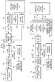
- FIGURE 1 shows
prior art receiver 10 havingantenna 12 which feeds intoantenna preamp assembly 101. This is followed by L1/L2 frequency selector 102 and L-band down-conversion 103 which converts either the L1 signal or the L2 signal to a second IF frequency. The local oscillators for the down-conversion are provided byreference oscillator 107 andfrequency synthesizer 108. The second IF (output from conversion 103) goes intoanalog circuit 104 for code and carrier wipe off. This is where the code transmitted by the satellite is compared and matched with the receiver's estimate of the code, and the carrier is compared with the receiver's estimate of the carrier. - Carrier frequency changes as a function of doppler velocity between the satellite and the user, and is the way the GPS measures relative velocity.
Code generation 109 andcarrier synthesizer 110 feed the code and carrier to the code/carrier wipe off circuitry and operate under control ofcomputer 11. - After code and carrier wipe off, the signal is digitized in analog to digital (A/D)
converter 105 and base band detected inmodule 106. The output of the base band predetection comprises the estimate of the error between the code and carrier that is transmitted from the satellite and the code and carrier prediction that is being made by the receiver. The error signal from the base band predetection tomicroprocessor 11 is used to generate new code and carrier states inmodules - For a more complete understanding of the typical receiver system reference is made to U.S.Patent 4,468,793 dated August 28, 1984, entitled "Global Position System (GPS) Multiplexed Receiver," which reference is hereby incorporated by reference herein.
- Turning now to FIGURE 2, there is shown
receiver 20 which utilizesantenna 22 feeding intoantenna preamp assembly 101 which in turn feeds into L1/L2 frequency selector 102, which in turn feeds into L-band downconversion 103, all operating under control ofreference oscillator 107 andfrequency synthesizer 108 in the same manner as similar numbered modules ofreceiver 10 of the prior art shown in FIGURE 1. - The output of L-band down
conversion 103 is provided to analog to digital (A/D)AGC circuit 201 which is different from the A/D circuit in FIGURE 1. A/D circuit 201 employs a null zone Automatic Gain Control (AGC) technique which provides added immunity against jamming. The A/D converter provides a four level output signal to signalprocessing circuits circuits - The outputs of
circuits signals 205 going toprocessor computer 21. They are similar to the outputs of FIGURE 1 going toprocessor 11 in that they represent the error between the receiver's estimate of code and carrier phase and the actual code and carrier phase being received.Signal 206 is the control fromprocessor 21 back tocircuits -
Modules circuit element 201 we have added null zone processing, which takes advantage of the spectral characteristics of the GPS signal and the spectral characteristics of the most common GPS jamming signals, which are CW signals. The null zone circuitry is desensitized to process CW energy, thereby yielding up to a 9dB improvement in jamming immunity against CW jammers. -
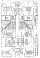
Circuit elements - FIGURE 3 shows a block diagram containing more detail of
system 20 showing one implementation of the receiver. Note thatmodules times 17circuit 103. The exact arrangement of this circuit is dependent upon the arrangement of the various components, and this could be one circuit or multiple pieces separated and is driven by specific application requirements. - It should be noted that
reference oscillator 107 operates at an off beat frequency of 20.4608 megahertz or 2 x 10.2304 megahertz. Conventional GPS reference frequency is 10.2300 megahertz. It is the frequency offset (in thiscase 400 HZ) that allows us to implement digital oscillators insidechannels -
Processor 21 is an implementation of the computer using the Intel chip set such thatelement 304 is anIntel 80386 andelement 305 is anIntel 80387 floating point unit. The computer also includes static RAM 306,EPROM 308 where the program code is stored, and interface andglue logic 307. Glue logic provided address decode functions, interrupt control functions, DMA functions, and miscellaneous housekeeping required for the computer.Element 31 provides the input output reference between the GPS core receiver and the rest of the world. -
Element 31 has an I/O function 309,bus drivers 310 for parallel I/O andserial drivers 311 for a serial I/O. - FIGURES 4-4C show aspects of the null zone A to D converter (201, FIGURE 3).
- FIGURE 4A shows the functional implementation of the null zone technique with 4 bit outputs A, B, C and D.
- FIGURE 4B is a truth table for the outputs of FIGURE 4A, and FIGURE 4C shows the difference in spectral content between a gaussian wave form and a sinusoidal wave form. The sinusoidal wave form is what you see when a CW jammer is incoming along with the GPS signal.
- The advanced A/D conversion process shown in FIGURE 4A is a modified version of a scheme called null-zone detection and was adapted for use for two reasons:
- . Reduction in the number of digital data bits being processed, which substantially decrease the size and power consumption of the processor, making it more reliable and much less expensive; and
- . Additional resistance against constant envelope or continuous wave (CW) interference. CW jamming can be particularly troublesome during signal acquisitions on the C/A-code.
- FIGURE 4A shows the different aspects of the A/D conversion process. Autommatic gain control (AGC)
circuit 401 maintains the raw incoming analog signal at a constant level. Three threshold detectors 403-405 quantize the incoming voltage into one of four values. When the incoming waveform's probability distribution function is gaussian in shape, as would be the case for broadband noise, the four values are assigned weights of -16, -4, +4, +16. This Weighting approximates a linear detector. The automatic gain control (AGC) maintains the percentage of ±16 values as a constant. - A
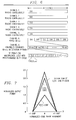
separate detector 406 determines if the signal is, indeed, gaussian or if it has a strong CW component. The probability distribution function of these two cases is very different. If a strong CW component exists, then a waveform with equivalent power will spend a larger percentage of time near the high and low thresholds. The CW detector senses this condition, and the weights applied to the four values change to -16, -1, +1, +16. The ±1 values deemphasize signal between the high and low thresholds where less GPS signal can be extracted. The waveform straddling the high and low thresholds is rich in GPS signal and maintains full weighting. - FIGURE 5 shows the performance gain using this detector approach. At a CW jammer-to-signal ratio (J/S) of 50 dB, the detector using 4/16 weighting preserves 7 dB of additional signal, compared to a linear detector and 9 dB using the 1/16 weighting. The receiver uses this increase in signal power to operate despite much more CW interference.
- FIGURE 6 shows one common version of the receiver timing which demonstrates the flexibility of six hardware channels by tracking combinations of L1 and L2 simultaneously. This mode will have five channels tracking L1 continuously and one channel roving on L2 across the five signals at least once every 30 seconds. By selecting the L1/L2 duty cycle in software, the receiver can easily be tailored for the unique conditions of future applications.
- FIGURE 7 shows the signal sensitivity gain by simultaneously tracking and vector summing the C/A and P(Y)-code signals from a single satellite.
- The C/A and P(Y)-code signals were combined inside the receiver to create 4.5 dB additional signal power when compared to P(Y)-code alone. The receiver can use this extra power against broadband jammers or beneath thick foliage. The satellite transmits the C/A-code with 3 dB more power than P(Y)-code to assist acquisition by receivers. But, before a conventional receiver can establish steady-state P(Y)-code track, it suspends tracking C/A-code. This receiver implementation removes that deficiency.
- FIGURE 7 illustrates the relative signal strengths of C/A, P(Y), and C/A plus P(Y)-code. Both C/A and P(Y)-code signals are demodulated separately using the extra correlators in the PCOAC. Then software adds the two signals together and forms a composite vector sum. Because there is no correlation between the broadband noise of the two signals, the composite signal is 4.5 dB stronger than the P(Y)-code signal.
- Returning briefly to FIGURE 3, the receiver employs a fast multiplexing or switching technique between the L1 and L2 signals as shown. Note that both L1 and L2 enter hybrid circuit 302, but only one signal comes out. That is because the channels are capable of quickly switching between L1 code state and carrier phase and L2 code state and carrier phase. This preserves a single signal path for L1 and L2 having the effect that there is no interchannel bias between L1 and L2 and no interchannel bias between any of the channels. This technique also allows us to build a full function receiver with only a single RF signal path and a single A/D converter, thus eliminating at least 50 percent of the expensive RF circuitiy required for a GPS receiver. The RF switch is a conventional switch, but this technique is made possible because
channels - FIGURE 8 is a block diagram of
dual channel decoder 202, which is detailed in the above-identified copending patent application entitied "Method and System for a Multi Channel and Search Global Position System Signal Processor." The details of operation of that system will not be repeated herein. - FIGURE 9 represents pictorially the problem inherent with determining position from a series of satellites. There are two main requirements to track a satellite's transmitted signal. One is to determine the code state (C/A-code or P(Y)-code) of the signal being received. The second is to determine the doppler effect (frequently offset) of the signal being received. The code changes are akin to two people talking next to each other. Whatever the speaker says, the hearer receives at the exact same time. However, in the speaker were to move away far enough, the speaker would output information, and that information would arrive at the receiving person sometime later. Thus, if the speaker were reciting the alphabet, A, B, C, D in order, the receiver might be listening to the letter ""A" while the sender is speaking the letter "C". This is called the code being received. By knowing the delay, i.e., the number of bits different in the transmitted information, one could figure out the distance, and thus the position of the receiver along a single straight line from the sender or satellite. This repetition from three other satellites yields precise position and time of the receiver.
- In addition, the relative velocity between the satellite and the receiver is translated into a doppler shift in frequency of the transmitted carrier signal. Therefore, initial acquisition of a GPS signal from a single satellite is akin to a two dimensional problem where one dimension is the code or position state and the other dimension is the doppler or velocity state. The problem can then be described graphically in three dimensions (FIGURE 9). Samples of the incoming signal are integrated in time across the eight correlators within each channel. The results of the sampling are stored at intervals of Ti/8 where Ti is the total integration time. This is shown in the code/time plane. Then, via an eight point discrete fourier transform and adjacent doppler bin interpolation, this is converted to 13 x 8 samples in the code/frequency domain. Thus in a single search time, the receiver can determine the existence or absence of signal in many more code and doppler states than are possible with a conventional receiver.
- FIGURE 9, for comparison, shows the
search area 901′ and 902′ covered per channel and per integration time by twoprior generation receivers - Returning briefly to FIGURE 8,
noise meter 819 is tied to the ninth correlator in each channel. It has a high sampling rate tied to the DFT samples for search. It is programmable for C/A and P(Y)-code bandwidths and is capable of aiding search by setting the thresholds in the search processor for the Tong detectors. This is done without aiding or intervention or time line requirements from the computer. - FIGURE 10A shows a typical noise meter, and FIGURE 10B shows the predetection integration sampling associated with
predetection integrator 1005 for the P(Y)-code and C/A code for three different frequency plans. The noise meter measures the variance of integration samples. The noise meter consists of three major components: - a
pre-detection integrator 1005 - a
power discriminator 1006 - a
post-detection integrator 1007. - The pre-detection integration period determines the bandwidth over which noise power is measured and is normally set to roughly match the bandwidth of the code being received. Taking absolute values provides a discriminant for the variance of I and Q. Post-detection integration acts as an averaging process to improve the quality of the noise power estimate. The noise meter can measure the power of gaussian, CW or plus noise.
- The pre-detection integration period determines the noise power bandwidth. For normal operation, the bandwidth is set to match the bandwidth of the desired code (i.e., 10 MHz for P(Y)-code and 1 MHz for C/A-code). Pre-detection integration band width is equal to:

- For tracking operations, the noise meter post-detection integration period is the same as the sample integration period. During search, the noise meter post-detection integration period is the same as the DFT period.
- Pre-detection integration samples are accumulated for the entire post-detection integration period.
- Variance of I and Q integration samples in a gaussian noise environment is calculated using the following equation:

- The expected value of noise meter data in a gaussian noise environment is calculated using the following equation:


- For measuring gaussian noise, modulating P(Y)-code onto the incoming signal prior to pre-detection integration has a negligible on noise meter data. However, if the noise has some CW content, modulating P(Y)-code onto the incoming signal prior to pre-detection integration reduces the effect CW noise has on final post-detection values. The noise meter is also capable of measuring CW and/or pulse noise.
- FIGURE 8 shows the search engine works with the noise meter, the DFT, and the I and Q samples. First, I and Q samples from the eight correlators are stored in I and Q
sample buffering memory 821. (I and Q means inphase and quadrature, which are the two phases which define a vector.) Once stored in memory, theDFT module 824 reads these samples out, applies the appropriate multiply vectors to each sample and adds the product to the accumulated value for each of the seven frequency bins. - After a DFT cycle is complete, the
search processor 823 will go and read the samples and apply a Tong detect algorithm to them to determine if signal is present at a particular code state and carrier frequency. -
DFT module 824 is shown in FIGURE 11 and uses an approximation of the standard eight-point DFT algorithm to process sample integration data into seven frequency bins based on a complex 2-bit vector set. As a pre-processor to search processor module 823 (FIGURE 8),DFT module 824 extends the frequency range of a search by up to a factor of seven, thus reducing search time in most applications. - The approximate DFT algorithm differs from the standard eight-point DFT algorithm only by the vector set that is used. The approximate vector set is used to reduce the circuitry required for implementation.
- FIGURE 12 shows the vector set, [V₀, V₁, V₂, V₃, V₄, V₅, V₆, and V₇], used for this approximate DFT algorithm.
- This algorithm can also expressed using the following matrix multiply equation:

where Zn represents the complex value In + jQn. Thus, a set of eight integration samples (Z₀, Z₁, Z₂, Z₃, Z₄, Z₅, Z₆ and Z₇) are multiplied by a vector sequence producing frequency data for a given frequency bin. - The output level associated with each doppler bin is affected by doppler attenuation. Attenuation increases as signal offset from the internal generated carrier center frequency increases. The result is a non-linear distribution over the full range of the eight-point DFT output. In addition to the seven frequency bins produced by the DFT module, the search processor module generates six frequency bins by interpolating between the seven bins generated by the DFT module. This provides a means of filling in the signal to noise ratio holes between frequency bins.
- Search processor 823 (FIGURE 8) controls the DFT circuitry. A discrete fourier transform is performed on the I and Q data sample integration set. Frequency data from the DFT consists of seven I and Q pairs (representing seven doppler bins). The search processor interpolates between adjacent pairs of doppler bin data to obtain six additional doppler bins for a total of thirteen doppler bins for each of the correlators. A Tong detection algorithm is performed on this data to determine if a signal is present. If not, the search processor moves code to a new code state and continues the search there. The search continues until one of three conditions exist: a signal is found, the maximum search length (specified by the host processor) is reached, or an error condition occurs. Except for setup, the search processor operates independent of the resident computer.
- The seven frequency bins from the DFT are labelled B₀, B₂, B₄, B₆, B₈, B₁₀ and B₁₂ from the most positive to the most negative doppler, respectively. The search processor interpolates between these frequency bins providing bins B₁, B₃, B₅, B₇, B₉, and B₁₁. These interpolated frequency bins indicate signal power found at a center frequency which is the arithmetic mean of the center frequencies of the even frequency bins from which it was interpolated.

- Interpolation by way of the above equation means that odd doppler bins (interpolated values) will on average have a magnitude 1.414 times that of the magnitude of the even doppler bins. For this reason the search threshold used for Tong detection interpolated bins is 1.414 times the threshold for non-interpolated bins.
-
Search processor 823 calculates envelopes for each complex (I+jQ) doppler bin value. Ideally, envelopes would be calculated as the square root of the sum of the squares; however, in order to significantly reduce circuit complexity a Robertson approximation is used as follows:
where [ ] indicates absolute value and E is the resultant envelope. - Several factors of the configuration contribute to final envelope magnitude and standard deviation and channel C/No loss.
- FIGURE 14 shows gain of each DFT bin relative to the magnitude of the sample integration data.
- FIGURE 15 shows C/No loss for each doppler bin as a function of doppler. The effect of doppler attenuation is factored into the values shown on this FIGURE. Doppler attenuation is loss which occurs because the final signal IF does not exactly match the carrier generator digital oscillator frequency.
- FIGURE 16 shows the effect each stage of signal correlation has on C/No and envelope magnitude and standard deviation. These factors are useful for determining C/No loss, determining if envelopes will overflow, and for setting search threshold (Vt1).
- For example, if carrier hard-limiting is off, adjacent correlator presuming is on, the integration clock period is 250 microseconds, and the frequency of the incoming signal is 1,000 Hz off the carrier generator. (See copending patent entitled "Method and System for a Dual channel and Search Global Position System Signal Processor"). C/No loss is calculated as follows:

The maximum envelope magnitude can be calculated as follows:
This is valuable in determining if envelope calculations will overflow for a given set of conditions.
Noise variance will have a gain of:
- Thus, for this set of conditions, 2.87 is the ratio of the standard deviation of noise of the envelope to the standard deviation of noise at the input of the PCOAC. This factor is useful for calculating search threshold, Vt1.
- The Vt1 and Vt2 thresholds are used in the Tong detection algorithm in determining whether or not signal is present as discussed previously. The host processor can either set Vt1 and Vt2 at a fixed value or specify Vt1 and Vt2 to be calculated by multiplying the output of the noise meter by a specified gain (Gt). The reason there are two voltage thresholds is because the magitudes of odd doppler bins are greater than the magnitudes of even doppler bins by a factor of the square root of two, also as discussed previously. Vt1 is used for even doppler bins and Vt2 (Vt1 multiplied by the square root of two) for odd doppler bins.
- During search, the noise meter's post-detection integrations are continued until all DFT input samples are collected. The total integration period affects the magnitude of the final noise measurement. These equations were shown previously.
- Vt1 is always calculated at the completion of each DFT by multiplying noise measurement by a gain value (G+) specified by the host processor or it is provided by the host processor directly.
- The search processor calculates Vt2 by multiplying Vt1 by the square root of two.
- A diagram of the Tong detection algorithm is shown in FIGURE 17. The Tong detection algorithm is designed to decide when signal is present. The Tong detector keeps a Tong count for each of the 104 (13
doppler bins times 8 correlators) search bins for which it is trying to determine if signal is present. Initially, the Tong count (K) is set to one 1712. Thesearch processor 1703 compares eachenvelope 1702 to its appropriate threshold (Vt1 or Vt2). If the envelope is greater than or equal to the threshold, the Tong count for that search bin is incremented 1704. If the envelope is less than the threshold, the Tong count is decremented 1705. When a Tong count for a search bin reaches zero 1707, the signal at that search bin is declared "not found" and that search bin is no longer active. (Tong detection is no longer performed on it). If all 104 Tong counts reach zero, the signal is declared "not found" for all search bins at the current code state. When this occurs, the code is retarded 1710 to a new code state. The Tong detector is reset 1712 (all Tong counts are set to 1) and search continues. Signal is declared "found" 1708 if a Tong count is incremented to the value "A" 1706 set by the host processor. - For some applications it may be desirable for the search processor to ignore the envelopes from certain correlators or for certain frequency bins. The search processor provides the host processor the means with which to mask the unwanted correlators or frequency bins.
- A search that is in progress can be temporarily suspended. This might be done in the event that the host processor has determined the input signal to be no good, such as when a pulse jammer is detected. Search suspend is tied to DFT cycles. Tong detection is not performed on DFT data which was taken during search suspend. Once suspend is de-asserted, Tong detection resumes on data from the next DFT cycle.
- Each channel has a (hardware) suspend search input. The host processor enables and disables the suspend input for a channel by setting a suspend input enable bit. In addition, the host processor can directly suspend search.
- The search processor implements a mush counter which counts the number of DFT periods the search processor has spent on a particular code state. The purpose of the mush counter is to prevent the search processor from getting hung up at a particular code state because of a bad threshold, a jamming signal or high side-lobe. If the mush counter determines that the number of DFT samples spent on a particular code state is equal to a maximum mush count specified by the host processor, then the mush counter function can either halt search or force the search processor to go on to the next code state, depending on a bit set by the host processor.
- The search processor also incorporates a hit counter which can be used by the host processor to aid in determining the adequacy of a threshold setting. It can also play a role in designs for non-gaussian environments. The hit counter only provides information to the host processor; it does not affect the operation of the search processor. The hit counter counts the number of hits for a specified number of DFT samples. It is incremented each time in active Tong count is incremented. Once the hit count is complete, it is transferred to a latch to be read by the host processor. The hit counter is cleared after the transfer to keep count of hits for the next set of DFT samples. A large hit count could be indicative of a low threshold.
- FIGURE 18 summarizes the performance of four different receiver architectures under various conditions of signal aiding and jamming levels. The metric used is time to first fix or the time from the point at which the receiver is turned-on until it is navigating to specified accuracy. In all cases the unique receiver architecture which is P(Y) described herein produces a system that gives the best performance independent of jamming level and independent of aiding quality.
- It should be noted that the GPS Satellite System has in it an algorithm which converts the P(Y)-code to Y-Code for special applications. This algorithm is not widely known. Therefore only those receivers that have a special access to the algorithm can utilize Y-code.
- In operation a special code called the CV code can be sent to the satellite, and the satellite using its special algorithm, will then convert the P(Y)-code signals to a Y-code signal. Receivers which have been outfitted with a special circuit which is available from the U.S. government, also in response to a corresponding CV code, will convert to a Y-code receiver. In this context CV code stands for cryptovariable. In prior receivers, there has been one AOC circuit for each channel. In the instant disclosure there is one AOC alternative circuit embedded in each dual channel chip. Therefore, the AOC alternative each services two channels. Accordingly, once the CV code has been received or inserted into the receiver, the receiver becomes a six channel Y-code receiver with only three AOC alternative circuits embedded therein. The AOC alternative, which is used in place of the standard AOC circuit available from the government, takes advantage of the fact that the circuitry is shared between two channels and that by being embedded in the same chip with the search processor it can support the high code chipping rates of 28 megahertz and also the stopping of the code associated with search code state advances and retards. We do this by multiplexing a portion of the circuit.
- Although this description describes the invention with reference to the above specified embodiments, the claims and not this description limit the scope of the invention. Various modifications of the disclosed embodiment, as well as alternative embodiments of the invention, will become apparent to persons skilled in the art upon reference to the above description. Therefore, the appended claims will cover such modifications that fall within the true scope of the invention.
Claims (27)
- A receiver for determining a global positioning parameter from analog signal information received from a plurality of navigational satellites, said signal information having data shifts dependent upon distance and frequency shifts dependent upon the relative velocity between the satellite's transmission position and the geographical position of said receiver, and wherein said analog signal is significantly weaker than ambient atmospheric noise, said receiver comprising: a digital signal processing circuit for acquiring valid signals in the presence of said noise, for estimating the correct position and for correcting said estimate based upon data exchanged between said acquisition circuit and said processor.
- A receiver for determining a global positioning parameter from analog signal information received from a plurality of navigational satellites, said signal information having data shifts dependent upon distance and frequency shifts dependent upon the relative velocity between the satellite's transmission position and the geographical position of said receiver, and wherein said analog signal is significantly weaker than ambient atmospheric noise, said receiver comprising:
a first stage for accepting said analog signals from a plurality of said satellites and for modulating said received analog signals into equivalent IF analog signals;
an analog to digital converter for converting said modulated IF signals into digital signals prior to further processing of said IF signals;
a computer, and
a digital signal processing circuit for acquiring valid signals in the presence of said noise, for estimating the correct position and for correcting said estimate based upon data exchanged between said tracking circuit and said computer. - The receiver set forth in claim 2 wherein said converter includes a full null zone detector.
- The receiver set forth in claim 2 wherein said digital signal processing circuit includes a noise meter for aiding in said signal acquisition or aiding in signal tracking.
- The receiver set forth in claim 2 wherein said analog satellite signal information is coded in P(Y)-code and in C/A code, and wherein said digital signal processing circuit includes:
circuitry operable to track both said information codes simultaneously on a single channels. - The receiver set forth in claim 2 wherein said receiver includes an offbeat oscillator frequency which allows for digital oscillator to resolve carrier and P(Y)-code clock phase in order to process said P(Y)-code.
- The receiver set forth in claim 5 wherein said digital signal processing circuit includes:
a plurality of signal correlators for aiding in said signal acquisition of P(Y)-code and C/A code. - The receiver set forth in claim 1 further comprising:
circuitry for tracking multiple channel is simultaneously, said circuitry including:
circuitry for assigning a different signal to a plurality of said channels; and
circuitry for time sharing a plurality of signals on the remainder of said channels. - The receiver set forth in claim 2 wherein said analog satellite signal information is coded in P(Y)-code and in C/A code and wherein said receiver further includes:
circuitry for receipt of satellite data indicating status of anti-spoofing ; and
circuitry operative in response to receipt of said status for converting said receiver from P-code operation to Y-code operation. - The receiver set forth in claim 9 wherein said last mentioned converting circuitry is shared between a plurality of channels.
- A method for determining a global positioning parameter from analog signal information received from a plurality of navigational satellites, said signal information having data shifts and frequency shifts dependent upon the distance and relative velocity between the satellite's transmission position and the geographical position of said receiver, and wherein said analog signal is significantly weaker than ambient atmospheric noise, said method comprising the steps of:
accepting said analog signals from a plurality of said satellites and modulating
said receiver analog signals into equivalent IF analog signals;
converting said analog IF signals to digital signals prior to further processing of said IF signals;
processing said digital signals for acquiring valid signals in the presence of said noise;
estimating the correct position; and
continually updating said estimate based upon data exchanged between said estimating function and said signal processing function. - The method set forth in claim 11 wherein converting includes the step of:
implementing full null zone detection. - The method set forth in claim 11 wherein said analog satellite information is coded in P(Y)-code and in C/A code, and wherein said signal processing function includes:
tracking both said information codes simultaneously on a single channel. - The method set forth in claim 11 wherein said estimating function includes:
vector summing said acquired P(Y) and C/A codes. - The method set forth in claim 11 wherein said signal processing function includes
the use of an offbeat oscillator frequency which allows for phase resolution of digital oscillators to process said P(Y)-code. - The method set forth in claim 11 further comprising the function of:
tracking multiple channels simultaneously, said tracking including:
assigning a different signal to each of several said channels; and time sharing a plurality of signals on said remainning channel. - A system for acquiring signals from at least one global positioning system satellite, said system comprising:
and analog receiver section for receiving said signals together with atmospheric noise and for developing an IF signal containing a spread spectrum of signals;
circuitry for converting said IF signal to a digital equivalent; and
circuitry for locking on to valid signals, said locking circuitry including:
a digital signal processor; and
a host computer for control and processing of data contained in said signal; said
data containing information for allowing estimates to be made with respect to the frequency and data shifts of said signal. - The system set forth in claim 17 further comprising:
circuitry for selectively adapting any channel on any of said signal processing circuits to process either or both P(Y) and C/A signals from said satellite. - The system set forth in claim 17 wherein each channel of said multi-channel signal processing circuit is operable for receiving both P(Y)-code and C/A code simultaneously, said system further including:
circuitry for vector summing said P(Y) and C/A code to aid in tracking said signal. - The method for acquiring signals from at least one satellite of a global positioning system, said method comprising the steps of:
receiving said signals in analog form together with atmospheric noise and for developing an IF signal containing a spread spectrum of signals;
converting said if signals to a digital equivalent; and
locking onto valid signals, said locking step including the reiterative step of:
estimating received signals with respect to frequency and code state of said signals with a processor, said estimates being compared with actual signals for allowing new estimates to be calculated so as to perform said locking. - The method set forth in claim 20 wherein said converting step includes the step of:
performing null zone detection. - The method set forth in claim 20 wherein said method includes the step of:
using an off beat oscillator frequency for resolving signal phase. - The method set forth in claim 20 wherein said locking step includes the use of a plurality of dual channel signal processing circuits each operable to perform said comparison.
- The method set forth in claim 20 further comprising the step of:
selectively adapting any channel on any of said processing circuits to receive P(Y) or C/A signals simultaneously from said satellite. - The method set forth in claim 20 wherein each channel said dual channel signal processing is operable for receiving both P(Y)-code and C/A code simultaneously, said method further including the step of:
vector summing of said P(Y) and C/A code to aid in tracking said signal. - A receiver as claimed in claim 1 or claim 2 and wherein said parameter is position, velocity or time.
- A method as claimed in claim 11 wherein said parameter is position, velocity or time.
Applications Claiming Priority (2)
| Application Number | Priority Date | Filing Date | Title |
|---|---|---|---|
| US07/662,585 US5347284A (en) | 1991-02-28 | 1991-02-28 | System and method for a digital navigation satellite receiver |
| US662585 | 1991-02-28 |
Publications (2)
| Publication Number | Publication Date |
|---|---|
| EP0501829A1 true EP0501829A1 (en) | 1992-09-02 |
| EP0501829B1 EP0501829B1 (en) | 1999-06-16 |
Family
ID=24658320
Family Applications (1)
| Application Number | Title | Priority Date | Filing Date |
|---|---|---|---|
| EP92301741A Expired - Lifetime EP0501829B1 (en) | 1991-02-28 | 1992-02-28 | System and method for a digital navigation satellite receiver |
Country Status (3)
| Country | Link |
|---|---|
| US (1) | US5347284A (en) |
| EP (1) | EP0501829B1 (en) |
| DE (1) | DE69229417T2 (en) |
Cited By (18)
| Publication number | Priority date | Publication date | Assignee | Title |
|---|---|---|---|---|
| WO1997040398A2 (en) * | 1996-04-25 | 1997-10-30 | Sirf Technology, Inc. | Spread spectrum receiver with multi-bit correlator |
| EP0806079A1 (en) * | 1994-09-09 | 1997-11-12 | Omnipoint Corporation | Transmission and reception of cpm spread-spectrum communications |
| WO1998019408A2 (en) * | 1996-10-30 | 1998-05-07 | Lsi Logic Corporation | Single-chip dbs receiver |
| WO1999010976A1 (en) * | 1997-08-27 | 1999-03-04 | Radioscape Limited | Communications apparatus |
| WO2000028677A1 (en) * | 1998-11-11 | 2000-05-18 | Samsung Electronics Company, Limited | Receiver for pseudo-noise signals from satellite radio-navigation systems |
| WO2000028346A1 (en) * | 1998-11-11 | 2000-05-18 | Samsung Electronics Company, Limited | Digital correlator for a receptor of signals from satellite radio-navigation systems |
| WO2001009634A2 (en) * | 1999-06-17 | 2001-02-08 | Samsung Electronics Company, Limited | Portable gps receiver for a personal safety system |
| US6393046B1 (en) | 1996-04-25 | 2002-05-21 | Sirf Technology, Inc. | Spread spectrum receiver with multi-bit correlator |
| US6421609B2 (en) | 1996-04-25 | 2002-07-16 | Sirf Technology, Inc. | GPS receiver with cross-track hold |
| US6466612B2 (en) | 1997-03-28 | 2002-10-15 | Sirf Technology, Inc. | Multipath processing for GPS receivers |
| EP1271102A2 (en) * | 1996-04-25 | 2003-01-02 | Sirf Technology, Inc. | Spread spectrum receiver with multi-bit correlator |
| EP1209483A3 (en) * | 1996-04-25 | 2003-03-05 | Sirf Technology, Inc. | Spread spectrum receiver with multi-bit correlator |
| EP1616391A2 (en) * | 2003-04-18 | 2006-01-18 | Motorola, Inc. | Method and device for detecting an interference condition |
| EP1674881A2 (en) * | 1997-11-19 | 2006-06-28 | IMEC vzw | Method and apparatus for receiving GPS/GLONASS signals |
| CN101910858A (en) * | 2007-11-15 | 2010-12-08 | 高通股份有限公司 | Gnss receiver and signal tracking circuit and system |
| RU2503970C2 (en) * | 2003-10-28 | 2014-01-10 | Тримбл Нэвигейшн Лимитед | Evaluation of ambiguity of gnss signals for three or more carriers |
| RU2616970C1 (en) * | 2016-01-27 | 2017-04-19 | Федеральное государственное казенное военное образовательное учреждение высшего образования "Военно-космическая академия имени А.Ф. Можайского" Министерства обороны Российской Федерации | Method of glonass system signal processing with frequency division |
| CN109547129A (en) * | 2018-11-27 | 2019-03-29 | 中国科学院光电研究院 | A kind of stepping Weighted T ong detection method |
Families Citing this family (104)
| Publication number | Priority date | Publication date | Assignee | Title |
|---|---|---|---|---|
| US5790587A (en) | 1991-05-13 | 1998-08-04 | Omnipoint Corporation | Multi-band, multi-mode spread-spectrum communication system |
| US5694414A (en) | 1991-05-13 | 1997-12-02 | Omnipoint Corporation | Multi-band, multi-mode spread-spectrum communication system |
| US5815525A (en) | 1991-05-13 | 1998-09-29 | Omnipoint Corporation | Multi-band, multi-mode spread-spectrum communication system |
| US5887020A (en) | 1991-05-13 | 1999-03-23 | Omnipoint Corporation | Multi-band, multi-mode spread-spectrum communication system |
| US5796772A (en) | 1991-05-13 | 1998-08-18 | Omnipoint Corporation | Multi-band, multi-mode spread-spectrum communication system |
| US5420516A (en) * | 1991-09-20 | 1995-05-30 | Audio Precision, Inc. | Method and apparatus for fast response and distortion measurement |
| US5917444A (en) * | 1995-05-22 | 1999-06-29 | Trimble Navigation Ltd. | Reduction of time to first fix in an SATPS receiver |
| USRE37408E1 (en) * | 1993-05-21 | 2001-10-16 | Trimble Navigation Ltd. | Reduction of time to first fix in an SATPS receiver |
| EP0634666A3 (en) * | 1993-06-28 | 1997-08-20 | Victor Company Of Japan | Receiving device for receiving and demodulating spectral diffusion-modulated GPS wave. |
| WO1995012945A1 (en) * | 1993-11-01 | 1995-05-11 | Omnipoint Corporation | Despreading/demodulating direct sequence spread spectrum signals |
| JPH07235913A (en) * | 1994-02-23 | 1995-09-05 | Sony Corp | Spread spectrum communication equipment and signal intensity detecting device |
| US5576715A (en) * | 1994-03-07 | 1996-11-19 | Leica, Inc. | Method and apparatus for digital processing in a global positioning system receiver |
| US5856998A (en) | 1994-09-09 | 1999-01-05 | Omnipoint Corporation | Method and apparatus for correlating a continuous phase modulated spread spectrum signal |
| US5627856A (en) | 1994-09-09 | 1997-05-06 | Omnipoint Corporation | Method and apparatus for receiving and despreading a continuous phase-modulated spread spectrum signal using self-synchronizing correlators |
| US5953370A (en) | 1994-09-09 | 1999-09-14 | Omnipoint Corporation | Apparatus for receiving and correlating a spread spectrum signal |
| US5629956A (en) | 1994-09-09 | 1997-05-13 | Omnipoint Corporation | Method and apparatus for reception and noncoherent serial correlation of a continuous phase modulated signal |
| US5881100A (en) | 1994-09-09 | 1999-03-09 | Omnipoint Corporation | Method and apparatus for coherent correlation of a spread spectrum signal |
| US5648982A (en) | 1994-09-09 | 1997-07-15 | Omnipoint Corporation | Spread spectrum transmitter |
| US5680414A (en) | 1994-09-09 | 1997-10-21 | Omnipoint Corporation | Synchronization apparatus and method for spread spectrum receiver |
| US5610940A (en) | 1994-09-09 | 1997-03-11 | Omnipoint Corporation | Method and apparatus for noncoherent reception and correlation of a continous phase modulated signal |
| US5757847A (en) | 1994-09-09 | 1998-05-26 | Omnipoint Corporation | Method and apparatus for decoding a phase encoded signal |
| US5832028A (en) | 1994-09-09 | 1998-11-03 | Omnipoint Corporation | Method and apparatus for coherent serial correlation of a spread spectrum signal |
| US5692007A (en) | 1994-09-09 | 1997-11-25 | Omnipoint Corporation | Method and apparatus for differential phase encoding and decoding in spread-spectrum communication systems with continuous-phase modulation |
| US5963586A (en) | 1994-09-09 | 1999-10-05 | Omnipoint Corporation | Method and apparatus for parallel noncoherent correlation of a spread spectrum signal |
| US5659574A (en) | 1994-09-09 | 1997-08-19 | Omnipoint Corporation | Multi-bit correlation of continuous phase modulated signals |
| US5754585A (en) | 1994-09-09 | 1998-05-19 | Omnipoint Corporation | Method and apparatus for serial noncoherent correlation of a spread spectrum signal |
| US5754584A (en) | 1994-09-09 | 1998-05-19 | Omnipoint Corporation | Non-coherent spread-spectrum continuous-phase modulation communication system |
| US5854813A (en) * | 1994-12-29 | 1998-12-29 | Motorola, Inc. | Multiple access up converter/modulator and method |
| US5602874A (en) * | 1994-12-29 | 1997-02-11 | Motorola, Inc. | Method and apparatus for reducing quantization noise |
| US5579341A (en) * | 1994-12-29 | 1996-11-26 | Motorola, Inc. | Multi-channel digital transceiver and method |
| CA2181807C (en) * | 1994-12-29 | 1999-09-28 | Robert C. Elder | Wideband frequency signal digitizer and method |
| US5748683A (en) * | 1994-12-29 | 1998-05-05 | Motorola, Inc. | Multi-channel transceiver having an adaptive antenna array and method |
| US5668836A (en) * | 1994-12-29 | 1997-09-16 | Motorola, Inc. | Split frequency band signal digitizer and method |
| US5754597A (en) * | 1994-12-29 | 1998-05-19 | Motorola, Inc. | Method and apparatus for routing a digitized RF signal to a plurality of paths |
| US5784403A (en) * | 1995-02-03 | 1998-07-21 | Omnipoint Corporation | Spread spectrum correlation using saw device |
| US5832022A (en) * | 1995-06-02 | 1998-11-03 | Omnipoint Corporation | Method and apparatus for controlling the modulation index of continuous phase modulated (CPM) signals |
| US6356607B1 (en) | 1995-06-05 | 2002-03-12 | Omnipoint Corporation | Preamble code structure and detection method and apparatus |
| US5745484A (en) * | 1995-06-05 | 1998-04-28 | Omnipoint Corporation | Efficient communication system using time division multiplexing and timing adjustment control |
| US5678169A (en) * | 1995-06-30 | 1997-10-14 | Trimble Navigation Limited | Receivers for down-conversion of L1 and L2 carrier frequency transmissions from orbiting global positioning system (GPS) satellites |
| US5710763A (en) * | 1995-07-31 | 1998-01-20 | Motorola, Inc. | Filtered fast Fourier transmultiplexer and method |
| US7092369B2 (en) | 1995-11-17 | 2006-08-15 | Symbol Technologies, Inc. | Communications network with wireless gateways for mobile terminal access |
| US5897605A (en) * | 1996-03-15 | 1999-04-27 | Sirf Technology, Inc. | Spread spectrum receiver with fast signal reacquisition |
| US6041280A (en) * | 1996-03-15 | 2000-03-21 | Sirf Technology, Inc. | GPS car navigation system |
| US6917644B2 (en) * | 1996-04-25 | 2005-07-12 | Sirf Technology, Inc. | Spread spectrum receiver with multi-path correction |
| US6018704A (en) * | 1996-04-25 | 2000-01-25 | Sirf Tech Inc | GPS receiver |
| US6047017A (en) * | 1996-04-25 | 2000-04-04 | Cahn; Charles R. | Spread spectrum receiver with multi-path cancellation |
| US6198765B1 (en) | 1996-04-25 | 2001-03-06 | Sirf Technologies, Inc. | Spread spectrum receiver with multi-path correction |
| US6141373A (en) * | 1996-11-15 | 2000-10-31 | Omnipoint Corporation | Preamble code structure and detection method and apparatus |
| US5898728A (en) * | 1996-11-22 | 1999-04-27 | Trw Inc. | Distributed analog-digital frequency dehopping system |
| US6282228B1 (en) | 1997-03-20 | 2001-08-28 | Xircom, Inc. | Spread spectrum codes for use in communication |
| US5983160A (en) * | 1997-04-21 | 1999-11-09 | Raytheon Company | Increase jamming immunity by optimizing processing gain for GPS/INS systems |
| US6776792B1 (en) | 1997-04-24 | 2004-08-17 | Advanced Cardiovascular Systems Inc. | Coated endovascular stent |
| US6005889A (en) * | 1997-07-17 | 1999-12-21 | Nokia | Pseudo-random noise detector for signals having a carrier frequency offset |
| US6366599B1 (en) | 1998-03-16 | 2002-04-02 | Trimble Navigation Limited | Fast acquisition of spread-spectrum signals by dynamically varying spacing of search bins |
| US6195328B1 (en) | 1998-04-15 | 2001-02-27 | The United States Of America As Represented By The Secretary Of The Air Force | Block adjustment of synchronizing signal for phase-coded signal tracking |
| US6175327B1 (en) | 1999-01-16 | 2001-01-16 | Sensors Systems, Inc. | GPS receivers with adaptive antenna systems for suppressing interference signals |
| US6137433A (en) * | 1999-03-18 | 2000-10-24 | The United States Of America As Represented By The Secretary Of Commerce | Scatterometer with adaptable spatial resolution |
| US6683923B1 (en) | 1999-04-16 | 2004-01-27 | Bd Systems, Inc. | Method and apparatus for detecting and tracking coded signals in a noisy background environment |
| US6411892B1 (en) | 2000-07-13 | 2002-06-25 | Global Locate, Inc. | Method and apparatus for locating mobile receivers using a wide area reference network for propagating ephemeris |
| US6166690A (en) * | 1999-07-02 | 2000-12-26 | Sensor Systems, Inc. | Adaptive nulling methods for GPS reception in multiple-interference environments |
| GB9929329D0 (en) * | 1999-12-10 | 2000-02-02 | Nokia Mobile Phones Ltd | Data processing |
| US6282231B1 (en) | 1999-12-14 | 2001-08-28 | Sirf Technology, Inc. | Strong signal cancellation to enhance processing of weak spread spectrum signal |
| US7970411B2 (en) | 2000-05-18 | 2011-06-28 | Sirf Technology, Inc. | Aided location communication system |
| US8078189B2 (en) | 2000-08-14 | 2011-12-13 | Sirf Technology, Inc. | System and method for providing location based services over a network |
| US7970412B2 (en) | 2000-05-18 | 2011-06-28 | Sirf Technology, Inc. | Aided location communication system |
| US6462708B1 (en) | 2001-04-05 | 2002-10-08 | Sirf Technology, Inc. | GPS-based positioning system for mobile GPS terminals |
| US7929928B2 (en) | 2000-05-18 | 2011-04-19 | Sirf Technology Inc. | Frequency phase correction system |
| US6427120B1 (en) * | 2000-08-14 | 2002-07-30 | Sirf Technology, Inc. | Information transfer in a multi-mode global positioning system used with wireless networks |
| US6389291B1 (en) * | 2000-08-14 | 2002-05-14 | Sirf Technology | Multi-mode global positioning system for use with wireless networks |
| US7949362B2 (en) | 2000-05-18 | 2011-05-24 | Sirf Technology, Inc. | Satellite positioning aided communication system selection |
| AU2001270043A1 (en) * | 2000-06-27 | 2002-01-08 | Sirf Technology, Inc. | Combined parallel and sequential detection for gps signal acquisition |
| US6856794B1 (en) * | 2000-07-27 | 2005-02-15 | Sirf Technology, Inc. | Monolithic GPS RF front end integrated circuit |
| US7616705B1 (en) | 2000-07-27 | 2009-11-10 | Sirf Technology Holdings, Inc. | Monolithic GPS RF front end integrated circuit |
| US7236883B2 (en) | 2000-08-14 | 2007-06-26 | Sirf Technology, Inc. | Aiding in a satellite positioning system |
| JP4896353B2 (en) * | 2000-08-24 | 2012-03-14 | サーフ テクノロジー インコーポレイテッド | Apparatus and method for reducing autocorrelation or cross-correlation in weak CDMA signals |
| US7680178B2 (en) | 2000-08-24 | 2010-03-16 | Sirf Technology, Inc. | Cross-correlation detection and elimination in a receiver |
| US6931233B1 (en) | 2000-08-31 | 2005-08-16 | Sirf Technology, Inc. | GPS RF front end IC with programmable frequency synthesizer for use in wireless phones |
| US7668554B2 (en) | 2001-05-21 | 2010-02-23 | Sirf Technology, Inc. | Network system for aided GPS broadcast positioning |
| WO2008024123A2 (en) | 2005-10-28 | 2008-02-28 | Sirf Technology, Inc. | Global positioning system receiver timeline management |
| US8138972B2 (en) * | 2003-09-02 | 2012-03-20 | Csr Technology Inc. | Signal processing system for satellite positioning signals |
| EP1680686A1 (en) | 2003-09-02 | 2006-07-19 | Sirf Technology, Inc. | Signal processing system for satellite positioning signals |
| US7365680B2 (en) | 2004-02-10 | 2008-04-29 | Sirf Technology, Inc. | Location services system that reduces auto-correlation or cross-correlation in weak signals |
| US7333053B2 (en) * | 2004-04-29 | 2008-02-19 | Novariant Inc. | Signal path system and method for a ranging signal receiver |
| US7472152B1 (en) | 2004-08-02 | 2008-12-30 | The United States Of America As Represented By The Secretary Of The Air Force | Accommodating fourier transformation attenuation between transform term frequencies |
| US7551127B2 (en) * | 2005-02-10 | 2009-06-23 | Motorola, Inc. | Reconfigurable downconverter for a multi-band positioning receiver |
| US7250899B2 (en) * | 2005-07-05 | 2007-07-31 | Sige Semiconductor (Europe) Limited | GPS receiver with improved immunity to collocated transmissions and method therefor |
| US7630430B2 (en) | 2005-07-25 | 2009-12-08 | Mstar Semiconductor, Inc. | Method and apparatus for accelerating correlation processing of GPS signal |
| US7729457B2 (en) * | 2005-07-25 | 2010-06-01 | Mstar Semiconductor, Inc. | Method of weak signal acquisition and associated apparatus |
| TWI301546B (en) | 2006-06-16 | 2008-10-01 | Via Tech Inc | Global position system signal receiver and searching and acquiring method thereof |
| US8442020B1 (en) * | 2006-09-12 | 2013-05-14 | Rockwell Collins, Inc. | Phase compensation system and method to correct M-code dual sideband distortion |
| US7990315B2 (en) * | 2006-09-15 | 2011-08-02 | Mediatek Inc. | Shared memory device applied to functional stages configured in a receiver system for processing signals from different transmitter systems and method thereof |
| US8515494B2 (en) * | 2007-01-13 | 2013-08-20 | Panasonic Automotive Systems Company Of America, Division Of Panasonic Corporation Of North America | Highly configurable radio frequency (RF) module |
| US8249616B2 (en) * | 2007-08-23 | 2012-08-21 | Texas Instruments Incorporated | Satellite (GPS) assisted clock apparatus, circuits, systems and processes for cellular terminals on asynchronous networks |
| US7800536B2 (en) * | 2007-10-11 | 2010-09-21 | Mediatek, Inc. | Signal acquisition/tracking method and correlator for the same |
| EP2204914B1 (en) * | 2008-12-30 | 2012-08-29 | u-blox AG | A method of processing a digital signal derived from a direct-sequence spread spectrum signal |
| DE102010004617A1 (en) * | 2010-01-13 | 2011-07-14 | Astrium GmbH, 82024 | Improvement of integrity communication in a satellite navigation system |
| US8798566B2 (en) * | 2011-03-30 | 2014-08-05 | Texas Instruments Incorporated | Rapid autonomous scan in FM or other receivers with parallel search strategy, and circuits, processes and systems |
| WO2013028443A1 (en) * | 2011-08-25 | 2013-02-28 | Bae Systems Information And Electronic Systems Integration Inc. | Single receiver gps pointing vector sensing |
| KR101564828B1 (en) * | 2014-01-20 | 2015-10-30 | 한국과학기술원 | Signal processing method for ultra-fast acquisition and tracking of severely attenuated spread spectrum signals with doppler frequency and apparatus thereof |
| CN105577230B (en) * | 2015-12-22 | 2018-01-16 | 北京理工大学 | The improved Tong detections decision method of convergent function |
| US10469126B1 (en) * | 2018-09-24 | 2019-11-05 | Huawei Technologies Co., Ltd. | Code synchronization for analog spread spectrum systems |
| CN112363188B (en) * | 2020-10-13 | 2021-06-11 | 无锡卡尔曼导航技术有限公司 | Tracking loop method and device for multi-diversity satellite navigation receiver |
| CN115499036B (en) * | 2022-11-14 | 2023-02-24 | 北京航空航天大学合肥创新研究院(北京航空航天大学合肥研究生院) | Parallel capturing method and storage medium for broadband spread spectrum signal |
| CN117310763B (en) * | 2023-11-30 | 2024-02-23 | 中国人民解放军国防科技大学 | Method and device for synchronizing pseudo code phase modulation-linear frequency modulation time division low-rail navigation signals |
Citations (2)
| Publication number | Priority date | Publication date | Assignee | Title |
|---|---|---|---|---|
| US4468793A (en) * | 1980-12-01 | 1984-08-28 | Texas Instruments Incorporated | Global position system (GPS) multiplexed receiver |
| GB2155268A (en) * | 1984-03-01 | 1985-09-18 | Standard Telephones Cables Ltd | Digital navstar receiver |
Family Cites Families (7)
| Publication number | Priority date | Publication date | Assignee | Title |
|---|---|---|---|---|
| US3609682A (en) * | 1969-07-16 | 1971-09-28 | Gen Electric | Augmented digital-error-correcting decoder |
| US4578678A (en) * | 1983-11-14 | 1986-03-25 | The United States Of America As Represented By The United States National Aeronautics And Space Administration | High dynamic global positioning system receiver |
| US4701934A (en) * | 1985-09-03 | 1987-10-20 | Motorola, Inc. | Method of doppler searching in a digital GPS receiver |
| US4821294A (en) * | 1987-07-08 | 1989-04-11 | California Institute Of Technology | Digital signal processor and processing method for GPS receivers |
| US5223843A (en) * | 1988-01-05 | 1993-06-29 | Rockwell International Corporation | High performance global positioning system receiver means and method |
| US4998071A (en) * | 1988-10-25 | 1991-03-05 | Cascade Microtech, Inc. | Noise parameter test method and apparatus |
| US5101416A (en) * | 1990-11-28 | 1992-03-31 | Novatel Comunications Ltd. | Multi-channel digital receiver for global positioning system |
-
1991
- 1991-02-28 US US07/662,585 patent/US5347284A/en not_active Expired - Lifetime
-
1992
- 1992-02-28 DE DE69229417T patent/DE69229417T2/en not_active Expired - Fee Related
- 1992-02-28 EP EP92301741A patent/EP0501829B1/en not_active Expired - Lifetime
Patent Citations (2)
| Publication number | Priority date | Publication date | Assignee | Title |
|---|---|---|---|---|
| US4468793A (en) * | 1980-12-01 | 1984-08-28 | Texas Instruments Incorporated | Global position system (GPS) multiplexed receiver |
| GB2155268A (en) * | 1984-03-01 | 1985-09-18 | Standard Telephones Cables Ltd | Digital navstar receiver |
Cited By (38)
| Publication number | Priority date | Publication date | Assignee | Title |
|---|---|---|---|---|
| EP0806079A4 (en) * | 1994-09-09 | 1999-10-13 | Omnipoint Corp | Transmission and reception of cpm spread-spectrum communications |
| EP0806079A1 (en) * | 1994-09-09 | 1997-11-12 | Omnipoint Corporation | Transmission and reception of cpm spread-spectrum communications |
| US6393046B1 (en) | 1996-04-25 | 2002-05-21 | Sirf Technology, Inc. | Spread spectrum receiver with multi-bit correlator |
| EP1271102A2 (en) * | 1996-04-25 | 2003-01-02 | Sirf Technology, Inc. | Spread spectrum receiver with multi-bit correlator |
| EP1209483A3 (en) * | 1996-04-25 | 2003-03-05 | Sirf Technology, Inc. | Spread spectrum receiver with multi-bit correlator |
| US6633814B2 (en) | 1996-04-25 | 2003-10-14 | Sirf Technology, Inc. | GPS system for navigating a vehicle |
| US6724811B2 (en) | 1996-04-25 | 2004-04-20 | Sirf Technology, Inc. | Pseudo-noise correlator for GPS spread-spectrum receiver |
| WO1997040398A3 (en) * | 1996-04-25 | 1998-02-26 | Sirf Tech Inc | Spread spectrum receiver with multi-bit correlator |
| US7729413B2 (en) | 1996-04-25 | 2010-06-01 | Sirf Technology, Inc. | Spread spectrum receiver with multi-bit correlator |
| WO1997040398A2 (en) * | 1996-04-25 | 1997-10-30 | Sirf Technology, Inc. | Spread spectrum receiver with multi-bit correlator |
| EP1271102A3 (en) * | 1996-04-25 | 2003-06-18 | Sirf Technology, Inc. | Spread spectrum receiver with multi-bit correlator |
| AU729697B2 (en) * | 1996-04-25 | 2001-02-08 | Sirf Technology, Inc. | Spread spectrum receiver with multi-bit correlator |
| US6748015B2 (en) | 1996-04-25 | 2004-06-08 | Sirf Technology, Inc. | Spread spectrum receiver with multi-bit correlator |
| US6400753B1 (en) | 1996-04-25 | 2002-06-04 | Sirf Technology, Inc. | Pseudo-noise correlator for a GPS spread spectrum receiver |
| US6421609B2 (en) | 1996-04-25 | 2002-07-16 | Sirf Technology, Inc. | GPS receiver with cross-track hold |
| WO1998019408A2 (en) * | 1996-10-30 | 1998-05-07 | Lsi Logic Corporation | Single-chip dbs receiver |
| US5953636A (en) * | 1996-10-30 | 1999-09-14 | Lsi Logic Corporation | Single-chip DBS receiver |
| WO1998019408A3 (en) * | 1996-10-30 | 1998-09-17 | Lsi Logic Corp | Single-chip dbs receiver |
| US6760364B2 (en) | 1997-03-28 | 2004-07-06 | Sirf Technology, Inc. | Multipath processing for GPS receivers |
| US6466612B2 (en) | 1997-03-28 | 2002-10-15 | Sirf Technology, Inc. | Multipath processing for GPS receivers |
| WO1999010976A1 (en) * | 1997-08-27 | 1999-03-04 | Radioscape Limited | Communications apparatus |
| EP1674881A2 (en) * | 1997-11-19 | 2006-06-28 | IMEC vzw | Method and apparatus for receiving GPS/GLONASS signals |
| EP1674881A3 (en) * | 1997-11-19 | 2008-04-16 | IMEC vzw | Method and apparatus for receiving GPS/GLONASS signals |
| US6441780B1 (en) | 1998-11-11 | 2002-08-27 | Samsung Electronics Co., Ltd. | Receiver for pseudo-noise signals from a satellite radio-navigation systems |
| US6441781B1 (en) | 1998-11-11 | 2002-08-27 | Samsung Electronics Co., Ltd. | Digital correlator for a receptor of signals from satellite radio-navigation systems |
| WO2000028346A1 (en) * | 1998-11-11 | 2000-05-18 | Samsung Electronics Company, Limited | Digital correlator for a receptor of signals from satellite radio-navigation systems |
| WO2000028677A1 (en) * | 1998-11-11 | 2000-05-18 | Samsung Electronics Company, Limited | Receiver for pseudo-noise signals from satellite radio-navigation systems |
| WO2001009634A2 (en) * | 1999-06-17 | 2001-02-08 | Samsung Electronics Company, Limited | Portable gps receiver for a personal safety system |
| WO2001009634A3 (en) * | 1999-06-17 | 2003-05-08 | Samsung Electronics Co Ltd | Portable gps receiver for a personal safety system |
| EP1616391A2 (en) * | 2003-04-18 | 2006-01-18 | Motorola, Inc. | Method and device for detecting an interference condition |
| EP1616391A4 (en) * | 2003-04-18 | 2007-06-20 | Motorola Inc | Method and device for detecting an interference condition |
| RU2503970C2 (en) * | 2003-10-28 | 2014-01-10 | Тримбл Нэвигейшн Лимитед | Evaluation of ambiguity of gnss signals for three or more carriers |
| CN101910858A (en) * | 2007-11-15 | 2010-12-08 | 高通股份有限公司 | Gnss receiver and signal tracking circuit and system |
| US8390513B2 (en) | 2007-11-15 | 2013-03-05 | Qualcomm Incorporated | GNSS receiver and signal tracking circuit and system |
| CN101910858B (en) * | 2007-11-15 | 2014-02-12 | 高通股份有限公司 | Gnss receiver and signal tracking circuit and system |
| RU2616970C1 (en) * | 2016-01-27 | 2017-04-19 | Федеральное государственное казенное военное образовательное учреждение высшего образования "Военно-космическая академия имени А.Ф. Можайского" Министерства обороны Российской Федерации | Method of glonass system signal processing with frequency division |
| CN109547129A (en) * | 2018-11-27 | 2019-03-29 | 中国科学院光电研究院 | A kind of stepping Weighted T ong detection method |
| CN109547129B (en) * | 2018-11-27 | 2021-09-24 | 中国科学院光电研究院 | Stepping weighting Tong detection method |
Also Published As
| Publication number | Publication date |
|---|---|
| DE69229417T2 (en) | 1999-12-30 |
| US5347284A (en) | 1994-09-13 |
| DE69229417D1 (en) | 1999-07-22 |
| EP0501829B1 (en) | 1999-06-16 |
Similar Documents
| Publication | Publication Date | Title |
|---|---|---|
| EP0501829A1 (en) | System and method for a digital navigation satellite receiver | |
| US7577524B2 (en) | Method and system for data detection in a global positioning system satellite receiver | |
| US5410750A (en) | Interference suppressor for a radio receiver | |
| US6922546B1 (en) | GPS signal acquisition based on frequency-domain and time-domain processing | |
| US5117232A (en) | Global system positioning receiver | |
| US5245628A (en) | Enhanced l1/l2 code channel for global positioning system receivers | |
| US6259401B1 (en) | Global positioning system receiver with improved multipath signal rejection | |
| US20050285781A1 (en) | GPS receiver and method for detecting a jammer signal using fast fourier transform | |
| US6959057B1 (en) | Method of enhancing signal tracking in global positioning system receivers | |
| FI110290B (en) | A method for determining the phase of information and an electronic device | |
| EP1538455A1 (en) | A method of calibrating an adaptive antenna array of a satellite navigation system | |
| AU4405999A (en) | Method and apparatus for signal processing in a satellite positioning system | |
| WO2001079877A2 (en) | Signal detector and method employing a coherent accumulation system to correlate non-uniform and disjoint sample segments | |
| WO1997044682A1 (en) | Variable suppression of multipath signal effects | |
| CA2317143A1 (en) | A satellite-based location system employing dynamic integration techniques | |
| US6643320B1 (en) | Receiver for DS-CDMA signals | |
| US6252546B1 (en) | Method and apparatus for processing multipath reflection effects in timing systems | |
| FI109311B (en) | Bit boundary detection method for global positioning system, involves utilizing index of largest element of determination vector formed based on received signal, to indicate bit boundary | |
| JP2004340855A (en) | Method and system of satellite positioning | |
| JP2839211B2 (en) | Wide-area positioning system receiver | |
| US20090168851A1 (en) | A correlator sum method for spread spectrum signal receivers | |
| EP1336860B1 (en) | High sensitivity GPS receiver | |
| US20110050496A1 (en) | Energy Domain Based Peak Reconstruction Methods And Apparatuses | |
| US7403558B2 (en) | Integrated circuit for code acquisition | |
| JP3787592B2 (en) | Satellite positioning method and satellite positioning system |
Legal Events
| Date | Code | Title | Description |
|---|---|---|---|
| PUAI | Public reference made under article 153(3) epc to a published international application that has entered the european phase |
Free format text: ORIGINAL CODE: 0009012 |
|
| AK | Designated contracting states |
Kind code of ref document: A1 Designated state(s): DE FR GB IT NL |
|
| 17P | Request for examination filed |
Effective date: 19921102 |
|
| 17Q | First examination report despatched |
Effective date: 19940406 |
|
| GRAG | Despatch of communication of intention to grant |
Free format text: ORIGINAL CODE: EPIDOS AGRA |
|
| GRAG | Despatch of communication of intention to grant |
Free format text: ORIGINAL CODE: EPIDOS AGRA |
|
| GRAH | Despatch of communication of intention to grant a patent |
Free format text: ORIGINAL CODE: EPIDOS IGRA |
|
| GRAH | Despatch of communication of intention to grant a patent |
Free format text: ORIGINAL CODE: EPIDOS IGRA |
|
| GRAA | (expected) grant |
Free format text: ORIGINAL CODE: 0009210 |
|
| AK | Designated contracting states |
Kind code of ref document: B1 Designated state(s): DE FR GB IT NL |
|
| PG25 | Lapsed in a contracting state [announced via postgrant information from national office to epo] |
Ref country code: IT Free format text: LAPSE BECAUSE OF FAILURE TO SUBMIT A TRANSLATION OF THE DESCRIPTION OR TO PAY THE FEE WITHIN THE PRE;WARNING: LAPSES OF ITALIAN PATENTS WITH EFFECTIVE DATE BEFORE 2007 MAY HAVE OCCURRED AT ANY TIME BEFORE 2007. THE CORRECT EFFECTIVE DATE MAY BE DIFFERENT FROM THE ONE RECORDED.SCRIBED TIME-LIMIT Effective date: 19990616 |
|
| REF | Corresponds to: |
Ref document number: 69229417 Country of ref document: DE Date of ref document: 19990722 |
|
| ET | Fr: translation filed | ||
| PLBE | No opposition filed within time limit |
Free format text: ORIGINAL CODE: 0009261 |
|
| STAA | Information on the status of an ep patent application or granted ep patent |
Free format text: STATUS: NO OPPOSITION FILED WITHIN TIME LIMIT |
|
| 26N | No opposition filed | ||
| REG | Reference to a national code |
Ref country code: GB Ref legal event code: IF02 |
|
| PGFP | Annual fee paid to national office [announced via postgrant information from national office to epo] |
Ref country code: NL Payment date: 20090210 Year of fee payment: 18 Ref country code: DE Payment date: 20090227 Year of fee payment: 18 |
|
| PGFP | Annual fee paid to national office [announced via postgrant information from national office to epo] |
Ref country code: GB Payment date: 20090106 Year of fee payment: 18 |
|
| REG | Reference to a national code |
Ref country code: NL Ref legal event code: V1 Effective date: 20100901 |
|
| GBPC | Gb: european patent ceased through non-payment of renewal fee |
Effective date: 20100228 |
|
| REG | Reference to a national code |
Ref country code: FR Ref legal event code: ST Effective date: 20101029 |
|
| PG25 | Lapsed in a contracting state [announced via postgrant information from national office to epo] |
Ref country code: FR Free format text: LAPSE BECAUSE OF NON-PAYMENT OF DUE FEES Effective date: 20100301 Ref country code: NL Free format text: LAPSE BECAUSE OF NON-PAYMENT OF DUE FEES Effective date: 20100901 |
|
| PG25 | Lapsed in a contracting state [announced via postgrant information from national office to epo] |
Ref country code: DE Free format text: LAPSE BECAUSE OF NON-PAYMENT OF DUE FEES Effective date: 20100901 |
|
| PG25 | Lapsed in a contracting state [announced via postgrant information from national office to epo] |
Ref country code: GB Free format text: LAPSE BECAUSE OF NON-PAYMENT OF DUE FEES Effective date: 20100228 |
|
| PGFP | Annual fee paid to national office [announced via postgrant information from national office to epo] |
Ref country code: FR Payment date: 20090206 Year of fee payment: 18 |