EP0502095B1 - Method and apparatus for controlling a fluid compression system - Google Patents
Method and apparatus for controlling a fluid compression system Download PDFInfo
- Publication number
- EP0502095B1 EP0502095B1 EP91900464A EP91900464A EP0502095B1 EP 0502095 B1 EP0502095 B1 EP 0502095B1 EP 91900464 A EP91900464 A EP 91900464A EP 91900464 A EP91900464 A EP 91900464A EP 0502095 B1 EP0502095 B1 EP 0502095B1
- Authority
- EP
- European Patent Office
- Prior art keywords
- compressor
- controller
- pressure
- computer
- compression means
- Prior art date
- Legal status (The legal status is an assumption and is not a legal conclusion. Google has not performed a legal analysis and makes no representation as to the accuracy of the status listed.)
- Expired - Lifetime
Links
- 239000012530 fluid Substances 0.000 title claims abstract description 12
- 230000006835 compression Effects 0.000 title claims description 24
- 238000007906 compression Methods 0.000 title claims description 24
- 238000000034 method Methods 0.000 title 1
- 238000012163 sequencing technique Methods 0.000 claims abstract description 3
- 230000005540 biological transmission Effects 0.000 claims description 7
- 230000001276 controlling effect Effects 0.000 claims description 6
- 230000001105 regulatory effect Effects 0.000 claims description 3
- 230000006870 function Effects 0.000 description 21
- 239000004020 conductor Substances 0.000 description 13
- 238000004458 analytical method Methods 0.000 description 3
- 238000009429 electrical wiring Methods 0.000 description 3
- 238000013022 venting Methods 0.000 description 3
- 238000010586 diagram Methods 0.000 description 2
- 230000002950 deficient Effects 0.000 description 1
- 230000000694 effects Effects 0.000 description 1
- 238000004519 manufacturing process Methods 0.000 description 1
- 239000012528 membrane Substances 0.000 description 1
Images

Classifications
-
- F—MECHANICAL ENGINEERING; LIGHTING; HEATING; WEAPONS; BLASTING
- F04—POSITIVE - DISPLACEMENT MACHINES FOR LIQUIDS; PUMPS FOR LIQUIDS OR ELASTIC FLUIDS
- F04B—POSITIVE-DISPLACEMENT MACHINES FOR LIQUIDS; PUMPS
- F04B49/00—Control, e.g. of pump delivery, or pump pressure of, or safety measures for, machines, pumps, or pumping installations, not otherwise provided for, or of interest apart from, groups F04B1/00 - F04B47/00
- F04B49/06—Control using electricity
- F04B49/065—Control using electricity and making use of computers
-
- F—MECHANICAL ENGINEERING; LIGHTING; HEATING; WEAPONS; BLASTING
- F04—POSITIVE - DISPLACEMENT MACHINES FOR LIQUIDS; PUMPS FOR LIQUIDS OR ELASTIC FLUIDS
- F04B—POSITIVE-DISPLACEMENT MACHINES FOR LIQUIDS; PUMPS
- F04B2201/00—Pump parameters
- F04B2201/04—Carter parameters
- F04B2201/0401—Carter pressure
-
- F—MECHANICAL ENGINEERING; LIGHTING; HEATING; WEAPONS; BLASTING
- F04—POSITIVE - DISPLACEMENT MACHINES FOR LIQUIDS; PUMPS FOR LIQUIDS OR ELASTIC FLUIDS
- F04B—POSITIVE-DISPLACEMENT MACHINES FOR LIQUIDS; PUMPS
- F04B2205/00—Fluid parameters
- F04B2205/02—Pressure in the inlet chamber
-
- F—MECHANICAL ENGINEERING; LIGHTING; HEATING; WEAPONS; BLASTING
- F04—POSITIVE - DISPLACEMENT MACHINES FOR LIQUIDS; PUMPS FOR LIQUIDS OR ELASTIC FLUIDS
- F04B—POSITIVE-DISPLACEMENT MACHINES FOR LIQUIDS; PUMPS
- F04B2205/00—Fluid parameters
- F04B2205/05—Pressure after the pump outlet
-
- F—MECHANICAL ENGINEERING; LIGHTING; HEATING; WEAPONS; BLASTING
- F04—POSITIVE - DISPLACEMENT MACHINES FOR LIQUIDS; PUMPS FOR LIQUIDS OR ELASTIC FLUIDS
- F04B—POSITIVE-DISPLACEMENT MACHINES FOR LIQUIDS; PUMPS
- F04B2205/00—Fluid parameters
- F04B2205/11—Outlet temperature
Definitions
- This invention relates to an apparatus for controlling a fluid compression system and more particularly to an electronic control which is used to control and monitor the operation of fluid compression means such as a compressor or pump.
- fluid compression means have been controlled by electromechanical means. Even though these control means could display the pressure and temperature of the fluid compression means, they could not respond with reliable accuracy or display the pressure or temperature situation prior to an undesired shutdown of the compressor or pump.
- prior controls for air compressors suffered from the limitations that they could not be operated from a sequencing computer operating over a single line. Also, there was no way to insert a code into the language input to the controls such that the controls would respond to only the correct signals. The prior controls could not have a simulated signal inserted thereinto for the purpose of testing response to simulated parameters.
- a fluid compression apparatus comprising compression means including a compressor inlet, a compressor element, a compressor sump and a compressor discharge; a sensor capable of sensing at least one function which relates to the pressure at said compressor discharge; control means, responsive to said sensor, capable of independently controlling said compression means to maintain said discharge pressure within a predetermined range, so as to provide a substantially constant driver speed, the control means controlling the discharge pressure by regulating flow of fluid between the compressor inlet and the compressor sump; and there being a computer for overriding said independent control of said compression means by said control means.
- a compressor controlled by a controller 60 is shown generally at 10.
- An inlet valve 12 is closed whenever the pressure in an inlet port 14 exerts a pressure on a piston 16 which overcomes a spring 18. All the air entering the inlet valve has passed through an air filter 20. The air which has passed through the inlet valve is propelled by a compressor driver or rotor 22 into a compressor sump 24.
- the compressor rotor 22 may be rotary, axial or any other well known type. Oil is used both to cool and lubricate the rotor 22 and is collected in the sump 24. A separator filter 26 removes the oil from the air which has passed through the rotor 22 into the sump 24. Air which has passed through the filter 26 enters a compressor discharge 28. The discharge 28 is connected via a minimum pressure check valve 34, an aftercooler 30 and a moisture separator 32 to a user of the compressed air 33. The minimum pressure check valve 34 maintains the pressure in the compressor at a certain pressure (for example 30 psi - 206.9 kN/m2).
- the piping system relates to the compressor as follows:
- the pressure line 36 is connected to and contains the same pressure as the compressor discharge 28.
- the pressure line 36 connects a line/sump solenoid valve 38 to a shuttle valve 40.
- a line 42 connects the compressure discharge 28 to the solenoid valve 40.
- a line 44 which incorporates an unload solenoid valve 46, branches into a blowdown line 50 and a line 48.
- the blowdown line 50 when pressurised, opens a blowdown valve 52 and permits the pressure contained within the compressor discharge 28 to escape via a vent line 54 to the atmosphere.
- the vent line 54 may optionally be connected through the air filter 20 to limit the noise of air escaping from the discharge 28. If the vent line is connected to the filter, however, then a blowdown orifice, not shown, should be included to limit the reverse passage of oil which would otherwise travel from the inlet area to the discharge.
- the line 48 connects via a shuttle valve 51 to an inlet valve line 53.
- a modulating line 59 incorporating a modulating solenoid valve 56 and a modulating adjusting valve 58, connects the compressor discharge 28 to the shuttle valve 51. Whichever line 48 or 59 has the greatest pressure will be connected to the input valve line 53.
- a pressure sensor 39 monitors the pressures of line 36 and sump line 62, as controlled by the line/sump solenoid valve 38.
- the controller switches the position of the solenoid valve 38 several times a second such that both the individual line pressures, and the difference between the two pressures, can be accurately determined.
- the operation of the controller 60 with respect to the line/sump solenoid valves will be described later in this specification.
- the compressor 10 and the associated components may be operated in three modes: unloaded, on line/off line and modulate.
- the unloaded mode is preferred during the start up of the compressor and when it is desired to limit the output air of the compressor.
- the on line/off line mode is preferred when the compressor is experiencing a widely varying air demand, as occurs when the user is using an air tool intermittently.
- the modulate mode is preferably used in those instances where the compressed air demand relative to the compressor capacity is relatively high.
- the compressor In the unloaded mode, the compressor will not be displacing any air since the inlet valve 12 will be closed.
- the controller 60 will open the unload solenoid valve, causing the discharge pressure in the pressure line 36 to be applied through the line 44 to the line 48 and the blowdown line 50.
- the pressure in the blowdown line 50 will open the blowdown valve 52, venting the pressure in the discharge 28 via vent line 54 to the atmosphere.
- the pressure in the line 48 will pass through the valve 51 and line 53 to the inlet port 14, causing the inlet valve 12 to be closed.
- the unload valve 46 In the on line/off line mode the unload valve 46 will be closed, causing the inlet valve to open permitting the compressor to displace air, and causing the blowdown valve 52 to close preventing the venting of the compressor discharge 28 to the atmosphere.
- the compressor itself may be shut down to prevent the passage of air through the compressor during the off line mode.
- the controller will still deactivate the unload valve as described in the prior paragraph, but the modulating solenoid valve 56 will be open.
- the pressure in the compressor discharge 28 will be applied through the modular line 59, the valve 56 and the modular adjustment valve 58 (where the operator may adjust the pressure via the controller).
- the discharge pressure will be adjusted by the modular adjustment valve 58 and applied to input line 53 and the inlet port 14 via the valve 51.
- the pressure at which the inlet valve will open will be controlled by the controller.
- the controller 60 indicates which functions and parameters of compressor 10, such as temperature and pressure, the operator may select to be displayed, quantitatively displays those functions and parameters, sets the limits of the parameters, and controls the compressor 10 if the parameters exceed the limits.
- functions and parameters of compressor 10 such as temperature and pressure
- the controller 60 transmits all of the information to a printed circuit board 63 via a conductor cable 64. Power is applied to the controller 60 from a voltage source 66 via a conductor 68 and the conductor cable 64.
- the operation of the controller can be tested by applying a signal having known parameters from the computer to the controller, if the controller responds appropriately to the known signal, then the controller is acceptable for that specific parameter. Otherwise the controller is not operationally acceptable.
- a conductor 76 connects a thermistor 78 to the board 63.
- the thermistor 78 is connected to the sump 24. This thermistor detects the discharge temperature since the temperature at the sump equals the temperature at the discharge 28.
- a conductor 82 connects the printed circuit board to the pressure sensor 39 and senses the pressures of both the compressor sump 24 and the compressor discharge 28.
- the controller monitors temperature and both pressures at both locations several times a second, to ensure that none of the functions exceed a preset limit (either set by the operator or the manufacturer).
- a conductor 84 connects the board 63 to the solenoid valve to control whether the pressure sensor will read the sump 24 pressure or the discharge 28 pressure.
- a conductor 86 connects the board to the unload solenoid valve 46 to control when the valve 46 will open and cause the compressor to enter an unloaded state.
- the blowdown valve 52 will open, venting the pressure in the compressor discharge 28 and line 42 to the atmosphere.
- a conductor 88 connects the board 63 to the modulating solenoid valve 56.
- the controller 60 activates the valve 56, the compressor will go into the modulating mode and the inlet valve will be controlled by the modular adjustment valve 58.
- the valve 58 connects to the board 63 via a conductor 90. In this manner, the controller not only determines the operating conditions of the compressor but also controls the operation of the compressor.
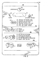
- a faceplate 92 of the controller 60 is shown in Figure 2.
- a power indicator to the controller is shown as 94, and the compressor may be powered by pressing a start switch 95.
- the controller may be placed in the unloaded condition and then stopped by pressing an unloaded stop switch 98. If there is some reason why the compressor must be stopped instantly, then an emergency stop switch 99 may be pressed.
- a graphic display 96 such as an LED, is used to display the controller parameters.
- the parameters are considered as those characteristics which are not directly controllable by the controller during the operation of the compressor.
- the parameters 102 shown on the controller of Figure 2 include operating outlet and sump pressures, difference between the inlet and the sump pressures, total time which the compressor has been running, total time in which the compressor has been running in an unloaded state, and the compressor discharge temperature.
- the graphic display 96 is also used to display the maximum set point of all functions 109.
- the functions are performed by the controller 60 during the operation of the compressor, and include the set on and off line air pressures, the automatic restart time, the maximum discharge air temperature, and the remote start. The operation of these functions will be described later.
- the controller has the capabilities to have a memory and an associated printout. In those instances where the compressor 10 shuts itself off since one of the functions was exceeded but the user is unsure which function it was, the user can analyse the printout to determine which function was exceeded.
- the controller 60 also has a timing capability integral with the printed circuit board 63. Therefore, the controller has the ability to determine how long the compressor has been operating in total and how long the compressor has been operating in an unloaded state.
- the controller 60 also has a modular section 106, by which the mode in which the controller is operating in can be controlled. Due to the timing circuit, the controller 60 has the capability of determining which is the best mode of operation for the compressor to be operating under considering the present state of operation. If the controller is in the on line/off line mode, and the compressor switches between the on and off line positions an established number of times within a specified period (for example three times within three minutes), then the controller will default the compressor to the modulate mode, which would be more suitable considering the operation of the compressor.
- the controller has an unloaded stop switch 98 to place itself in an unloaded condition prior to the time that the compressor fully stops. It is greatly preferred that a compressor be stopped in the unloaded state since if the compressor stops with any pressure in the sump 24, damage could result to the rotors 22 by the pressure in the sump 24 attempting to escape through the rotors.
- the unloaded stop switch 98 operates by turning the compressor to the unloaded state a short period (for example seven seconds), before the compressor is turned off.
- a single pressure transducer or sensor 39 is used to measure more than one pressure since the line/sump solenoid valve switches the pressure which is applied to the transducer input between pressure lines 36 and 62.
- two pressure sensors were required to read the pressures. This multiplicity of pressure sensors not only led to increased expense but also to inconsistent readings.
- the controller 60 also has the capability of calibrating the pressure in the transducer 39 to a known pressure setting. If the transducer is reading a known pressure setting and indicating an incorrect reading, then the controller pressure display can be raised or lowered that amount.
- the thermistor 78 can be similarly calibrated. This not only is helpful to adjust an inaccurate transducer, but also to calibrate the setting when the compressor is brought to a location with a different pressure (due to high altitude, etc.).
- a communication jack 100 is physically and electrically attached to the printed circuit board of the controller such that electrical impulses derived from a computer may be input to affect the controller as described in the computer communications portion of this application.
- the operator of the controller may interface with the controller by pressing various buttons or switches.
- the parameters are shown in a parameter section 102.
- a parameter display tactile membrane button 104 is pressed to select the specific parameter which is to be displayed.
- the mode which the compressor is operating under is controlled by a modular control section 106 of the controller.
- An unload tactile button 108 is pressed to place the compressor in an unload mode.
- the compressor is either placed in a specific mode of operation or the controller selects the most efficient mode of operation depending upon the operation of the compressor.
- the setting of the functions controlled by the controller is regulated within a function section 109.
- the function which is desired to set can be selected by pressing the function set key 111. Once the desired function is set, the function set point may be altered by pressing function step buttons 112 and 114.
- the compressor is programmed to turn itself off after a specific period after the operator has not used the compressor. At this time, an automatic restart indicator 116 will be on. When there is a call for air when the indicator is on, the controller will automatically restart the compressor.
- jacks 100 connected to the controller permits the control and analysis of the controller to originate not only from the operator but also from a computer 118. In this manner, the computer overrides the independent response of the controller to the parameters wherein the controller acts in response to the computer.
- the computer will generate a series of electrical signals which will simulate various known parameters and functions which might be fed to the controller. If the controller displays inconsistent readings or outputs from the output signals, then the inspector will know that the controller is defective.
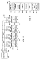
- the computer signal 150 which is generated to each controller contains a plurality of segments.
- a start of transmission segment 152 which signals to all of the controllers connected to the computer that the transmission is about to begin.
- the next segment is a destination address 154 which indicates those controllers that should obey the remainder of the signal.
- the third segment of the signal is a source address 156 which indicates the computer the signal originated from. Since the controller may be programmed to listen to only certain signals, if the source address is incorrect, the controller will not obey a command segment 160 of the signal. Next, a length segment 158 of the signal alerts the controllers how many bytes there will be in the signal.
- the command segment 160 and a data segment 162 combine to tell the specified controller what it should do.
- the command segment indicates which in mode or function the compressor 121, 123, 125 or 127 should operate.
- the data segment if needed for the specific signal, will indicate what temperature, pressure, or other parameter should be obtained by the compressor.
- the check byte sum segment 164 sums the total of all the bytes given in the signal to the controller. If the check byte sum does not agree, then the computer and/or the controller will be alerted that it likely missed a portion of the command. The end of transmission segment indicates that the signal has ended.
- the printed circuit board contains a plurality of input/output jacks 100 such that a plurality of controllers 120, 122, 124, 126, which each operate a separate compressor 121, 123, 125 and 127 can be individually controlled by a single signal from the computer 118. Due to the above signal from the computer, either a single compressor, or any number of compressors can be electrically coupled to operate from the signals from the computer 118.
- the electrical wiring 166 which couples each controller to the computer will be identical.
- the computer is connected to transmission conductor 168 via a computer driver 172 which transmits a signal through conductor 168 to controller receivers 172, 174, 176 and 178 simultaneously.
- each controller 120, 122, 124 and 126 can respond to each inquiring signal from the computer by generating a response signal through controller drivers 180, 182, 184 and 186 which travel through transmission conductor 168 to a computer receiver 188.
- the computer can ask each controller to state its immediate parameters or functions, such as the temperature, pressure that the controller is operating under or how long the individual controller has been operating in an unloaded state.
- the individual controller will respond to the controller with the requested information.
Abstract
Description
- This invention relates to an apparatus for controlling a fluid compression system and more particularly to an electronic control which is used to control and monitor the operation of fluid compression means such as a compressor or pump.
- Previously, fluid compression means have been controlled by electromechanical means. Even though these control means could display the pressure and temperature of the fluid compression means, they could not respond with reliable accuracy or display the pressure or temperature situation prior to an undesired shutdown of the compressor or pump.
- In particular, prior controls for air compressors suffered from the limitations that they could not be operated from a sequencing computer operating over a single line. Also, there was no way to insert a code into the language input to the controls such that the controls would respond to only the correct signals. The prior controls could not have a simulated signal inserted thereinto for the purpose of testing response to simulated parameters.
- According to the present invention, there is provided a fluid compression apparatus comprising compression means including a compressor inlet, a compressor element, a compressor sump and a compressor discharge; a sensor capable of sensing at least one function which relates to the pressure at said compressor discharge; control means, responsive to said sensor, capable of independently controlling said compression means to maintain said discharge pressure within a predetermined range, so as to provide a substantially constant driver speed, the control means controlling the discharge pressure by regulating flow of fluid between the compressor inlet and the compressor sump; and there being a computer for overriding said independent control of said compression means by said control means.
- For a better understanding of the invention and to show how the same may be carried into effect, reference will now be made, by way of example, to the accompanying drawings, in which:-
- Figure 1 is a schematic view illustrating an embodiment of a compressor, with the associated tubing and electrical wiring utilised to operate the compressor, including valves displayed as they would appear in an unloaded state;
- Figure 2 is a view illustrating an embodiment of the controller panel including various controller parameters and controller functions;
- Figure 3 is a diagram illustrating an embodiment of the electrical connections of a plurality of controllers with their compressors to a computer which controls the controllers and compressors; and
- Figure 4 is a block diagram illustrating an arrangement of the computer commands given to the controllers.
- The drawings illustrate an embodiment of the control system for an air compressor. Similar elements are identically numbered throughout the figures.
- It is to be understood that while portions of the specification refer to an air compressor, the present controller could be similarly applied to pumps or any other machine which produces compressed air.
- A compressor controlled by a
controller 60 is shown generally at 10. An inlet valve 12 is closed whenever the pressure in aninlet port 14 exerts a pressure on a piston 16 which overcomes aspring 18. All the air entering the inlet valve has passed through anair filter 20. The air which has passed through the inlet valve is propelled by a compressor driver orrotor 22 into acompressor sump 24. - The
compressor rotor 22 may be rotary, axial or any other well known type. Oil is used both to cool and lubricate therotor 22 and is collected in thesump 24. Aseparator filter 26 removes the oil from the air which has passed through therotor 22 into thesump 24. Air which has passed through thefilter 26 enters acompressor discharge 28. Thedischarge 28 is connected via a minimumpressure check valve 34, anaftercooler 30 and amoisture separator 32 to a user of the compressedair 33. The minimumpressure check valve 34 maintains the pressure in the compressor at a certain pressure (for example 30 psi - 206.9 kN/m²). - The piping system relates to the compressor as follows: The
pressure line 36 is connected to and contains the same pressure as thecompressor discharge 28. Thepressure line 36 connects a line/sump solenoid valve 38 to ashuttle valve 40. Aline 42 connects thecompressure discharge 28 to thesolenoid valve 40. A line 44, which incorporates an unload solenoid valve 46, branches into ablowdown line 50 and aline 48. Theblowdown line 50, when pressurised, opens ablowdown valve 52 and permits the pressure contained within thecompressor discharge 28 to escape via avent line 54 to the atmosphere. - The
vent line 54 may optionally be connected through theair filter 20 to limit the noise of air escaping from thedischarge 28. If the vent line is connected to the filter, however, then a blowdown orifice, not shown, should be included to limit the reverse passage of oil which would otherwise travel from the inlet area to the discharge. - The
line 48 connects via ashuttle valve 51 to aninlet valve line 53. A modulatingline 59, incorporating a modulatingsolenoid valve 56 and a modulating adjustingvalve 58, connects thecompressor discharge 28 to theshuttle valve 51. Whicheverline input valve line 53. - A pressure sensor 39 monitors the pressures of
line 36 andsump line 62, as controlled by the line/sump solenoid valve 38. The controller switches the position of thesolenoid valve 38 several times a second such that both the individual line pressures, and the difference between the two pressures, can be accurately determined. The operation of thecontroller 60 with respect to the line/sump solenoid valves will be described later in this specification. - The
compressor 10 and the associated components may be operated in three modes: unloaded, on line/off line and modulate. The unloaded mode is preferred during the start up of the compressor and when it is desired to limit the output air of the compressor. The on line/off line mode is preferred when the compressor is experiencing a widely varying air demand, as occurs when the user is using an air tool intermittently. The modulate mode is preferably used in those instances where the compressed air demand relative to the compressor capacity is relatively high. - In the unloaded mode, the compressor will not be displacing any air since the inlet valve 12 will be closed. The
controller 60 will open the unload solenoid valve, causing the discharge pressure in thepressure line 36 to be applied through the line 44 to theline 48 and theblowdown line 50. The pressure in theblowdown line 50 will open theblowdown valve 52, venting the pressure in thedischarge 28 viavent line 54 to the atmosphere. Concurrently, the pressure in theline 48 will pass through thevalve 51 andline 53 to theinlet port 14, causing the inlet valve 12 to be closed. - In the on line/off line mode the unload valve 46 will be closed, causing the inlet valve to open permitting the compressor to displace air, and causing the
blowdown valve 52 to close preventing the venting of thecompressor discharge 28 to the atmosphere. However the compressor itself may be shut down to prevent the passage of air through the compressor during the off line mode. - In the modulate mode, the controller will still deactivate the unload valve as described in the prior paragraph, but the modulating
solenoid valve 56 will be open. The pressure in thecompressor discharge 28 will be applied through themodular line 59, thevalve 56 and the modular adjustment valve 58 (where the operator may adjust the pressure via the controller). The discharge pressure will be adjusted by themodular adjustment valve 58 and applied toinput line 53 and theinlet port 14 via thevalve 51. The pressure at which the inlet valve will open will be controlled by the controller. - The
controller 60 indicates which functions and parameters ofcompressor 10, such as temperature and pressure, the operator may select to be displayed, quantitatively displays those functions and parameters, sets the limits of the parameters, and controls thecompressor 10 if the parameters exceed the limits. The following elements are used in the operation of thecontroller 60. - The
controller 60 transmits all of the information to a printedcircuit board 63 via aconductor cable 64. Power is applied to thecontroller 60 from avoltage source 66 via aconductor 68 and theconductor cable 64. - Since the computer feeds signals to the controller which are utilised by the controller, the operation of the controller can be tested by applying a signal having known parameters from the computer to the controller, if the controller responds appropriately to the known signal, then the controller is acceptable for that specific parameter. Otherwise the controller is not operationally acceptable.
- There are several inputs to the printed
circuit board 63. Aconductor 76 connects athermistor 78 to theboard 63. Thethermistor 78 is connected to thesump 24. This thermistor detects the discharge temperature since the temperature at the sump equals the temperature at thedischarge 28. - A
conductor 82 connects the printed circuit board to the pressure sensor 39 and senses the pressures of both thecompressor sump 24 and thecompressor discharge 28. The controller monitors temperature and both pressures at both locations several times a second, to ensure that none of the functions exceed a preset limit (either set by the operator or the manufacturer). - There are also several outputs from the
controller 60, throughconductor tape 64 and the printedcircuit board 63 which control the operation of thecompressor 10. Aconductor 84 connects theboard 63 to the solenoid valve to control whether the pressure sensor will read thesump 24 pressure or thedischarge 28 pressure. - A
conductor 86 connects the board to the unload solenoid valve 46 to control when the valve 46 will open and cause the compressor to enter an unloaded state. When the unload valve opens, theblowdown valve 52 will open, venting the pressure in thecompressor discharge 28 andline 42 to the atmosphere. - A
conductor 88 connects theboard 63 to the modulatingsolenoid valve 56. When thecontroller 60 activates thevalve 56, the compressor will go into the modulating mode and the inlet valve will be controlled by themodular adjustment valve 58. Thevalve 58 connects to theboard 63 via aconductor 90. In this manner, the controller not only determines the operating conditions of the compressor but also controls the operation of the compressor. - A
faceplate 92 of thecontroller 60 is shown in Figure 2. A power indicator to the controller is shown as 94, and the compressor may be powered by pressing astart switch 95. The controller may be placed in the unloaded condition and then stopped by pressing anunloaded stop switch 98. If there is some reason why the compressor must be stopped instantly, then anemergency stop switch 99 may be pressed. - A
graphic display 96, such as an LED, is used to display the controller parameters. The parameters are considered as those characteristics which are not directly controllable by the controller during the operation of the compressor. Theparameters 102 shown on the controller of Figure 2 include operating outlet and sump pressures, difference between the inlet and the sump pressures, total time which the compressor has been running, total time in which the compressor has been running in an unloaded state, and the compressor discharge temperature. - The
graphic display 96 is also used to display the maximum set point of all functions 109. The functions are performed by thecontroller 60 during the operation of the compressor, and include the set on and off line air pressures, the automatic restart time, the maximum discharge air temperature, and the remote start. The operation of these functions will be described later. - The controller has the capabilities to have a memory and an associated printout. In those instances where the
compressor 10 shuts itself off since one of the functions was exceeded but the user is unsure which function it was, the user can analyse the printout to determine which function was exceeded. - The
controller 60 also has a timing capability integral with the printedcircuit board 63. Therefore, the controller has the ability to determine how long the compressor has been operating in total and how long the compressor has been operating in an unloaded state. - The
controller 60 also has amodular section 106, by which the mode in which the controller is operating in can be controlled. Due to the timing circuit, thecontroller 60 has the capability of determining which is the best mode of operation for the compressor to be operating under considering the present state of operation. If the controller is in the on line/off line mode, and the compressor switches between the on and off line positions an established number of times within a specified period (for example three times within three minutes), then the controller will default the compressor to the modulate mode, which would be more suitable considering the operation of the compressor. - The controller has an unloaded
stop switch 98 to place itself in an unloaded condition prior to the time that the compressor fully stops. It is greatly preferred that a compressor be stopped in the unloaded state since if the compressor stops with any pressure in thesump 24, damage could result to therotors 22 by the pressure in thesump 24 attempting to escape through the rotors. The unloadedstop switch 98 operates by turning the compressor to the unloaded state a short period (for example seven seconds), before the compressor is turned off. - If there is some reason why the operator wishes to instantly turn the compressor off, then there is an emergency off
switch 99 which turns the machine off in its loaded state. - A single pressure transducer or sensor 39 is used to measure more than one pressure since the line/sump solenoid valve switches the pressure which is applied to the transducer input between
pressure lines - The
controller 60 also has the capability of calibrating the pressure in the transducer 39 to a known pressure setting. If the transducer is reading a known pressure setting and indicating an incorrect reading, then the controller pressure display can be raised or lowered that amount. Thethermistor 78 can be similarly calibrated. This not only is helpful to adjust an inaccurate transducer, but also to calibrate the setting when the compressor is brought to a location with a different pressure (due to high altitude, etc.). - A
communication jack 100 is physically and electrically attached to the printed circuit board of the controller such that electrical impulses derived from a computer may be input to affect the controller as described in the computer communications portion of this application. - The operator of the controller may interface with the controller by pressing various buttons or switches. The parameters are shown in a
parameter section 102. A parameter displaytactile membrane button 104 is pressed to select the specific parameter which is to be displayed. - The mode which the compressor is operating under is controlled by a
modular control section 106 of the controller. An unloadtactile button 108 is pressed to place the compressor in an unload mode. Depending on the number of times which aload switch 110 is pressed, the compressor is either placed in a specific mode of operation or the controller selects the most efficient mode of operation depending upon the operation of the compressor. - The setting of the functions controlled by the controller is regulated within a
function section 109. The function which is desired to set can be selected by pressing the function set key 111. Once the desired function is set, the function set point may be altered by pressingfunction step buttons - The compressor is programmed to turn itself off after a specific period after the operator has not used the compressor. At this time, an
automatic restart indicator 116 will be on. When there is a call for air when the indicator is on, the controller will automatically restart the compressor. - The use of
jacks 100 connected to the controller permits the control and analysis of the controller to originate not only from the operator but also from acomputer 118. In this manner, the computer overrides the independent response of the controller to the parameters wherein the controller acts in response to the computer. - During the analysis of the controller during manufacturing or after long continued use of the controller, the computer will generate a series of electrical signals which will simulate various known parameters and functions which might be fed to the controller. If the controller displays inconsistent readings or outputs from the output signals, then the inspector will know that the controller is defective.
- The
computer signal 150 which is generated to each controller contains a plurality of segments. A start oftransmission segment 152 which signals to all of the controllers connected to the computer that the transmission is about to begin. The next segment is adestination address 154 which indicates those controllers that should obey the remainder of the signal. - The third segment of the signal is a
source address 156 which indicates the computer the signal originated from. Since the controller may be programmed to listen to only certain signals, if the source address is incorrect, the controller will not obey acommand segment 160 of the signal. Next, alength segment 158 of the signal alerts the controllers how many bytes there will be in the signal. - The
command segment 160 and adata segment 162 combine to tell the specified controller what it should do. The command segment indicates which in mode or function thecompressor - The check
byte sum segment 164 sums the total of all the bytes given in the signal to the controller. If the check byte sum does not agree, then the computer and/or the controller will be alerted that it likely missed a portion of the command. The end of transmission segment indicates that the signal has ended. - The printed circuit board contains a plurality of input/
output jacks 100 such that a plurality ofcontrollers separate compressor computer 118. Due to the above signal from the computer, either a single compressor, or any number of compressors can be electrically coupled to operate from the signals from thecomputer 118. - The
electrical wiring 166 which couples each controller to the computer will be identical. The computer is connected totransmission conductor 168 via acomputer driver 172 which transmits a signal throughconductor 168 tocontroller receivers controller controller drivers transmission conductor 168 to acomputer receiver 188. - With this
electrical wiring system 166 utilising the previously describedsignal 150, the computer can ask each controller to state its immediate parameters or functions, such as the temperature, pressure that the controller is operating under or how long the individual controller has been operating in an unloaded state. The individual controller will respond to the controller with the requested information.
Claims (11)
- A fluid compression apparatus comprising compression means (10) including a compressor inlet, a compressor element (22), a compressor sump (24) and a compressor discharge (28); a sensor (39) capable of sensing at least one function which relates to the pressure at said compressor discharge (28); control means (60), responsive to said sensor, capable of independently controlling said compression means to maintain said discharge pressure within a predetermined range, so as to provide a substantially constant driver speed, the control means controlling the discharge pressure by regulating flow of fluid between the compressor inlet and the compressor sump; and there being a computer (118) for overriding said independent control of said compression means by said control means.
- An apparatus according to claim 1, wherein said at least one function is compressor discharge pressure, and/or compressor discharge temperature, and/or compressor sump pressure, and/or the difference between compressor sump and compressor discharge pressures.
- An apparatus according to claim 1 or 2, wherein said at least one function is automatic restart time which controls how long the period before restart will be after the compressor has been shut down.
- An apparatus according to claim 1, 2 or 3, further comprising an unloaded stop switch (98) which, when actuated, restricts fluid flow through the compressor inlet prior to shutting the compression means off.
- An apparatus according to any one of the preceding claims, wherein there are a plurality of said controllers and the computer is a sequencing computer for alternately controlling the operation of said controllers.
- An apparatus according to claim 5, said computer is arranged to transmit a signal to each of the controllers, and each controller has the capability of determining which portion of the signal applies to that controller.
- An apparatus according to any one of the preceding claims, wherein said computer has a host test function which applies known parameters to the controller (60) to test whether the controller responds properly to the known parameters.
- An apparatus according to claim 6 or claims 6 and 7, wherein the signal includes a destination portion, and/or a task portion, and/or a source address portion, and/or a check byte sum portion, and/or a length command portion, and/or a start of transmission command portion, and/or an end of transmission portion, and/or a data command position.
- A fluid compression apparatus according to claim 1, wherein the compression means (10) is arranged to operate in a first mode in which, after a range defined by upper and lower outlet pressure limits, is set for the discharge pressure, the control means (60) will alter operation of the compression means to cause the discharge pressure to return within the range when the pressure goes outside either limit; and the compression means is arranged to operate in a second mode wherein, after the discharge pressure goes outside either pressure limit, the control means will regulate a predetermined flow of air to the compressor sump while the driver of the compression means maintains substantially constant driver speed to regulate the discharge pressure, and wherein the control means determines which of the first and second modes is more efficient and causes the compression means to operate in that mode.
- An apparatus according to claim 9, wherein when the control means is operating in the first mode of operation and the discharge pressure reaches the lower limit, the control means switches the compression means from an off line to an on line state.
- An apparatus according to claim 9 or 10, wherein when the compression means is in said first mode of operation, and the compression means cycles between an on line and off line state for a predetermined number of cycles within a predetermined period, then the controller means switches the compression means to the second mode of operation.
Applications Claiming Priority (3)
| Application Number | Priority Date | Filing Date | Title |
|---|---|---|---|
| US07/432,115 US5054995A (en) | 1989-11-06 | 1989-11-06 | Apparatus for controlling a fluid compression system |
| US432115 | 1989-11-06 | ||
| PCT/US1990/006406 WO1991006762A1 (en) | 1989-11-06 | 1990-11-02 | Method and apparatus for controlling a fluid compression system |
Publications (2)
| Publication Number | Publication Date |
|---|---|
| EP0502095A1 EP0502095A1 (en) | 1992-09-09 |
| EP0502095B1 true EP0502095B1 (en) | 1995-01-04 |
Family
ID=23714832
Family Applications (1)
| Application Number | Title | Priority Date | Filing Date |
|---|---|---|---|
| EP91900464A Expired - Lifetime EP0502095B1 (en) | 1989-11-06 | 1990-11-02 | Method and apparatus for controlling a fluid compression system |
Country Status (19)
| Country | Link |
|---|---|
| US (1) | US5054995A (en) |
| EP (1) | EP0502095B1 (en) |
| JP (1) | JP3110752B2 (en) |
| CN (1) | CN1051796A (en) |
| AT (1) | ATE116718T1 (en) |
| AU (1) | AU641972B2 (en) |
| BR (1) | BR9007814A (en) |
| CA (1) | CA2073067C (en) |
| DE (1) | DE69015827T2 (en) |
| FI (1) | FI922019A (en) |
| HU (1) | HUT61082A (en) |
| IE (1) | IE903955A1 (en) |
| IL (1) | IL96191A0 (en) |
| MX (1) | MX167337B (en) |
| NZ (1) | NZ235966A (en) |
| PL (1) | PL287645A1 (en) |
| TR (1) | TR25802A (en) |
| WO (1) | WO1991006762A1 (en) |
| ZA (1) | ZA908700B (en) |
Families Citing this family (46)
| Publication number | Priority date | Publication date | Assignee | Title |
|---|---|---|---|---|
| US5352098A (en) * | 1993-04-22 | 1994-10-04 | Ingersoll-Rand Company | Turn valve control system for a rotary screw compressor |
| US5463559A (en) * | 1993-07-19 | 1995-10-31 | Ingersoll-Rand Company | Diagnostic apparatus for an electronic controller |
| US5388968A (en) * | 1994-01-12 | 1995-02-14 | Ingersoll-Rand Company | Compressor inlet valve |
| US5516265A (en) * | 1994-06-14 | 1996-05-14 | Ingersoll-Rand Company | Interface apparatus for permitting microprocessor-based electronic control of non-electronically controlled air compressors |
| FI104205B (en) * | 1994-11-24 | 1999-11-30 | Sarlin Hydor Oy | Method and apparatus for controlling a fluid compression system |
| US5612890A (en) * | 1995-05-19 | 1997-03-18 | F C Systems, Inc. | System and method for controlling product dispensation utilizing metered valve apparatus and electronic interconnection map corresponding to plumbing interconnections |
| DE19606747A1 (en) * | 1996-02-23 | 1997-08-28 | Scharco Elektronik Gmbh & Co K | Display and position equipment industrial controller e.g. for compressor |
| US5626470A (en) * | 1996-04-10 | 1997-05-06 | Ingersoll-Rand Company | Method for providing lubricant to thrust bearing |
| USD387342S (en) * | 1996-05-17 | 1997-12-09 | Ingersoll-Rand Company | Control panel for a microprocessor |
| FI970350A (en) * | 1997-01-28 | 1998-07-29 | Sarlin Hydor Oy | Method and apparatus for controlling a fluid compression system |
| US5967757A (en) * | 1997-03-24 | 1999-10-19 | Gunn; John T. | Compressor control system and method |
| US5967761A (en) * | 1997-07-15 | 1999-10-19 | Ingersoll-Rand Company | Method for modulation lag compressor in multiple compressor system |
| GB9810683D0 (en) * | 1998-05-19 | 1998-07-15 | Elmar Services Limited | Pressure control apparatus |
| DE10120206A1 (en) | 2001-04-24 | 2002-10-31 | Wabco Gmbh & Co Ohg | Method for controlling a compressor |
| FR2849906B1 (en) * | 2003-01-10 | 2006-06-30 | Air Liquide | COMPRESSOR GAS PRODUCTION FACILITY, AND METHOD OF OPERATING THE SAME |
| US8075668B2 (en) | 2005-03-29 | 2011-12-13 | Dresser-Rand Company | Drainage system for compressor separators |
| BE1017162A3 (en) * | 2006-06-09 | 2008-03-04 | Atlas Copco Airpower Nv | DEVICE FOR CONTROLLING WORK PRESSURE OF AN OILY NJECTERED COMPRESSOR INSTALLATION. |
| WO2008036221A2 (en) | 2006-09-19 | 2008-03-27 | Dresser-Rand Company | Rotary separator drum seal |
| MX2009003119A (en) | 2006-09-21 | 2009-04-06 | Dresser Rand Co | Separator drum and compressor impeller assembly. |
| US8267437B2 (en) | 2006-09-25 | 2012-09-18 | Dresser-Rand Company | Access cover for pressurized connector spool |
| WO2008039446A2 (en) | 2006-09-25 | 2008-04-03 | Dresser-Rand Company | Fluid deflector for fluid separator devices |
| WO2008039734A2 (en) | 2006-09-25 | 2008-04-03 | Dresser-Rand Company | Coupling guard system |
| MX2009003178A (en) | 2006-09-25 | 2009-04-03 | Dresser Rand Co | Compressor mounting system. |
| BRPI0717087B1 (en) | 2006-09-25 | 2018-10-16 | Dresser Rand Co | connector spool system for connecting a first component and a second component of an industrial compression system |
| EP2066422B1 (en) | 2006-09-26 | 2012-06-27 | Dresser-Rand Company | Improved static fluid separator device |
| BRPI0705341A2 (en) * | 2007-11-14 | 2009-07-07 | Festo Automacao Ltda | pressure control unit |
| WO2009111616A2 (en) | 2008-03-05 | 2009-09-11 | Dresser-Rand Company | Compressor assembly including separator and ejector pump |
| US8062400B2 (en) | 2008-06-25 | 2011-11-22 | Dresser-Rand Company | Dual body drum for rotary separators |
| US7922218B2 (en) | 2008-06-25 | 2011-04-12 | Dresser-Rand Company | Shear ring casing coupler device |
| US8079805B2 (en) | 2008-06-25 | 2011-12-20 | Dresser-Rand Company | Rotary separator and shaft coupler for compressors |
| US8087901B2 (en) | 2009-03-20 | 2012-01-03 | Dresser-Rand Company | Fluid channeling device for back-to-back compressors |
| US8210804B2 (en) | 2009-03-20 | 2012-07-03 | Dresser-Rand Company | Slidable cover for casing access port |
| US8061972B2 (en) | 2009-03-24 | 2011-11-22 | Dresser-Rand Company | High pressure casing access cover |
| WO2011034764A2 (en) | 2009-09-15 | 2011-03-24 | Dresser-Rand Company | Improved density-based compact separator |
| BR112012020085B1 (en) | 2010-02-10 | 2020-12-01 | Dresser-Rand Company | collection device for a separator and separation method |
| WO2012009158A2 (en) | 2010-07-15 | 2012-01-19 | Dresser-Rand Company | Enhanced in-line rotary separator |
| US8663483B2 (en) | 2010-07-15 | 2014-03-04 | Dresser-Rand Company | Radial vane pack for rotary separators |
| WO2012012018A2 (en) | 2010-07-20 | 2012-01-26 | Dresser-Rand Company | Combination of expansion and cooling to enhance separation |
| US8821362B2 (en) | 2010-07-21 | 2014-09-02 | Dresser-Rand Company | Multiple modular in-line rotary separator bundle |
| EP2614216B1 (en) | 2010-09-09 | 2017-11-15 | Dresser-Rand Company | Flush-enabled controlled flow drain |
| US20130245840A1 (en) * | 2012-03-16 | 2013-09-19 | Gerard S. Lazzara | Modulated Reset Relief Valve |
| US20130294887A1 (en) * | 2012-05-01 | 2013-11-07 | General Electric Company | Gas turbine air processing system |
| US20150275897A1 (en) * | 2012-09-21 | 2015-10-01 | Sandvik Surface Mining | Method and apparatus for decompressing a compressor |
| KR101790545B1 (en) | 2013-02-08 | 2017-10-26 | 가부시키가이샤 히다치 산키시스템 | Fluid compression system and control device therefor |
| EP3334934B1 (en) | 2015-08-14 | 2021-08-04 | Sarlin OY AB | System for the control of a compression system |
| JP7384860B2 (en) * | 2021-06-28 | 2023-11-21 | 本田技研工業株式会社 | Depressurization system and method |
Family Cites Families (29)
| Publication number | Priority date | Publication date | Assignee | Title |
|---|---|---|---|---|
| SE333210B (en) * | 1969-07-17 | 1971-03-08 | Atlas Copco Ab | CONTROL DEVICE FOR MOTOR-DRIVEN COMPRESSORS WITH MORE ONE STEP AND WHEN THE POWER TRANSFERRED BY THE ENGINE TO THE COMPRESSOR CHANGES DUE TO THE CHANGE OF THE PRESSURE ON THE PRESSURE SIDE OF THE COMPRESSOR |
| US3574474A (en) * | 1969-07-31 | 1971-04-13 | Carrier Corp | Method of and apparatus for controlling the operation of gas compression apparatus |
| US3860363A (en) * | 1973-05-10 | 1975-01-14 | Chicago Pneumatic Tool Co | Rotary compressor having improved control system |
| US3876326A (en) * | 1974-01-30 | 1975-04-08 | Simmonds Precision Products | Surge control system |
| US3963367A (en) * | 1974-08-21 | 1976-06-15 | International Harvester Company | Turbine surge detection system |
| US4005581A (en) * | 1975-01-24 | 1977-02-01 | Westinghouse Electric Corporation | Method and apparatus for controlling a steam turbine |
| US4156578A (en) * | 1977-08-02 | 1979-05-29 | Agar Instrumentation Incorporated | Control of centrifugal compressors |
| JPS556118A (en) * | 1978-06-26 | 1980-01-17 | Sharp Corp | Control panel for microwave oven |
| US4227862A (en) * | 1978-09-19 | 1980-10-14 | Frick Company | Solid state compressor control system |
| US4236379A (en) * | 1979-01-04 | 1980-12-02 | Honeywell Inc. | Heat pump compressor crankcase low differential temperature detection and control system |
| US4413314A (en) * | 1980-06-16 | 1983-11-01 | Forney Engineering Company | Industrial process control system |
| US4439997A (en) * | 1981-03-16 | 1984-04-03 | Cantley Robert J | Energy management system for multi stage refrigeration systems |
| DE3213155A1 (en) * | 1982-04-08 | 1983-10-13 | VIA Gesellschaft für Verfahrenstechnik mbH, 4000 Düsseldorf | Method for the monitoring of a compressed air generating system and device for carrying out the method |
| US4595342A (en) * | 1982-05-29 | 1986-06-17 | Jan Christlieb | Device for the control of a fluid pressure of a turbomachine engine and support for a pressure pick-off |
| US4535401A (en) * | 1982-06-30 | 1985-08-13 | Texas Instruments Incorporated | Apparatus and method for providing power from master controller to subcontrollers and data communication therebetween |
| JPS5960522A (en) * | 1982-09-30 | 1984-04-06 | Canon Inc | Electronic apparatus |
| FI73315C (en) * | 1984-06-15 | 1987-09-10 | Nokia Oy Ab | Calibration system for calibration of mass flow regulators. |
| JPS6144034A (en) * | 1984-08-07 | 1986-03-03 | Omron Tateisi Electronics Co | Switch control device in vehicle |
| US4706470A (en) * | 1985-05-16 | 1987-11-17 | Sawafuji Electric Co., Ltd. | System for controlling compressor operation |
| US4707470A (en) * | 1985-05-17 | 1987-11-17 | Smithkline Beckman Corporation | Polyene antibiotic emulsion formulation |
| JPS6248999A (en) * | 1985-08-27 | 1987-03-03 | Idemitsu Petrochem Co Ltd | Method for operating compressor |
| DE3544822A1 (en) * | 1985-12-18 | 1987-06-19 | Gutehoffnungshuette Man | METHOD FOR CONTROLLING PUMP LIMITS OF TURBO COMPRESSORS |
| US4646528A (en) * | 1985-12-27 | 1987-03-03 | Whirlpool Corporation | Temperature set point control for a refrigerator |
| US4807150A (en) * | 1986-10-02 | 1989-02-21 | Phillips Petroleum Company | Constraint control for a compressor system |
| US4791258A (en) * | 1987-07-31 | 1988-12-13 | Hamilton Standard Controls, Inc. | Sealed enclosure for electrical circuitry in moist environment |
| FR2634254B1 (en) * | 1988-07-14 | 1993-05-21 | Ecoair Drucklufttechnik | METHOD FOR CONTROLLING A COMPRESSOR AND CONTROL DEVICE |
| DE3919407A1 (en) * | 1988-07-14 | 1990-01-18 | Eco Air Drucklufttechnik Gmbh | METHOD FOR CONTROLLING A COMPRESSOR AND CONTROL DEVICE |
| FI83808C (en) * | 1988-10-05 | 1991-08-26 | Tampella Oy Ab | Method for controlling air production in a screw compressor |
| US4899338A (en) * | 1988-12-15 | 1990-02-06 | Chrysler Motors Corporation | Electrical device command system, single wire bus and smart octal controller arrangement therefor |
-
1989
- 1989-11-06 US US07/432,115 patent/US5054995A/en not_active Expired - Lifetime
-
1990
- 1990-10-30 ZA ZA908700A patent/ZA908700B/en unknown
- 1990-10-31 IL IL96191A patent/IL96191A0/en unknown
- 1990-11-02 AT AT91900464T patent/ATE116718T1/en not_active IP Right Cessation
- 1990-11-02 JP JP03501045A patent/JP3110752B2/en not_active Expired - Fee Related
- 1990-11-02 IE IE395590A patent/IE903955A1/en unknown
- 1990-11-02 BR BR909007814A patent/BR9007814A/en not_active IP Right Cessation
- 1990-11-02 WO PCT/US1990/006406 patent/WO1991006762A1/en active IP Right Grant
- 1990-11-02 AU AU69028/91A patent/AU641972B2/en not_active Ceased
- 1990-11-02 HU HU9201507A patent/HUT61082A/en unknown
- 1990-11-02 CA CA002073067A patent/CA2073067C/en not_active Expired - Fee Related
- 1990-11-02 DE DE69015827T patent/DE69015827T2/en not_active Expired - Fee Related
- 1990-11-02 EP EP91900464A patent/EP0502095B1/en not_active Expired - Lifetime
- 1990-11-05 MX MX023165A patent/MX167337B/en unknown
- 1990-11-05 NZ NZ235966A patent/NZ235966A/en unknown
- 1990-11-06 CN CN90109059A patent/CN1051796A/en active Pending
- 1990-11-06 TR TR90/1051A patent/TR25802A/en unknown
- 1990-11-06 PL PL28764590A patent/PL287645A1/en unknown
-
1992
- 1992-05-05 FI FI922019A patent/FI922019A/en not_active Application Discontinuation
Also Published As
| Publication number | Publication date |
|---|---|
| PL287645A1 (en) | 1991-07-29 |
| DE69015827D1 (en) | 1995-02-16 |
| BR9007814A (en) | 1992-09-01 |
| JPH05506070A (en) | 1993-09-02 |
| DE69015827T2 (en) | 1995-08-03 |
| HU9201507D0 (en) | 1992-08-28 |
| IE903955A1 (en) | 1991-05-08 |
| WO1991006762A1 (en) | 1991-05-16 |
| CA2073067C (en) | 1995-11-21 |
| ATE116718T1 (en) | 1995-01-15 |
| JP3110752B2 (en) | 2000-11-20 |
| FI922019A0 (en) | 1992-05-05 |
| CA2073067A1 (en) | 1991-05-07 |
| IL96191A0 (en) | 1991-07-18 |
| NZ235966A (en) | 1993-04-28 |
| MX167337B (en) | 1993-03-17 |
| CN1051796A (en) | 1991-05-29 |
| FI922019A (en) | 1992-05-05 |
| TR25802A (en) | 1993-09-01 |
| ZA908700B (en) | 1991-09-25 |
| HUT61082A (en) | 1992-11-30 |
| EP0502095A1 (en) | 1992-09-09 |
| US5054995A (en) | 1991-10-08 |
| AU641972B2 (en) | 1993-10-07 |
| AU6902891A (en) | 1991-05-31 |
Similar Documents
| Publication | Publication Date | Title |
|---|---|---|
| EP0502095B1 (en) | Method and apparatus for controlling a fluid compression system | |
| EP1209427B1 (en) | Air-conditioning servicing system and method | |
| EP0570114B1 (en) | Control system for prime driver of compressor and method | |
| EP0904573B1 (en) | A method for surveying the condition of a control valve, and a valve apparatus | |
| US6119047A (en) | Transmitter with software for determining when to initiate diagnostics | |
| US6045331A (en) | Fluid pump speed controller | |
| EP1370770B1 (en) | Modular system for the control of compression systems | |
| US6273686B1 (en) | Apparatus and method for controlling a rated system pressure | |
| US4174729A (en) | Pressure sensing safety device | |
| CA2163572A1 (en) | System and methods for controlling rotary screw compressors | |
| US4969801A (en) | Method and apparatus for shutting off a compressor when it rotates in reverse direction | |
| US6123510A (en) | Method for controlling fluid flow through a compressed fluid system | |
| US5550460A (en) | Voltage regulator control system with multiple control programs | |
| MXPA04006518A (en) | Target tire pressure learning method. | |
| GB2327750A (en) | Burner control installation | |
| KR940002886B1 (en) | Method of and apparatus for detecting predicted failure in fluid-pressure system | |
| US5046924A (en) | Process and circuit arrangement for controlling a consumer driven by an internal combustion engine | |
| US7975498B2 (en) | Intelligent controller for refrigerating and air conditioning systems | |
| US20180306188A1 (en) | Compressor provided with an electronic pressure switch and method of regulating the pressure within such a compressor | |
| US5874895A (en) | Method and apparatus for testing operation of a sensor controlled device | |
| US5545974A (en) | Variamp oil temperature control | |
| CN205207143U (en) | Air compressor's testing equipment | |
| CA1058129A (en) | Control system for variable capacity gas compressor | |
| JPH0620165Y2 (en) | Pressure reducing valve | |
| JPH07230319A (en) | Detecting method for wiring abnormality of servo controller system |
Legal Events
| Date | Code | Title | Description |
|---|---|---|---|
| PUAI | Public reference made under article 153(3) epc to a published international application that has entered the european phase |
Free format text: ORIGINAL CODE: 0009012 |
|
| 17P | Request for examination filed |
Effective date: 19920518 |
|
| AK | Designated contracting states |
Kind code of ref document: A1 Designated state(s): AT BE CH DE DK ES FR GB GR IT LI LU NL SE |
|
| 17Q | First examination report despatched |
Effective date: 19931008 |
|
| GRAA | (expected) grant |
Free format text: ORIGINAL CODE: 0009210 |
|
| AK | Designated contracting states |
Kind code of ref document: B1 Designated state(s): AT BE CH DE DK ES FR GB GR IT LI LU NL SE |
|
| PG25 | Lapsed in a contracting state [announced via postgrant information from national office to epo] |
Ref country code: NL Effective date: 19950104 Ref country code: LI Effective date: 19950104 Ref country code: GR Free format text: LAPSE BECAUSE OF FAILURE TO SUBMIT A TRANSLATION OF THE DESCRIPTION OR TO PAY THE FEE WITHIN THE PRESCRIBED TIME-LIMIT Effective date: 19950104 Ref country code: ES Free format text: THE PATENT HAS BEEN ANNULLED BY A DECISION OF A NATIONAL AUTHORITY Effective date: 19950104 Ref country code: DK Effective date: 19950104 Ref country code: CH Effective date: 19950104 Ref country code: AT Effective date: 19950104 |
|
| REF | Corresponds to: |
Ref document number: 116718 Country of ref document: AT Date of ref document: 19950115 Kind code of ref document: T |
|
| EAL | Se: european patent in force in sweden |
Ref document number: 91900464.8 |
|
| REF | Corresponds to: |
Ref document number: 69015827 Country of ref document: DE Date of ref document: 19950216 |
|
| ITF | It: translation for a ep patent filed |
Owner name: JACOBACCI & PERANI S.P.A. |
|
| ET | Fr: translation filed | ||
| REG | Reference to a national code |
Ref country code: CH Ref legal event code: PL |
|
| NLV1 | Nl: lapsed or annulled due to failure to fulfill the requirements of art. 29p and 29m of the patents act | ||
| PLBE | No opposition filed within time limit |
Free format text: ORIGINAL CODE: 0009261 |
|
| STAA | Information on the status of an ep patent application or granted ep patent |
Free format text: STATUS: NO OPPOSITION FILED WITHIN TIME LIMIT |
|
| PG25 | Lapsed in a contracting state [announced via postgrant information from national office to epo] |
Ref country code: LU Free format text: LAPSE BECAUSE OF NON-PAYMENT OF DUE FEES Effective date: 19951130 |
|
| 26N | No opposition filed | ||
| REG | Reference to a national code |
Ref country code: GB Ref legal event code: IF02 |
|
| PGFP | Annual fee paid to national office [announced via postgrant information from national office to epo] |
Ref country code: SE Payment date: 20021018 Year of fee payment: 13 |
|
| PG25 | Lapsed in a contracting state [announced via postgrant information from national office to epo] |
Ref country code: SE Free format text: LAPSE BECAUSE OF NON-PAYMENT OF DUE FEES Effective date: 20031103 |
|
| EUG | Se: european patent has lapsed | ||
| PGFP | Annual fee paid to national office [announced via postgrant information from national office to epo] |
Ref country code: GB Payment date: 20041027 Year of fee payment: 15 |
|
| PGFP | Annual fee paid to national office [announced via postgrant information from national office to epo] |
Ref country code: FR Payment date: 20041119 Year of fee payment: 15 |
|
| PGFP | Annual fee paid to national office [announced via postgrant information from national office to epo] |
Ref country code: BE Payment date: 20041216 Year of fee payment: 15 |
|
| PGFP | Annual fee paid to national office [announced via postgrant information from national office to epo] |
Ref country code: DE Payment date: 20041230 Year of fee payment: 15 |
|
| PG25 | Lapsed in a contracting state [announced via postgrant information from national office to epo] |
Ref country code: IT Free format text: LAPSE BECAUSE OF NON-PAYMENT OF DUE FEES Effective date: 20051102 Ref country code: GB Free format text: LAPSE BECAUSE OF NON-PAYMENT OF DUE FEES Effective date: 20051102 |
|
| PG25 | Lapsed in a contracting state [announced via postgrant information from national office to epo] |
Ref country code: BE Free format text: LAPSE BECAUSE OF NON-PAYMENT OF DUE FEES Effective date: 20051130 |
|
| PG25 | Lapsed in a contracting state [announced via postgrant information from national office to epo] |
Ref country code: DE Free format text: LAPSE BECAUSE OF NON-PAYMENT OF DUE FEES Effective date: 20060601 |
|
| GBPC | Gb: european patent ceased through non-payment of renewal fee |
Effective date: 20051102 |
|
| PG25 | Lapsed in a contracting state [announced via postgrant information from national office to epo] |
Ref country code: FR Free format text: LAPSE BECAUSE OF NON-PAYMENT OF DUE FEES Effective date: 20060731 |
|
| REG | Reference to a national code |
Ref country code: FR Ref legal event code: ST Effective date: 20060731 |
|
| BERE | Be: lapsed |
Owner name: *INGERSOLL-RAND CY Effective date: 20051130 |