EP0502277A2 - Fiber optic ear thermometer - Google Patents
Fiber optic ear thermometer Download PDFInfo
- Publication number
- EP0502277A2 EP0502277A2 EP91310451A EP91310451A EP0502277A2 EP 0502277 A2 EP0502277 A2 EP 0502277A2 EP 91310451 A EP91310451 A EP 91310451A EP 91310451 A EP91310451 A EP 91310451A EP 0502277 A2 EP0502277 A2 EP 0502277A2
- Authority
- EP
- European Patent Office
- Prior art keywords
- temperature
- signal
- sheath
- ear thermometer
- thermopile
- Prior art date
- Legal status (The legal status is an assumption and is not a legal conclusion. Google has not performed a legal analysis and makes no representation as to the accuracy of the status listed.)
- Withdrawn
Links
- 239000000835 fiber Substances 0.000 title claims abstract description 24
- 210000003454 tympanic membrane Anatomy 0.000 claims abstract description 21
- 230000005855 radiation Effects 0.000 claims abstract description 20
- 210000000613 ear canal Anatomy 0.000 claims abstract description 11
- 238000009529 body temperature measurement Methods 0.000 claims abstract description 5
- 239000000523 sample Substances 0.000 claims description 37
- 239000013307 optical fiber Substances 0.000 claims description 18
- 239000004973 liquid crystal related substance Substances 0.000 claims description 8
- 239000005387 chalcogenide glass Substances 0.000 claims description 3
- 230000005672 electromagnetic field Effects 0.000 claims description 3
- 238000004519 manufacturing process Methods 0.000 claims description 3
- 230000011664 signaling Effects 0.000 claims 2
- 230000005540 biological transmission Effects 0.000 abstract description 3
- 238000012864 cross contamination Methods 0.000 abstract description 2
- 230000000977 initiatory effect Effects 0.000 abstract 1
- 238000005259 measurement Methods 0.000 description 13
- 238000010586 diagram Methods 0.000 description 6
- 239000004033 plastic Substances 0.000 description 6
- 229920003023 plastic Polymers 0.000 description 6
- 238000000034 method Methods 0.000 description 5
- 238000003825 pressing Methods 0.000 description 5
- 238000003780 insertion Methods 0.000 description 4
- 230000037431 insertion Effects 0.000 description 4
- 229910052751 metal Inorganic materials 0.000 description 4
- 239000002184 metal Substances 0.000 description 4
- 210000000664 rectum Anatomy 0.000 description 4
- 238000005516 engineering process Methods 0.000 description 3
- 239000011521 glass Substances 0.000 description 3
- 238000009413 insulation Methods 0.000 description 3
- 239000004698 Polyethylene Substances 0.000 description 2
- 238000010521 absorption reaction Methods 0.000 description 2
- 238000001914 filtration Methods 0.000 description 2
- 239000013305 flexible fiber Substances 0.000 description 2
- 210000003016 hypothalamus Anatomy 0.000 description 2
- 238000009434 installation Methods 0.000 description 2
- 239000000463 material Substances 0.000 description 2
- -1 polyethylene Polymers 0.000 description 2
- 229920000573 polyethylene Polymers 0.000 description 2
- 238000002310 reflectometry Methods 0.000 description 2
- 238000009966 trimming Methods 0.000 description 2
- 230000002411 adverse Effects 0.000 description 1
- 239000008280 blood Substances 0.000 description 1
- 210000004369 blood Anatomy 0.000 description 1
- 230000036760 body temperature Effects 0.000 description 1
- 210000000269 carotid artery external Anatomy 0.000 description 1
- 239000011248 coating agent Substances 0.000 description 1
- 238000000576 coating method Methods 0.000 description 1
- 238000001816 cooling Methods 0.000 description 1
- 238000012937 correction Methods 0.000 description 1
- 230000000881 depressing effect Effects 0.000 description 1
- 238000003745 diagnosis Methods 0.000 description 1
- 230000000694 effects Effects 0.000 description 1
- 239000006260 foam Substances 0.000 description 1
- PCHJSUWPFVWCPO-UHFFFAOYSA-N gold Chemical compound [Au] PCHJSUWPFVWCPO-UHFFFAOYSA-N 0.000 description 1
- 239000010931 gold Substances 0.000 description 1
- 229910052737 gold Inorganic materials 0.000 description 1
- 238000001746 injection moulding Methods 0.000 description 1
- 238000002955 isolation Methods 0.000 description 1
- QSHDDOUJBYECFT-UHFFFAOYSA-N mercury Chemical compound [Hg] QSHDDOUJBYECFT-UHFFFAOYSA-N 0.000 description 1
- 229910052753 mercury Inorganic materials 0.000 description 1
- 230000002093 peripheral effect Effects 0.000 description 1
- 238000007711 solidification Methods 0.000 description 1
- 230000008023 solidification Effects 0.000 description 1
- 230000001954 sterilising effect Effects 0.000 description 1
- 238000004659 sterilization and disinfection Methods 0.000 description 1
- 230000002277 temperature effect Effects 0.000 description 1
- 238000004861 thermometry Methods 0.000 description 1
- 230000026683 transduction Effects 0.000 description 1
- 238000010361 transduction Methods 0.000 description 1
Images


Classifications
-
- G—PHYSICS
- G01—MEASURING; TESTING
- G01J—MEASUREMENT OF INTENSITY, VELOCITY, SPECTRAL CONTENT, POLARISATION, PHASE OR PULSE CHARACTERISTICS OF INFRARED, VISIBLE OR ULTRAVIOLET LIGHT; COLORIMETRY; RADIATION PYROMETRY
- G01J5/00—Radiation pyrometry, e.g. infrared or optical thermometry
- G01J5/02—Constructional details
- G01J5/04—Casings
-
- G—PHYSICS
- G01—MEASURING; TESTING
- G01J—MEASUREMENT OF INTENSITY, VELOCITY, SPECTRAL CONTENT, POLARISATION, PHASE OR PULSE CHARACTERISTICS OF INFRARED, VISIBLE OR ULTRAVIOLET LIGHT; COLORIMETRY; RADIATION PYROMETRY
- G01J5/00—Radiation pyrometry, e.g. infrared or optical thermometry
- G01J5/02—Constructional details
- G01J5/025—Interfacing a pyrometer to an external device or network; User interface
-
- G—PHYSICS
- G01—MEASURING; TESTING
- G01J—MEASUREMENT OF INTENSITY, VELOCITY, SPECTRAL CONTENT, POLARISATION, PHASE OR PULSE CHARACTERISTICS OF INFRARED, VISIBLE OR ULTRAVIOLET LIGHT; COLORIMETRY; RADIATION PYROMETRY
- G01J5/00—Radiation pyrometry, e.g. infrared or optical thermometry
- G01J5/02—Constructional details
- G01J5/04—Casings
- G01J5/049—Casings for tympanic thermometers
-
- G—PHYSICS
- G01—MEASURING; TESTING
- G01J—MEASUREMENT OF INTENSITY, VELOCITY, SPECTRAL CONTENT, POLARISATION, PHASE OR PULSE CHARACTERISTICS OF INFRARED, VISIBLE OR ULTRAVIOLET LIGHT; COLORIMETRY; RADIATION PYROMETRY
- G01J5/00—Radiation pyrometry, e.g. infrared or optical thermometry
- G01J5/02—Constructional details
- G01J5/05—Means for preventing contamination of the components of the optical system; Means for preventing obstruction of the radiation path
-
- G—PHYSICS
- G01—MEASURING; TESTING
- G01J—MEASUREMENT OF INTENSITY, VELOCITY, SPECTRAL CONTENT, POLARISATION, PHASE OR PULSE CHARACTERISTICS OF INFRARED, VISIBLE OR ULTRAVIOLET LIGHT; COLORIMETRY; RADIATION PYROMETRY
- G01J5/00—Radiation pyrometry, e.g. infrared or optical thermometry
- G01J5/02—Constructional details
- G01J5/06—Arrangements for eliminating effects of disturbing radiation; Arrangements for compensating changes in sensitivity
- G01J5/064—Ambient temperature sensor; Housing temperature sensor; Constructional details thereof
-
- G—PHYSICS
- G01—MEASURING; TESTING
- G01J—MEASUREMENT OF INTENSITY, VELOCITY, SPECTRAL CONTENT, POLARISATION, PHASE OR PULSE CHARACTERISTICS OF INFRARED, VISIBLE OR ULTRAVIOLET LIGHT; COLORIMETRY; RADIATION PYROMETRY
- G01J5/00—Radiation pyrometry, e.g. infrared or optical thermometry
- G01J5/02—Constructional details
- G01J5/08—Optical arrangements
- G01J5/0818—Waveguides
- G01J5/0821—Optical fibres
-
- G—PHYSICS
- G01—MEASURING; TESTING
- G01J—MEASUREMENT OF INTENSITY, VELOCITY, SPECTRAL CONTENT, POLARISATION, PHASE OR PULSE CHARACTERISTICS OF INFRARED, VISIBLE OR ULTRAVIOLET LIGHT; COLORIMETRY; RADIATION PYROMETRY
- G01J5/00—Radiation pyrometry, e.g. infrared or optical thermometry
- G01J5/10—Radiation pyrometry, e.g. infrared or optical thermometry using electric radiation detectors
- G01J5/12—Radiation pyrometry, e.g. infrared or optical thermometry using electric radiation detectors using thermoelectric elements, e.g. thermocouples
- G01J5/14—Electrical features thereof
- G01J5/16—Arrangements with respect to the cold junction; Compensating influence of ambient temperature or other variables
-
- G—PHYSICS
- G01—MEASURING; TESTING
- G01J—MEASUREMENT OF INTENSITY, VELOCITY, SPECTRAL CONTENT, POLARISATION, PHASE OR PULSE CHARACTERISTICS OF INFRARED, VISIBLE OR ULTRAVIOLET LIGHT; COLORIMETRY; RADIATION PYROMETRY
- G01J5/00—Radiation pyrometry, e.g. infrared or optical thermometry
- G01J5/70—Passive compensation of pyrometer measurements, e.g. using ambient temperature sensing or sensing of temperature within housing
Definitions
- thermometers intended to measure the core temperature of a living being and, more specifically, to measure that temperature by measuring and analyzing infrared radiation from the tympanic membrane.
- thermometers The measurement of the core temperature of a body has been long used in medical diagnosis and treatment.
- the most common method has been to measure temperature with a tubular glass thermometer containing mercury by insertion in the mouth or rectum, placing under the arm, etc. Breakage of those thermometers in use is a constant danger.
- ill or injured patients may bite through the thermometer or make abrupt movements which cause breakage during the 2-3 minutes required to obtain an accurate maximum temperature.
- mouth or rectum temperatures may not always be representative of true body core temperature and do not change as rapidly as core temperature.
- These thermometers require sterilization when used with a number of patients to prevent cross-contamination and must be shaken down to reduce the displayed temperature since they only measure increasing temperature. These steps take significant time in a busy medical office or hospital and may be overlooked with serious consequences.
- the tympanic membrane within the ear canal is an excellent site for determination of the core temperature of a body due to its proximity to the external carotid artery which supplies blood to the hypothalamus.
- the hypothalamus has been shown to be the site of the body's core temperature. Patients show changes in core temperature at the tympanic membrane prior to peripheral sites such as the mouth or rectum. This allows the attending physician to more quickly respond to possible complications.
- Prior ear thermometers suffer from a number of problems. They are difficult to calibrate to provide accurate temperatures in varying ambient temperature conditions and have repeatability problems.
- the previous ear thermometers used rigid metal tube "waveguides" using a metal coating such as gold to increase the reflectivity of the inner surface. Since these work according to principles of classic optics with the infrared radiation bouncing off the walls from one end to the other there are severe losses with a tube of the necessary length. For example, assuming a reflectivity of 97%, 20 "bounces" will reduce the signal by about 50%. The tube must be straight and must have a large diameter to reduce the number of bounces. Typical of such ear thermometers is that described by Fraden in U.S. Patent 4,797,840.
- thermometer Another prior ear thermometer is described by O'Hara et al in U.S. Patent 4,790,324.
- This thermometer uses a probe including waveguide tube to direct infrared radiation to a thermopile which is kept at a constant temperature by a heater.
- the probe is connected to a chopper unit which is kept at a constant temperature by a second heater system to establish a reference temperature. Then the probe is removed from the chopper, a disposable speculum is placed over the probe which is then inserted in the patient's ear and a temperature reading is taken.
- This complex calibration method is prone to errors, requires several heaters and may give erroneous readings if the calibration targets are not at the precise intended temperatures or there is a delay between calibration and ear temperature measurement.
- thermometers of improved simplicity, accuracy and usefulness.
- Another object of this invention is to provide an improved, low-loss, means for conveying infrared radiation from the tympanic membrane to a temperature detector.
- Still another object is to provide an ear thermometer of improved accuracy and resistance to errors resulting from varying ambient conditions.
- a further object is to provide an ear thermometer capable of accurate compensation or nulling of extraneous signals immediately prior or immediately after temperature measurement.
- Yet another object is to provide an improved disposable sheath for the probe of an ear thermometer.
- an ear thermometer which includes a probe for insertion into the ear to a location adjacent to, but not in contact with, the tympanic membrane, an infrared radiation transmitting flexible fiber optic light guide within the probe for transmitting infrared radiation emitted by the tympanic membrane to a thermopile in an adjacent housing, a disposable sheath over the probe having an infrared transparent window portion covering the fiber optic end, electronic circuitry in the housing to compensate for ambient temperature variations, detector drift, etc. and provide an accurate temperature readout and a display for indicating the temperature measured.
- the unit may have any suitable configuration.
- a "pistol grip" shape has been found to be convenient, with the electronic components and batteries in the handle.
- the flexible fiber optic light guide allows placement of the detector in the body of the handpiece to allow better thermal and electrical shielding of the detector.
- the fibers have a small numerical aperture so they look at only the tympanic membrane and do not transmit radiation from surrounding ear tissue. Since the fiber optic has very low transmission losses, a longer transmission path may be used and a smaller detector may be used for lower noise.
- thermometer is a self-contained, battery powered unit. If rechargeable batteries are used, the unit may be stored between uses in a recharger stand which may have an attached container for a supply of disposable probe sheaths. The unit is easily portable, typically being carried in a small case with a supply of sheaths.
- a housing 10 contains the electronic and other components and bears a probe 12 and a temperature readout display 14.
- Display 14 is typically a conventional liquid crystal display. The temperature is displayed in relatively large characters on either the celsius or fahrenheit scales.
- Display 14 also typically shows the mode, typically oral, rectal, tympanic or scan, "ready” to indicate that the system is ready for use, “calibrate” during the (very short) system calibration cycle and power supply status (typically “recharge” when a rechargeable battery requires recharging prior to use and a bar scale indicating the extent of charge from empty to full).
- the display 14 provides system status under the direction of a microprocessor. Other system characteristics may be displayed, if desired. Alternatively, a single display line, capable of showing 8 characters, may be used to selectively or in sequence display the "ready", “calibrate”, etc., displays, if desired.
- housing may have any suitable configuration, the "pistol" shape shown is preferred for ease of use.
- the user's hand surrounds the lower portion of housing 10, leaving display area 14 visible, and probe 12 is inserted into the ear canal.
- a disposable sheath 16 shown in Figure 2 covers the end of probe 12 and is shaped to permit the desired insertion distance so that the end of probe 12 is near, but not in contact, with the tympanic membrane.
- a trigger switch 18 is pressed to begin the temperature calibration and measurement sequence.
- a pair of mode switches 15 and 17 that allow the operator to toggle from one mode to another are located above display 14.
- the central area of display 14, the area below switches 15 and 17 in Figure 1b, is shown in enlarged detail in Figure 6.
- Depressing switch 17 a single time when in the tympanic mode causes the device to change to the scan mode, showing the temperature adjacent to the detector. Pressing switch 17 twice when in the tympanic mode changes to the oral mode, while pressing switch an additional time moves to the rectal mode.
- the scan, oral and rectal displays are simply equivalents that one would expect to correspond to the tympanic reading obtained. These are for the convenience of clinicians who normally use the oral or rectal method of thermometry.
- the mode in use is shown in area 13 in Figure 6, as are displays indicating that the calibration sequence is in progress, that the battery is being recharged and the unit is on and "ready". While all of these indicia are shown together in Figure 6, if liquid crystal display means are used, only the active one of these display words will be shown at a time.
- Pressing switch 15 twice changes the reading from Fahrenheit to Celsius and lights the "°C” instead of the "°F” on the display as shown. To recall the last five temperature readings, switch 15 is pressed once, then switch 17 is pressed once. The last five temperature readings are stepped through by pressing switch 15 repeatedly and displayed at area 23. Which of the last five readings is displayed is indicated by numbers 25 (only one of which is displayed at a time). Pressing trigger switch 18 returns to the default settings and displays the last reading taken.
- the display also preferably includes a conventional bar shaped liquid crystal display 19 connected to battery 24 so as to indicate battery condition from fully discharged to fully charged by increasing bar length. Also, an audible alarm 21 (as seen in Figure 1b) is preferably included to signal very low battery condition with suitable conventional connections to battery 24.
- the internal structure of the ear thermometer is schematically illustrated in Figures 1c-1f.
- the lower portion 20 of housing 12 is detachable at connection 22 which may be any suitable arrangement, such as an overlapping friction fit, including conventional ball-and-detent means, if desired.
- a plurality of stacked sheaths 16 are contained in lower portion 20 for easy removal and installation over probe 12. After each ear temperature measurement the sheath 16 over probe 12 is slipped off and disposed of and a new sheath from housing 20 is installed.
- housing 10 contains a power supply 24, typically a rechargeable battery having recharging contacts 26 accessible through a pair of openings or the like in housing 10.
- Liquid crystal display panel 14 is preferably backed with a conventional display back light 28.
- the space within housing 10 above the battery and display houses the various electronic components in space 30.
- Probe 12 contains optical fiber bundle 32 surrounded by insulation 34 and a disposable sheath 16. If desired, insulation 34 may be eliminated.
- Thermopile detector 50 as detailed below is located at the inner end of fiber optics 32. If desired, detector 50 may be located in space 30 and optical fibers 32 maybe be curved or bent between the end of probe 12 and the detector.
- a stripper collet 36 is preferably located around housing 12 adjacent to sheath 16. Collet is movable a short distance toward sheath 16, to "pop" the sheath off of the housing into a disposal container without requiring the operator to touch the possibly contaminated sheath after use. Installation of a new sheath 16 will return collet 36 to the position shown in Figure 1c. If desired, an extension may be provided above the upper end of trigger (which is hinged at the upper end as seen in Figure 1c) extending upwardly and forwardly into contact with collet 36, to move collet 36 forwardly, so that a sheath is pushed off every time trigger 18 is fully pressed in.
- any suitable optical fibers may be used. Excellent results are obtained with chalcogenide glass fibers of the sort available from Infrared Fiber Systems, Inc. Fibers typically have diameters of from about 120 to 440 microns and are used in bundles encased in a plastic sheath. Since the optical fiber length in our unit is rather short, the usable infrared bandwidth should be about 2 to 12 microns.
- the fiber bundle may have any suitable diameter, preferably in the .090 to .115 inch range. Since the fiber bundle is thin, external ambient temperature will have little adverse effect on the fibers. If desired, a thin layer of conventional polyethylene foam insulation may be provided to further reduce any outside temperature effects.
- thermopile may be placed in the optimum location in housing 10, with maximum isolation from outside temperature variations, with the fiber bundle curved between probe 12 and the thermopile in space 30.
- the internal configuration of sheath 16 is configured to conform to the outer surface of probe 12.
- the length of tip portion 40 is selected to be sufficient to allow the end 42 to be inserted into the ear canal to a position adjacent to and spaced from the tympanic membrane while the generally conical wall 44 prevents insertion so far as to allow end 42 to contact the tympanic membrane.
- the window at end 42 should be very thin, on the order of 0.002 to 0.004 inch thick, to avoid any significant absorption of infrared radiation passing therethrough.
- Sheath 16 is made from any suitable material having low infrared radiation absorption characteristics, such as polyethylene.
- Sheath 16 is made by injection molding using a mold that has a movable mandrel or piston adjacent to the window end 42.
- the piston When molten plastic is injected into the mold, the piston is slightly moved away from the opposite wall of the mold in the window area, allowing the plastic to flow easily into that area. Then, prior to cooling and solidification of the plastic, the piston is moved toward the opposite mold wall, compressing and forcing plastic out of that area until the window end 42 has a thickness of about 0.001 to 0.002 inch.
- This method permits rapid production of uniformly high quality sheaths while producing an infrared transmitting window of uniform thickness and high clarity so that the maximum quantity of infrared radiation from the tympanic membrane passes to the optical fiber.
- thermopile detector 50 typically a model 2m Detector available from Dexter Research Center, Inc., accepts an infrared input signal from the optical fiber (not shown) within probe 12. Detector 50 transduces the heat signal to an electrical signal which is amplified by amplifiers 52 and 54, typically each an OP221 from Linear Technology, Inc.. Because of the differential connection, amplifiers 52 and 54 provide very good thermal stability of the input amplifier and increase the signal-to-noise ratio.
- Amplifier 56 (typically an LP324 from Linear Technology) provides low-pass filtering and boostering for analog-to-digital converter 58, typically an AD7579 from Analog Devices, Inc.
- Converter 58 converts the analog signal to digital code and sends it to microprocessor 60, typically a 65512 U5 from Oki Technology, Inc.
- microprocessor 60 controls switches 62, 64, 66, and 68 for receiving information from detector 50, checks the power supply by turning on switch 70, accepts power supply voltage via switch 70 and amplifier 56, receives ambient temperature information from the independent transducer or resistor 72, typically an AD590 from International Components, and amplifier 74, typically another LP324. Final information is sent to display 14.
- Switches 62-68 are simplified schematic parts of mode switch 69 (which includes both switches 15 and 17 as seen in Figure 1b), typically an ADG221 from, Analog Devices.
- Amplifier 76 typically another LP324, splits voltage from the single power supply, typically from a rechargeable battery, to bipolar voltage, indicated as -VCC and +VCC.
- Voltage reference 78 typically an AD580 from International Components, provides stable voltage for converter 58 and for temperature transduction.
- each chip performs several functions.
- amplifiers 52 and 54 are parts of a single OP221 and measure input signal, thermopile detector 50 resistance, null offsetting and amplify the signal from resistor 72.
- Amplifiers 56, 74 and 76 may be parts of a single LP324 which is used for converting ambient temperature (amplifier 74), splitting voltage (amplifier 76) and low pass filtering and checking battery voltage (amplifier 56). With this arrangement, only 5 main chips are required.
- Trigger switch 18 resets the system and initiates another temperature reading.
- Mode switch 17 changes the mode from tympanic, scan, oral and rectal modes as described above.
- Switch 15 when open causes the display to default to a temperature reading on the Fahrenheit scale and when closed changes the display to Celsius.
- thermopile detector 50 depends not only on the input signal from the temperature source (here the tympanic membrane) but also on the detector's own internal temperature. Thus, room temperature fluctuations will cause drift and inaccuracy in the measurement. In the past, attempts were made to overcome this problem by placing the thermopile in a metal housing and attempting to maintain that housing at a constant temperature with a heater/cooler under control of a thermocouple in contact with the thermopile. Unfortunately, the temperature of the thermocouple does not exactly equal the temperature of the detector and this arrangement requires additional circuitry and power.
- thermopile Since the resistance of the detector depends on its temperature, we measure the resistance of the thermopile in the circuit of Figure 3 to determine the precise thermopile temperature, i.e., the thermopile acts as its own thermometer. This resistance is used to compensate the measured signal to obtain an accurate, drift-free reading.
- thermopile detector 50 the thermopile consists of many thermocouples connected together. Each thermocouple consists of a "hot” (signal) junction and a “cold” (reference) junction. The measured voltage is given by the difference between these junctions.
- the input temperature signal affects not only the hot junction of the thermopile but because of its very small size and thermoconductivity the input signal also changes the temperature of the cold junction. Different input temperatures will cause different changes in the temperature of the cold junction.
- a calibration source typically a reference source or chopper controller, approximately equal to the expected temperature signal (e.g. 98°F. for a thermometer to be used with humans) was used.
- the input temperature signal can vary over a relatively large range and the calibration error will increase in proportion to the difference between the temperature of the reference and the unknown source (the patient's tympanic membrane).
- our microprocessor 60 performs the calibration immediately after the measurement. The temperatures of the thermopile hot and cold junctions stabilize during measurement. Upon completion of the measurement, the microprocessor interrupts the incoming signal, so that the output of the thermopile should be zero. Any actual signal is a result of cold junction error and is deleted from the measured signal by the microprocessor to produce a precisely accurate temperature signal.
- the system operates in several hardware modes, depending upon the positions of switches 62, 64, 66 and 68 as controlled by microprocessor 60.
- Figures 4a through 4f illustrate these different switch arrangements and the resulting functions in simplified schematic circuit form.
- FIG 4a shows the simplified circuit configuration during measurement of the input signal from thermopile detector 50. Switches 62, 64 and 68 are turned off while switch 66 is turned on. An analog signal corresponding to the input signal is passed to analog to digital converter 58 (not seen in Figure 4a) through output 84. This analog portion of the circuit operates as a differential amplifier with gain of about 2000.
- Figure 4b shows the simplified circuit configuration during another measurement of the signal from the thermopile detector 50. However, in this case switches 62, 64, 66 and 68 are all turned off, which adds resistor 86 to the circuit so that the conditions of signal measurement have been changed. By alternately measuring the detector signal with the circuits shown in Figures 4a and 4b, better accuracy and stability are obtained.
- thermopile detector 50 output signal (differential amplifier 58 input) is equal for both inputs from amplifiers 52 and 54, so the output should be zero. Therefore, any output voltage is totally error (thermodrift of input voltage and current, errors generated by contact thermopotentials, by electro-magnetic fields, etc.) so that this signal should be subtracted from the main signal, which was received in the circuit arrangement of Figure 4a. Thus, corrections are rapidly and accurately made for these errors as microprocessor 60 goes through the programmed operation sequence.
- thermopile detector 50 measures resistance of the thermopile detector 50 to provide information about the actual thermopile temperature.
- switches 62, 66 and 68 are turned off and switch 64 is turned on by microprocessor 60.
- a resistor bridge which is supplied by electric current through resistor 92 has three known values, resistors 86, 88 and 90. Changes in resistance in this bridge are proportional to temperature changes in detector 50. Because of the high system gain it is possible to determine detector 50 temperatures on the order of 0.05°C. Thus, errors resulting from changes in thermopile temperature can be easily compensated for by microprocessor 60.
- Figure 4e illustrates the simplified circuit configuration for measuring ambient temperature from an independent transducer. This allows the ear thermometer to be checked against industry standards over a wide range of temperatures. In this case, switches 62 and 66 are turned off and switches 64 and 68 are turned on. The temperature transducer, resistor 72 is connected through amplifier 74 (which converts °F. to °C.) is connected to the differential amplifier input. The output will correspond to 100mv/1°C. Comparison to standard temperature sources is accomplished by a conventional calibration heater.
- Figure 5 is a detail section view, corresponding to the upper portion of the embodiment shown in Figure 1c.
- fiber optic 32 is curved and detector 50 is placed further back in housing 20, partially within container 30.
- the fiber optic system of this invention it is not necessary that the light guide be absolutely straight, since our fiber optics are fully effective when curved.
Abstract
A thermometer for measuring the core temperature of a body by measuring infrared radiation emitted by the tympanic membrane of the ear. The thermometer includes a fiber optic fiber bundle assembly which is inserted into the ear canal to a location adjacent to the tympanic membrane. Infrared radiation is conveyed to a thermopile which converts the radiation to an electrical signal. To assure an accurate signal in changing ambient temperature conditions, circuitry is provided which measures the thermopile resistance (heat) just prior and/or just subsequent to taking a temperature reading and nulling this signal. A disposable sheath is provided to cover the end of the fiber optic assembly inserted into the ear canal to prevent cross contamination between patients. The sheath includes an infrared radiation transparent window over the end of the fiber optic so that there are no openings in the sheath within the ear. Electronic circuitry is provided to measure and display input voltage characteristics, compensate for room temperature variations, fiber optic transmission variations and thermopile cold junction temperature variations, and display an accurate measured temperature. The temperature measured is displayed within about one second of initiation of temperature measurement.
Description
- This invention relates in general to thermometers intended to measure the core temperature of a living being and, more specifically, to measure that temperature by measuring and analyzing infrared radiation from the tympanic membrane.
- The measurement of the core temperature of a body has been long used in medical diagnosis and treatment. The most common method has been to measure temperature with a tubular glass thermometer containing mercury by insertion in the mouth or rectum, placing under the arm, etc. Breakage of those thermometers in use is a constant danger. Seriously ill or injured patients may bite through the thermometer or make abrupt movements which cause breakage during the 2-3 minutes required to obtain an accurate maximum temperature. Further, mouth or rectum temperatures may not always be representative of true body core temperature and do not change as rapidly as core temperature. These thermometers require sterilization when used with a number of patients to prevent cross-contamination and must be shaken down to reduce the displayed temperature since they only measure increasing temperature. These steps take significant time in a busy medical office or hospital and may be overlooked with serious consequences.
- Considerable effort has been expended in recent years towards improved body temperature measuring devices using electronic probes of one sort or another. Often, the glass thermometer is simply replaced with a metal or plastic housed temperature sensing probe inserted in the mouth or rectum. While somewhat safer that the glass thermometers, these continue to be slow in measuring temperature and do not precisely indicate accurate, up to the minute, body core temperature.
- Recently, it has been determined that the tympanic membrane within the ear canal is an excellent site for determination of the core temperature of a body due to its proximity to the external carotid artery which supplies blood to the hypothalamus. The hypothalamus has been shown to be the site of the body's core temperature. Patients show changes in core temperature at the tympanic membrane prior to peripheral sites such as the mouth or rectum. This allows the attending physician to more quickly respond to possible complications.
- Prior ear thermometers suffer from a number of problems. They are difficult to calibrate to provide accurate temperatures in varying ambient temperature conditions and have repeatability problems. The previous ear thermometers used rigid metal tube "waveguides" using a metal coating such as gold to increase the reflectivity of the inner surface. Since these work according to principles of classic optics with the infrared radiation bouncing off the walls from one end to the other there are severe losses with a tube of the necessary length. For example, assuming a reflectivity of 97%, 20 "bounces" will reduce the signal by about 50%. The tube must be straight and must have a large diameter to reduce the number of bounces. Typical of such ear thermometers is that described by Fraden in U.S. Patent 4,797,840.
- Another prior ear thermometer is described by O'Hara et al in U.S. Patent 4,790,324. This thermometer uses a probe including waveguide tube to direct infrared radiation to a thermopile which is kept at a constant temperature by a heater. In order to calibrate the unit, before use the probe is connected to a chopper unit which is kept at a constant temperature by a second heater system to establish a reference temperature. Then the probe is removed from the chopper, a disposable speculum is placed over the probe which is then inserted in the patient's ear and a temperature reading is taken. This complex calibration method is prone to errors, requires several heaters and may give erroneous readings if the calibration targets are not at the precise intended temperatures or there is a delay between calibration and ear temperature measurement.
- Thus, there is a continuing need for improved ear thermometers of improved simplicity, accuracy and usefulness.
- It is, therefore, an object of this invention to provide an ear thermometer overcoming the above-noted problems.
- Another object of this invention is to provide an improved, low-loss, means for conveying infrared radiation from the tympanic membrane to a temperature detector.
- Still another object is to provide an ear thermometer of improved accuracy and resistance to errors resulting from varying ambient conditions.
- A further object is to provide an ear thermometer capable of accurate compensation or nulling of extraneous signals immediately prior or immediately after temperature measurement.
- Yet another object is to provide an improved disposable sheath for the probe of an ear thermometer.
- The above objects, and others, are accomplished in accordance with this invention, basically, by an ear thermometer which includes a probe for insertion into the ear to a location adjacent to, but not in contact with, the tympanic membrane, an infrared radiation transmitting flexible fiber optic light guide within the probe for transmitting infrared radiation emitted by the tympanic membrane to a thermopile in an adjacent housing, a disposable sheath over the probe having an infrared transparent window portion covering the fiber optic end, electronic circuitry in the housing to compensate for ambient temperature variations, detector drift, etc. and provide an accurate temperature readout and a display for indicating the temperature measured.
- The unit may have any suitable configuration. In general, a "pistol grip" shape has been found to be convenient, with the electronic components and batteries in the handle. The flexible fiber optic light guide allows placement of the detector in the body of the handpiece to allow better thermal and electrical shielding of the detector. The fibers have a small numerical aperture so they look at only the tympanic membrane and do not transmit radiation from surrounding ear tissue. Since the fiber optic has very low transmission losses, a longer transmission path may be used and a smaller detector may be used for lower noise.
- This ear thermometer is a self-contained, battery powered unit. If rechargeable batteries are used, the unit may be stored between uses in a recharger stand which may have an attached container for a supply of disposable probe sheaths. The unit is easily portable, typically being carried in a small case with a supply of sheaths.
- Details of the invention, and of preferred embodiments thereof, will be further understood upon reference to the drawing, wherein:
- Figure 1a is a side elevation view of the ear thermometer of this invention;
- Figure 1b is a rear elevation view of the ear thermometer of this invention;
- Figure 1c is a schematic section view taken substantially on
line 1c--1c in Figure 1b; - Figure 1d is a schematic section view taken substantially on
lane 1d--1d in Figure 1c; - Figure 1e is a schematic section view taken substantially on
line 1e--1e in Figure 1c; - Figure 1f is a schematic section view taken substantially on
line 1f--1f in Figure 1c; - Figure 2 is an axial section view through the disposable sheath for the probe;
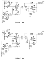
- Figure 3 is an overall schematic circuit diagram of the electronic components;
- Figure 4a is a detail schematic circuit diagram illustrating the measurement of the input signal;
- Figure 4b is a detail schematic circuit diagram illustrating the measurement of the signal from the thermopile detector;
- Figure 4c is a detail schematic circuit diagram illustrating null-offset trimming;
- Figure 4d is a detail schematic circuit diagram illustrating the measurement of the resistance of the thermopile detector;
- Figure 4e is a detail schematic circuit diagram illustrating the measurement of ambient temperature;
- Figure 5 is a detail section view corresponding to the upper portion of Figure 1c, illustrating an alternative fiber optic arrangement; and
- Figure 6 is an enlarged view of the central area of the output display of Figure 1b.
- Referring now to Figures 1a and 1b, there are seen front and side elevation views of an ear thermometer according to this invention. A
housing 10 contains the electronic and other components and bears aprobe 12 and atemperature readout display 14.Display 14 is typically a conventional liquid crystal display. The temperature is displayed in relatively large characters on either the celsius or fahrenheit scales.Display 14 also typically shows the mode, typically oral, rectal, tympanic or scan, "ready" to indicate that the system is ready for use, "calibrate" during the (very short) system calibration cycle and power supply status (typically "recharge" when a rechargeable battery requires recharging prior to use and a bar scale indicating the extent of charge from empty to full). Thus thedisplay 14 provides system status under the direction of a microprocessor. Other system characteristics may be displayed, if desired. Alternatively, a single display line, capable of showing 8 characters, may be used to selectively or in sequence display the "ready", "calibrate", etc., displays, if desired. - While housing may have any suitable configuration, the "pistol" shape shown is preferred for ease of use. The user's hand surrounds the lower portion of
housing 10, leavingdisplay area 14 visible, and probe 12 is inserted into the ear canal. Adisposable sheath 16 shown in Figure 2 covers the end ofprobe 12 and is shaped to permit the desired insertion distance so that the end ofprobe 12 is near, but not in contact, with the tympanic membrane. - A
trigger switch 18 is pressed to begin the temperature calibration and measurement sequence. A pair of mode switches 15 and 17 that allow the operator to toggle from one mode to another are located abovedisplay 14. The central area ofdisplay 14, the area below switches 15 and 17 in Figure 1b, is shown in enlarged detail in Figure 6. When the unit is turned on the unit defaults to the "tympanic" mode. Depressing switch 17 a single time when in the tympanic mode causes the device to change to the scan mode, showing the temperature adjacent to the detector. Pressingswitch 17 twice when in the tympanic mode changes to the oral mode, while pressing switch an additional time moves to the rectal mode. The scan, oral and rectal displays are simply equivalents that one would expect to correspond to the tympanic reading obtained. These are for the convenience of clinicians who normally use the oral or rectal method of thermometry. - The mode in use is shown in
area 13 in Figure 6, as are displays indicating that the calibration sequence is in progress, that the battery is being recharged and the unit is on and "ready". While all of these indicia are shown together in Figure 6, if liquid crystal display means are used, only the active one of these display words will be shown at a time. - Pressing
switch 15 twice changes the reading from Fahrenheit to Celsius and lights the "°C" instead of the "°F" on the display as shown. To recall the last five temperature readings, switch 15 is pressed once, then switch 17 is pressed once. The last five temperature readings are stepped through by pressingswitch 15 repeatedly and displayed atarea 23. Which of the last five readings is displayed is indicated by numbers 25 (only one of which is displayed at a time). Pressingtrigger switch 18 returns to the default settings and displays the last reading taken. - The display also preferably includes a conventional bar shaped
liquid crystal display 19 connected tobattery 24 so as to indicate battery condition from fully discharged to fully charged by increasing bar length. Also, an audible alarm 21 (as seen in Figure 1b) is preferably included to signal very low battery condition with suitable conventional connections tobattery 24. - The internal structure of the ear thermometer is schematically illustrated in Figures 1c-1f. The
lower portion 20 ofhousing 12 is detachable atconnection 22 which may be any suitable arrangement, such as an overlapping friction fit, including conventional ball-and-detent means, if desired. A plurality ofstacked sheaths 16 are contained inlower portion 20 for easy removal and installation overprobe 12. After each ear temperature measurement thesheath 16 overprobe 12 is slipped off and disposed of and a new sheath fromhousing 20 is installed. - The upper portion of
housing 10 contains apower supply 24, typically a rechargeable battery havingrecharging contacts 26 accessible through a pair of openings or the like inhousing 10. Liquidcrystal display panel 14 is preferably backed with a conventional display back light 28. The space withinhousing 10 above the battery and display houses the various electronic components inspace 30. -
Probe 12 containsoptical fiber bundle 32 surrounded byinsulation 34 and adisposable sheath 16. If desired,insulation 34 may be eliminated.Thermopile detector 50 as detailed below is located at the inner end offiber optics 32. If desired,detector 50 may be located inspace 30 andoptical fibers 32 maybe be curved or bent between the end ofprobe 12 and the detector. - A
stripper collet 36 is preferably located aroundhousing 12 adjacent tosheath 16. Collet is movable a short distance towardsheath 16, to "pop" the sheath off of the housing into a disposal container without requiring the operator to touch the possibly contaminated sheath after use. Installation of anew sheath 16 will returncollet 36 to the position shown in Figure 1c. If desired, an extension may be provided above the upper end of trigger (which is hinged at the upper end as seen in Figure 1c) extending upwardly and forwardly into contact withcollet 36, to movecollet 36 forwardly, so that a sheath is pushed off everytime trigger 18 is fully pressed in. - Any suitable optical fibers may be used. Excellent results are obtained with chalcogenide glass fibers of the sort available from Infrared Fiber Systems, Inc. Fibers typically have diameters of from about 120 to 440 microns and are used in bundles encased in a plastic sheath. Since the optical fiber length in our unit is rather short, the usable infrared bandwidth should be about 2 to 12 microns. The fiber bundle may have any suitable diameter, preferably in the .090 to .115 inch range. Since the fiber bundle is thin, external ambient temperature will have little adverse effect on the fibers. If desired, a thin layer of conventional polyethylene foam insulation may be provided to further reduce any outside temperature effects.
- Because the fiber optic bundle is flexible, the thermopile may be placed in the optimum location in
housing 10, with maximum isolation from outside temperature variations, with the fiber bundle curved betweenprobe 12 and the thermopile inspace 30. - Details of the
disposable sheath 16 are provided in axial section in Figure 2. The internal configuration ofsheath 16 is configured to conform to the outer surface ofprobe 12. The length oftip portion 40 is selected to be sufficient to allow theend 42 to be inserted into the ear canal to a position adjacent to and spaced from the tympanic membrane while the generallyconical wall 44 prevents insertion so far as to allowend 42 to contact the tympanic membrane. While the bulk ofsheath 16 has sufficient thickness for ease of handling, the window atend 42 should be very thin, on the order of 0.002 to 0.004 inch thick, to avoid any significant absorption of infrared radiation passing therethrough.Sheath 16 is made from any suitable material having low infrared radiation absorption characteristics, such as polyethylene.Sheath 16 is made by injection molding using a mold that has a movable mandrel or piston adjacent to thewindow end 42. When molten plastic is injected into the mold, the piston is slightly moved away from the opposite wall of the mold in the window area, allowing the plastic to flow easily into that area. Then, prior to cooling and solidification of the plastic, the piston is moved toward the opposite mold wall, compressing and forcing plastic out of that area until thewindow end 42 has a thickness of about 0.001 to 0.002 inch. This method permits rapid production of uniformly high quality sheaths while producing an infrared transmitting window of uniform thickness and high clarity so that the maximum quantity of infrared radiation from the tympanic membrane passes to the optical fiber. - The electronic circuitry for calibrating the ear thermometer and reading tympanic temperature is schematically illustrated in Figure 3. A
thermopile detector 50, typically a model 2m Detector available from Dexter Research Center, Inc., accepts an infrared input signal from the optical fiber (not shown) withinprobe 12.Detector 50 transduces the heat signal to an electrical signal which is amplified byamplifiers amplifiers digital converter 58, typically an AD7579 from Analog Devices, Inc.Converter 58 converts the analog signal to digital code and sends it tomicroprocessor 60, typically a 65512 U5 from Oki Technology, Inc. - In accordance with installed software,
microprocessor 60 controls switches 62, 64, 66, and 68 for receiving information fromdetector 50, checks the power supply by turning onswitch 70, accepts power supply voltage viaswitch 70 andamplifier 56, receives ambient temperature information from the independent transducer orresistor 72, typically an AD590 from International Components, andamplifier 74, typically another LP324. Final information is sent to display 14. Switches 62-68 are simplified schematic parts of mode switch 69 (which includes bothswitches -
Amplifier 76, typically another LP324, splits voltage from the single power supply, typically from a rechargeable battery, to bipolar voltage, indicated as -VCC and +VCC.Voltage reference 78, typically an AD580 from International Components, provides stable voltage forconverter 58 and for temperature transduction. - In this schematic, each chip performs several functions. Typically,
amplifiers thermopile detector 50 resistance, null offsetting and amplify the signal fromresistor 72.Amplifiers - Three manually operable switches are provided to control system functions.
Trigger switch 18 resets the system and initiates another temperature reading.Mode switch 17 changes the mode from tympanic, scan, oral and rectal modes as described above.Switch 15 when open causes the display to default to a temperature reading on the Fahrenheit scale and when closed changes the display to Celsius. - The output signal from a
thermopile detector 50 depends not only on the input signal from the temperature source (here the tympanic membrane) but also on the detector's own internal temperature. Thus, room temperature fluctuations will cause drift and inaccuracy in the measurement. In the past, attempts were made to overcome this problem by placing the thermopile in a metal housing and attempting to maintain that housing at a constant temperature with a heater/cooler under control of a thermocouple in contact with the thermopile. Unfortunately, the temperature of the thermocouple does not exactly equal the temperature of the detector and this arrangement requires additional circuitry and power. Since the resistance of the detector depends on its temperature, we measure the resistance of the thermopile in the circuit of Figure 3 to determine the precise thermopile temperature, i.e., the thermopile acts as its own thermometer. This resistance is used to compensate the measured signal to obtain an accurate, drift-free reading. - In a
thermopile detector 50, the thermopile consists of many thermocouples connected together. Each thermocouple consists of a "hot" (signal) junction and a "cold" (reference) junction. The measured voltage is given by the difference between these junctions. However, the input temperature signal affects not only the hot junction of the thermopile but because of its very small size and thermoconductivity the input signal also changes the temperature of the cold junction. Different input temperatures will cause different changes in the temperature of the cold junction. In the past, a calibration source, typically a reference source or chopper controller, approximately equal to the expected temperature signal (e.g. 98°F. for a thermometer to be used with humans) was used. However, the input temperature signal can vary over a relatively large range and the calibration error will increase in proportion to the difference between the temperature of the reference and the unknown source (the patient's tympanic membrane). To overcome this problem, ourmicroprocessor 60 performs the calibration immediately after the measurement. The temperatures of the thermopile hot and cold junctions stabilize during measurement. Upon completion of the measurement, the microprocessor interrupts the incoming signal, so that the output of the thermopile should be zero. Any actual signal is a result of cold junction error and is deleted from the measured signal by the microprocessor to produce a precisely accurate temperature signal. - The system operates in several hardware modes, depending upon the positions of
switches microprocessor 60. Figures 4a through 4f illustrate these different switch arrangements and the resulting functions in simplified schematic circuit form. - Figure 4a shows the simplified circuit configuration during measurement of the input signal from
thermopile detector 50.Switches switch 66 is turned on. An analog signal corresponding to the input signal is passed to analog to digital converter 58 (not seen in Figure 4a) throughoutput 84. This analog portion of the circuit operates as a differential amplifier with gain of about 2000. - Figure 4b shows the simplified circuit configuration during another measurement of the signal from the
thermopile detector 50. However, in this case switches 62, 64, 66 and 68 are all turned off, which addsresistor 86 to the circuit so that the conditions of signal measurement have been changed. By alternately measuring the detector signal with the circuits shown in Figures 4a and 4b, better accuracy and stability are obtained. - The technique for null-offset trimming is illustrated in the simplified circuit shown in Figure 4c. Here, switches 62 and 64 are turned off and switches 66 and 68 are turned on. In this case the
thermopile detector 50 output signal (differential amplifier 58 input) is equal for both inputs fromamplifiers microprocessor 60 goes through the programmed operation sequence. - The simplified circuit shown in Figure 4d measures resistance of the
thermopile detector 50 to provide information about the actual thermopile temperature. In this case switches 62, 66 and 68 are turned off and switch 64 is turned on bymicroprocessor 60. A resistor bridge which is supplied by electric current throughresistor 92 has three known values,resistors detector 50. Because of the high system gain it is possible to determinedetector 50 temperatures on the order of 0.05°C. Thus, errors resulting from changes in thermopile temperature can be easily compensated for bymicroprocessor 60. - Figure 4e illustrates the simplified circuit configuration for measuring ambient temperature from an independent transducer. This allows the ear thermometer to be checked against industry standards over a wide range of temperatures. In this case, switches 62 and 66 are turned off and switches 64 and 68 are turned on. The temperature transducer,
resistor 72 is connected through amplifier 74 (which converts °F. to °C.) is connected to the differential amplifier input. The output will correspond to 100mv/1°C. Comparison to standard temperature sources is accomplished by a conventional calibration heater. - Figure 5 is a detail section view, corresponding to the upper portion of the embodiment shown in Figure 1c. Here,
fiber optic 32 is curved anddetector 50 is placed further back inhousing 20, partially withincontainer 30. As discussed above, with the fiber optic system of this invention it is not necessary that the light guide be absolutely straight, since our fiber optics are fully effective when curved. - While certain preferred components, materials, arrangements and configurations were detailed in the above description of preferred embodiments, those may be varied, where suitable, with similar results. Other variations, applications and ramifications of this invention will occur to those skilled in the art upon reading this disclosure. Those are intended to be included within the scope of this invention, as defined in the appended claims.
Claims (21)
- An ear thermometer for measuring body core temperature through infrared radiation from the tympanic membrane which comprises:
a probe adapted to be inserted into the ear canal;
said probe containing an infrared transmitting optical fiber assembly having a first end positioned adjacent to the tympanic membrane when said probe is located in an ear canal;
a disposable sheath surrounding the probe and isolating said probe from contact with the ear canal;
said sheath including a thin infrared transmitting window formed as part of said sheath and positioned over said first optical fiber end;
a housing adjacent to said probe and receiving the second end of said optical fiber;
a thermopile detector adjacent to said second end of said optical fiber and positioned to receive radiation emitted by said second end and for generating an electrical signal corresponding to said radiation;
electrical circuit means for calibrating said signal and compensating for ambient temperature and detector temperature fluctuations and producing an output electrical signal accurately indicative of tympanic membrane temperature; and
display means for displaying indicia representing the output signal according to a selected temperature scale. - The ear thermometer according to claim 1 wherein said optical fiber assembly comprises fibers formed from chalcogenide glasses.
- The ear thermometer according to claim 1 wherein said optical fiber assembly is flexible and is curved between said probe and said thermopile within said housing.
- The ear thermometer according to claim 1 wherein said calibration means includes means for measuring the resistance of said thermopile detector to determine the precise present temperature of said detector and means to compensate for variations in said temperature to provide an accurate, drift free, detector output voltage.
- The ear thermometer according to claim 1 wherein said calibration means includes means for calibrating said thermopile detector immediately after taking a temperature measurement to assure and accurate temperature reading.
- The ear thermometer according to claim 1 wherein said electrical circuit comprises:
said thermopile detector;
thermally stable amplifier means for amplifying the output signal from said thermopile detector;
an analog to digital converter receiving the signal from said amplifier means and producing a corresponding digital signal;
a microprocessor for receiving said signal and controlling calibrations of the system and production of an accurate signal corresponding to the temperature measured and for sending said signal to said display means; and
a plurality of switches under the control of said microprocessor capable of being operated to selectively measure an input signal, measure the signal from said thermopile detector, correct for system errors including thermodrift of the input voltage and current, errors generated by content thermopotentials and electro-magnetic fields, measure resistance of the thermopile detector and correct for thermopile temperature errors, measure ambient temperature and correct for errors caused by variations thereof, and measure voltage from the power supply and indicate sufficiency thereof. - The ear thermometer according to claim 1 wherein said display is a liquid crystal display means capable of selectively displaying temperature on celsius or fahrenheit scales, and displaying power supply status and system status.
- The ear thermometer according to claim 7 where said display means includes means for selectively displaying the tympanic temperature measured and that temperature converted to equivalent oral or rectal temperatures.
- The ear thermometer according to claim 7 wherein said display means includes bar shaped liquid crystal display means for displaying battery condition between fully discharged and fully charged in accordance with displayed bar length.
- The ear thermometer according to claim 7 wherein said display means includes audible alarm means for indicating low battery charge conditions.
- The ear thermometer according to claim 1 further including a slidable collet means in contact with an in place sheath and means for moving said collet toward said sheath to eject said sheath without requiring an operator to touch said sheath.
- An ear thermometer for measuring body core temperature through infrared radiation from the tympanic membrane which comprises:
a probe adapted to be inserted into the ear canal;
said probe containing an infrared transmitting optical fiber assembly having a first end positioned adjacent to the tympanic membrane when said probe is located in an ear canal;
a disposable sheath surrounding the probe and isolating said probe from contact with the ear canal;
said sheath including a thin infrared transmitting window formed as part of said sheath and positioned over said first optical fiber end;
a housing adjacent to said probe and receiving the second end of said optical fiber;
a thermopile detector adjacent to said second end of said optical fiber and positioned to receive radiation emitted by said second end and for generating an electrical signal corresponding to said radiation;
thermally stable amplifier means for amplifying the output signal from said thermopile detector;
an analog to digital converter receiving the signal from said amplifier means and producing a corresponding digital signal;
a microprocessor for receiving said signal and controlling calibrations of the system and production of an accurate signal corresponding to the temperature measured and for sending said signal to said display means; and
a plurality of switches under the control of said microprocessor capable of being operated to selectively measure an input signal, measure the signal from said thermopile detector, correct for system errors including thermodrift of the input voltage and current, errors generated by content thermopotentials and electro-magnetic fields, measure resistance of the thermopile detector and correct for thermopile temperature errors, measure ambient temperature and correct for errors caused by variations thereof, and measure voltage from the power supply and indicate sufficiency thereof: and
display means for displaying indicia representing the output signal according to a selected temperature scale. - The ear thermometer according to claim 12 further including electrical circuit means for calibrating said signal and compensating for ambient temperature and detector temperature fluctuations and producing an output electrical signal accurately indicative of tympanic membrane temperature;
- The ear thermometer according to claim 13 wherein said calibration means includes means for measuring the resistance of said thermopile detector to determine the precise present temperature of said detector and means to compensate for variations in said temperature to provide an accurate, drift free, detector output voltage.
- The ear thermometer according to claim 12 wherein said optical fiber assembly comprises fibers formed from chalcogenide glasses.
- The ear thermometer according to claim 12 wherein said optical fiber assembly is flexible and is curved between said probe and said thermopile within said housing.
- The ear thermometer according to claim 12 wherein said display is a liquid crystal display means capable of selectively displaying temperature on celsius or fahrenheit scales, and displaying power supply status and system status.
- The ear thermometer according to claim 17 where said display means includes means for selectively displaying the tympanic temperature measured and that temperature converted to equivalent oral or rectal temperatures.
- The ear thermometer according to claim 17 wherein said display means includes bar shaped liquid crystal display means for displaying battery condition between fully discharged and fully charged in accordance with displayed bar length.
- The ear thermometer according to claim 17 wherein said display means includes audible alarm means for indicating low battery charge conditions.
- The ear thermometer according to claim 12 further including a slidable collet means in contact with an in place sheath and means for moving said collet toward said sheath to eject said sheath without requiring an operator to touch said sheath.
Applications Claiming Priority (2)
| Application Number | Priority Date | Filing Date | Title |
|---|---|---|---|
| US07/664,294 US5167235A (en) | 1991-03-04 | 1991-03-04 | Fiber optic ear thermometer |
| US664294 | 2000-09-18 |
Publications (2)
| Publication Number | Publication Date |
|---|---|
| EP0502277A2 true EP0502277A2 (en) | 1992-09-09 |
| EP0502277A3 EP0502277A3 (en) | 1993-06-09 |
Family
ID=24665422
Family Applications (1)
| Application Number | Title | Priority Date | Filing Date |
|---|---|---|---|
| EP19910310451 Withdrawn EP0502277A3 (en) | 1991-03-04 | 1991-11-13 | Fiber optic ear thermometer |
Country Status (3)
| Country | Link |
|---|---|
| US (1) | US5167235A (en) |
| EP (1) | EP0502277A3 (en) |
| JP (1) | JPH06154173A (en) |
Cited By (6)
| Publication number | Priority date | Publication date | Assignee | Title |
|---|---|---|---|---|
| WO1997019331A1 (en) * | 1995-11-18 | 1997-05-29 | Braun Aktiengesellschaft | Process for evaluating the signal of an infrared thermometer, and infrared thermometer |
| WO1997019332A1 (en) * | 1995-11-18 | 1997-05-29 | Braun Aktiengesellschaft | Infrared radiation thermometer |
| DE19724054A1 (en) * | 1997-06-07 | 1998-12-10 | Braun Ag | Radiation thermometer and protective cap therefor |
| EP1077046A1 (en) * | 1998-05-06 | 2001-02-21 | Matsushita Electric Industrial Co., Ltd. | Ear type thermometer for women |
| EP1190668A1 (en) * | 1999-06-11 | 2002-03-27 | Omron Corporation | Ear type clinical thermometer |
| EP1519172A1 (en) * | 2003-09-26 | 2005-03-30 | ARTSANA S.p.A. | Method for measuring the temperature of the human body by an infrared thermometer and a thermometer for implementing the method |
Families Citing this family (129)
| Publication number | Priority date | Publication date | Assignee | Title |
|---|---|---|---|---|
| US5179936A (en) * | 1984-10-23 | 1993-01-19 | Intelligent Medical Systems, Inc. | Disposable speculum with membrane bonding ring |
| US5653238A (en) * | 1988-12-06 | 1997-08-05 | Exergen Corporation | Radiation detector probe |
| EP0445783B1 (en) * | 1990-03-08 | 1996-02-07 | Ivac Corporation | Thermally isolated probe |
| US5419311A (en) * | 1993-02-18 | 1995-05-30 | Olympus Optical Co., Ltd. | Endoscope apparatus of a type having cover for covering the endoscope |
| US5368038A (en) * | 1993-03-08 | 1994-11-29 | Thermoscan Inc. | Optical system for an infrared thermometer |
| JP3184659B2 (en) * | 1993-04-01 | 2001-07-09 | テルモ株式会社 | Thermometer |
| US5479931A (en) * | 1993-11-18 | 1996-01-02 | Thermoscan, Inc. | IR thermometer |
| JPH0856908A (en) * | 1994-08-19 | 1996-03-05 | Terumo Corp | Eardrum thermometer |
| US5626139A (en) * | 1994-09-23 | 1997-05-06 | Artech Industries, Inc. | Tympanic thermometer |
| US5725308A (en) * | 1994-12-23 | 1998-03-10 | Rtd Technology, Inc. | Quick registering thermometer |
| US5673692A (en) * | 1995-02-03 | 1997-10-07 | Biosignals Ltd. Co. | Single site, multi-variable patient monitor |
| USD378282S (en) * | 1995-07-31 | 1997-03-04 | Braun Aktiengesellschaft | Thermometer |
| US5820264A (en) * | 1996-03-25 | 1998-10-13 | Oriental System Technology, Inc. | Tympanic thermometer arrangement |
| USD388343S (en) * | 1996-04-22 | 1997-12-30 | Omron Corporation | Ear-inserted-type clinical thermometer |
| IL118050A (en) | 1996-04-26 | 2000-07-26 | Katzir Avraham | Infrared-transmitting-fiber-optic-cable-based device for non-contact thermometry |
| US5666956A (en) * | 1996-05-20 | 1997-09-16 | Buchert; Janusz Michal | Instrument and method for non-invasive monitoring of human tissue analyte by measuring the body's infrared radiation |
| US6689091B2 (en) | 1996-08-02 | 2004-02-10 | Tuan Bui | Medical apparatus with remote control |
| US5895371A (en) * | 1996-08-27 | 1999-04-20 | Sabratek Corporation | Medical treatment apparatus and method |
| US6605057B2 (en) | 1996-10-24 | 2003-08-12 | Medtronic Ave, Inc. | Reinforced monorail balloon catheter |
| US5833367A (en) | 1996-11-12 | 1998-11-10 | Trutek, Inc. | Tympanic thermometer probe cover |
| US6030117A (en) | 1996-11-12 | 2000-02-29 | Trutek, Inc. | Tympanic thermometer probe cover |
| US5790040A (en) * | 1996-12-13 | 1998-08-04 | Interactive Technologies, Inc. | Battery-operated security system sensors |
| AU7807898A (en) | 1997-06-03 | 1998-12-21 | Trutek, Inc. | Tympanic thermometer with modular sensing probe |
| US6056435A (en) | 1997-06-24 | 2000-05-02 | Exergen Corporation | Ambient and perfusion normalized temperature detector |
| TW389837B (en) * | 1997-07-16 | 2000-05-11 | Terumo Corp | Ear type clinical thermometer |
| US5991700A (en) * | 1997-10-15 | 1999-11-23 | Sherwood Services, A.G. | EMI stability indicator for tympanic thermometer |
| WO1999057528A1 (en) | 1998-05-02 | 1999-11-11 | Focal, Inc. | Light source power tester |
| US5967992A (en) | 1998-06-03 | 1999-10-19 | Trutex, Inc. | Radiometric temperature measurement based on empirical measurements and linear functions |
| US6292685B1 (en) | 1998-09-11 | 2001-09-18 | Exergen Corporation | Temporal artery temperature detector |
| IL126224A0 (en) | 1998-09-15 | 1999-05-09 | Gerlitz Jonathan | Ear thermometer and detector therefor |
| US6398727B1 (en) * | 1998-12-23 | 2002-06-04 | Baxter International Inc. | Method and apparatus for providing patient care |
| US6231560B1 (en) * | 1999-02-10 | 2001-05-15 | Baxter International Inc | Method and apparatus for automatically controlling the level of medication |
| US6123454A (en) | 1999-06-11 | 2000-09-26 | Trutek, Inc. | Tympanic thermometer disposable probe cover with further stretching prevention structure |
| US6450970B1 (en) * | 1999-11-16 | 2002-09-17 | Ron Mahler | Method and device for diagnosing an inflammatory process |
| DE19954756A1 (en) * | 1999-11-17 | 2001-05-31 | Odim Gmbh | Device and method for examining biological tissue |
| US6319206B1 (en) * | 1999-11-24 | 2001-11-20 | Exergen Corporation | Temporal thermometer disposable cap |
| US6425688B1 (en) * | 2000-04-21 | 2002-07-30 | Actherm Inc. | Infrared temperature wave guide device |
| JP3945189B2 (en) * | 2001-06-01 | 2007-07-18 | オムロンヘルスケア株式会社 | Infrared thermometer |
| US20030125662A1 (en) | 2002-01-03 | 2003-07-03 | Tuan Bui | Method and apparatus for providing medical treatment therapy based on calculated demand |
| US8775196B2 (en) | 2002-01-29 | 2014-07-08 | Baxter International Inc. | System and method for notification and escalation of medical data |
| US10173008B2 (en) | 2002-01-29 | 2019-01-08 | Baxter International Inc. | System and method for communicating with a dialysis machine through a network |
| US8234128B2 (en) | 2002-04-30 | 2012-07-31 | Baxter International, Inc. | System and method for verifying medical device operational parameters |
| US6980708B2 (en) * | 2002-05-13 | 2005-12-27 | Bartec Gmbh | Device for fibre optic temperature measurement with an optical fibre |
| US6850789B2 (en) * | 2002-07-29 | 2005-02-01 | Welch Allyn, Inc. | Combination SPO2/temperature measuring apparatus |
| US6968222B2 (en) | 2003-05-02 | 2005-11-22 | Oculir, Inc. | Methods and device for non-invasive analyte measurement |
| US6958039B2 (en) | 2003-05-02 | 2005-10-25 | Oculir, Inc. | Method and instruments for non-invasive analyte measurement |
| US6975892B2 (en) | 2003-10-21 | 2005-12-13 | Oculir, Inc. | Methods for non-invasive analyte measurement from the conjunctiva |
| US7107088B2 (en) * | 2003-08-25 | 2006-09-12 | Sarnoff Corporation | Pulse oximetry methods and apparatus for use within an auditory canal |
| US20050059870A1 (en) * | 2003-08-25 | 2005-03-17 | Aceti John Gregory | Processing methods and apparatus for monitoring physiological parameters using physiological characteristics present within an auditory canal |
| US20050083991A1 (en) * | 2003-10-17 | 2005-04-21 | Anthony Wong | Probe cover storage system for ear thermometer |
| US20050085733A1 (en) * | 2003-10-17 | 2005-04-21 | Anthony Wong | Ear thermometer illumination system |
| EP1530034A1 (en) * | 2003-11-05 | 2005-05-11 | Microlife Intellectual Property GmbH | An infrared thermometer and a method for determining a temperature |
| US8295523B2 (en) | 2007-10-04 | 2012-10-23 | SoundBeam LLC | Energy delivery and microphone placement methods for improved comfort in an open canal hearing aid |
| US7668325B2 (en) | 2005-05-03 | 2010-02-23 | Earlens Corporation | Hearing system having an open chamber for housing components and reducing the occlusion effect |
| US7867160B2 (en) | 2004-10-12 | 2011-01-11 | Earlens Corporation | Systems and methods for photo-mechanical hearing transduction |
| US7955249B2 (en) * | 2005-10-31 | 2011-06-07 | Earlens Corporation | Output transducers for hearing systems |
| TWM270787U (en) * | 2004-08-02 | 2005-07-21 | Mesure Technology Co Ltd | Ear temperature detector |
| WO2006017746A2 (en) * | 2004-08-06 | 2006-02-16 | Heller Adam Ph D | Devices and methods of screening for neoplastic and inflammatory disease |
| TWI273224B (en) * | 2005-02-12 | 2007-02-11 | Radiant Innovation Inc | Protective cover structure of an ear thermometer |
| US9037247B2 (en) | 2005-11-10 | 2015-05-19 | ElectroCore, LLC | Non-invasive treatment of bronchial constriction |
| TW200800098A (en) * | 2006-06-16 | 2008-01-01 | Radiant Innovation Inc | Infrared clinical thermometer |
| US20080125749A1 (en) * | 2006-08-29 | 2008-05-29 | Boston Scientific Scimed, Inc. | Self-powered medical devices |
| TW200841859A (en) * | 2007-04-27 | 2008-11-01 | Actherm Inc | Infrared thermometer |
| US8100886B2 (en) * | 2007-08-15 | 2012-01-24 | Visiomed Group Sa | Aspirator assembly |
| US20090076441A1 (en) * | 2007-08-15 | 2009-03-19 | Eric Sebban | Aspirator assembly |
| US20090074027A1 (en) * | 2007-09-18 | 2009-03-19 | Vatell Corporation | Heat flux sensor incorporating light conveyance |
| WO2009049320A1 (en) | 2007-10-12 | 2009-04-16 | Earlens Corporation | Multifunction system and method for integrated hearing and communiction with noise cancellation and feedback management |
| US20090125330A1 (en) * | 2007-11-09 | 2009-05-14 | Eric Sebban | Non-invasive medical data collecting assembly |
| DK2301262T3 (en) | 2008-06-17 | 2017-11-13 | Earlens Corp | Optical electromechanical hearing aids with combined power and signal structure |
| US8396239B2 (en) | 2008-06-17 | 2013-03-12 | Earlens Corporation | Optical electro-mechanical hearing devices with combined power and signal architectures |
| BRPI0915203A2 (en) | 2008-06-17 | 2016-02-16 | Earlens Corp | device, system and method for transmitting an audio signal, and device and method for stimulating a target tissue |
| US8057679B2 (en) | 2008-07-09 | 2011-11-15 | Baxter International Inc. | Dialysis system having trending and alert generation |
| US10089443B2 (en) | 2012-05-15 | 2018-10-02 | Baxter International Inc. | Home medical device systems and methods for therapy prescription and tracking, servicing and inventory |
| US20100046579A1 (en) * | 2008-08-21 | 2010-02-25 | Jeff Baker | Rechargeable Ear Thermometer |
| KR20110086804A (en) | 2008-09-22 | 2011-08-01 | 사운드빔, 엘엘씨 | Balanced armature devices and methods for hearing |
| US8554579B2 (en) | 2008-10-13 | 2013-10-08 | Fht, Inc. | Management, reporting and benchmarking of medication preparation |
| US8186876B2 (en) * | 2009-04-20 | 2012-05-29 | Welch Allyn, Inc. | Calibrated assembly for IR thermometer apparatus |
| CN102598712A (en) | 2009-06-05 | 2012-07-18 | 音束有限责任公司 | Optically coupled acoustic middle ear implant systems and methods |
| US9544700B2 (en) | 2009-06-15 | 2017-01-10 | Earlens Corporation | Optically coupled active ossicular replacement prosthesis |
| CN102598713A (en) | 2009-06-18 | 2012-07-18 | 音束有限责任公司 | Eardrum implantable devices for hearing systems and methods |
| EP2443773B1 (en) | 2009-06-18 | 2017-01-11 | Earlens Corporation | Optically coupled cochlear implant systems |
| BRPI1016075A2 (en) | 2009-06-22 | 2016-05-10 | SoundBeam LLC | device for transmitting sound to a user's ear and associated methods. |
| EP2446645B1 (en) | 2009-06-22 | 2020-05-06 | Earlens Corporation | Optically coupled bone conduction systems and methods |
| WO2010151647A2 (en) | 2009-06-24 | 2010-12-29 | SoundBeam LLC | Optically coupled cochlear actuator systems and methods |
| WO2010151636A2 (en) | 2009-06-24 | 2010-12-29 | SoundBeam LLC | Optical cochlear stimulation devices and methods |
| US20120083710A1 (en) | 2010-09-30 | 2012-04-05 | Medism Ltd. | Ergonomic hand-held thermometer |
| EP2656639B1 (en) | 2010-12-20 | 2020-05-13 | Earlens Corporation | Anatomically customized ear canal hearing apparatus |
| US8353870B2 (en) | 2011-04-26 | 2013-01-15 | Fresenius Medical Care Holdings, Inc. | Medical temperature sensors and related systems and methods |
| US8292500B1 (en) | 2011-09-30 | 2012-10-23 | Tyco Healthcare Group Lp | IR sensor for electronic thermometer |
| US8949065B2 (en) | 2011-09-30 | 2015-02-03 | Covidien Lp | Capacitive sensor for thermometer probe |
| US10552577B2 (en) | 2012-08-31 | 2020-02-04 | Baxter Corporation Englewood | Medication requisition fulfillment system and method |
| US9872812B2 (en) | 2012-09-28 | 2018-01-23 | Kpr U.S., Llc | Residual pressure control in a compression device |
| SG11201503190RA (en) | 2012-10-26 | 2015-05-28 | Baxter Corp Englewood | Improved image acquisition for medical dose preparation system |
| EP2911641B1 (en) | 2012-10-26 | 2018-10-17 | Baxter Corporation Englewood | Improved work station for medical dose preparation system |
| US10034103B2 (en) | 2014-03-18 | 2018-07-24 | Earlens Corporation | High fidelity and reduced feedback contact hearing apparatus and methods |
| EP3161778A4 (en) | 2014-06-30 | 2018-03-14 | Baxter Corporation Englewood | Managed medical information exchange |
| EP3169396B1 (en) | 2014-07-14 | 2021-04-21 | Earlens Corporation | Sliding bias and peak limiting for optical hearing devices |
| US11107574B2 (en) | 2014-09-30 | 2021-08-31 | Baxter Corporation Englewood | Management of medication preparation with formulary management |
| US11575673B2 (en) | 2014-09-30 | 2023-02-07 | Baxter Corporation Englewood | Central user management in a distributed healthcare information management system |
| US9571913B2 (en) | 2014-10-30 | 2017-02-14 | Smartear, Inc. | Smart flexible interactive earplug |
| US9924276B2 (en) | 2014-11-26 | 2018-03-20 | Earlens Corporation | Adjustable venting for hearing instruments |
| WO2016090091A1 (en) | 2014-12-05 | 2016-06-09 | Baxter Corporation Englewood | Dose preparation data analytics |
| EP3265989A4 (en) | 2015-03-03 | 2018-10-24 | Baxter Corporation Englewood | Pharmacy workflow management with integrated alerts |
| CA2985719C (en) | 2015-06-25 | 2024-03-26 | Gambro Lundia Ab | Medical device system and method having a distributed database |
| DK3355801T3 (en) | 2015-10-02 | 2021-06-21 | Earlens Corp | Adapted ear canal device for drug delivery |
| US11350226B2 (en) | 2015-12-30 | 2022-05-31 | Earlens Corporation | Charging protocol for rechargeable hearing systems |
| US10492010B2 (en) | 2015-12-30 | 2019-11-26 | Earlens Corporations | Damping in contact hearing systems |
| US10178483B2 (en) | 2015-12-30 | 2019-01-08 | Earlens Corporation | Light based hearing systems, apparatus, and methods |
| USD798843S1 (en) | 2016-01-19 | 2017-10-03 | Smartear, Inc. | In-ear utility device |
| USD794611S1 (en) * | 2016-01-19 | 2017-08-15 | Smartear, Inc. | In-ear utility device |
| US10309835B2 (en) * | 2016-01-21 | 2019-06-04 | Honeywell International Inc. | Body core temperature measurement |
| USD795224S1 (en) * | 2016-03-08 | 2017-08-22 | Smartear, Inc. | In-ear utility device |
| US9838771B1 (en) | 2016-05-25 | 2017-12-05 | Smartear, Inc. | In-ear utility device having a humidity sensor |
| US20170347177A1 (en) | 2016-05-25 | 2017-11-30 | Smartear, Inc. | In-Ear Utility Device Having Sensors |
| US10045130B2 (en) | 2016-05-25 | 2018-08-07 | Smartear, Inc. | In-ear utility device having voice recognition |
| CN109952771A (en) | 2016-09-09 | 2019-06-28 | 伊尔兰斯公司 | Contact hearing system, device and method |
| WO2018093733A1 (en) | 2016-11-15 | 2018-05-24 | Earlens Corporation | Improved impression procedure |
| WO2018114346A1 (en) | 2016-12-21 | 2018-06-28 | Gambro Lundia Ab | Medical device system including information technology infrastructure having secure cluster domain supporting external domain |
| US10410634B2 (en) | 2017-05-18 | 2019-09-10 | Smartear, Inc. | Ear-borne audio device conversation recording and compressed data transmission |
| USD883491S1 (en) | 2017-09-30 | 2020-05-05 | Smartear, Inc. | In-ear device |
| US10582285B2 (en) | 2017-09-30 | 2020-03-03 | Smartear, Inc. | Comfort tip with pressure relief valves and horn |
| JP6999385B2 (en) * | 2017-11-30 | 2022-01-18 | 株式会社テクノ・コモンズ | Object data measuring device |
| WO2019173470A1 (en) | 2018-03-07 | 2019-09-12 | Earlens Corporation | Contact hearing device and retention structure materials |
| WO2019199680A1 (en) | 2018-04-09 | 2019-10-17 | Earlens Corporation | Dynamic filter |
| USD883470S1 (en) * | 2019-10-23 | 2020-05-05 | Junjie Wei | Nasal aspirator |
| CN115485533A (en) * | 2020-06-10 | 2022-12-16 | 松下知识产权经营株式会社 | Control method of thermal imaging camera and control device of thermal imaging camera |
| USD919459S1 (en) * | 2020-09-15 | 2021-05-18 | Zhanjiang Quanben Trading Co., Ltd. | Thermometer |
| USD1013151S1 (en) * | 2022-05-17 | 2024-01-30 | Hetaida Technology Co., Ltd. | Electric nasal aspirator |
| USD1017796S1 (en) * | 2022-09-07 | 2024-03-12 | Ling Pan | Electric nasal aspirator |
Citations (6)
| Publication number | Priority date | Publication date | Assignee | Title |
|---|---|---|---|---|
| JPS60195029A (en) * | 1984-03-19 | 1985-10-03 | Hitachi Ltd | Preparation of optical fiber for transmitting infrared ray |
| JPS61138130A (en) * | 1984-12-10 | 1986-06-25 | Matsushita Electric Works Ltd | Clinical thermometer |
| WO1990002521A1 (en) * | 1988-09-15 | 1990-03-22 | Temp-Stik Corporation | Infrared clinical thermometer |
| WO1990006090A1 (en) * | 1988-12-06 | 1990-06-14 | Exergen Corporation | Radiation detector suitable for tympanic temperature measurement |
| EP0411121A1 (en) * | 1987-12-25 | 1991-02-06 | Nippon Steel Corporation | Optical thermometer |
| US4993424A (en) * | 1989-12-04 | 1991-02-19 | Diatek, Incorporated | Infrared medical thermometer |
Family Cites Families (12)
| Publication number | Priority date | Publication date | Assignee | Title |
|---|---|---|---|---|
| US3779233A (en) * | 1971-09-30 | 1973-12-18 | Espey Mfg & Electronics Corp | Speculum instrument with disposable forward section |
| US3878836A (en) * | 1973-08-23 | 1975-04-22 | Products Int Marketing | Disposable speculum for tympanic thermometer |
| US4662360A (en) * | 1984-10-23 | 1987-05-05 | Intelligent Medical Systems, Inc. | Disposable speculum |
| US4602642A (en) * | 1984-10-23 | 1986-07-29 | Intelligent Medical Systems, Inc. | Method and apparatus for measuring internal body temperature utilizing infrared emissions |
| US4583526A (en) * | 1985-01-14 | 1986-04-22 | Ali Mir A | Flexible endoscope structure |
| US4784149A (en) * | 1986-01-13 | 1988-11-15 | Optical Sensors, Inc. | Infrared thermometer with automatic calibration |
| US4679556A (en) * | 1986-04-16 | 1987-07-14 | Shiley Inc. | Releasable holder and method of use |
| US4800886A (en) * | 1986-07-14 | 1989-01-31 | C. R. Bard, Inc. | Sensor for measuring the concentration of a gaseous component in a fluid by absorption |
| JP2826337B2 (en) * | 1988-04-12 | 1998-11-18 | シチズン時計株式会社 | Radiation thermometer |
| US5012813A (en) * | 1988-12-06 | 1991-05-07 | Exergen Corporation | Radiation detector having improved accuracy |
| US4900162A (en) * | 1989-03-20 | 1990-02-13 | Ivac Corporation | Infrared thermometry system and method |
| US4986671A (en) * | 1989-04-12 | 1991-01-22 | Luxtron Corporation | Three-parameter optical fiber sensor and system |
-
1991
- 1991-03-04 US US07/664,294 patent/US5167235A/en not_active Expired - Fee Related
- 1991-11-13 EP EP19910310451 patent/EP0502277A3/en not_active Withdrawn
-
1992
- 1992-01-29 JP JP4038546A patent/JPH06154173A/en active Pending
Patent Citations (6)
| Publication number | Priority date | Publication date | Assignee | Title |
|---|---|---|---|---|
| JPS60195029A (en) * | 1984-03-19 | 1985-10-03 | Hitachi Ltd | Preparation of optical fiber for transmitting infrared ray |
| JPS61138130A (en) * | 1984-12-10 | 1986-06-25 | Matsushita Electric Works Ltd | Clinical thermometer |
| EP0411121A1 (en) * | 1987-12-25 | 1991-02-06 | Nippon Steel Corporation | Optical thermometer |
| WO1990002521A1 (en) * | 1988-09-15 | 1990-03-22 | Temp-Stik Corporation | Infrared clinical thermometer |
| WO1990006090A1 (en) * | 1988-12-06 | 1990-06-14 | Exergen Corporation | Radiation detector suitable for tympanic temperature measurement |
| US4993424A (en) * | 1989-12-04 | 1991-02-19 | Diatek, Incorporated | Infrared medical thermometer |
Non-Patent Citations (2)
| Title |
|---|
| PATENT ABSTRACTS OF JAPAN vol. 010, no. 049 (C-330)26 February 1986 & JP-A-60 195 029 ( HITACHI SEISAKUSHO ) * |
| PATENT ABSTRACTS OF JAPAN vol. 010, no. 334 (P-515)13 November 1986 & JP-A-61 138 130 ( MATSUSHITA ELECTRIC WORKS ) 25 June 1986 * |
Cited By (17)
| Publication number | Priority date | Publication date | Assignee | Title |
|---|---|---|---|---|
| WO1997019332A1 (en) * | 1995-11-18 | 1997-05-29 | Braun Aktiengesellschaft | Infrared radiation thermometer |
| US6149297A (en) * | 1995-11-18 | 2000-11-21 | Braun Gmbh | Infrared radiation thermometer |
| WO1997019331A1 (en) * | 1995-11-18 | 1997-05-29 | Braun Aktiengesellschaft | Process for evaluating the signal of an infrared thermometer, and infrared thermometer |
| US6195581B1 (en) | 1995-11-18 | 2001-02-27 | Braun Gmbh | Process for evaluating the signal of an infrared thermometer, and infrared thermometer |
| DE19724054C2 (en) * | 1997-06-07 | 2002-09-12 | Braun Gmbh | Radiation thermometer and protective cap therefor |
| DE19724054A1 (en) * | 1997-06-07 | 1998-12-10 | Braun Ag | Radiation thermometer and protective cap therefor |
| WO1998057134A1 (en) * | 1997-06-07 | 1998-12-17 | Braun Gmbh | Radiation thermometer and protective cap |
| US6097979A (en) * | 1997-06-07 | 2000-08-01 | Braun Gmbh | Radiation thermometer and protective cover therefor |
| US6522912B1 (en) | 1998-05-06 | 2003-02-18 | Matsushita Electric Industrial Co., Ltd. | Ear type thermometer |
| EP1077046A4 (en) * | 1998-05-06 | 2002-05-29 | Matsushita Electric Ind Co Ltd | Ear type thermometer for women |
| EP1077046A1 (en) * | 1998-05-06 | 2001-02-21 | Matsushita Electric Industrial Co., Ltd. | Ear type thermometer for women |
| EP1190668A1 (en) * | 1999-06-11 | 2002-03-27 | Omron Corporation | Ear type clinical thermometer |
| EP1190668A4 (en) * | 1999-06-11 | 2003-02-05 | Omron Tateisi Electronics Co | Ear type clinical thermometer |
| EP1454583A2 (en) * | 1999-06-11 | 2004-09-08 | Omron Corporation | Ear type clinical thermometer |
| EP1454583A3 (en) * | 1999-06-11 | 2004-11-17 | Omron Corporation | Ear type clinical thermometer |
| US7063458B1 (en) | 1999-06-11 | 2006-06-20 | Omron Corporation | Ear type clinical thermometer |
| EP1519172A1 (en) * | 2003-09-26 | 2005-03-30 | ARTSANA S.p.A. | Method for measuring the temperature of the human body by an infrared thermometer and a thermometer for implementing the method |
Also Published As
| Publication number | Publication date |
|---|---|
| JPH06154173A (en) | 1994-06-03 |
| US5167235A (en) | 1992-12-01 |
| EP0502277A3 (en) | 1993-06-09 |
Similar Documents
| Publication | Publication Date | Title |
|---|---|---|
| US5167235A (en) | Fiber optic ear thermometer | |
| JP2704672B2 (en) | Infrared thermometer using calibration mapping | |
| US4895164A (en) | Infrared clinical thermometer | |
| EP0871023B1 (en) | Infrared thermometer | |
| US4784149A (en) | Infrared thermometer with automatic calibration | |
| US4790324A (en) | Method and apparatus for measuring internal body temperature utilizing infrared emissions | |
| US4602642A (en) | Method and apparatus for measuring internal body temperature utilizing infrared emissions | |
| US5626139A (en) | Tympanic thermometer | |
| US8123401B2 (en) | Probe cover having a blackbody | |
| US5368038A (en) | Optical system for an infrared thermometer | |
| EP0411121A1 (en) | Optical thermometer | |
| WO1996008994A9 (en) | Tympanic thermometer | |
| JPH04504367A (en) | ear temperature detection device | |
| US20050207470A1 (en) | Focusing thermometer | |
| JPH039724A (en) | Body temperature measuring apparatus |
Legal Events
| Date | Code | Title | Description |
|---|---|---|---|
| PUAI | Public reference made under article 153(3) epc to a published international application that has entered the european phase |
Free format text: ORIGINAL CODE: 0009012 |
|
| AK | Designated contracting states |
Kind code of ref document: A2 Designated state(s): AT BE CH DE DK ES FR GB GR IT LI LU NL SE |
|
| PUAL | Search report despatched |
Free format text: ORIGINAL CODE: 0009013 |
|
| AK | Designated contracting states |
Kind code of ref document: A3 Designated state(s): AT BE CH DE DK ES FR GB GR IT LI LU NL SE |
|
| STAA | Information on the status of an ep patent application or granted ep patent |
Free format text: STATUS: THE APPLICATION IS DEEMED TO BE WITHDRAWN |
|
| 18D | Application deemed to be withdrawn |
Effective date: 19931210 |