EP0502822B1 - Vorrichtung zum Verschieben und Schwenken eines Behälter-Verschlusses - Google Patents
Vorrichtung zum Verschieben und Schwenken eines Behälter-Verschlusses Download PDFInfo
- Publication number
- EP0502822B1 EP0502822B1 EP92810144A EP92810144A EP0502822B1 EP 0502822 B1 EP0502822 B1 EP 0502822B1 EP 92810144 A EP92810144 A EP 92810144A EP 92810144 A EP92810144 A EP 92810144A EP 0502822 B1 EP0502822 B1 EP 0502822B1
- Authority
- EP
- European Patent Office
- Prior art keywords
- container
- sliding
- container closure
- closure
- cover
- Prior art date
- Legal status (The legal status is an assumption and is not a legal conclusion. Google has not performed a legal analysis and makes no representation as to the accuracy of the status listed.)
- Expired - Lifetime
Links
Images


Classifications
-
- B—PERFORMING OPERATIONS; TRANSPORTING
- B65—CONVEYING; PACKING; STORING; HANDLING THIN OR FILAMENTARY MATERIAL
- B65D—CONTAINERS FOR STORAGE OR TRANSPORT OF ARTICLES OR MATERIALS, e.g. BAGS, BARRELS, BOTTLES, BOXES, CANS, CARTONS, CRATES, DRUMS, JARS, TANKS, HOPPERS, FORWARDING CONTAINERS; ACCESSORIES, CLOSURES, OR FITTINGS THEREFOR; PACKAGING ELEMENTS; PACKAGES
- B65D90/00—Component parts, details or accessories for large containers
- B65D90/008—Doors for containers, e.g. ISO-containers
-
- B—PERFORMING OPERATIONS; TRANSPORTING
- B65—CONVEYING; PACKING; STORING; HANDLING THIN OR FILAMENTARY MATERIAL
- B65D—CONTAINERS FOR STORAGE OR TRANSPORT OF ARTICLES OR MATERIALS, e.g. BAGS, BARRELS, BOTTLES, BOXES, CANS, CARTONS, CRATES, DRUMS, JARS, TANKS, HOPPERS, FORWARDING CONTAINERS; ACCESSORIES, CLOSURES, OR FITTINGS THEREFOR; PACKAGING ELEMENTS; PACKAGES
- B65D90/00—Component parts, details or accessories for large containers
- B65D90/54—Gates or closures
- B65D90/62—Gates or closures having closure members movable out of the plane of the opening
- B65D90/623—Gates or closures having closure members movable out of the plane of the opening having a rotational motion
-
- B—PERFORMING OPERATIONS; TRANSPORTING
- B65—CONVEYING; PACKING; STORING; HANDLING THIN OR FILAMENTARY MATERIAL
- B65D—CONTAINERS FOR STORAGE OR TRANSPORT OF ARTICLES OR MATERIALS, e.g. BAGS, BARRELS, BOTTLES, BOXES, CANS, CARTONS, CRATES, DRUMS, JARS, TANKS, HOPPERS, FORWARDING CONTAINERS; ACCESSORIES, CLOSURES, OR FITTINGS THEREFOR; PACKAGING ELEMENTS; PACKAGES
- B65D90/00—Component parts, details or accessories for large containers
- B65D90/54—Gates or closures
- B65D90/62—Gates or closures having closure members movable out of the plane of the opening
- B65D90/626—Gates or closures having closure members movable out of the plane of the opening having a linear motion
-
- B—PERFORMING OPERATIONS; TRANSPORTING
- B65—CONVEYING; PACKING; STORING; HANDLING THIN OR FILAMENTARY MATERIAL
- B65D—CONTAINERS FOR STORAGE OR TRANSPORT OF ARTICLES OR MATERIALS, e.g. BAGS, BARRELS, BOTTLES, BOXES, CANS, CARTONS, CRATES, DRUMS, JARS, TANKS, HOPPERS, FORWARDING CONTAINERS; ACCESSORIES, CLOSURES, OR FITTINGS THEREFOR; PACKAGING ELEMENTS; PACKAGES
- B65D2590/00—Component parts, details or accessories for large containers
- B65D2590/54—Gates or closures
- B65D2590/66—Operating devices therefor
- B65D2590/662—Operating devices therefor allowing a particular motion, e.g. combination of rotational and linear
Definitions
- the invention relates to a device for moving and pivoting a lid-shaped closure on a container, wherein the container closure is provided with a locking device which seals at an overpressure and underpressure.
- a door opening and closing mechanism is known for containers, in particular pressure or vacuum containers, as are produced by the applicant.
- the closure is pivoted about a stationary axis which is arranged parallel to the container axis.
- This device has proven itself in practice for small containers up to two meters in diameter with correspondingly small lids. With a larger container diameter, however, the space required, especially e.g. in height, large. In addition, there are considerable torque forces on the container, which can lead to its distortion. With large lids weighing 2 to 3 tons, weights and frictional forces are so great that they can cause the lid to jerky open.
- Devices for moving and pivoting are e.g. known with garage doors, which can not only be pivoted like a door when opening the garage, but also be moved at the same time, so that they lie against the top of the garage ceiling when the garage is open.
- DE-A1- 38 05 981 also discloses a fully collapsible container with a rectangular cross section. This has two side walls that can be folded inwards in the middle and two relatively heavy, door-like end faces that can be pivoted upwards.
- horizontal guide rails and elbow-shaped slide channels are provided on both sides within the container, which control the pivoting process of the door and guide it into the container; Spring devices are also available to facilitate manual operation.
- Such a container with closing elements arranged in its interior, is unsuitable for applications in process engineering. Its closure parts do not allow sufficiently precise guidance and sealing, especially against a vacuum built up in the container.
- the object which is to be achieved with the present invention is to provide a device which makes it possible to move and pivot a cover in a space-saving manner without large forces occurring which cause jerky opening.
- the invention with which this object is achieved is characterized in that at least one displacement device is provided outside the container, which has a hinge bracket arranged on the container closure, and which is guided on two guide rods arranged parallel to one another, that additionally on the container closure , outside the container, at least one joint is provided with a swivel arm mounted therein at the end, and that this is pivotably articulated on a displaceable further joint on the container.
- the embodiment according to claim 2 has the advantage that the large forces that are required to open and close the container closure are distributed over two spindles and two swivel arms.
- the embodiment according to claim 3 is cheap, since only a single motor is required, which reliably drives both spindles synchronously.
- the embodiment according to claim 4 is advantageous since a relatively more expensive angular gear is eliminated.
- the swivel arm is preferably designed according to claim 6. This ensures that the opened container closure is held reliably.
- the embodiment secures the opened container closure against unwanted movements.
- the design of the cover according to claim 8 ensures that a tight seal is ensured both under pressure and under vacuum.
- a container 1 is closed by a cover 2.
- this cover is pivotally mounted on two hinge brackets 4 about two axes 3.
- the two hinge brackets 4 can be raised and lowered using two threaded spindles 5.
- the two threaded spindles 5 are screwed into a threaded bore 6 of the joint bracket 4.
- the two threaded brackets 4 can thus be raised and lowered, the lid 2 of the container 1 also being raised or lowered via the axes 3.
- an angular gear 7 is attached to their lower ends, which are driven by an electric motor 9 via a second angular gear 8.
- the two bevel gears 7 are each connected to the second bevel gear 8 via a shaft 10.
- the bevel gear 7 has two bevel gears 11 and 12, of which one 11 is attached to the threaded spindle 5 and the other to the shaft 10.
- the bevel gear 8 has three bevel gears 13, 14 and 15. The two bevel gears 13 and 15 are attached to the shaft 10, the third bevel gear 14 is driven by the electric motor 9.
- each hinge bracket 4 is slidably mounted in two guide rods 16 and 17, as can also be seen from FIGS. 4 and 5.
- the axis 3 is rigidly attached to the cover 2 and pivotally mounted in the hinge bracket 4 via a pin 18.
- a swivel arm 20 is articulated on the cover 2 via a joint 19.
- This pivot arm 20 is also articulated in a second joint 21 on the container 1.
- the swivel arm 20 can be displaced in the direction of arrow A in the joint 21 and at the same time can pivot about an axis 22 as indicated by arrow B.
- the displacement of the swivel arm 20 in the joint 21 is limited by a stop 23.
- This roller 24 can be supported on an arcuate sliding segment 25 when the swivel arm 20 is in the vertical position, indicated by dashed lines, in which the container lid 2, also indicated by dashed lines, is open.
- the roller 24 of the swivel arm 20 can be guided in a guide link 26 in order to secure the container lid 2 in its open position against any undesired pivoting.
- the container lid 2 can be inserted in the direction of an arrow C on the container 1.
- a peripheral flange 27 is attached to the container 1. This flange 27 extends over the entire circumference of the container and has a rectangular cross section.
- a circumferential flange 28 extending over the entire circumference of the cover is also fastened to the cover 2. These two flanges have the same cross section.
- the locking of the device is explained in more detail with reference to FIGS. 7 and 8.
- This lock is described in detail in CH -A5- 420 893.
- 7 and 8 is the Lid 2 is fastened to the container 1 by two locking rings 29 and 30 which overlap the two peripheral flanges 27 and 28. These locking rings 29 and 30 form two partial rings which together add up to the entire circumference. Each locking ring 29 and 30 thus extends over a circumferential angle of 180 °.
- the locking ring 29 is fastened to the flange 27 of the container 1 over its entire length, for example by means of a weld seam
- the locking ring 30 is fastened to the flange 28 of the lid 2 by means of a weld seam over its entire length.
- the two locking rings 29 and 30 have a U-shaped cross section and are of identical design.
- the end faces 31 of one locking ring 29 bear against the end faces 32 of the other locking ring 30.
- One difference between the flanges 27 and 28 is that, in contrast to the flange 28, there is a sealing ring 33 in the flange 27.
- This sealing ring 33 is inserted in the end face of the flange 27 forming the parting plane between the cover 2 and the container 1.
- the sealing ring 33 extends over the entire circumference of the flange 27.
- FIG. 9 and FIG. 10 show this locking device in detail.
- a compressed air space 34 is present between the sealing ring 33 and the flange 27.
- This compressed air space 34 is created by piercing a groove for the sealing ring 33, which is deeper than the part of the sealing ring 33 used.
- the sealing ring 33 is displaceably guided in the longitudinal direction of the container 1 by means of compressed air and then emerges somewhat from the end face of the flange 27.
- the compressed air can be controlled according to FIG. 10 by a pressure switch 35 and by a solenoid valve 36.
- the solenoid valve 36 is located in a compressed air line 37, which leads to the circumferential groove 34 of the flange 27.
- the cover 2 is likewise pivotably mounted on two hinge brackets 4 about two axes 3.
- the two hinge brackets 4 can be raised and lowered with the aid of two lifting cylinders 40 and 41.
- the two lifting cylinders 40 and 41 are stationary and each contain a piston 42 and 43.
- These two pistons 42 and 43 are each connected to the hinge brackets 4 via a piston rod 44 and 45.
- Each lifting cylinder 40 and 41 is connected to a hydraulic pump 47 via a hydraulic line 46, so that when this hydraulic pump 47 is switched on, hydraulic fluid can be supplied into the chambers 48 of the hydraulic cylinders 40 and 41 below the pistons 42 and 43.
- the pistons 42 and 43 are raised and, via the piston rods 44 and 45, the hinge brackets 4 and thus also the container lid 2 are raised.
- the cover 2 is in turn pivoted about two axes 3 on two hinge brackets 4.
- the two hinge brackets 4 can be raised and lowered using two threaded spindles 5.
- the two threaded spindles 5 are screwed into a threaded bore 6 of the joint bracket 4.
- the two threaded brackets 4 can thus be raised and lowered, the lid 2 of the container 1 also being raised or lowered via the axes 3.
- an electric motor 49 is arranged at each of their lower ends, by means of which the two threaded spindles can be driven in both directions of rotation.
- a switching device 50 known per se ensures that the two electric motors 49 are driven synchronously. Otherwise, this embodiment works exactly the same as the embodiment shown in FIG. 2.
- the opening and closing of the container 1 through the lid 2 is carried out as follows: Before the lid 2 can be moved to open the container 1, the one in Container 1 prevailing pressure or the existing vacuum in container 1 are completely removed. Subsequently, the pressure in the compressed air space 34 behind the sealing ring 33 must also be reduced so that the sealing ring 33 is no longer pressed against the peripheral flange 28. The lid 2 can only be moved when the container 1 is opened when the pressure switch 35 indicates that the line 37 and thus the compressed air space 34 are completely vented through the solenoid valve 36.
- the two spindles 5 can each be driven synchronously by a separate motor.
- the hinge brackets 4 with the cover 2 can be lifted by two hydraulic or pneumatic cylinders, each with a piston, or with the aid of toothed racks.
- the container 1 for example, has a diameter of 2.7 meters and is so strong that it can withstand at least pressures of +4 bar and a corresponding vacuum of -1 bar without deformation.
- the length of the container is 2-10 meters, for example.
- the lid 2 is not flat but spherical.
- Electric motors or hydraulic motors the size of which depends on the weight of the cover 2, are suitable for moving and pivoting the container cover 2.
- a pressure of 4 to 8 bar prevails, for example, in the compressed air space 34 behind the sealing ring 33.
Description
- Die Erfindung betrifft eine Vorrichtung zum Verschieben und Schwenken eines deckelförmigen Verschlusses an einem Behälter, wobei der Behälterverschluss mit einer Verriegelungsvorrichtung versehen ist, welche bei einem Über- und Unterdruck abdichtet.
- Für Behälter, insbesondere Druck- oder Vakuum-Behälter, wie sie vom Anmelder hergestellt werden, ist ein Türöffnungs- und Verschliessmechanismus bekannt. Bei dieser bekannten Vorrichtung wird der Verschluss um eine ortsfeste Achse geschwenkt, die parallel zur Behälterachse angeordnet ist. Diese Vorrichtung hat sich in der Praxis für kleine Behälter bis zu zwei Meter Durchmesser mit entsprechend kleinen Deckeln bewährt. Bei grösserem Behälterdurchmesser ist jedoch der Platzbedarf, speziell z.B. in der Höhe, gross. Zudem ergeben sich erhebliche Drehmoment-Kräfte auf den Behälter, die zu dessen Verzug führen können. Bei grossen Deckeln mit einem Gewicht von 2 bis 3 Tonnen sind Gewichte und Reibungskräfte so gross, dass sie ein ruckartiges Öffnen des Deckels verursachen können.
- Vorrichtungen zum Verschieben und Verschwenken sind z.B. bei Garagetoren bekannt, welche sich beim Öffnen der Garage nicht nur wie eine Türe verschwenken lassen, sondern zugleich auch verschoben werden, so dass sie bei geöffneter Garage oben an der Garagen-Decke anliegen.
- Aus der DE -A1- 38 05 981 ist zudem ein vollständig zusammenklappbarer Container mit rechteckförmigem Querschnitt bekannt. Dieser weist zwei, mittig nach innen klappbare Seitenwände und zwei relativ schwere, türartige Stirnseiten auf, die sich nach oben schwenken lassen. In einer Ausführungsform sind beidseitig innerhalb des Containers horizontale Führungsschienen und ellbogenförmige Gleitrinnen vorgesehen, welche den Schwenkvorgang der Türe kontrollieren und diese in den Container führen; zur Erleichterung der manuellen Bedienung sind zudem Federeinrichtungen vorhanden.
- Ein derartiger Behälter, mit in seinem Inneren angeordneten Schliessorganen, ist für Anwendungen in der Verfahrenstechnik ungeeignet. Seine Verschlussteile erlauben keine genügend präzise Führung und Abdichtung, insbesondere gegen ein im Behälter aufgebautes Vakuum.
- Die Aufgabe, welche mit der vorliegenden Erfindung gelöst werden soll, besteht in der Schaffung einer Vorrichtung, welche es ermöglicht, einen Deckel platzsparend zu verschieben und zu schwenken, ohne dass grosse Kräfte auftreten, welche ein ruckartiges Öffnen verursachen.
- Die Erfindung, mit der diese Aufgabe gelöst wird, ist gekennzeichnet, dass ausserhalb des Behälters wenigstens eine Verschiebevorrichtung vorgesehen ist, welche einen am Behälter-Verschluss angeordneten Gelenkbock aufweist, und welcher auf zwei zueinander parallel angeordneten Führungsstangen geführt ist, dass zusätzlich am Behälter-Verschluss, ausserhalb des Behälters, wenigstens ein Gelenk mit einem darin endseitig gelagerten Schwenkarm vorgesehen ist, und dass dieser auf einem verschiebbaren weiteren Gelenk am Behälter schwenkbar angelenkt ist.
- In weiteren abhängigen Ansprüchen sind vorteilhafte Weiterbildungen des Erfindungsgegenstandes beschrieben.
- Die Ausführung gemäss Anspruch 2 hat den Vorteil, dass die grossen Kräfte, die zum Öffnen und Schliessen des Behälter-Verschlusses notwendig sind, sich auf zwei Spindeln und zwei Schwenkarme verteilen.
- Die Ausführung nach Anspruch 3 ist günstig, da nur ein einziger Motor erforderlich ist, der beide Spindeln zuverlässig synchron antreibt.
- Vorteilhaft ist die Ausführung gemäss Anspruch 4 da ein relativ teureres Winkelgetriebe eliminiert wird.
- Durch die Bauart nach Anspruch 5 können zwei Spindeln, die Winkelgetriebe und ein Elektromotor eingespart werden. Beide Hubzylinder lassen sich relativ einfach durch einen gemeinsamen Hydraulikmotor betätigen.
- Vorzugsweise ist der Schwenkarm gemäss Anspruch 6 ausgestaltet. Dadurch ist gewährleistet, dass der geöffnete Behälter-Verschluss zuverlässig gehalten ist.
- Die Ausführung, Anspruch 7, sichert den geöffneten Behälter-Verschluss gegen unerwünschte Bewegungen.
- Durch die Ausbildung des Deckels gemäss Anspruch 8 wird erreicht, dass sowohl bei Druck als auch bei Vakuum ein dichter Verschluss gewährleistet ist.
- Ausführungsbeispiele der erfindungsgemässen Vorrichtung zum Heben und Schwenken eines Verschlusses sind im folgenden anhand der beigefügten Zeichnung ausführlich beschrieben.
- Es zeigen:
- Fig. 1
- eine Seitenansicht der Vorrichtung zum Heben eines Behälter-Deckels,
- Fig. 2
- eine Vorderansicht der in Fig. 1 gezeigten Vorrichtung,
- Fig. 3
- eine Seitenansicht der Vorrichtung zum Schwenken eines Behälter-Deckels,
- Fig. 4
- eine Einzelheit der in Fig. 1 gezeigten Vorrichtung in Seitenansicht,
- Fig. 5
- die in Fig. 4 gezeigte Einzelheit im Grundriss,
- Fig. 6
- eine Einzelheit der in Fig. 3 gezeigten Vorrichtung zum Schwenken des Behälter-Deckels gemäss einem zweiten Ausführungsbeispiel,
- Fig. 7
- einen Schnitt durch den Deckel mit der Verriegelungsvorrichtung,
- Fig. 8
- einen Schnitt durch den Behälter mit der Verriegelungsvorrichtung,
- Fig. 9
- die Verriegelungsvorrichtung, wenn Druck im Behälter herrscht,
- Fig. 10
- die Verriegelungsvorrichtung, wenn Vakuum im Behälter herrscht,
- Fig. 11
- eine Vorderansicht der in Fig. 1 gezeigten Vorrichtung gemäss einem dritten Ausführungsbeispiel und
- Fig. 12
- eine Vorderansicht der in Fig. 1 gezeigten Vorrichtung gemäss einem vierten Ausführungsbeispiel.
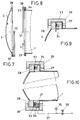
- Gemäss Fig. 1 und Fig. 2 ist ein Behälter 1 durch einen Deckel 2 verschlossen. Dieser Deckel ist gemäss Fig. 2 um zwei Achsen 3 auf zwei Gelenkböcken 4 schwenkbar gelagert. Die beiden Gelenkböcke 4 können mit Hilfe zweier Gewindespindeln 5 gehoben und gesenkt werden. Die beiden Gewindespindeln 5 sind in je einer Gewindebohrung 6 des Gelenkbockes 4 eingeschraubt. Durch Drehen der beiden Gewindespindeln 5 in der einen oder anderen Drehrichtung können somit die beiden Gewindeböcke 4 gehoben und gesenkt werden, wobei über die Achsen 3 auch der Deckel 2 des Behälters 1 gehoben oder gesenkt wird. Zum Drehen der beiden Gewindespindeln 5 sind an ihren unteren Enden je ein Winkelgetriebe 7 befestigt, welche über ein zweites Winkelgetriebe 8 von einem Elektromotor 9 angetrieben werden. Die beiden Winkelgetriebe 7 sind über je eine Welle 10 mit dem zweiten Winkelgetriebe 8 verbunden. Das Winkelgetriebe 7 weist zwei Kegelräder 11 und 12 auf, von denen das eine 11 an der Gewindespindel 5 und das andere an der Welle 10 befestigt ist. - Das Winkelgetriebe 8 weist drei Kegelräder 13, 14 und 15 auf. Die beiden Kegelräder 13 und 15 sind an der Welle 10 befestigt, das dritte Kegelrad 14 wird vom Elektromotor 9 angetrieben.
- Gemäss Fig. 1 ist jeder Gelenkbock 4 in zwei Führungsstangen 16 und 17 verschiebbar gelagert, wie auch aus Fig. 4 und Fig 5 ersichtlich ist. Gemäss Fig. 5 ist die Achse 3 starr am Deckel 2 befestigt und über einen Stift 18 schwenkbar im Gelenkbock 4 gelagert.
- Gemäss Fig. 3 ist am Deckel 2 über ein Gelenk 19 ein Schwenkarm 20 schwenkbar angelenkt. Dieser Schwenkarm 20 ist ferner in einem zweiten Gelenk 21 verschiebbar am Behälter 1 angelenkt. Der Schwenkarm 20 lässt sich in Richtung des Pfeils A im Gelenk 21 verschieben und kann zugleich wie durch Pfeil B angedeutet um eine Achse 22 schwenken. Durch einen Anschlag 23 ist die Verschiebung des Schwenkarmes 20 im Gelenk 21 begrenzt. Am rechten Ende des Schwenkarmes 20 ist eine Rolle 24. Diese Rolle 24 kann sich auf einem bogenförmigen Gleitsegment 25 abstützen, wenn sich der Schwenkarm 20 in der vertikalen, gestrichelt angedeuteten Stellung befindet, in welcher der ebenfalls gestrichelt angedeutete Behälter-Deckel 2 offen ist.
- Gemäss Fig. 6 kann die Rolle 24 des Schwenkarmes 20 in einer Führungskulisse 26 geführt sein, um den Behälter-Deckel 2 in seiner offenen Stellung gegen jede unerwünschte Verschwenkung zu sichern.
- Gemäss Fig. 7 und Fig. 8 ist am Behälter 1 der Behälter-Deckel 2 in Richtung eines Pfeils C einsetzbar. Am Behälter 1 ist ein Umfangsflansch 27 befestigt. Dieser Flansch 27 erstreckt sich über den ganzen Umfang des Behälters und weist einen rechteckigen querschnitt auf. Am Deckel 2 ist ebenfalls ein über den ganzen Deckelumfang sich erstreckender Umfangflansch 28 befestigt. Diese beiden Flansche weisen den gleichen querschnitt auf.
- Die Verriegelung der Vorrichtung wird anhand Fig. 7 und Fig. 8 näher erläutert. Diese Verriegelung ist ausführlich in der CH -A5- 420 893 beschrieben. Gemäss Fig. 7 und Fig. 8 ist der Deckel 2 durch zwei die beiden Umfangflanschen 27 und 28 übergreifenden Schliessringe 29 und 30 am Behälter 1 befestigt. Diese Schliessringe 29 und 30 bilden zwei Teilringe, die sich zusammen zum gesamten Umfang ergänzen. Jeder Schliessring 29 und 30 erstreckt sich somit über einen Umfangswinkel von 180°. Der Schliessring 29 ist über seine ganze Länge, z.B. mittels einer Schweissnaht, am Flansch 27 des Behälters 1 befestigt und der Schliessring 30 ist über seine ganze Länge mittels einer Schweissnaht am Flansch 28 des Deckels 2 befestigt. Die beiden Schliessringe 29 und 30 weisen einen U-förmigen querschnitt auf und sind gleich ausgebildet. Beim Einsetzen des Deckels 2 liegen die Stirnflächen 31 des einen Schliessringes 29 an den Stirnflächen 32 des anderen Schliessringes 30 an. Ein Unterschied zwischen den Flanschen 27 und 28 besteht darin, dass sich im Gegensatz zum Flansch 28 im Flansch 27 ein Dichtungsring 33 befindet. Dieser Dichtungsring 33 ist in der die Trennebene zwischen Deckel 2 und Behälter 1 bildenden Stirnseite des Flanches 27 eingesetzt. Der Dichtungsring 33 erstreckt sich über den ganzen Umfang des Flansches 27. Fig. 9 und Fig. 10 zeigen detailliert diese Verriegelungsvorrichtung. Zwischen dem Dichtungsring 33 und dem Flansch 27 ist ein Druckluftraum 34 vorhanden.
- Dieser Druckluftraum 34 entsteht durch Einstechen einer Nut für den Dichtungsring 33, die tiefer ist als der eingesetzte Teil des Dichtungsringes 33. Der Dichtungsring 33 ist bei angelegtem Deckel 2 mittels Druckluft in Längsrichtung des Behälters 1 verschiebbar geführt und tritt dann etwas aus der Stirnfläche des Flansches 27.
- Die Druckluft kann gemäss Fig. 10 durch einen Druckwächter 35 und durch ein Magnetventil 36 gesteuert werden. Das Magnetventil 36 befindet sich in einer Druckluftleitung 37, welche zur Umfangsnut 34 des Flansches 27 führt.
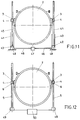
- Beim Ausführungsbeispiel gemäss Fig. 11 ist der Deckel 2 ebenfalls um zwei Achsen 3 auf zwei Gelenkböcken 4 schwenkbar gelagert. Die beiden Gelenkböcke 4 können mit Hilfe zweier Hubzylinder 40 und 41 angehoben und gesenkt werden. Die beiden Hubzylinder 40 und 41 sind ortsfest und enthalten je einen Kolben 42 und 43. Diese beiden Kolben 42 und 43 sind über je eine Kolbenstange 44 und 45 mit den Gelenkböcken 4 verbunden. Jeder Hubzylinder 40 und 41 ist über eine hydraulische Leitung 46 an einer Hydraulikpumpe 47 angeschlossen, damit beim Einschalten dieser Hydraulikpumpe 47 Druckflüssigkeit in die Kammern 48 der Hydraulikzylinder 40 und 41 unterhalb den Kolben 42 und 43 zugeführt werden kann. Dadurch werden die Kolben 42 und 43 angehoben und über die Kolbenstange 44 und 45 werden die Gelenkböcke 4 und somit auch der Behälter-Deckel 2 angehoben.
- Beim Ausführungsbeispiel gemäss Fig. 12 ist der Deckel 2 wiederum um zwei Achsen 3 auf zwei Gelenkböcken 4 schwenkbar gelagert. Die beiden Gelenkböcke 4 können mit Hilfe zweier Gewindespindeln 5 gehoben und gesenkt werden. Die beiden Gewindespindeln 5 sind in je einer Gewindebohrung 6 des Gelenkbockes 4 eingeschraubt. Durch Drehen der beiden Gewindespindeln 5 in der einen oder anderen Drehrichtung können somit die beiden Gewindeböcke 4 gehoben und gesenkt werden, wobei über die Achsen 3 auch der Deckel 2 des Behälters 1 gehoben oder gesenkt wird. Zum Drehen der beiden Gewindespindeln 5 sind an ihren unteren Enden je ein Elektromotor 49 angeordnet, mit deren Hilfe die beiden Gewindespindeln in beiden Drehrichtungen angetrieben werden können. Eine an sich bekannte Schaltvorrichtung 50 gewährleistet, dass die beiden Elektromotoren 49 synchron angetrieben werden. Im übrigen funktioniert diese Ausführungsform genau gleich wie die in Fig. 2 dargestellte Ausführungsform.
- Das Öffnen und Schliessen des Behälters 1 durch den Deckel 2 geht folgendermassen vor sich: Bevor der Deckel 2 zum Öffnen des Behälters 1 verschoben werden kann, muss zuerst der im Behälter 1 herrschende Druck oder das im Behälter 1 vorhandene Vakuum vollständig abgebaut werden. Anschliessend muss auch der Druck im Druckluftraum 34 hinter dem Dichtungsring 33 abgebaut werden, damit der Dichtungsring 33 nicht mehr gegen den Umfangflansch 28 angepresst wird. Der Deckel 2 lässt sich beim Öffnen des Behälters 1 erst verschieben, wenn der Druckwächter 35 anzeigt, dass durch das Magnetventil 36 die Leitung 37 und somit der Druckluftraum 34 vollständig entlüftet sind.
- Beim Verschieben des Deckels 2 zum Öffnen des Behälters 1 wird der Motor 9 eingeschaltet und der Deckel 2 beginnt sich in Richtung des Pfeils C (Fig. 7) zu verschieben. Bei dieser Verschiebung wird der halbe, ohne Schliessring versehene Umfang des Flansches 28 aus dem Schliessring 29 des Behälters 1 herausgezogen, ebenfalls wird der andere halbe ohne Schliessring 29 versehene Umfang des Flansches 27 aus dem Schliessring 30 des Deckels 2 herausgeschoben.
- Wenn der Behälter 1 durch den Deckel 2 geschlossen ist, kann ein Druck im Behälter 1 aufgebaut werden, dann berühren sich die Flansche 27 und 28 nicht, wie aus Fig. 9 ersichtlich ist.
- Wenn der Behälter 1 durch den Deckel 2 geschlossen ist, kann aber auch ein Vakuum im Behälter 1 erzeugt werden, dann werden die Flansche 27 und 28 aneinander gepresst, wie aus Fig. 10 ersichtlich ist. In beiden Fällen wird im Druckluftraum 34 ein Druck erzeugt und der Dichtring 33 wird gegen den Flansch 28 gepresst, wodurch gewährleistet ist, dass der Deckel 2 dicht am Behälter 1 anliegt.
- Statt durch einen einzigen Motor 9 können die beiden Spindeln 5 durch je einen separaten Motor synchron angetrieben werden. Statt der Spindeln 5 können die Gelenkböcke 4 mit dem Deckel 2 durch zwei hydraulische oder pneumatische Zylinder mit je einem Kolben gehoben werden oder mit Hilfe von Zahnstangen.
- Der Behälter 1 hat beispielsweise einen Durchmesser von 2,7 Metern und ist so stark, dass er mindestens Drücke von +4 bar und ein entsprechendes Vakuum von -1 bar ohne Deformation aushält. Die Länge des Behälters beträgt beispielsweise 2-10 Meter. Aus Festigkeitsgründen ist der Deckel 2 nicht flach sondern kalottenförmig. Für den Dichtring 33 zwischen Behälter 1 und Deckel 2, d.h. zwischen dem Umfangsflansch 27 am Behälter 1 und dem Umfangsflansch 28 am Deckel 2, wird vorzugsweise ein sogenannter O-Ring aus Gummi oder ein geeigneten Kunststoff, z.B. syntetischer Gummi, verwendet. Zum Verschieben und Verschwenken des Behälter-Deckels 2 eignen sich Elektromotren oder Hydromotoren, deren Grösse vom Gewicht des Deckels 2 abhängig ist. Im Druckluftraum 34 hinter dem Dichtungsring 33 herrscht beispielweise ein Druck von 4 bis 8 bar.
Claims (8)
- Vorrichtung zum Verschieben und Schwenken eines deckelförmigen Verschlusses an einem Behälter, wobei der Behälterverschluss mit einer Verriegelungsvorrichtung versehen ist, welche bei einem Über- und Unterdruck abdichtet, dadurch gekennzeichnet, dass ausserhalb des Behälters (1) wenigstens eine Verschiebevorrichtung (4,5) vorgesehen ist, welche einen am Behälterverschluss (2) angeordneten Gelenkbock (4) aufweist, und welcher auf zwei zueinander parallel angeordneten Führungsstangen (16,17) geführt ist, dass zusätzlich am Behälter-Verschluss (2), ausserhalb des Behälters, wenigstens ein Gelenk (19) mit einem darin endseitig gelagerten Schwenkkarm (20) vorgesehen ist und dass dieser auf einem verschiebbaren weiteren Gelenk (21) am Behälter (1) schwenkbar angelenkt ist.
- Vorrichtung nach Anspruch 1, dadurch gekennzeichnet, dass zu beiden Seiten des Behälter-Verschlusses (2) je eine Spindel (5) zu dessen Verschieben angeordnet ist, welche synchron angetrieben werden, und dass ebenfalls zu beiden Seiten des Behälter-Verschlusses (2) je ein Schwenkarm (20) und je zwei Führungsstangen (16,17) angeordnet sind.
- Vorrichtung nach Anspruch 2, dadurch gekennzeichnet, dass die beiden Spindeln (5) von einem gemeinsamen Motor (9) über ein Winkelgetriebe (7,8) synchron angetrieben werden.
- Vorrichtung nach Anspruch 2, dadurch gekennzeichnet, dass jede Spindel (5) durch einen eigenen Motor (49) angetrieben ist und dass die beiden Motoren (49) synchron drehen.
- Vorrichtung nach Anspruch 1, dadurch gekennzeichnet, dass zu beiden Seiten des Behälter-Verschlusses (2) je ein hydraulischer Hubzylinder angeordnet ist mit einem Kolben zum Verschieben des Behälter-Verschlusses (2).
- Vorrichtung nach Anspruch 2, dadurch gekennzeichnet, dass der Schwenkarm eine Gleitrolle (24) aufweist, welche sich über einen Teilbereich der Schwenkbewegung des Schwenkarmes (20) auf einem Gleitsegment (25) abstützt.
- Vorrichtung nach Anspruch 2, dadurch gekennzeichnet, dass der Schwenkarm eine Gleitrolle (24) aufweist, welche sich über einen Teilbereich der Schwenkbewegung des Schwenkarmes auf einer Führungskulisse (26) abstützt.
- Vorrichtung nach Anspruch 1, wobei die Verriegelungsvorrichtung je einen Umfangsflansch am Behälter-Verschluss und am Behälter aufweist und mit einem die beiden Umfangsflansche übergreifenden Schliessring zum Zusammenhalten von Behälter und Deckel versehen ist, dadurch gekennzeichnet, dass der Schliessring aus zwei sich zum gesamten Umfang ergänzenden Schliessringen (29,30) besteht und dass der eine Schliessring (30) am Behälter-Verschluss (2) und der andere Schliessring (29) am Behälter (1) befestigt ist zum hakenartigen Untergreifen der Umfangsflansche (27,28) an den Schliessringen (29,30) beim Verschieben des Deckels (2) quer zur Öffnung des Behälters (1).
Applications Claiming Priority (2)
| Application Number | Priority Date | Filing Date | Title |
|---|---|---|---|
| CH645/91 | 1991-03-04 | ||
| CH645/91A CH684402A5 (de) | 1991-03-04 | 1991-03-04 | Vorrichtung zum Verschieben und Schwenken eines Behälter-Verschlusses. |
Publications (2)
| Publication Number | Publication Date |
|---|---|
| EP0502822A1 EP0502822A1 (de) | 1992-09-09 |
| EP0502822B1 true EP0502822B1 (de) | 1996-07-24 |
Family
ID=4191836
Family Applications (1)
| Application Number | Title | Priority Date | Filing Date |
|---|---|---|---|
| EP92810144A Expired - Lifetime EP0502822B1 (de) | 1991-03-04 | 1992-02-27 | Vorrichtung zum Verschieben und Schwenken eines Behälter-Verschlusses |
Country Status (8)
| Country | Link |
|---|---|
| US (1) | US5191993A (de) |
| EP (1) | EP0502822B1 (de) |
| AT (1) | ATE140676T1 (de) |
| CH (1) | CH684402A5 (de) |
| DE (1) | DE59206794D1 (de) |
| DK (1) | DK0502822T3 (de) |
| ES (1) | ES2090566T3 (de) |
| GR (1) | GR3021066T3 (de) |
Families Citing this family (69)
| Publication number | Priority date | Publication date | Assignee | Title |
|---|---|---|---|---|
| DE4315505C2 (de) * | 1993-05-10 | 1998-09-17 | Aicher Max Entsorgungstechnik | Vorrichtung zum Öffnen eines Deckels, insbesondere für einen liegenden Müllcontainer |
| TW539918B (en) | 1997-05-27 | 2003-07-01 | Tokyo Electron Ltd | Removal of photoresist and photoresist residue from semiconductors using supercritical carbon dioxide process |
| US6334266B1 (en) | 1999-09-20 | 2002-01-01 | S.C. Fluids, Inc. | Supercritical fluid drying system and method of use |
| US6497239B2 (en) | 1999-08-05 | 2002-12-24 | S. C. Fluids, Inc. | Inverted pressure vessel with shielded closure mechanism |
| US6508259B1 (en) | 1999-08-05 | 2003-01-21 | S.C. Fluids, Inc. | Inverted pressure vessel with horizontal through loading |
| US6748960B1 (en) | 1999-11-02 | 2004-06-15 | Tokyo Electron Limited | Apparatus for supercritical processing of multiple workpieces |
| EP1234322A2 (de) * | 1999-11-02 | 2002-08-28 | Tokyo Electron Limited | Verfahren und vorrichtungen zur überkritischen verarbeitung von werkstücken |
| KR100750018B1 (ko) * | 2000-07-26 | 2007-08-16 | 동경 엘렉트론 주식회사 | 반도체 기판의 처리를 위한 고압 챔버 및 반도체 기판의고압 처리를 위한 장치 |
| US20040040660A1 (en) * | 2001-10-03 | 2004-03-04 | Biberger Maximilian Albert | High pressure processing chamber for multiple semiconductor substrates |
| US7001468B1 (en) | 2002-02-15 | 2006-02-21 | Tokyo Electron Limited | Pressure energized pressure vessel opening and closing device and method of providing therefor |
| AU2003215238A1 (en) * | 2002-02-15 | 2003-09-09 | Supercritical Systems Inc. | Pressure enchanced diaphragm valve |
| US7387868B2 (en) | 2002-03-04 | 2008-06-17 | Tokyo Electron Limited | Treatment of a dielectric layer using supercritical CO2 |
| US7121042B2 (en) * | 2002-11-15 | 2006-10-17 | Steris Inc. | Door assembly for sealing a chamber |
| US7021635B2 (en) * | 2003-02-06 | 2006-04-04 | Tokyo Electron Limited | Vacuum chuck utilizing sintered material and method of providing thereof |
| US7077917B2 (en) * | 2003-02-10 | 2006-07-18 | Tokyo Electric Limited | High-pressure processing chamber for a semiconductor wafer |
| US7225820B2 (en) * | 2003-02-10 | 2007-06-05 | Tokyo Electron Limited | High-pressure processing chamber for a semiconductor wafer |
| US7270137B2 (en) | 2003-04-28 | 2007-09-18 | Tokyo Electron Limited | Apparatus and method of securing a workpiece during high-pressure processing |
| DE10328154A1 (de) * | 2003-06-07 | 2004-12-23 | Günter Volland | Bombenschutzbehälter |
| GB0314745D0 (en) * | 2003-06-25 | 2003-07-30 | Tanker Solutions Ltd | Hatch cover apparatus |
| US7163380B2 (en) | 2003-07-29 | 2007-01-16 | Tokyo Electron Limited | Control of fluid flow in the processing of an object with a fluid |
| US20050035514A1 (en) * | 2003-08-11 | 2005-02-17 | Supercritical Systems, Inc. | Vacuum chuck apparatus and method for holding a wafer during high pressure processing |
| US20050034660A1 (en) * | 2003-08-11 | 2005-02-17 | Supercritical Systems, Inc. | Alignment means for chamber closure to reduce wear on surfaces |
| US20050067002A1 (en) * | 2003-09-25 | 2005-03-31 | Supercritical Systems, Inc. | Processing chamber including a circulation loop integrally formed in a chamber housing |
| US7186093B2 (en) * | 2004-10-05 | 2007-03-06 | Tokyo Electron Limited | Method and apparatus for cooling motor bearings of a high pressure pump |
| US7250374B2 (en) * | 2004-06-30 | 2007-07-31 | Tokyo Electron Limited | System and method for processing a substrate using supercritical carbon dioxide processing |
| US7307019B2 (en) * | 2004-09-29 | 2007-12-11 | Tokyo Electron Limited | Method for supercritical carbon dioxide processing of fluoro-carbon films |
| US20060065288A1 (en) * | 2004-09-30 | 2006-03-30 | Darko Babic | Supercritical fluid processing system having a coating on internal members and a method of using |
| US20060065189A1 (en) * | 2004-09-30 | 2006-03-30 | Darko Babic | Method and system for homogenization of supercritical fluid in a high pressure processing system |
| US7484322B2 (en) | 2004-10-22 | 2009-02-03 | Mclaughlin Group, Inc. | Digging and backfill apparatus |
| US7491036B2 (en) * | 2004-11-12 | 2009-02-17 | Tokyo Electron Limited | Method and system for cooling a pump |
| US20060102204A1 (en) * | 2004-11-12 | 2006-05-18 | Tokyo Electron Limited | Method for removing a residue from a substrate using supercritical carbon dioxide processing |
| US20060102208A1 (en) * | 2004-11-12 | 2006-05-18 | Tokyo Electron Limited | System for removing a residue from a substrate using supercritical carbon dioxide processing |
| US20060102591A1 (en) * | 2004-11-12 | 2006-05-18 | Tokyo Electron Limited | Method and system for treating a substrate using a supercritical fluid |
| US20060102590A1 (en) * | 2004-11-12 | 2006-05-18 | Tokyo Electron Limited | Method for treating a substrate with a high pressure fluid using a preoxide-based process chemistry |
| US7140393B2 (en) * | 2004-12-22 | 2006-11-28 | Tokyo Electron Limited | Non-contact shuttle valve for flow diversion in high pressure systems |
| US20060134332A1 (en) * | 2004-12-22 | 2006-06-22 | Darko Babic | Precompressed coating of internal members in a supercritical fluid processing system |
| US20060135047A1 (en) * | 2004-12-22 | 2006-06-22 | Alexei Sheydayi | Method and apparatus for clamping a substrate in a high pressure processing system |
| US7434590B2 (en) * | 2004-12-22 | 2008-10-14 | Tokyo Electron Limited | Method and apparatus for clamping a substrate in a high pressure processing system |
| US7291565B2 (en) * | 2005-02-15 | 2007-11-06 | Tokyo Electron Limited | Method and system for treating a substrate with a high pressure fluid using fluorosilicic acid |
| US20060180572A1 (en) * | 2005-02-15 | 2006-08-17 | Tokyo Electron Limited | Removal of post etch residue for a substrate with open metal surfaces |
| US20060180174A1 (en) * | 2005-02-15 | 2006-08-17 | Tokyo Electron Limited | Method and system for treating a substrate with a high pressure fluid using a peroxide-based process chemistry in conjunction with an initiator |
| US7435447B2 (en) * | 2005-02-15 | 2008-10-14 | Tokyo Electron Limited | Method and system for determining flow conditions in a high pressure processing system |
| US7767145B2 (en) | 2005-03-28 | 2010-08-03 | Toyko Electron Limited | High pressure fourier transform infrared cell |
| US7380984B2 (en) * | 2005-03-28 | 2008-06-03 | Tokyo Electron Limited | Process flow thermocouple |
| US20060226117A1 (en) * | 2005-03-29 | 2006-10-12 | Bertram Ronald T | Phase change based heating element system and method |
| US20060225772A1 (en) * | 2005-03-29 | 2006-10-12 | Jones William D | Controlled pressure differential in a high-pressure processing chamber |
| US7494107B2 (en) | 2005-03-30 | 2009-02-24 | Supercritical Systems, Inc. | Gate valve for plus-atmospheric pressure semiconductor process vessels |
| US20060255012A1 (en) * | 2005-05-10 | 2006-11-16 | Gunilla Jacobson | Removal of particles from substrate surfaces using supercritical processing |
| US7789971B2 (en) * | 2005-05-13 | 2010-09-07 | Tokyo Electron Limited | Treatment of substrate using functionalizing agent in supercritical carbon dioxide |
| US7524383B2 (en) * | 2005-05-25 | 2009-04-28 | Tokyo Electron Limited | Method and system for passivating a processing chamber |
| US20070012337A1 (en) * | 2005-07-15 | 2007-01-18 | Tokyo Electron Limited | In-line metrology for supercritical fluid processing |
| US7837050B2 (en) * | 2006-10-06 | 2010-11-23 | McLaughlin Group, Inc | Collection tank |
| US20080244859A1 (en) * | 2007-04-03 | 2008-10-09 | Charles Robert Maybury | Vacuum system with improved mobility |
| ITBS20090032A1 (it) * | 2009-02-25 | 2010-08-26 | Cattaruzzi Internat S R L | Impianto per lo stordimento e/o abbattimento di animali da macellazione |
| US9821953B2 (en) | 2011-05-02 | 2017-11-21 | The Charles Machine Works, Inc. | Apparatus for sealing a vacuum tank door |
| US9057180B1 (en) * | 2011-05-02 | 2015-06-16 | The Charles Machine Works, Inc. | Apparatus for sealing a vacuum tank door |
| WO2013016941A1 (zh) * | 2011-07-29 | 2013-02-07 | 无锡华瑛微电子技术有限公司 | 可调式半导体处理装置及其控制方法 |
| US9103091B2 (en) | 2012-04-30 | 2015-08-11 | Vac-Tron Equipment, Llc | System and method to excavate and fill |
| US9382688B2 (en) | 2012-06-26 | 2016-07-05 | Vac-Tron Equipment, Llc | System and method to excavate using pneumatic shock wave |
| US9056266B2 (en) | 2012-07-21 | 2015-06-16 | Don M. Buckner | Method and system to separate solids from liquids |
| US10166556B2 (en) | 2012-08-07 | 2019-01-01 | Vac-Tron Equipment, Llc | Pulsating high pressure air and water nozzle |
| US9931649B2 (en) | 2012-08-07 | 2018-04-03 | Vac-Tron Equipment, Llc | Rotating high pressure air and water nozzle |
| US8584795B1 (en) | 2012-09-04 | 2013-11-19 | Vac-Tron Equipment, Llc | Filter silencer |
| US10221602B2 (en) | 2016-04-06 | 2019-03-05 | The Charles Machine Works, Inc. | Vacuum system |
| RU2690938C2 (ru) * | 2017-04-12 | 2019-06-06 | Общество с ограниченной ответственностью "РэйлТрансЛизинг" (ООО "РэйлТрансЛизинг") | Затвор люка емкости и коромысло затвора люка емкости |
| US11059682B2 (en) | 2017-12-21 | 2021-07-13 | The Charles Machine Works, Inc. | Offloading vacuum tank |
| USD895914S1 (en) | 2018-02-15 | 2020-09-08 | The Charles Machine Works, Inc. | Vacuum system |
| US11801785B2 (en) | 2020-06-17 | 2023-10-31 | Vermeer Manufacturing Company | Vacuum excavator tank and door system |
| CN116620741B (zh) * | 2023-07-24 | 2023-09-19 | 江苏大敬生物科技股份有限公司 | 一种茶多酚常温贮藏装置 |
Family Cites Families (13)
| Publication number | Priority date | Publication date | Assignee | Title |
|---|---|---|---|---|
| US1819104A (en) * | 1930-08-05 | 1931-08-18 | Lipovsky John | Closure operator and retaining means |
| US3119512A (en) * | 1960-05-31 | 1964-01-28 | Robert D Foster | Quick closure and connecting arrangement for members |
| US3302331A (en) * | 1960-07-15 | 1967-02-07 | Sturm | Door mechanism |
| US3195761A (en) * | 1962-02-09 | 1965-07-20 | John N Coats | Digester cap assembly |
| US3349947A (en) * | 1964-09-08 | 1967-10-31 | Arlie I Zumwalt | Closure |
| FR2080275A6 (fr) * | 1965-03-30 | 1971-11-12 | Bellot Jean | Porte ou trappe à ouverture progressive |
| US4334633A (en) * | 1981-04-06 | 1982-06-15 | Wsf Industries, Inc. | Articulated door |
| AU525595B3 (en) * | 1982-05-14 | 1982-10-07 | Thirteenth Martex Pty. Ltd. | Hinged lid |
| DE3623874A1 (de) * | 1986-07-15 | 1988-01-28 | Graaff Kg | Grossbehaelter |
| DE3632983A1 (de) * | 1986-09-29 | 1988-03-31 | Krupp Koppers Gmbh | Einrichtung zur montage und demontage von an apparaten, behaeltern oder dgl. senkrecht angeordneten deckeln |
| GB2214903B (en) * | 1988-02-25 | 1991-12-18 | Ind Tech Res Inst | Collapsible container |
| US5092963A (en) * | 1989-02-21 | 1992-03-03 | Atlantic Richfield Company | Automated top head and stem guide assembly for coking drums |
| US4957039A (en) * | 1990-01-17 | 1990-09-18 | Reyes Clyde L | Five in one cooker |
-
1991
- 1991-03-04 CH CH645/91A patent/CH684402A5/de not_active IP Right Cessation
-
1992
- 1992-02-24 US US07/840,462 patent/US5191993A/en not_active Expired - Lifetime
- 1992-02-27 DK DK92810144.3T patent/DK0502822T3/da active
- 1992-02-27 ES ES92810144T patent/ES2090566T3/es not_active Expired - Lifetime
- 1992-02-27 DE DE59206794T patent/DE59206794D1/de not_active Expired - Fee Related
- 1992-02-27 EP EP92810144A patent/EP0502822B1/de not_active Expired - Lifetime
- 1992-02-27 AT AT92810144T patent/ATE140676T1/de not_active IP Right Cessation
-
1996
- 1996-09-18 GR GR960402434T patent/GR3021066T3/el unknown
Also Published As
| Publication number | Publication date |
|---|---|
| DK0502822T3 (da) | 1996-11-25 |
| GR3021066T3 (en) | 1996-12-31 |
| ES2090566T3 (es) | 1996-10-16 |
| US5191993A (en) | 1993-03-09 |
| ATE140676T1 (de) | 1996-08-15 |
| DE59206794D1 (de) | 1996-08-29 |
| CH684402A5 (de) | 1994-09-15 |
| EP0502822A1 (de) | 1992-09-09 |
Similar Documents
| Publication | Publication Date | Title |
|---|---|---|
| EP0502822B1 (de) | Vorrichtung zum Verschieben und Schwenken eines Behälter-Verschlusses | |
| DE60312344T2 (de) | Verschluss für einen druckbehälter und verfahren | |
| EP0279237B1 (de) | Drehantrieb zum Bewegen eines Schwenktürflügels, insbesondere an Fahrzeugen | |
| DE1286360B (de) | Flachdrehschieber | |
| DE2555207A1 (de) | Pneumatische klemmvorrichtung | |
| DE1958939A1 (de) | Vorrichtung zum Glaetten und Entgraten | |
| EP1126938B1 (de) | Bördel- und/oder falzschliessmaschine sowie betriebsverfahren | |
| DE2427316A1 (de) | Vorrichtung zum steuern eines hubzylinders | |
| DE1459044B2 (de) | Vorrichtung zum andruecken von tuerfluegeln in den tuerrahmen in der schliesslage | |
| DE2213314C2 (de) | Vorrichtung zum Betätigen von Flügeln, insbesondere von Türen und Gittertüren | |
| EP3243986A1 (de) | Feststelleinrichtung | |
| DE1965077A1 (de) | Vorrichtung zur Verriegelung des Kolbens eines Zylinders in beliebigen Stellungen | |
| DE1605012C3 (de) | Fahrzeug, insbesondere Eisenbahnwagen mit aufklappbarem Dach | |
| DE2456186C3 (de) | Betätigungsvorrichtung für den Deckel eines Munitionsmagazins für ein gepanzertes Landfahrzeug | |
| DE4113019A1 (de) | Klappenventil | |
| EP0343516B1 (de) | Fahrzeug mit Ladefläche | |
| DE2050761A1 (de) | Vorrichtung zur Bewegungssteuerung mittels eines hydraulischen Druckzylin ders | |
| DE1406687A1 (de) | Vorrichtung an Ladeluken mit hydraulischen Organen zum Auf- und Zuklappen der Lukendeckel | |
| DE2731163A1 (de) | Fenster | |
| DE1655713C3 (de) | Fahrzeug-Lüftungsklappe oder -fenster | |
| DE3227697C2 (de) | Vorrichtung zum Auswechseln einer in eine Rohrleitung eingeschalteten Meßblende | |
| DE673002C (de) | Vorrichtung zum OEffnen und Schliessen von Fenstern, insbesondere fuer Kraftwagen | |
| DE3237226A1 (de) | Anpressbares schiebefenster | |
| DE956672C (de) | Verriegelungsvorrichtung fuer Autoklavendeckel od. dgl. | |
| DE2457330B2 (de) | Vorrichtung zum öffnen und Schließen der Türe eines Koksofens |
Legal Events
| Date | Code | Title | Description |
|---|---|---|---|
| PUAI | Public reference made under article 153(3) epc to a published international application that has entered the european phase |
Free format text: ORIGINAL CODE: 0009012 |
|
| AK | Designated contracting states |
Kind code of ref document: A1 Designated state(s): AT BE CH DE DK ES FR GB GR IT LI LU MC NL PT SE |
|
| RAP1 | Party data changed (applicant data changed or rights of an application transferred) |
Owner name: KUENY MASCHINENBAU |
|
| RAP1 | Party data changed (applicant data changed or rights of an application transferred) |
Owner name: XORELLA AG |
|
| 17P | Request for examination filed |
Effective date: 19921021 |
|
| 17Q | First examination report despatched |
Effective date: 19941209 |
|
| GRAH | Despatch of communication of intention to grant a patent |
Free format text: ORIGINAL CODE: EPIDOS IGRA |
|
| GRAH | Despatch of communication of intention to grant a patent |
Free format text: ORIGINAL CODE: EPIDOS IGRA |
|
| GRAA | (expected) grant |
Free format text: ORIGINAL CODE: 0009210 |
|
| AK | Designated contracting states |
Kind code of ref document: B1 Designated state(s): AT BE CH DE DK ES FR GB GR IT LI LU MC NL PT SE |
|
| REF | Corresponds to: |
Ref document number: 140676 Country of ref document: AT Date of ref document: 19960815 Kind code of ref document: T |
|
| REG | Reference to a national code |
Ref country code: CH Ref legal event code: NV Representative=s name: PPS POLYVALENT PATENT SERVICE AG |
|
| ET | Fr: translation filed | ||
| GBT | Gb: translation of ep patent filed (gb section 77(6)(a)/1977) |
Effective date: 19960801 |
|
| REF | Corresponds to: |
Ref document number: 59206794 Country of ref document: DE Date of ref document: 19960829 |
|
| ITF | It: translation for a ep patent filed |
Owner name: ING. ZINI MARANESI & C. S.R.L. |
|
| REG | Reference to a national code |
Ref country code: ES Ref legal event code: FG2A Ref document number: 2090566 Country of ref document: ES Kind code of ref document: T3 |
|
| REG | Reference to a national code |
Ref country code: ES Ref legal event code: FG2A Ref document number: 2090566 Country of ref document: ES Kind code of ref document: T3 |
|
| REG | Reference to a national code |
Ref country code: DK Ref legal event code: T3 |
|
| REG | Reference to a national code |
Ref country code: GR Ref legal event code: FG4A Free format text: 3021066 |
|
| REG | Reference to a national code |
Ref country code: PT Ref legal event code: SC4A Free format text: AVAILABILITY OF NATIONAL TRANSLATION Effective date: 19961018 |
|
| PLBE | No opposition filed within time limit |
Free format text: ORIGINAL CODE: 0009261 |
|
| STAA | Information on the status of an ep patent application or granted ep patent |
Free format text: STATUS: NO OPPOSITION FILED WITHIN TIME LIMIT |
|
| 26N | No opposition filed | ||
| REG | Reference to a national code |
Ref country code: GB Ref legal event code: IF02 |
|
| PGFP | Annual fee paid to national office [announced via postgrant information from national office to epo] |
Ref country code: PT Payment date: 20070126 Year of fee payment: 16 Ref country code: MC Payment date: 20070126 Year of fee payment: 16 Ref country code: GB Payment date: 20070126 Year of fee payment: 16 |
|
| PGFP | Annual fee paid to national office [announced via postgrant information from national office to epo] |
Ref country code: ES Payment date: 20070207 Year of fee payment: 16 |
|
| PGFP | Annual fee paid to national office [announced via postgrant information from national office to epo] |
Ref country code: AT Payment date: 20070209 Year of fee payment: 16 |
|
| PGFP | Annual fee paid to national office [announced via postgrant information from national office to epo] |
Ref country code: SE Payment date: 20070212 Year of fee payment: 16 |
|
| PGFP | Annual fee paid to national office [announced via postgrant information from national office to epo] |
Ref country code: DK Payment date: 20070213 Year of fee payment: 16 Ref country code: LU Payment date: 20070213 Year of fee payment: 16 Ref country code: BE Payment date: 20070213 Year of fee payment: 16 |
|
| PGFP | Annual fee paid to national office [announced via postgrant information from national office to epo] |
Ref country code: NL Payment date: 20070214 Year of fee payment: 16 |
|
| PGFP | Annual fee paid to national office [announced via postgrant information from national office to epo] |
Ref country code: CH Payment date: 20070407 Year of fee payment: 16 |
|
| PGFP | Annual fee paid to national office [announced via postgrant information from national office to epo] |
Ref country code: DE Payment date: 20070425 Year of fee payment: 16 |
|
| PGFP | Annual fee paid to national office [announced via postgrant information from national office to epo] |
Ref country code: IT Payment date: 20070619 Year of fee payment: 16 |
|
| PGFP | Annual fee paid to national office [announced via postgrant information from national office to epo] |
Ref country code: GR Payment date: 20070226 Year of fee payment: 16 |
|
| PGFP | Annual fee paid to national office [announced via postgrant information from national office to epo] |
Ref country code: FR Payment date: 20070209 Year of fee payment: 16 |
|
| BERE | Be: lapsed |
Owner name: XORELLA A.G. Effective date: 20080228 |
|
| REG | Reference to a national code |
Ref country code: PT Ref legal event code: MM4A Free format text: LAPSE DUE TO NON-PAYMENT OF FEES Effective date: 20080827 |
|
| REG | Reference to a national code |
Ref country code: DK Ref legal event code: EBP |
|
| REG | Reference to a national code |
Ref country code: CH Ref legal event code: PL |
|
| EUG | Se: european patent has lapsed | ||
| GBPC | Gb: european patent ceased through non-payment of renewal fee |
Effective date: 20080227 |
|
| PG25 | Lapsed in a contracting state [announced via postgrant information from national office to epo] |
Ref country code: PT Free format text: LAPSE BECAUSE OF NON-PAYMENT OF DUE FEES Effective date: 20080827 Ref country code: MC Free format text: LAPSE BECAUSE OF NON-PAYMENT OF DUE FEES Effective date: 20080228 Ref country code: LI Free format text: LAPSE BECAUSE OF NON-PAYMENT OF DUE FEES Effective date: 20080229 Ref country code: CH Free format text: LAPSE BECAUSE OF NON-PAYMENT OF DUE FEES Effective date: 20080229 |
|
| NLV4 | Nl: lapsed or anulled due to non-payment of the annual fee |
Effective date: 20080901 |
|
| PG25 | Lapsed in a contracting state [announced via postgrant information from national office to epo] |
Ref country code: NL Free format text: LAPSE BECAUSE OF NON-PAYMENT OF DUE FEES Effective date: 20080901 Ref country code: AT Free format text: LAPSE BECAUSE OF NON-PAYMENT OF DUE FEES Effective date: 20080227 |
|
| REG | Reference to a national code |
Ref country code: FR Ref legal event code: ST Effective date: 20081031 |
|
| PG25 | Lapsed in a contracting state [announced via postgrant information from national office to epo] |
Ref country code: SE Free format text: LAPSE BECAUSE OF NON-PAYMENT OF DUE FEES Effective date: 20080228 Ref country code: DK Free format text: LAPSE BECAUSE OF NON-PAYMENT OF DUE FEES Effective date: 20080229 Ref country code: DE Free format text: LAPSE BECAUSE OF NON-PAYMENT OF DUE FEES Effective date: 20080902 |
|
| PG25 | Lapsed in a contracting state [announced via postgrant information from national office to epo] |
Ref country code: BE Free format text: LAPSE BECAUSE OF NON-PAYMENT OF DUE FEES Effective date: 20080228 |
|
| PG25 | Lapsed in a contracting state [announced via postgrant information from national office to epo] |
Ref country code: FR Free format text: LAPSE BECAUSE OF NON-PAYMENT OF DUE FEES Effective date: 20080229 |
|
| REG | Reference to a national code |
Ref country code: ES Ref legal event code: FD2A Effective date: 20080228 |
|
| PG25 | Lapsed in a contracting state [announced via postgrant information from national office to epo] |
Ref country code: GR Free format text: LAPSE BECAUSE OF NON-PAYMENT OF DUE FEES Effective date: 20080903 Ref country code: GB Free format text: LAPSE BECAUSE OF NON-PAYMENT OF DUE FEES Effective date: 20080227 |
|
| PG25 | Lapsed in a contracting state [announced via postgrant information from national office to epo] |
Ref country code: ES Free format text: LAPSE BECAUSE OF NON-PAYMENT OF DUE FEES Effective date: 20080228 |
|
| PG25 | Lapsed in a contracting state [announced via postgrant information from national office to epo] |
Ref country code: IT Free format text: LAPSE BECAUSE OF NON-PAYMENT OF DUE FEES Effective date: 20080227 |
|
| PG25 | Lapsed in a contracting state [announced via postgrant information from national office to epo] |
Ref country code: LU Free format text: LAPSE BECAUSE OF NON-PAYMENT OF DUE FEES Effective date: 20080227 |