EP0503890A2 - Process and apparatus for producing dental filling for restoration of tooth crown - Google Patents
Process and apparatus for producing dental filling for restoration of tooth crown Download PDFInfo
- Publication number
- EP0503890A2 EP0503890A2 EP92302021A EP92302021A EP0503890A2 EP 0503890 A2 EP0503890 A2 EP 0503890A2 EP 92302021 A EP92302021 A EP 92302021A EP 92302021 A EP92302021 A EP 92302021A EP 0503890 A2 EP0503890 A2 EP 0503890A2
- Authority
- EP
- European Patent Office
- Prior art keywords
- tooth
- cutting
- cavity
- outline form
- batch
- Prior art date
- Legal status (The legal status is an assumption and is not a legal conclusion. Google has not performed a legal analysis and makes no representation as to the accuracy of the status listed.)
- Granted
Links
- 210000000332 tooth crown Anatomy 0.000 title claims abstract description 21
- 238000000034 method Methods 0.000 title claims abstract description 19
- 230000008569 process Effects 0.000 title claims abstract description 11
- 238000005520 cutting process Methods 0.000 claims abstract description 80
- 238000003754 machining Methods 0.000 claims abstract description 24
- 238000002360 preparation method Methods 0.000 claims abstract description 12
- 238000012544 monitoring process Methods 0.000 claims abstract description 10
- 238000006073 displacement reaction Methods 0.000 claims description 21
- 230000003100 immobilizing effect Effects 0.000 claims description 10
- 238000004519 manufacturing process Methods 0.000 description 21
- 239000000463 material Substances 0.000 description 21
- 229910052573 porcelain Inorganic materials 0.000 description 14
- 239000002184 metal Substances 0.000 description 7
- 230000003287 optical effect Effects 0.000 description 7
- 238000010304 firing Methods 0.000 description 5
- 238000000227 grinding Methods 0.000 description 5
- 230000007246 mechanism Effects 0.000 description 3
- 239000011505 plaster Substances 0.000 description 3
- 238000005266 casting Methods 0.000 description 2
- 238000007796 conventional method Methods 0.000 description 2
- 239000000543 intermediate Substances 0.000 description 2
- 239000013307 optical fiber Substances 0.000 description 2
- 239000011347 resin Substances 0.000 description 2
- 229920005989 resin Polymers 0.000 description 2
- 0 NC*C1CC1 Chemical compound NC*C1CC1 0.000 description 1
- 238000005299 abrasion Methods 0.000 description 1
- 239000000853 adhesive Substances 0.000 description 1
- 230000001070 adhesive effect Effects 0.000 description 1
- 239000000805 composite resin Substances 0.000 description 1
- 238000010276 construction Methods 0.000 description 1
- 238000005260 corrosion Methods 0.000 description 1
- 230000007797 corrosion Effects 0.000 description 1
- 208000002925 dental caries Diseases 0.000 description 1
- 238000001514 detection method Methods 0.000 description 1
- 238000001704 evaporation Methods 0.000 description 1
- 230000006870 function Effects 0.000 description 1
- 239000000203 mixture Substances 0.000 description 1
- 238000012986 modification Methods 0.000 description 1
- 230000004048 modification Effects 0.000 description 1
- 239000007787 solid Substances 0.000 description 1
Images


Classifications
-
- A—HUMAN NECESSITIES
- A61—MEDICAL OR VETERINARY SCIENCE; HYGIENE
- A61C—DENTISTRY; APPARATUS OR METHODS FOR ORAL OR DENTAL HYGIENE
- A61C13/00—Dental prostheses; Making same
- A61C13/0003—Making bridge-work, inlays, implants or the like
- A61C13/0004—Computer-assisted sizing or machining of dental prostheses
-
- A—HUMAN NECESSITIES
- A61—MEDICAL OR VETERINARY SCIENCE; HYGIENE
- A61B—DIAGNOSIS; SURGERY; IDENTIFICATION
- A61B34/00—Computer-aided surgery; Manipulators or robots specially adapted for use in surgery
- A61B34/20—Surgical navigation systems; Devices for tracking or guiding surgical instruments, e.g. for frameless stereotaxis
-
- A—HUMAN NECESSITIES
- A61—MEDICAL OR VETERINARY SCIENCE; HYGIENE
- A61C—DENTISTRY; APPARATUS OR METHODS FOR ORAL OR DENTAL HYGIENE
- A61C13/00—Dental prostheses; Making same
- A61C13/0003—Making bridge-work, inlays, implants or the like
-
- A—HUMAN NECESSITIES
- A61—MEDICAL OR VETERINARY SCIENCE; HYGIENE
- A61C—DENTISTRY; APPARATUS OR METHODS FOR ORAL OR DENTAL HYGIENE
- A61C5/00—Filling or capping teeth
- A61C5/70—Tooth crowns; Making thereof
- A61C5/77—Methods or devices for making crowns
-
- A—HUMAN NECESSITIES
- A61—MEDICAL OR VETERINARY SCIENCE; HYGIENE
- A61B—DIAGNOSIS; SURGERY; IDENTIFICATION
- A61B34/00—Computer-aided surgery; Manipulators or robots specially adapted for use in surgery
- A61B34/20—Surgical navigation systems; Devices for tracking or guiding surgical instruments, e.g. for frameless stereotaxis
- A61B2034/2046—Tracking techniques
- A61B2034/2055—Optical tracking systems
-
- A—HUMAN NECESSITIES
- A61—MEDICAL OR VETERINARY SCIENCE; HYGIENE
- A61B—DIAGNOSIS; SURGERY; IDENTIFICATION
- A61B34/00—Computer-aided surgery; Manipulators or robots specially adapted for use in surgery
- A61B34/20—Surgical navigation systems; Devices for tracking or guiding surgical instruments, e.g. for frameless stereotaxis
- A61B2034/2072—Reference field transducer attached to an instrument or patient
-
- A—HUMAN NECESSITIES
- A61—MEDICAL OR VETERINARY SCIENCE; HYGIENE
- A61B—DIAGNOSIS; SURGERY; IDENTIFICATION
- A61B90/00—Instruments, implements or accessories specially adapted for surgery or diagnosis and not covered by any of the groups A61B1/00 - A61B50/00, e.g. for luxation treatment or for protecting wound edges
- A61B90/36—Image-producing devices or illumination devices not otherwise provided for
- A61B2090/363—Use of fiducial points
-
- A—HUMAN NECESSITIES
- A61—MEDICAL OR VETERINARY SCIENCE; HYGIENE
- A61B—DIAGNOSIS; SURGERY; IDENTIFICATION
- A61B90/00—Instruments, implements or accessories specially adapted for surgery or diagnosis and not covered by any of the groups A61B1/00 - A61B50/00, e.g. for luxation treatment or for protecting wound edges
- A61B90/39—Markers, e.g. radio-opaque or breast lesions markers
- A61B2090/3937—Visible markers
- A61B2090/3945—Active visible markers, e.g. light emitting diodes
-
- A—HUMAN NECESSITIES
- A61—MEDICAL OR VETERINARY SCIENCE; HYGIENE
- A61C—DENTISTRY; APPARATUS OR METHODS FOR ORAL OR DENTAL HYGIENE
- A61C1/00—Dental machines for boring or cutting ; General features of dental machines or apparatus, e.g. hand-piece design
- A61C1/08—Machine parts specially adapted for dentistry
- A61C1/082—Positioning or guiding, e.g. of drills
-
- G—PHYSICS
- G16—INFORMATION AND COMMUNICATION TECHNOLOGY [ICT] SPECIALLY ADAPTED FOR SPECIFIC APPLICATION FIELDS
- G16H—HEALTHCARE INFORMATICS, i.e. INFORMATION AND COMMUNICATION TECHNOLOGY [ICT] SPECIALLY ADAPTED FOR THE HANDLING OR PROCESSING OF MEDICAL OR HEALTHCARE DATA
- G16H20/00—ICT specially adapted for therapies or health-improving plans, e.g. for handling prescriptions, for steering therapy or for monitoring patient compliance
- G16H20/40—ICT specially adapted for therapies or health-improving plans, e.g. for handling prescriptions, for steering therapy or for monitoring patient compliance relating to mechanical, radiation or invasive therapies, e.g. surgery, laser therapy, dialysis or acupuncture
Definitions
- the present invention generally relates to a process and an apparatus for producing a dental filling for restoration of a tooth crown, and particularly to the technique of producing such a dental filling with ease and with high form accuracy.
- metal is selected as filling material
- a model is used for forming a wax pattern corresponding to a tooth including a cavity; the wax pattern is immersed in a fireproof investment such as plaster; the plaster is heated for removing or evaporating the wax pattern and thereby obtaining a mold; the mold is used for casting the metal; and the cast metal is cut, ground and polished into a final, dental filling.
- porcelain it is common that a model is used for producing a secondary model; wet porcelain mix is applied to the cavity of the secondary model, and then they are fired; the fired porcelain is cut, ground and polished into a final dental filling.
- any of the known techniques in which various sorts of materials are used for producing a dental filling essentially requires taking an impression of a tooth, forming a model on the impression, and producing a pattern or a secondary model using the model.
- those techniques are very cumbersome to carry out, need a long time, and high in cost.
- the present invention has been developed. It is therefore an object of the present invention to provide a process and an apparatus for producing a dental filling for restoration of a tooth crown, with ease and with high dimensional accuracy, thereby reducing to practice a high-quality, porcelain dental filling, for example, which has been difficult to produce by the conventional techniques.
- a process of producing a dental filling for restoration of a tooth crown comprising the steps of (1) monitoring, using a cutting-element position sensor, movement of a cutting element for preparing the cavity, and thereby producing a batch of outline form data representing a three-dimensional outline form of the cavity, and (2) machining a prefabricated filling blank according to the batch of outline form data, into the dental filling having an outline form identical with the outline form of the cavity.
- the three-dimensional outline form of a cavity prepared in a tooth by cutting and grinding thereof is transformed into a batch of outline form data, simultaneously with the preparation of the cavity.
- the batch of outline data is used directly for machining a prefabricated filling blank into a dental filling, so that the dental filling has an outline form identical with the outline form of the cavity.
- the present process does not require cumbersome steps such as taking an impression of a tooth or forming a model of the same. That is, the present process ensures that a desired dental filling is produced with ease and in a short time.
- the cutting means further includes an immobilizing means for immobilizing the tooth.
- the cutting means further includes a tooth position sensor means for monitoring displacement of the tooth and thereby producing a batch of displacement data representing the displacement of the tooth, and an adjusting means for adjusting the batch of outline form data based on the batch of displacement data.
- the present apparatus is more advantageous for producing a dental filling with metal or porcelain which requires a strict similarity between the outline forms of the cavity and the filling.
- the position sensor 12 monitors the movement of the cutting element 11, and produces a batch of outline form data representing a three-dimensional outline form of the cavity prepared.
- the present system utilizes the batch of outline form data for producing a dental filling to be fitted to the cavity prepared in the tooth crown.
- the cutting-element position sensor 12 employed in the cutting device 10 may be constituted by one of various sorts of sensors; such as an electric sensor, optical sensor, or magnetic sensor. Two examples of the position sensor 12 are shown in Figs. 2 and 3, respectively.
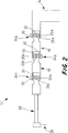
- FIG. 2 there is shown an electric position sensor 12.
- reference numeral 14 denotes a stationary support member of a fixed main body (not shown) of the cutting device 10.
- a first and a second arm member 16, 18 are connected to the support member 14 in series via a first and a second universal joint 24a, 24b.
- Each universal joint 24a, 24b has two pivot axes 20a and 22a, or 20b and 22b, perpendicular to each other.
- a handpiece 28 is connected to the second arm member 18 in series via a third universal joint 24c having two pivot axes 20c, 22c perpendicular to each other.
- a cutting element 26 is detachably attached to a free end of the handpiece 28.
- the cutting element 26 is freely movable or pivotable with respect to the six axes 20a, 22a, 20b, 22b, 20c, 22c.
- Fig. 2 shows the first and second arm members 16, 18 and handpiece 28 being extended completely.
- those members 16, 18, 28 will be pivoted about the individual universal joints 24a, 24b, 24c, so as to permit the handpiece 28 or cutting element 26 to freely be moved.
- the first and second arm members 16, 18 and handpiece 28 may resiliently be connected to each other, or to the support member 14 of the cutting device 10, as needed, so as to improve the operability of the handpiece 28.
- the six rotary encoders 30 produce six electric signals which cooperate with each other to represent the three-dimensional movement of the cutting element 26.
- the optical position sensor 12 further includes a stereoscopic image pick-up element such as a pair of coupled device (CCD) cameras 40a, 40b or PSD (positioning sensitive device) cameras spaced apart from each other.
- CCD coupled device
- PSD positioning sensitive device
- the CCD cameras 40a, 40b are fixed to, or supported by, a support frame (not shown) at those positions which permit the CCD cameras 40a, 40b to sufficiently cover the space in which the three point light sources 38a, 38b, 38c are moved around when the handpiece 32 is used for cutting the tooth.
- the electric or optical position sensor 12 shown in Fig. 2 or Fig. 3 detects the movement of not the cutting element 26, 34 but the handpiece 28, 32, the position signal supplied from the position sensor 12 is adjusted, as needed, depending on the configuration or external shape of the cutting element 26, 34 secured to the handpiece 28, 32.
- the position signal produced from the cutting-element position sensor 12 and stored in the storing device 42 is transferred to a control device 44 after the cavity preparation has been completed.
- the control device 44 controls operation of a machining device 46, so that the machining device 46 machines a prefabricated blank into a dental filling according to the position signal, which thus serves as machining information.
- an occlusal surface i.e., top surface
- the external shape of the tooth is detected and transformed into position data by utilizing the position sensor 12, specifically, tracing the external shape of the tooth with the cutting element 11.
- the position signal may be stored in the storing device 42, and further be used when the prefabricated material is machined into the dental filling, or when the dental filling is finished for the occlusion adjustment for fitting to the tooth cavity.
- the present production system provides a dental filling for restoration of a tooth crown, with much ease and in a short time.
- the operation of the present production system does not require great skill. Therefore, the present system easily produces a dental filling with high quality.
- FIG. 4 there is shown another embodiment according to the present invention, for producing a dental filling for restoration of a tooth crown.
- the same reference numerals as used in Fig. 1 are used for designating corresponding parts or elements of the instant embodiment, and the description of those parts or elements are omitted.
- the fitting member 48 includes, as shown in Fig. 5, a fitting portion 50 to be fitted on a tooth 49 such as a damaged tooth of a patient, and a rod portion 52 extending from the fitting portion 50. With the fitting portion 50 being fitted on the tooth 49, the rod portion 52 extends out of the mouth of the patient, so that the rod portion 52 is fixed relative to the stationary member of the cutting device 10.
- the instant production system detects, with high accuracy, a three-dimensional outline form of a cavity even in the even that the cavity is prepared over a long period of time.
- a dental filling is produced by a machining device 46 by using the accurate outline form of the cavity, the dental filling produced enjoys improved accuracy of the outline form thereof.
- the CCD cameras 58a, 58b are fixed to, or supported by, a stationary member (not shown) of the cutting device 10, at those positions which permit the CCD cameras 58a, 58b to sufficiently cover the space in which the light sources 60a, 60b, 60c are moved.
- the tooth position sensor 54 monitors the displacement of the tooth 55 by detecting the movement of the light sources 60a, 60b, 60c, and produces an electric signal.
- the electric signal provides a batch of displacement data representing the three-dimensional displacement of the tooth 55.
Abstract
Description
- The present invention generally relates to a process and an apparatus for producing a dental filling for restoration of a tooth crown, and particularly to the technique of producing such a dental filling with ease and with high form accuracy.
- As one of known dental restoration techniques of repairing or filling a damage of hard tissue of a tooth crown and thereby restoring the function of the tooth, there is the technique of preparing a cavity in the tooth crown by cutting and grinding the damaged hard tissue and then fitting to the cavity a solid, dental filling (e.g., inlay, onlay, core, crown, bridge) which has been produced to have an external shape or form corresponding to the cavity.
- A dental filling for restoration of a tooth crown is formed of metal, porcelain, composite resin, etc. In particular, metal and porcelain are preferable filling materials, because those materials have high strength and high abrasion resistance. Whichever material is selected, an impression (i.e., imprint of a tooth) is taken from a tooth in which a cavity has been prepared, and a model (i.e., replica of the tooth) is formed of, for example, plaster on the impression. This model is used for producing a dental filling to be fitted to the cavity, in a manner suitable for the selected material.
- More specifically, in the event that metal is selected as filling material, it is a common practice that a model is used for forming a wax pattern corresponding to a tooth including a cavity; the wax pattern is immersed in a fireproof investment such as plaster; the plaster is heated for removing or evaporating the wax pattern and thereby obtaining a mold; the mold is used for casting the metal; and the cast metal is cut, ground and polished into a final, dental filling. Meanwhile, in the event that porcelain is selected, it is common that a model is used for producing a secondary model; wet porcelain mix is applied to the cavity of the secondary model, and then they are fired; the fired porcelain is cut, ground and polished into a final dental filling.
- However, any of the known techniques in which various sorts of materials are used for producing a dental filling, essentially requires taking an impression of a tooth, forming a model on the impression, and producing a pattern or a secondary model using the model. Thus, those techniques are very cumbersome to carry out, need a long time, and high in cost.
- In addition, since, in the conventional dental filling production techniques, information representing the external shape or form of a tooth having a cavity, is transmitted to a final dental filling via a plurality of intermediates such as a model, pattern, or secondary model, dimensional errors accumulate because of deformation, shrinkage, and/or expansion of the materials of those intermediates. Thus, it has been very difficult to produce a dental filling with desired dimensional accuracy. Accordingly, a skillful technician is needed for the dental filling production. However, recently, dental technicians have been short in number, even posing a social problem.
- Furthermore, while attention has been directed to using porcelain as a filling material because of its excellent color tone and gloss, high corrosion resistance, and high mechanical strength, a satisfactory technique of producing a dental filling using porcelain has not been established yet. The reasons for that are as follows: It is very difficult to control firing of porcelain under high temperature and high pressure. Although porcelain shrinks, i.e., reduces in volume, several tens of percentage points due to the firing, it is very difficult to take into account, in advance, the amount of shrinkage of the porcelain, unlike industrial products. In addition, dental fillings are required to have different external forms corresponding to individual teeth. Thus, no conventional technique can provide a porcelain dental filling with desired qualities, in particular, mechanical strength, at low cost.
- In the above-described background, the present invention has been developed. It is therefore an object of the present invention to provide a process and an apparatus for producing a dental filling for restoration of a tooth crown, with ease and with high dimensional accuracy, thereby reducing to practice a high-quality, porcelain dental filling, for example, which has been difficult to produce by the conventional techniques.
- According to a first aspect of the present invention, there is provided a process of producing a dental filling for restoration of a tooth crown, the dental filling being fitted to a cavity prepared in the tooth for filling the cavity, comprising the steps of (1) monitoring, using a cutting-element position sensor, movement of a cutting element for preparing the cavity, and thereby producing a batch of outline form data representing a three-dimensional outline form of the cavity, and (2) machining a prefabricated filling blank according to the batch of outline form data, into the dental filling having an outline form identical with the outline form of the cavity.
- In the dental filling production process arranged as described above, the three-dimensional outline form of a cavity prepared in a tooth by cutting and grinding thereof, is transformed into a batch of outline form data, simultaneously with the preparation of the cavity. The batch of outline data is used directly for machining a prefabricated filling blank into a dental filling, so that the dental filling has an outline form identical with the outline form of the cavity. Thus, the present process does not require cumbersome steps such as taking an impression of a tooth or forming a model of the same. That is, the present process ensures that a desired dental filling is produced with ease and in a short time.
- In the present process, it is possible to produce a dental filling by machining a pre-cast or pre-fired filling material. Thus, it is not required to take into account the amount of deformation and/or shrinkage of the filling material due to, for example, firing thereof. Therefore, in the present process, some materials which have conventionally been difficult to use can be used, without difficulty, as a filling material. Thus, the present process provides dental fillings with higher qualities offered by those materials.
- According to a second aspect of the present invention, there is provided an apparatus for producing a dental filling for restoration of a tooth crown, the dental filling being fitted to a cavity prepared in the tooth for filling the cavity, comprising (a) cutting means for preparing the cavity, the cutting means including a cutting element for cutting the tooth for the cavity preparation, and a cutting-element position sensor means for monitoring movement of the cutting element for the cavity preparation and thereby producing a batch of outline form data representing a three-dimensional outline form of the cavity, (b) memory means for storing the batch of outline form data, (c) machining means for machining a prefabricated filling blank into the dental filling, and (d) control means for controlling operation of the machining means according to the batch of outline form data, so that the filling blank is machined into the dental filling having an outline form identical with the outline form of the cavity.
- In a preferred embodiment in accordance with the second aspect of the invention, the cutting means further includes an immobilizing means for immobilizing the tooth.
- In another embodiment in accordance with the second aspect of the invention, the cutting means further includes a tooth position sensor means for monitoring displacement of the tooth and thereby producing a batch of displacement data representing the displacement of the tooth, and an adjusting means for adjusting the batch of outline form data based on the batch of displacement data.
- Since the outline form of the cavity prepared in the tooth is more accurately detected by the cutting-element position sensor means because of employment of the immobilizing means, or of the tooth-position sensor means and adjusting means, the present apparatus is more advantageous for producing a dental filling with metal or porcelain which requires a strict similarity between the outline forms of the cavity and the filling.
- The above and optional objects, features and advantages of the present invention will be better understood by reading the following detailed description of the presently preferred embodiments of the invention when considered in conjunction with the accompanying drawings, in which:
- Fig. 1 is a diagrammatic view of a dental filling production system embodying the present invention;
- Fig. 2 is an illustrative view of a cutting-element position sensor employed in the system of Fig. 1;
- Fig. 3 is an illustrative view of another cutting-element position sensor employed in the system of Fig. 1;
- Fig. 4 is a diagrammatic view of another embodiment of the dental filling production system of the present invention;
- Fig. 5 is a perspective view of a tooth immobilizing device employed in the system of Fig. 4;
- Fig. 6 is a diagrammatic view of yet another embodiment of the dental filling production system of the present invention; and
- Fig. 7 is an illustrative view of a tooth-position sensor employed in the system of Fig. 6.
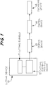
- Referring first to Fig. 1, there is shown a production system in accordance with the present invention, for producing a dental filling for restoration of a tooth crown. In the figure,
reference numeral 10 designates a dental cutting device which, as well known, includes a power drive such as an electric engine and acutting element 11 secured to a handpiece (28, Fig. 2) operatively connected to the power drive. Thecutting element 11 is rotated at high speed by the power drive, for cutting and grinding a tooth. Thecutting device 10 further includes a cutting-element position sensor 12 for detecting three-dimensional movement of thecutting element 11. When thecutting element 11 is moved for cutting the tooth and thereby preparing a cavity in the tooth crown, theposition sensor 12 monitors the movement of thecutting element 11, and produces a batch of outline form data representing a three-dimensional outline form of the cavity prepared. The present system utilizes the batch of outline form data for producing a dental filling to be fitted to the cavity prepared in the tooth crown. - The cutting-
element position sensor 12 employed in thecutting device 10 may be constituted by one of various sorts of sensors; such as an electric sensor, optical sensor, or magnetic sensor. Two examples of theposition sensor 12 are shown in Figs. 2 and 3, respectively. - First, in Fig. 2, there is shown an
electric position sensor 12. In the figure,reference numeral 14 denotes a stationary support member of a fixed main body (not shown) of thecutting device 10. A first and asecond arm member support member 14 in series via a first and a seconduniversal joint universal joint pivot axes handpiece 28 is connected to thesecond arm member 18 in series via a third universal joint 24c having twopivot axes cutting element 26 is detachably attached to a free end of thehandpiece 28. Since thehandpiece 28 is supported by thestationary support member 14 of thecutting device 10 via the threeuniversal joints cutting element 26 is freely movable or pivotable with respect to the sixaxes - Fig. 2 shows the first and
second arm members handpiece 28 being extended completely. When thecutting element 26 is actually operated, thosemembers universal joints handpiece 28 or cuttingelement 26 to freely be moved. The first andsecond arm members handpiece 28 may resiliently be connected to each other, or to thesupport member 14 of thecutting device 10, as needed, so as to improve the operability of thehandpiece 28. - The
electric position sensor 12 of Fig. 2 further includes arotary encoder 30 for each of the sixpivot axes universal joints rotary encoders 30 produces an electric signal, such as a pulse signal, representing an amount of rotation of a corresponding one of the sixpivot axes - When the
handpiece 28, or thecutting element 26 secured to thehandpiece 28, is moved for cutting the tooth, the sixrotary encoders 30 produce six electric signals which cooperate with each other to represent the three-dimensional movement of thecutting element 26. - Meanwhile, Fig. 3 shows an
optical position sensor 12 for detecting movement of acutting element 34. In the figure,reference numeral 32 designates a handpiece to which thecutting element 34 is secured. Thehandpiece 32 may flexibly be connected to a stationary member (e.g.,member 14 in Fig. 2) of the cuttingdevice 10 in the same manner as that shown in Fig. 2, or may be constituted as an independent member in which a small-size motor ("micromotor") is incorporated and which is structurally independent of the other elements. Thehandpiece 32 includes a shank and asupport bar 36 protruding from the shank. Thesupport bar 36 supports three pointlight sources 38a, 38b, 38c which are spaced apart from each other in a common plane. The pointlight sources 38a, 38b, 38c may be constituted by light emitting diodes (LED), or optical fibers. - The
optical position sensor 12 further includes a stereoscopic image pick-up element such as a pair of coupled device (CCD)cameras CCD cameras CCD cameras light sources 38a, 38b, 38c are moved around when thehandpiece 32 is used for cutting the tooth. - When the
handpiece 32, or the cuttingelement 34 secured to thehandpiece 32, is moved for cutting the tooth, the movement thereof is determined by detecting the movement of the three pointlight sources 38a, 38b, 38c through theCCD cameras - As shown in Fig. 1, the present production system further includes a storing
device 42 for storing the position signal supplied from the cutting-element position sensor 12. The position signal represents the three-dimensional movement of the cuttingelement 11 for preparing a cavity in a tooth crown by cutting and grinding thereof, and therefore serves as a batch of outline form data representing a three-dimensional outline form of the cavity prepared in the tooth crown. - Since, strictly, the electric or
optical position sensor 12 shown in Fig. 2 or Fig. 3 detects the movement of not the cuttingelement handpiece position sensor 12 is adjusted, as needed, depending on the configuration or external shape of the cuttingelement handpiece - The position signal produced from the cutting-
element position sensor 12 and stored in thestoring device 42 is transferred to acontrol device 44 after the cavity preparation has been completed. Thecontrol device 44 controls operation of amachining device 46, so that themachining device 46 machines a prefabricated blank into a dental filling according to the position signal, which thus serves as machining information. - More specifically, the
machining device 56 may be selected from various sorts of known machining apparatus such as grinding machine, electric discharge machine, laser beam machine, depending on the selected sort of material for the dental filling. Since the position signal provided by the cutting-element position sensor 12 is directly used by thecontrol device 44 for controlling the machining operation of themachining device 46, themachining device 46 machines the prefabricated filling blank into the dental filling, so that the dental filling machined has a three-dimensional outline form identical with that of the cavity prepared in the tooth crown. - It is possible to machine out an occlusal surface (i.e., top surface) of the dental filling by using an impression which has been taken from the occlusal surface of the tooth before the cavity is prepared. Alternatively, however, it is possible that, before the cavity preparation, the external shape of the tooth is detected and transformed into position data by utilizing the
position sensor 12, specifically, tracing the external shape of the tooth with the cuttingelement 11. The position signal may be stored in thestoring device 42, and further be used when the prefabricated material is machined into the dental filling, or when the dental filling is finished for the occlusion adjustment for fitting to the tooth cavity. - As emerges from the foregoing description, the present dental filling production system easily obtains information on the external shape of a dental filling to be fitted to a cavity prepared in a tooth crown, when the cavity is prepared. In addition, the production system directly uses the obtained information for machining a prefabricated filling material into the dental filling, so that the dental filling has an external shape identical with that of the cavity prepared in the tooth. Thus, the present production system produces the dental filling without needing cumbersome steps such as taking an impression or forming a model.
- The present production system provides a dental filling for restoration of a tooth crown, with much ease and in a short time. The operation of the present production system does not require great skill. Therefore, the present system easily produces a dental filling with high quality.
- In addition, since the present production system produces a dental filling by machining a prefabricated material (filling material) according to the stored data, the present system does not require cumbersome steps, such as casting or firing, which have conventionally been necessary for producing an individual dental filling. Furthermore, the present system is free from the problem of taking into account the shrinkage amount of a filling material due to firing thereof. Therefore, the present system is advantageously applicable to the production of a dental filling using some sorts of materials which have been difficult to use in the known techniques. Thus, the present system easily provides a dental filling with high quality offered by such a material.
- Referring next to Fig. 4, there is shown another embodiment according to the present invention, for producing a dental filling for restoration of a tooth crown. The same reference numerals as used in Fig. 1 are used for designating corresponding parts or elements of the instant embodiment, and the description of those parts or elements are omitted.
- The instant production system has a
cutting device 10 including a handpiece (not shown) to which acutting element 11 is detachably attached, and a cutting-element position sensor 12 for monitoring movement of the cuttingelement 11. The cuttingdevice 10 further includes afitting member 48 for immobilizing a tooth to be cut, relative to a stationary member (e.g.,member 14 in Fig. 2) of the cuttingdevice 10, so as to prevent the tooth from moving around. - More specifically, the
fitting member 48 includes, as shown in Fig. 5, afitting portion 50 to be fitted on atooth 49 such as a damaged tooth of a patient, and arod portion 52 extending from thefitting portion 50. With thefitting portion 50 being fitted on thetooth 49, therod portion 52 extends out of the mouth of the patient, so that therod portion 52 is fixed relative to the stationary member of the cuttingdevice 10. - The
fitting portion 50 of thefitting member 48 may be constituted and used such that an element having a configuration generally corresponding to a normal tooth configuration is fitted on side surfaces of thetooth 49 by fastening a thread fastener, or by using an appropriate adhesive. Alternatively, it is possible to take an impression of thetooth 49 and produce an element having a configuration corresponding to that of thetooth 49, so that the produced element is fitted on thetooth 49. Furthermore, thefitting portion 50 may be constituted for fitting on a plurality of teeth of the patient. - The instant dental filling production system prevents a tooth from displacing, when the tooth is cut to prepare a cavity in the tooth. Thus, the present system effectively prevents the cutting
element position sensor 12 from producing position signal including errors caused by the displacement of the tooth. - Therefore, the instant production system detects, with high accuracy, a three-dimensional outline form of a cavity even in the even that the cavity is prepared over a long period of time. In addition, since a dental filling is produced by a
machining device 46 by using the accurate outline form of the cavity, the dental filling produced enjoys improved accuracy of the outline form thereof. - The first embodiment of Fig. 1 which does not have an immobilizing member like the
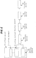
fitting member 48 of Fig. 5, is preferably used, for example, for producing a resin filling, or a center post of a core to be fitted in an internal cavity. The resin filling and the core's center post are not required to have high dimensional accuracy. Meanwhile, the second embodiment of Fig. 4 which has the immobilizingmember 48 is preferably used for producing a dental filling such as a metal or porcelain inlay that requires high dimensional accuracy. - Referring further to Fig. 6, there is shown a third embodiment in accordance with the present invention, for producing a dental filling for restoration of a tooth crown. The same reference numerals as used in Fig. 1 are used for designating corresponding parts or elements of the instant embodiment, and the description of those parts or elements are omitted.
- The present production system has a
cutting device 10 which includes a handpiece (not shown) to which acutting element 11 is detachably attached, and a cutting-element position sensor 12 for monitoring movement of the cuttingelement 11. The cuttingdevice 10 further includes atooth position sensor 54 for monitoring displacement of atooth 55 caused by motion of patient's body, while thetooth 55 is cut and ground by the cuttingelement 11. - More specifically, the
tooth position sensor 54 may be constituted by, for example, an optical sensor device as shown in Fig. 7. Theoptical sensor device 54 includes afitting member 56 to be fitted to thetooth 55 and three pointlight sources fitting member 56. The pointlight sources sensor device 54 further includes a stereoscopic image pick-up element in the form of a pair of charge-coupled device (CCD)cameras CCD cameras device 10, at those positions which permit theCCD cameras light sources tooth position sensor 54 monitors the displacement of thetooth 55 by detecting the movement of thelight sources tooth 55. - The
tooth position sensor 54 may be constituted by an electric sensor which includes a fitting member to be fitted to a tooth and a connection mechanism, as shown in Fig. 2, for connecting the fitting member to the stationary member of the cuttingdevice 10. In this case, the amount of displacement (i.e., rotation) with respect to each of the six axes of the connecting mechanism may be detected by a potentiometer associated with the each axis. Alternatively, thetooth position sensor 54 may be constituted by a magnetic sensor. - In the case where the
tooth position sensor 54 is not adapted to detect the relative position of thetooth 55 relative to the position of the cuttingelement 11 detected by the cutting-element position sensor 12, it is required to establish the positional relationship between the tooth 55 ( or fitting member 56) and the cuttingelement 11, for example by flexibly connecting the cuttingelement 11 to thefitting member 56 through a pin, groove, or hole. - The displacement signal produced by the
tooth position sensor 54, which signal is representative of the displacement of thetooth 55, is supplied to an adjustingdevice 62. The adjustingdevice 62 adjusts or corrects the position signal from the cutting-element position sensor 12, according to the displacement signal from thetooth position sensor 54, by removing from the position signal the errors caused by the displacement of thetooth 55. - Like the second embodiment of Fig. 4, the present production system detects with higher dimensional accuracy the three-dimensional outline form of the cavity prepared using the cutting
element 11, and thereby produces a dental filling to be fitted to the cavity, with improved form or shape accuracy. - In addition, the present system does not require that the
tooth 55 be immobilized when thetooth 55 is being cut and ground. Therefore, the cavity preparation is easily carried out, and the patient does not feel discomfort due to such immobility. - While the present invention has been described in its presently preferred embodiments, it is to be understood that the present invention is by no means limited to the details of those embodiments but may otherwise be embodied.
- For example, the construction or arrangement of the cutting-
element position sensor 12 ortooth position sensor 54 is not limited to the particulars of the illustrated embodiments. Specifically, one or more of the sixaxes handpiece 28 to thestationary member 14 of the cuttingdevice 10, shown in Fig. 2, may be replaced by one or more linearly movable elements. In this case, the amount of linear movement may be detected by a linear encoder. - Furthermore, the
optical position sensor - In the third embodiment of Fig. 6, the position signal corrected by the adjusting
device 62 is supplied to thestoring device 42. However, the production system may be adapted such that the storingdevice 42 stores both the position signal from the cutting-element position sensor 12 and the displacement signal from thetooth position sensor 54, and thecontrol device 44 adjusts the position signal based on the displacement signal. In this case, thecontrol device 44 serves as adjusting means. - It is to be understood that the present invention may be embodied with other changes, improvements and modifications that may occur to those skilled in the art without departing from the scope and spirit of the invention defined in the appended claims.
Claims (10)
- A process of producing a dental filling for restoration of a tooth crown, the dental filling being fitted to a cavity prepared in the tooth for filling the cavity, comprising the steps of:
monitoring, using a cutting-element position sensor (12), movement of a cutting element (11, 26, 34) for preparing said cavity, and thereby producing a batch of outline form data representing a three-dimensional outline form of said cavity, and
machining a prefabricated filling blank according to said batch of outline form data, into said dental filling having an outline form identical with the outline form of said cavity. - An apparatus for producing a dental filling for restoration of a tooth crown, the dental filling being fitted to a cavity prepared in the tooth for filling the cavity, comprising:
cutting means (10) for preparing said cavity,
said cutting means including a cutting element (11, 26, 34) for cutting the tooth for the cavity preparation, and a cutting-element position sensor means (12) for monitoring movement of said cutting element for said cavity preparation and thereby producing a batch of outline form data representing a three-dimensional outline form of said cavity;
memory means (42) for storing said batch of outline form data;
machining means (46) for machining a prefabricated filling blank into said dental filling; and
control means (44) for controlling operation of said machining means according to said batch of outline form data, so that said filling blank is machined into said dental filling having an outline form identical with the outline form of said cavity. - An apparatus according to claim 2, wherein said cutting means (10) further includes an immobilizing means (48) for immobilizing said tooth (49).
- An apparatus according to claim 2, wherein said cutting means (10) further includes:
a tooth position sensor means (54) for monitoring displacement of said tooth (55) and thereby producing a batch of displacement data representing the displacement of said tooth; and
an adjusting means (62) for adjusting said batch of outline form data based on said batch of displacement data. - An apparatus according to any one of claims 2, 3 or 4, wherein said cutting means (10) further includes:
a stationary support member (14);
at least one arm member (16, 18);
a handpiece (28) to which said cutting element (26) is attached; and
a plurality of universal joints (24a, 24b, 24c) connecting said stationary support member, said at least one arm member, and said handpiece in series, and thereby connecting said cutting element to said stationary support member. - An apparatus according to claim 5, wherein each of said universal joints (24a, 24b, 24c) has a pair of pivot axes (20a, 22a; 20b, 22b; 20c, 22c) perpendicular to each other; said cutting-element position sensor means (12) including a rotary encoder (30) associated with each of said pivot axes, for detecting a rotation amount of a corresponding one of said handpiece (28) and said at least one arm member (16, 18) about said each pivot axis, said rotary encoder generating an electric signal representing the detected rotation amount, the electric signals generated by the rotary encoders associated with the pivot axes of said universal joints cooperating with each other to provide said batch of outline form data.
- An apparatus according to any one of claims 2, 3 or 4, wherein said cutting means (10) further includes a handpiece (32) to which said cutting element (34) is attached,
said cutting-element position sensor means (12) including:
three point light sources (38a, 38b, 38c) which are supported by said handpiece such that the light sources are stationary relative to said cutting element; and
a stereoscopic image pick-up means (40a, 40b) for continuously taking a stereoscopic image of said three point light sources when the light sources are moved with said cutting element for said cavity preparation, said stereoscopic image continuously taken by said image pick-up means providing said batch of outline form data. - An apparatus according to claim 7, wherein said stereoscopic image pick-up means includes a pair of charge-coupled device cameras (40a, 40b).
- An apparatus according to claim 3, wherein said immobilizing means includes a fitting member (48) having a fitting portion (50) adapted to be fitted on said tooth, and a rod portion (52) extending from said fitting portion, said rod portion being stationary relative to a reference position.
- An apparatus according to claim 4, wherein said tooth position sensor means (54) includes:
a fitting member having a fitting portion (56) adapted to be fitted on said tooth, and a rod portion extending from said fitting portion;
three point light sources (60a, 60b, 60c) which are supported by said rod portion of said fitting member such that the light sources are stationary relative to said fitting portion; and
a stereoscopic image pick-up means (58a, 58b) for continuously taking a stereoscopic image of said three point light sources when the light sources are displaced with said tooth (55) during said cavity preparation, said stereoscopic image continuously taken by said image pick-up means providing said batch of displacement data.
Applications Claiming Priority (2)
| Application Number | Priority Date | Filing Date | Title |
|---|---|---|---|
| JP74033/91 | 1991-03-12 | ||
| JP7403391A JPH0747031B2 (en) | 1991-03-12 | 1991-03-12 | Equipment for preparing restorations for crown restoration |
Publications (3)
| Publication Number | Publication Date |
|---|---|
| EP0503890A2 true EP0503890A2 (en) | 1992-09-16 |
| EP0503890A3 EP0503890A3 (en) | 1993-10-27 |
| EP0503890B1 EP0503890B1 (en) | 1999-06-02 |
Family
ID=13535434
Family Applications (1)
| Application Number | Title | Priority Date | Filing Date |
|---|---|---|---|
| EP92302021A Expired - Lifetime EP0503890B1 (en) | 1991-03-12 | 1992-03-10 | Process and apparatus for producing dental filling for restoration of tooth crown |
Country Status (4)
| Country | Link |
|---|---|
| US (1) | US5163842A (en) |
| EP (1) | EP0503890B1 (en) |
| JP (1) | JPH0747031B2 (en) |
| DE (1) | DE69229291T2 (en) |
Cited By (2)
| Publication number | Priority date | Publication date | Assignee | Title |
|---|---|---|---|---|
| EP1133954A2 (en) * | 2000-03-15 | 2001-09-19 | Ivoclar Vivadent AG | Dental apparatus |
| WO2010010029A1 (en) * | 2008-07-22 | 2010-01-28 | Materialise Dental N.V. | Device for position and/or orientation control of dental tools or implants using dental drill guides |
Families Citing this family (94)
| Publication number | Priority date | Publication date | Assignee | Title |
|---|---|---|---|---|
| JPH0739553A (en) * | 1993-03-19 | 1995-02-10 | Egawa:Kk | Light source for measurement and measuring apparatus |
| US5607303A (en) * | 1994-08-03 | 1997-03-04 | Nakamura; Shoukou | Accessory apparatus of dentistry drills for putting oral cavity organs out of way |
| US5688118A (en) * | 1995-12-27 | 1997-11-18 | Denx Ltd. | Image sound and feeling simulation system for dentistry |
| DE19802751A1 (en) * | 1997-07-21 | 1999-01-28 | Sandhaus Sami Prof Dr Med Dr H | Guide for especially surgical instruments for implants in bone tissue |
| JP4543287B2 (en) * | 1997-11-15 | 2010-09-15 | 株式会社丸友 | Cleaning device |
| US7635390B1 (en) | 2000-01-14 | 2009-12-22 | Marctec, Llc | Joint replacement component having a modular articulating surface |
| US20040043355A1 (en) * | 2000-10-26 | 2004-03-04 | Egill Jonsson | Method and apparatus for tooth treatment |
| US7708741B1 (en) | 2001-08-28 | 2010-05-04 | Marctec, Llc | Method of preparing bones for knee replacement surgery |
| US20070084897A1 (en) | 2003-05-20 | 2007-04-19 | Shelton Frederick E Iv | Articulating surgical stapling instrument incorporating a two-piece e-beam firing mechanism |
| US9060770B2 (en) | 2003-05-20 | 2015-06-23 | Ethicon Endo-Surgery, Inc. | Robotically-driven surgical instrument with E-beam driver |
| US11896225B2 (en) | 2004-07-28 | 2024-02-13 | Cilag Gmbh International | Staple cartridge comprising a pan |
| US10159482B2 (en) | 2005-08-31 | 2018-12-25 | Ethicon Llc | Fastener cartridge assembly comprising a fixed anvil and different staple heights |
| US11246590B2 (en) | 2005-08-31 | 2022-02-15 | Cilag Gmbh International | Staple cartridge including staple drivers having different unfired heights |
| US7669746B2 (en) | 2005-08-31 | 2010-03-02 | Ethicon Endo-Surgery, Inc. | Staple cartridges for forming staples having differing formed staple heights |
| US8186555B2 (en) | 2006-01-31 | 2012-05-29 | Ethicon Endo-Surgery, Inc. | Motor-driven surgical cutting and fastening instrument with mechanical closure system |
| US8708213B2 (en) | 2006-01-31 | 2014-04-29 | Ethicon Endo-Surgery, Inc. | Surgical instrument having a feedback system |
| US7845537B2 (en) | 2006-01-31 | 2010-12-07 | Ethicon Endo-Surgery, Inc. | Surgical instrument having recording capabilities |
| US11793518B2 (en) | 2006-01-31 | 2023-10-24 | Cilag Gmbh International | Powered surgical instruments with firing system lockout arrangements |
| US8684253B2 (en) | 2007-01-10 | 2014-04-01 | Ethicon Endo-Surgery, Inc. | Surgical instrument with wireless communication between a control unit of a robotic system and remote sensor |
| US8701958B2 (en) | 2007-01-11 | 2014-04-22 | Ethicon Endo-Surgery, Inc. | Curved end effector for a surgical stapling device |
| US8931682B2 (en) | 2007-06-04 | 2015-01-13 | Ethicon Endo-Surgery, Inc. | Robotically-controlled shaft based rotary drive systems for surgical instruments |
| US11672531B2 (en) | 2007-06-04 | 2023-06-13 | Cilag Gmbh International | Rotary drive systems for surgical instruments |
| US11849941B2 (en) | 2007-06-29 | 2023-12-26 | Cilag Gmbh International | Staple cartridge having staple cavities extending at a transverse angle relative to a longitudinal cartridge axis |
| BRPI0901282A2 (en) | 2008-02-14 | 2009-11-17 | Ethicon Endo Surgery Inc | surgical cutting and fixation instrument with rf electrodes |
| US9005230B2 (en) | 2008-09-23 | 2015-04-14 | Ethicon Endo-Surgery, Inc. | Motorized surgical instrument |
| US9386983B2 (en) | 2008-09-23 | 2016-07-12 | Ethicon Endo-Surgery, Llc | Robotically-controlled motorized surgical instrument |
| US8608045B2 (en) | 2008-10-10 | 2013-12-17 | Ethicon Endo-Sugery, Inc. | Powered surgical cutting and stapling apparatus with manually retractable firing system |
| US9039414B2 (en) * | 2009-02-06 | 2015-05-26 | Scott E. Bulloch | Drill guide pin, shank, cannulated drill bit, and driver for creating a hole in a bone |
| US20100203479A1 (en) * | 2009-02-06 | 2010-08-12 | Bulloch Scott E | Dental implant system and methods |
| US11925354B2 (en) | 2010-09-30 | 2024-03-12 | Cilag Gmbh International | Staple cartridge comprising staples positioned within a compressible portion thereof |
| US9386988B2 (en) | 2010-09-30 | 2016-07-12 | Ethicon End-Surgery, LLC | Retainer assembly including a tissue thickness compensator |
| US9629814B2 (en) | 2010-09-30 | 2017-04-25 | Ethicon Endo-Surgery, Llc | Tissue thickness compensator configured to redistribute compressive forces |
| US10945731B2 (en) | 2010-09-30 | 2021-03-16 | Ethicon Llc | Tissue thickness compensator comprising controlled release and expansion |
| US9700317B2 (en) | 2010-09-30 | 2017-07-11 | Ethicon Endo-Surgery, Llc | Fastener cartridge comprising a releasable tissue thickness compensator |
| US11812965B2 (en) | 2010-09-30 | 2023-11-14 | Cilag Gmbh International | Layer of material for a surgical end effector |
| AU2012250197B2 (en) | 2011-04-29 | 2017-08-10 | Ethicon Endo-Surgery, Inc. | Staple cartridge comprising staples positioned within a compressible portion thereof |
| JP6305979B2 (en) | 2012-03-28 | 2018-04-04 | エシコン・エンド−サージェリィ・インコーポレイテッドEthicon Endo−Surgery,Inc. | Tissue thickness compensator with multiple layers |
| BR112014024098B1 (en) | 2012-03-28 | 2021-05-25 | Ethicon Endo-Surgery, Inc. | staple cartridge |
| US9289256B2 (en) | 2012-06-28 | 2016-03-22 | Ethicon Endo-Surgery, Llc | Surgical end effectors having angled tissue-contacting surfaces |
| US20140001231A1 (en) | 2012-06-28 | 2014-01-02 | Ethicon Endo-Surgery, Inc. | Firing system lockout arrangements for surgical instruments |
| US20150297222A1 (en) | 2014-04-16 | 2015-10-22 | Ethicon Endo-Surgery, Inc. | Fastener cartridges including extensions having different configurations |
| JP6532889B2 (en) | 2014-04-16 | 2019-06-19 | エシコン エルエルシーEthicon LLC | Fastener cartridge assembly and staple holder cover arrangement |
| CN106456176B (en) | 2014-04-16 | 2019-06-28 | 伊西康内外科有限责任公司 | Fastener cartridge including the extension with various configuration |
| BR112017004361B1 (en) | 2014-09-05 | 2023-04-11 | Ethicon Llc | ELECTRONIC SYSTEM FOR A SURGICAL INSTRUMENT |
| US9924944B2 (en) | 2014-10-16 | 2018-03-27 | Ethicon Llc | Staple cartridge comprising an adjunct material |
| US11154301B2 (en) | 2015-02-27 | 2021-10-26 | Cilag Gmbh International | Modular stapling assembly |
| US10441279B2 (en) | 2015-03-06 | 2019-10-15 | Ethicon Llc | Multiple level thresholds to modify operation of powered surgical instruments |
| US10390825B2 (en) | 2015-03-31 | 2019-08-27 | Ethicon Llc | Surgical instrument with progressive rotary drive systems |
| US10105139B2 (en) | 2015-09-23 | 2018-10-23 | Ethicon Llc | Surgical stapler having downstream current-based motor control |
| US11890015B2 (en) | 2015-09-30 | 2024-02-06 | Cilag Gmbh International | Compressible adjunct with crossing spacer fibers |
| US10285699B2 (en) | 2015-09-30 | 2019-05-14 | Ethicon Llc | Compressible adjunct |
| US10292704B2 (en) | 2015-12-30 | 2019-05-21 | Ethicon Llc | Mechanisms for compensating for battery pack failure in powered surgical instruments |
| US11213293B2 (en) | 2016-02-09 | 2022-01-04 | Cilag Gmbh International | Articulatable surgical instruments with single articulation link arrangements |
| US10448948B2 (en) | 2016-02-12 | 2019-10-22 | Ethicon Llc | Mechanisms for compensating for drivetrain failure in powered surgical instruments |
| US10357247B2 (en) | 2016-04-15 | 2019-07-23 | Ethicon Llc | Surgical instrument with multiple program responses during a firing motion |
| US20170296173A1 (en) | 2016-04-18 | 2017-10-19 | Ethicon Endo-Surgery, Llc | Method for operating a surgical instrument |
| JP7010956B2 (en) | 2016-12-21 | 2022-01-26 | エシコン エルエルシー | How to staple tissue |
| US20180168625A1 (en) | 2016-12-21 | 2018-06-21 | Ethicon Endo-Surgery, Llc | Surgical stapling instruments with smart staple cartridges |
| US10307170B2 (en) | 2017-06-20 | 2019-06-04 | Ethicon Llc | Method for closed loop control of motor velocity of a surgical stapling and cutting instrument |
| US10779820B2 (en) | 2017-06-20 | 2020-09-22 | Ethicon Llc | Systems and methods for controlling motor speed according to user input for a surgical instrument |
| USD906355S1 (en) | 2017-06-28 | 2020-12-29 | Ethicon Llc | Display screen or portion thereof with a graphical user interface for a surgical instrument |
| US10932772B2 (en) | 2017-06-29 | 2021-03-02 | Ethicon Llc | Methods for closed loop velocity control for robotic surgical instrument |
| US10779826B2 (en) | 2017-12-15 | 2020-09-22 | Ethicon Llc | Methods of operating surgical end effectors |
| US11179151B2 (en) | 2017-12-21 | 2021-11-23 | Cilag Gmbh International | Surgical instrument comprising a display |
| US11903581B2 (en) | 2019-04-30 | 2024-02-20 | Cilag Gmbh International | Methods for stapling tissue using a surgical instrument |
| US11771419B2 (en) | 2019-06-28 | 2023-10-03 | Cilag Gmbh International | Packaging for a replaceable component of a surgical stapling system |
| US11229437B2 (en) | 2019-06-28 | 2022-01-25 | Cilag Gmbh International | Method for authenticating the compatibility of a staple cartridge with a surgical instrument |
| US11779330B2 (en) | 2020-10-29 | 2023-10-10 | Cilag Gmbh International | Surgical instrument comprising a jaw alignment system |
| USD1013170S1 (en) | 2020-10-29 | 2024-01-30 | Cilag Gmbh International | Surgical instrument assembly |
| US11931025B2 (en) | 2020-10-29 | 2024-03-19 | Cilag Gmbh International | Surgical instrument comprising a releasable closure drive lock |
| US11896217B2 (en) | 2020-10-29 | 2024-02-13 | Cilag Gmbh International | Surgical instrument comprising an articulation lock |
| US11944296B2 (en) | 2020-12-02 | 2024-04-02 | Cilag Gmbh International | Powered surgical instruments with external connectors |
| US11737751B2 (en) | 2020-12-02 | 2023-08-29 | Cilag Gmbh International | Devices and methods of managing energy dissipated within sterile barriers of surgical instrument housings |
| US11744581B2 (en) | 2020-12-02 | 2023-09-05 | Cilag Gmbh International | Powered surgical instruments with multi-phase tissue treatment |
| US11849943B2 (en) | 2020-12-02 | 2023-12-26 | Cilag Gmbh International | Surgical instrument with cartridge release mechanisms |
| US11730473B2 (en) | 2021-02-26 | 2023-08-22 | Cilag Gmbh International | Monitoring of manufacturing life-cycle |
| US11749877B2 (en) | 2021-02-26 | 2023-09-05 | Cilag Gmbh International | Stapling instrument comprising a signal antenna |
| US11751869B2 (en) | 2021-02-26 | 2023-09-12 | Cilag Gmbh International | Monitoring of multiple sensors over time to detect moving characteristics of tissue |
| US11812964B2 (en) | 2021-02-26 | 2023-11-14 | Cilag Gmbh International | Staple cartridge comprising a power management circuit |
| US11744583B2 (en) | 2021-02-26 | 2023-09-05 | Cilag Gmbh International | Distal communication array to tune frequency of RF systems |
| US11723657B2 (en) | 2021-02-26 | 2023-08-15 | Cilag Gmbh International | Adjustable communication based on available bandwidth and power capacity |
| US11717291B2 (en) | 2021-03-22 | 2023-08-08 | Cilag Gmbh International | Staple cartridge comprising staples configured to apply different tissue compression |
| US11826012B2 (en) | 2021-03-22 | 2023-11-28 | Cilag Gmbh International | Stapling instrument comprising a pulsed motor-driven firing rack |
| US11806011B2 (en) | 2021-03-22 | 2023-11-07 | Cilag Gmbh International | Stapling instrument comprising tissue compression systems |
| US11759202B2 (en) | 2021-03-22 | 2023-09-19 | Cilag Gmbh International | Staple cartridge comprising an implantable layer |
| US11723658B2 (en) | 2021-03-22 | 2023-08-15 | Cilag Gmbh International | Staple cartridge comprising a firing lockout |
| US11826042B2 (en) | 2021-03-22 | 2023-11-28 | Cilag Gmbh International | Surgical instrument comprising a firing drive including a selectable leverage mechanism |
| US11737749B2 (en) | 2021-03-22 | 2023-08-29 | Cilag Gmbh International | Surgical stapling instrument comprising a retraction system |
| US11849945B2 (en) | 2021-03-24 | 2023-12-26 | Cilag Gmbh International | Rotary-driven surgical stapling assembly comprising eccentrically driven firing member |
| US11744603B2 (en) * | 2021-03-24 | 2023-09-05 | Cilag Gmbh International | Multi-axis pivot joints for surgical instruments and methods for manufacturing same |
| US11896219B2 (en) | 2021-03-24 | 2024-02-13 | Cilag Gmbh International | Mating features between drivers and underside of a cartridge deck |
| US11896218B2 (en) | 2021-03-24 | 2024-02-13 | Cilag Gmbh International | Method of using a powered stapling device |
| US20220378426A1 (en) | 2021-05-28 | 2022-12-01 | Cilag Gmbh International | Stapling instrument comprising a mounted shaft orientation sensor |
| US11937816B2 (en) | 2021-10-28 | 2024-03-26 | Cilag Gmbh International | Electrical lead arrangements for surgical instruments |
Citations (2)
| Publication number | Priority date | Publication date | Assignee | Title |
|---|---|---|---|---|
| US3861044A (en) * | 1972-05-04 | 1975-01-21 | Jr William E Swinson | Dental fitting process |
| EP0086167A2 (en) * | 1982-02-05 | 1983-08-17 | Luc Barrut | Method of and device for forming or treating teeth or dental prostheses |
Family Cites Families (11)
| Publication number | Priority date | Publication date | Assignee | Title |
|---|---|---|---|---|
| US3218624A (en) * | 1963-03-25 | 1965-11-16 | Ronald S O Zane | Attitude deviation indicating device |
| US4182312A (en) * | 1977-05-20 | 1980-01-08 | Mushabac David R | Dental probe |
| DE3003435A1 (en) * | 1980-01-31 | 1981-08-06 | Becker Dental-Labor Gmbh, 5100 Aachen | METHOD AND DEVICE FOR PRODUCING A CROWN PART |
| US4575805A (en) * | 1980-12-24 | 1986-03-11 | Moermann Werner H | Method and apparatus for the fabrication of custom-shaped implants |
| JPS57200144A (en) * | 1981-06-03 | 1982-12-08 | Hitachi Ltd | Automatic production of denture |
| FR2536654B1 (en) * | 1982-11-30 | 1987-01-09 | Duret Francois | METHOD FOR PRODUCING A DENTAL PROSTHESIS |
| CH672722A5 (en) * | 1986-06-24 | 1989-12-29 | Marco Brandestini | |
| NL8702391A (en) * | 1987-10-07 | 1989-05-01 | Elephant Edelmetaal Bv | METHOD FOR MANUFACTURING A DENTAL CROWN FOR A TEETH PREPARATION USING A CAD-CAM SYSTEM |
| US4941826A (en) * | 1988-06-09 | 1990-07-17 | William Loran | Apparatus for indirect dental machining |
| JPH0252964A (en) * | 1988-08-15 | 1990-02-22 | Mitsubishi Electric Corp | Multiroom type refrigerating circuit |
| US5017139A (en) * | 1990-07-05 | 1991-05-21 | Mushabac David R | Mechanical support for hand-held dental/medical instrument |
-
1991
- 1991-03-12 JP JP7403391A patent/JPH0747031B2/en not_active Expired - Lifetime
-
1992
- 1992-03-06 US US07/846,711 patent/US5163842A/en not_active Expired - Fee Related
- 1992-03-10 EP EP92302021A patent/EP0503890B1/en not_active Expired - Lifetime
- 1992-03-10 DE DE69229291T patent/DE69229291T2/en not_active Expired - Fee Related
Patent Citations (2)
| Publication number | Priority date | Publication date | Assignee | Title |
|---|---|---|---|---|
| US3861044A (en) * | 1972-05-04 | 1975-01-21 | Jr William E Swinson | Dental fitting process |
| EP0086167A2 (en) * | 1982-02-05 | 1983-08-17 | Luc Barrut | Method of and device for forming or treating teeth or dental prostheses |
Cited By (3)
| Publication number | Priority date | Publication date | Assignee | Title |
|---|---|---|---|---|
| EP1133954A2 (en) * | 2000-03-15 | 2001-09-19 | Ivoclar Vivadent AG | Dental apparatus |
| EP1133954A3 (en) * | 2000-03-15 | 2003-01-29 | Ivoclar Vivadent AG | Dental apparatus |
| WO2010010029A1 (en) * | 2008-07-22 | 2010-01-28 | Materialise Dental N.V. | Device for position and/or orientation control of dental tools or implants using dental drill guides |
Also Published As
| Publication number | Publication date |
|---|---|
| JPH0747031B2 (en) | 1995-05-24 |
| DE69229291T2 (en) | 1999-11-18 |
| DE69229291D1 (en) | 1999-07-08 |
| US5163842A (en) | 1992-11-17 |
| EP0503890A3 (en) | 1993-10-27 |
| EP0503890B1 (en) | 1999-06-02 |
| JPH04282151A (en) | 1992-10-07 |
Similar Documents
| Publication | Publication Date | Title |
|---|---|---|
| US5163842A (en) | Process and apparatus for producing dental filling for restoration of tooth crown | |
| US6287121B1 (en) | Material for a dental prosthesis, method and device for determining the shape of a remaining tooth area to be provided with a dental prosthesis, method and arrangement for producing a dental prosthesis and use of the arrangement | |
| KR100712771B1 (en) | A process for production of a synthetic tooth substitute | |
| US5813859A (en) | Method and apparatus for tooth restoration | |
| US4575805A (en) | Method and apparatus for the fabrication of custom-shaped implants | |
| US6568936B2 (en) | Method and apparatus for preparing dental restorations | |
| KR100760073B1 (en) | Machine tool for the production of base structures for false teeth | |
| EP1652489B1 (en) | Production method of three-dimensional shape data of dental prosthesis | |
| US5224049A (en) | Method, system and mold assembly for use in preparing a dental prosthesis | |
| KR101567204B1 (en) | Method and system for fabricating dental prosthesis | |
| US7234938B2 (en) | Milling/grinding machine for the manufacture of dental-medical workpieces | |
| KR100678362B1 (en) | Production of replacement teeth from a three-dimensionally determined and digitised positive model | |
| KR101340971B1 (en) | Method and apparatus for obtaining data for a dental component and a physical dental model | |
| CA2449509C (en) | Method and device for the three-dimensional mapping and digitization of a plaster or positive model | |
| WO1991015163A1 (en) | Computerized dental system and related instrumentation and methods | |
| WO1998032394A1 (en) | Dental scanning method and apparatus | |
| US20150289954A1 (en) | Computer fabrication of dental prosthetics | |
| US7835558B2 (en) | Method and system for making dental restorations | |
| JP2002523133A (en) | Method of manufacturing dentures by computer control | |
| US20100316972A1 (en) | Method for the generative production of individual dental preformed parts for articulators | |
| EP3875054A1 (en) | Digital three-dimensional tooth model system | |
| CN1917827A (en) | Method of manufacturing a dental part | |
| AU2001236999B2 (en) | Apparatus and method for producing a dental prosthetic with a device having a linear rotary bearing | |
| AU2001236999A1 (en) | Apparatus and Method for Producing a Dental Prosthetic with a Device Having a Linear Rotary Bearing | |
| US20030003420A1 (en) | Process for producing a dental prosthesis |
Legal Events
| Date | Code | Title | Description |
|---|---|---|---|
| PUAI | Public reference made under article 153(3) epc to a published international application that has entered the european phase |
Free format text: ORIGINAL CODE: 0009012 |
|
| 17P | Request for examination filed |
Effective date: 19920422 |
|
| AK | Designated contracting states |
Kind code of ref document: A2 Designated state(s): CH DE FR LI |
|
| PUAL | Search report despatched |
Free format text: ORIGINAL CODE: 0009013 |
|
| AK | Designated contracting states |
Kind code of ref document: A3 Designated state(s): CH DE FR LI |
|
| 17Q | First examination report despatched |
Effective date: 19950919 |
|
| GRAG | Despatch of communication of intention to grant |
Free format text: ORIGINAL CODE: EPIDOS AGRA |
|
| GRAG | Despatch of communication of intention to grant |
Free format text: ORIGINAL CODE: EPIDOS AGRA |
|
| GRAH | Despatch of communication of intention to grant a patent |
Free format text: ORIGINAL CODE: EPIDOS IGRA |
|
| RBV | Designated contracting states (corrected) |
Designated state(s): CH DE LI |
|
| GRAH | Despatch of communication of intention to grant a patent |
Free format text: ORIGINAL CODE: EPIDOS IGRA |
|
| GRAA | (expected) grant |
Free format text: ORIGINAL CODE: 0009210 |
|
| AK | Designated contracting states |
Kind code of ref document: B1 Designated state(s): CH DE LI |
|
| REG | Reference to a national code |
Ref country code: CH Ref legal event code: EP |
|
| REF | Corresponds to: |
Ref document number: 69229291 Country of ref document: DE Date of ref document: 19990708 |
|
| PLBE | No opposition filed within time limit |
Free format text: ORIGINAL CODE: 0009261 |
|
| STAA | Information on the status of an ep patent application or granted ep patent |
Free format text: STATUS: NO OPPOSITION FILED WITHIN TIME LIMIT |
|
| 26N | No opposition filed | ||
| PGFP | Annual fee paid to national office [announced via postgrant information from national office to epo] |
Ref country code: DE Payment date: 20010319 Year of fee payment: 10 |
|
| PGFP | Annual fee paid to national office [announced via postgrant information from national office to epo] |
Ref country code: CH Payment date: 20010320 Year of fee payment: 10 |
|
| PG25 | Lapsed in a contracting state [announced via postgrant information from national office to epo] |
Ref country code: LI Free format text: LAPSE BECAUSE OF NON-PAYMENT OF DUE FEES Effective date: 20020331 Ref country code: CH Free format text: LAPSE BECAUSE OF NON-PAYMENT OF DUE FEES Effective date: 20020331 |
|
| PG25 | Lapsed in a contracting state [announced via postgrant information from national office to epo] |
Ref country code: DE Free format text: LAPSE BECAUSE OF NON-PAYMENT OF DUE FEES Effective date: 20021001 |
|
| REG | Reference to a national code |
Ref country code: CH Ref legal event code: PL |