EP0504446B1 - Coded information reading system - Google Patents
Coded information reading system Download PDFInfo
- Publication number
- EP0504446B1 EP0504446B1 EP91104211A EP91104211A EP0504446B1 EP 0504446 B1 EP0504446 B1 EP 0504446B1 EP 91104211 A EP91104211 A EP 91104211A EP 91104211 A EP91104211 A EP 91104211A EP 0504446 B1 EP0504446 B1 EP 0504446B1
- Authority
- EP
- European Patent Office
- Prior art keywords
- pattern
- signal
- coded
- reading system
- information reading
- Prior art date
- Legal status (The legal status is an assumption and is not a legal conclusion. Google has not performed a legal analysis and makes no representation as to the accuracy of the status listed.)
- Expired - Lifetime
Links
Images

Classifications
-
- G—PHYSICS
- G06—COMPUTING; CALCULATING OR COUNTING
- G06K—GRAPHICAL DATA READING; PRESENTATION OF DATA; RECORD CARRIERS; HANDLING RECORD CARRIERS
- G06K7/00—Methods or arrangements for sensing record carriers, e.g. for reading patterns
- G06K7/08—Methods or arrangements for sensing record carriers, e.g. for reading patterns by means detecting the change of an electrostatic or magnetic field, e.g. by detecting change of capacitance between electrodes
- G06K7/082—Methods or arrangements for sensing record carriers, e.g. for reading patterns by means detecting the change of an electrostatic or magnetic field, e.g. by detecting change of capacitance between electrodes using inductive or magnetic sensors
- G06K7/087—Methods or arrangements for sensing record carriers, e.g. for reading patterns by means detecting the change of an electrostatic or magnetic field, e.g. by detecting change of capacitance between electrodes using inductive or magnetic sensors flux-sensitive, e.g. magnetic, detectors
Definitions
- This invention relates to a system for reading coded information which is expressed by a pattern such as a bar code pattern and, more particularly, to an improvement of a reading system of a type in which a pattern is formed with magnetically different materials and this pattern is read by an electromagnetic sensor.
- a coded pattern reading method according to which a black and white bar code pattern in which light reflection property varies depending upon the black and white portions is read in an optical manner.
- the optical type coded pattern reading method has the disadvantage that, when reflection and permeation of light are hindered due to depostion of dust on the black and white pattern section or the reading unit, it becomes extremely difficult to detect the pattern.
- the prior art optical type bar code system can be applied only to a case where an article on which a pattern should be provided is made of a material such as paper on which the pattern can be printed or an article on which a printed pattern paper can be bonded semi-fixedly so that it will not come off easily. It is difficult to apply this optical type bar code system to other articles. If, for example, one attempts to apply the optical type bar code system to a case where a manufacturing number should be affixed in the form of a pattern to an article made of metal such as cast iron, he will not be able to print an optical type bar code pattern on the cast iron itself. Bonding of a pattern printed paper on the cast iron article will not work because it will easily come off from such cast iron article and/or become soiled.
- U.S. Patent No. 4,883,949 proposes a magnetic type coded data reading device according to which a patterned code representation magnetic sheet is bonded to an article and coded information on the code representation magnetic sheet is read by means of a magnetic sensor employing a mutual induction coil comprising a primary coil which is excited by ac and a secondary coil which thereby generates a mutual induction voltage.
- coded information can be read magnetically even when it cannot be read optically because the pattern surface is soiled with dust.
- the code representation magnetic sheet which is prepared separately must be attached to the article semi-fixedly to prevent ready coming off of the sheet from the article as in the case of the optical type reading device; however, there still remains the likelihood of coming off of the magnetic sheet.
- This prior art coded data reading device identifies coded information by operating an amplitude value of mutual induction voltage produced in the secondary coil of the magnetic sensor by a microcomputer or the like computing device, utilizing the phenomenon that the amplitude level of mutual induction voltage produced in the secondary coil of the mutual induction coil varies with the width, thickness and interval of a metal portion of the code representation magnetic sheet. Since, however, the amplitude value of mutual induction voltage produced in the secondary coil varies also with the distance (gap) between the code representation magnetic sheet and the mutual induction coil, a protection film is normally provided on the surface of the magnetic sheet which constitutes a guide surface for the mutual induction coil to provide a flat surface with a view to maintaining the distance constant during reading of the coded information.
- an object of the invention to provide a coded information reading system capable of reading coded information accurately without being adversely affected by change in the amplitude level of an induced output signal due to the state of use or environmental change.
- the coded information reading system comprises pattern recording means having a pattern formed by first and second materials of mutually different magnetic characters in an arrangement corresponding to desired coded information; sensor means including coil means excited by a reference ac signal for producing an induced output signal, said induced output signal exhibiting electrical phases corresponding to existence of the first and second materials in the pattern when said coil means has approached the pattern; and signal forming means for measuring the electrical phases of the induced output signal from said coil means and forming, in correspondence to measured data of the electrical phases, a pattern reading signal corresponding to the first and second materials.
- the induced output signal from the coil means exhibits change corresponding to existence of the first and second materials in the pattern when the coil means has approached the pattern.
- This change includes change in the electrical phase.
- the coil means preferably include plural primary coils which are excited by plural reference ac signals which are different in phase from each other.
- the change is not so remarkable as in the case where the primary coils are excited by plural reference ac signals, change in the electrical phase can be recognized also in a case where the primary coil is excited by a single reference ac signal.
- the signal forming means is provided and the electrical phase of the induced output signal is measured by this signal forming means.
- a pattern reading signal corresponding to the first and second materials is formed.
- the pattern reading signal thus obtained is a signal corresponding to existence of the first and second materials constituting the pattern, e.g., a square pulse signal corresponding to existence of the first and second materials.
- the electrical phase of the induced output signal changes only in accordance with existence of the first and second materials in the pattern and is not affected by variation in the distance between the sensor means and the pattern unless the sensor means is inclined to the pattern surface, nor is the electrical phase affected by the environmental change such as change in the ambient temperature. Accordingly, coded information can be read accurately regardless of the state of use and the environmental change such as in a case where the pattern surface has become uneven due to unintended depositon of paint or the like.
- the coil means may include two primary coils which are excited by two reference ac signals which are different in phase from each other.
- the respective primary coils may be spaced from each other so that, when one of the primary coils approaches the pattern, the other primary coil cannot approach the pattern.
- the amplitude level of a first induced signal which is induced by the primary coil which approaches the pattern exhibits change corresponding to the pattern and the amplitude level of a second induced signal which is induced by the other primary coil does not exhibit change corresponding to the pattern. Since the exciting signals are different in phase, the first induced signal and the second induced signal are different in phase form each other.
- an induced output signal which is a composite signal of the first and second induced signals changes in its electrical phase in accordance with the change in the amplitude level of the first induced signal and, consequently, it exhibits an electrical phase corresponding to the first and second materials in the pattern (i.e., phase difference relative to the reference ac signal).
- the pattern recording means may include not only a first pattern formed by first and second materials which are magnetically different from each other in an arrangement corresponding to desired coded information but also a second pattern formed by two magnetically different materials and arranged with opposite characteristics to the first pattern.
- the coil means may include two primary coils whch are excited by two reference ac signals which are different in phase from each other. These primary coils may be suitably spaced from each other so that, when one of the primary coils approaches the first pattern, the other primary coil approaches the second pattern.
- the amplitude level of a first induced signal induced by the primary coil which approaches the first pattern exhibits a change corresponding to the pattern and the amplitude level of a second induced signal induced by the primary coil which approaches the second pattern exhibits a change which is of opposite characteristics corresponding to the second pattern. Since the phase of respective exciting signals is different, the first and second induced signals are different in the electrical phase.
- an induced output signal which is a composite signal of the first and second induced signals changes in its electrical phase to a larger degree in accordance with a differential change in the amplitude levels of the first and second induced signals and, consequently, it exhibits a larger electrical phase (phase difference relative to the reference ac signal) corresponding to existence of the first and second materials in the pattern.
- the accuracy in measurement of electrical phase therefore is improved with resulting improvement in accuracy in reading of the pattern.
- the two materials which constitute the second pattern may have opposite magnetic characteristics to the first and second materials which constitute the first pattern. For example, if permeability of the first material is larger than that of the second material, permeability of the third material in the second pattern which corresponds to the first material should be smaller than that of the fourth material which corresponds to the second material.
- the third and fourth materials the same materials as the first and second materials may be employed.
- the second pattern can be formed by arranging the first and second materials in opposite relation to the first pattern.
- any material may be used as the first and second materials which constitute the pattern so long as they are magnetically different from each other.
- permeability of one of the first and second materials may be larger than that of the other material. In that case, difference in reluctance is produced in accordance with difference in permeability.
- conductivity of one of the first and second materials may be larger than that of the other material. In that case, difference in the manner of generation of an eddy current is produced in accordance with difference in conductivity and difference in reluctance is thereby produced.
- a pattern may be formed by combining permeability and conductivity. Difference in the magnetic property may be produced by differring the manner of magnetization.
- One or both of the first and second materials may be the same as the material of a base portion of the pattern recording means.
- the base portion of the pattern recording means is made of a magnetic substance such as iron
- permeability of the material can be changed by subjecting the base portion to a partial hardening by means of laser beam, so that this hardening method may be adopted.
- a pattern may be formed by forming a projection and a depression on the surface of the magnetic substance.
- the first material is formed by the projection of the magnetic substance and the second material by the depression thereof (i.e., air or a non-magnetic substance filled in the depression).
- a magnetic or conductive substance may be attached partially in the form of a desired pattern to the base portion of the pattern recording means consisting of a magnetic, conductive, non-magnetic or non-conductive substance.
- Such attaching of the magnetic or conductive substance may be made by a suitable method such as partial electroplating, coating of liquid including a necessary material, printing or baking.
- a metal foil or a sheet of paper to which a necessary magnetic, conductive, non-magnetic or non-conductive material is partially attached may be used as the pattern recording means.
- a pattern corresponding to desired coded information can be easily formed, for example, with two different portions having a large permeability and a small permeability. Since this pattern is fixedly recorded in the base portion of the pattern recording means, no problem of coming off which arises in the case of bonding a magnetic sheet will never arise. Besides, a desired coded pattern can be formed relatively easily without necessity for a troublesome processing such as machining.
- the coded information recording medium may comprise a pattern recoding surface which has, in parallel to each other, the first pattern formed by first and second materials of mutually different magnetic characters in an arrangement corresponding to desired coded information and a second pattern formed by two materials of mutually different magnetic characters and arranged with opposite characteristics to the first pattern.
- the coded information recording medium having not only the first pattern corresponding to desired coded information but also the second pattern with opposite characteristics to the first pattern contributes to improving the reading accuracy when it is used in the above described phase type coded information reading system.
- the coded information reading system may comprise: coil means which has three cores in the form of projection each having a coil to produce the induced output signal, said three cores being arranged between second and third said cores and that when said first core approaches said pattern, the other cores do not approach said pattern, and said induced output signal representing the difference of materials in said pattern when said coil means has approached said pattern; and signal forming means responsive to the induced output signal from said coil means for forming a pattern reading signal corresponding to the difference of materials.
- the coil means has three cores each having a coil such that when the first core approaches the pattern, the other coils do not approach the pattern, there is produced a superior advantage taht accurate pattern reading can be achieved even when the sensor means approaches in an inclined relationship to the surface of the pattern recording means.
- a product management system employing a coded pattern such as a bar code pattern can be introduced in the field including cast iron and metal products in which the conventional optical bar code system cannot be introduced. More specifically, identifying information is assigned to each individual part of a finished product, this identifying information is represented by a pattern following a predetermined coding standard, and a pattern which generates reluctance change corresponding to this pattern is provided to each individual part in the manner described above.
- a magnetic circuit is formed between the portion provided with the pattern and the magnetic sensor and, by detecting reluctance change corresponding to the pattern by the magnetic sensor, the pattern is read.
- the identifying information assigned to the part is recognized on the basis of the read pattern and is utilized for the product management such as a production management or a maintenance management.
- indetifying information such as a part identifying number, a part manufacturing number or a manufacturing number of a whole automobile body can be automatically read whereby the product management can be readily automatized or incorporated into FMS (flexible manufacturing system).
- FMS flexible manufacturing system
- the finished product can be recognized when it has been stolen.
- an automobile body number is assigned to an automobile according to the invention, it is almost impossible to alter the pattern.
- the automobile can be recognized by the automobile number provided according to the invention even if the visible display portion of the body number has been fraudulently altered.
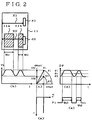
- Fig. 1 is a block diagram showing an embodiment of the invention constructed as a bar code reading device and Fig. 2 is a diagram for describing the operation of the device.
- An article 11 is a part of a finished product such as an automobile and is made, for example, of iron. Desired coded information as illustrated is provided at a predetermined position of the article 11 in the form of patterns 11a and 11b which produce reluctance change.
- the article 11 is shown in a side view or a sectional view in Fig. 1 and in a plan view in Fig. 2.
- the pattern 11a has a width Wal and the pattern 11b has a width Wb1.
- the coded information may have any desired contents.
- individual identifying information such as a manufacturing number may be assigned to the article 11 which is a part and this identifying information may be expressed by a pattern made according to a predetermined coding standard (e.g., a bar code pattern).
- the coded information however is not limited to individual identifying information of a part but it may be indentifying information of a finished product such as an autombile body number which is expressed in the form of a pattern made according to a predetermined coding standard (e.g., a bar code).
- Identifying information concerning a finished product need not be provided to all parts but it may be provided to one or more specific parts according to necessity. Likewise, identifying information of an individual part need not be provided to all parts but it may be provided to only one or more necessary parts.
- Coded information patterns may be provided at a predetermined position of the article 11 by a known method in the manufacturing process of the article 11 or after completion of manufacturing thereof.
- a necessary bar code pattern may be formed by changing permeability of the material of the article 11 at a position where the pattern is formed.
- permeability of the substance can be changed partially by subjecting it to a partial hardening by means of radiation of laser beam.
- a desired bar code pattern therefore is provided to the surface of the article 11 by a partial hardening by means of laser beam.
- a pattern whose permeability changes according to the bar code pattern can thereby be realized.
- the change in permeability according to the bar code pattern means a binary change according to which a black portion of the bar code represents a larger permeability value and a white portion of the bar code represents a smaller permeability value, or vice versa.
- a pattern may be provided by forming projections and depressions corresponding to a desired bar code pattern at a position where the pattern is to be provided in the article 11.
- a gap between the surface of the article 11 and a magnetic sensor changes in accordance with the configuration formed by the projections and depressions and this produces change in reluctance.
- the projections and depressions can be formed by any known method such as machining, etching or bonding of projections to a flat surface of the article 11.
- a conventional coded magnetic sheet may also be used for forming these projections and depressions.
- a pattern may be formed in such a manner that a mode of generation of eddy current of a conductive material (i.e., magnitude of eddy current loss) changes in accordance with a desired bar code pattern at a position where the pattern is to be formed in the article 11.
- the pattern exhibits a binary change in such a manner that the eddy current loss is larger in a black portion of the bar code and smaller in a white portion thereof, or vice versa.
- a pattern may be formed by covering the article 11 made of a relatively weak conductive material partially with a relatively good conductive material (e.g., copper) in black portions of a bar code.
- a pattern may be formed by covering the article 11 made of a relatively good conductive material partially with a relatively weak conductive material or non-conductive material in black portions of a bar code.
- Such partial covering can be realized by partial electroplating of the material to be covered or coating or printing of a liquid including necessary material.
- Reading of coded information provided on the article 11 is made by approaching a magnetic sensor 4 to the portion of the article 11 where the pattern is provided in a proper stage during assembling of a finished product or before or after such assembling.
- the magnetic sensor 4 is a mutual induction type magnetic sensor including a core 41 wound with a primary coil 4a and a secondary coil 4c and a core 42 wound with a primary coil 4b and a secondary coil 4d.
- the widths of the detecting end portions of the cores 41 and 42 are so determined that they are smaller than the minimum interval of white and black portions of the patterns 11a and 11b.
- the detecting end portions of the cores 41 and 42 are caused to approach the article 11. More specifically, the core 41 approaches and scans a portion where there is no pattern (e.g., a portion above or below the pattern) and the core 42 approaches and scans a portion where the pattern is provided.
- the scanning direction of the core 41 is designated by reference character X1 and the scanning direction of the core 42 by reference character X2.
- phase difference detection section 30 which detects phase difference D ⁇ between a composite mutual induction voltage induced in the secondary coils 4c and 4d and a reference ac signal sin ⁇ t.
- the phase difference detection section 30 comprises a reference signal generation section which generates reference ac signals sin t and cos t and a phase difference detection section which detects phase difference D ⁇ between mutual induction voltages in the secondary coils 4c and 4d and the reference ac signal sin ⁇ t.
- the reference signal generation section includes a clock oscillator 31, a synchronizing counter 32, ROMs 33 and 33b, D/A converters 34 and 34b and amplifiers 35 and 35b.
- the phase difference detection section includes an amplifer 36, a zero-cross circuit 37 and a latch circuit 38.
- the clock oscillator 31 generates a high rate and accurate clock signal in response to which the other circuits of the device are operated.
- the synchronizing counter 32 counts the clock signal generated by the clock oscillator 31 and supplies the count as an address signal to the ROM 33 and a latch circuit 38 of the phase difference detection section.
- the ROMs 33 and 33b store amplitude data corresponding to the reference ac signal and generate amplitude data of the reference ac signal in response to the address signal from the synchronizing counter 32.
- the ROM 33 stores amplitude data of sin ⁇ t and the ROM 33b stores amplitude data of cos ⁇ t.
- the ROMs 33 and 33b therefore provide two types of reference ac signals sin ⁇ t and cos ⁇ t by receiving the same address signal from the synchronizing counter 32. Two types of reference ac signals can be obtained also by accessing ROMs storing the same amplitude data by different address signals.
- the D/A converters 34 and 34b convert the digital amplitude data from the ROMs 33 and 33b to analog signals and supply them to the amplifiers 35 and 35b.
- the amplifiers 35 and 35b amplify the analog signals from the D/A converters 34 and 34b and supply the amplified signals as the reference ac signals sin ⁇ t and cos ⁇ t to the primary coils 4a and 4b.
- the frequency dividing number of the synchronizing counter 32 is M
- MM counts of the counter 32 correspond to the maximum phase angle 2 ⁇ radian (360 degrees) of the reference ac signals.
- one count of the synchronizing counter 32 represents a phase angle of 2 ⁇ /M radian.
- the amplifier 36 amplifies a composite value of the secondary voltages induced in the secondary coils 4c and 4d and supplies the amplified value to the zero-cross circuit 37.
- the zero-cross circuit 37 detects a zero-cross point from a negative voltage to a positive voltage in response to the mutual induction voltage (secondary voltage) induced in the secondary coils 4c and 4d of the magnetic sensor 4 and supplies a detection signal to the latch circuit 38.
- the latch circuit 38 latches a count of the synchronizing counter 32 which has started with a clock signal at the rise of the reference ac signals at a time point of generation of the detection signal from the zero-cross detection circuit 37 (zero-cross point).
- the value latched by the latch circuit 38 therefore constitutes phase difference D ⁇ between the reference ac signal and the mutual induction voltage (composite secondary output).
- the primary coil 4a of the core 41 is excited by the reference ac signal (sin ⁇ t) from the amplifier 35 and the primary coil 4b of the core 42 is excited by the reference ac signal (cos ⁇ t) from the amplifier 35b.
- the primay coils 4a and 4b are excited by ac signals of phase difference ⁇ /2 (90 degrees).
- the end portions of the cores 41 and 42 are caused to approach the article 11 and perform scanning in the horizontal direction. Since there is no pattern in the scanning route X1 of the core 41, a mutual induction voltage Va of a constant amplitude shown in Fig. 2(a) is induced in the secondary coil 4c of the core 41.
- the patterns 11a and 11b having different widths in the scanning route X2 of the core 42 and, accordingly, magnetic circuits having reluctances corresponding to the patterns 11a and 11b are formed between the core 42 and the article 11 and a mutual induction voltage Vb whose amplitude changes in accordance with reluctance change as shown in Fig.2(b) is induced in the secondary coil 4d of the core 42.
- the maximum value of the mutual induction voltage Vb is designated by Vb1 and the minimum value thereof by Vb2.
- a composite secondary voltage Vout of the mutual induction voltages Va and Vb appears in the secondary coils 4c and 4d and this composite secondary voltage Vout is supplied to the zero-cross circuit 37 through the amplifier 36.
- a vector representation of this state is shown in Fig. 2(c). Since the reference ac signal in the core 41 at this time is sin ⁇ t and the reference ac signal in the core 42 is cos ⁇ t, the composite secondary voltage Vout has a certain phase difference with respect to the reference ac signal of the core 41 (sin ⁇ t).
- the phase difference is ⁇ 1 in the figure and, assuming that the composite secondary voltage Vout generated when the mutual induction voltage Vb is at the minimum value Vb2 is designated by V2, the phase difference is ⁇ 2 in the figure.
- the latch circuit 38 thereby produces a phase difference signal D ⁇ which varies as the magnetic sensor 4 is moved horizontally.
- This phase difference signal D ⁇ is compared with a predetermined reference value ⁇ r by a comparison section 39 and the result of comparison is provided as a pulse signal P1 as shown in Fig. 2(e).
- This pulse signal P1 is a signal having pulse intervals Wa2 and Wb2 corresponding to variation in the phase difference signal D ⁇ . By detecting these pulse intervals, the intervals Wa1 and Wb1 of the patterns 11a and 11b can be recognized and the coded information can be read.
- phase difference between the composite value of mutual induction voltages of the primary coil and secondary coil excited by reference ac signals of different reference ac signals is detected in the above described embodiment, the phase difference can be accurately detected notwithstanding change in the distance between the magnetic sensor 4 and the article 11 and the bar code pattern can thereby be read.
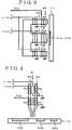
- Fig. 3 shows a modified example of the magnetic sensor 4.
- the same component parts as those in Fig. 1 are designated by the same reference characters and description thereof will be omitted.
- a magnetic sensor 40 is a mutual induction type magnetic sensor including a core 44 wound with a primary coil 4A and a secondary coil 4D, a core 45 wound with a primary coil 4B and a secondary coil 4E, and a core 46 wound with a primary coil 4C and a secondary coil 4F.
- the reference ac signal sin ⁇ t is supplied to the primary coils 4A and 4C of the cores 44 and 46 and the reference ac signal cos ⁇ t is supplied to the primary coil 4B of the core 45.
- the cross sectional area of each of the cores 44 and 46 i.e., area facing the article 11
- the secondary coils 4D and 4F of the cores 44 and 46 are equivalent to the secondary coil 4c of the core 41 of Fig. 1.
- this opposite pattern train is provided on both above and below the normal pattern train 11a, 11b, 11c, owing i.e., on the cores 44 and 46.
- the magentic sensor of Fig. 1 when the magnetic sensor 4 itself is inclined, the distances between the cores 41 and 42 and the article 11 become different from each other and accurate detection of the phase difference becomes difficult. According to the magnetic sensor 40 of Fig. 3, even when the sensor 40 is inclined, the cores 44 and 46 on both sides cancel the change in the distance due to the inclination of the magnetic sensor 40 and thereby make a compensation as if the distances between the cores 44, 46 and the article 11 were always the same, so that accurate detection of the phase difference is ensured.
- Figs. 4 and 5 show another embodiment of the coded information reading device according to the invention.
- Fig. 4 shows the entire construction of the magnetic sensor of the coded information reading device and
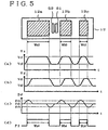
- Fig. 5 is a diagram for describing the operation of the reading device.
- An article 12 is of the same structure as the article 11 of Fig. 1 and is provided in predetermined positions thereof with patterns 12a, 12b and 12c which produce reluctance changes.
- the pattern 12a has a width Wa3
- the pattern 12b has a width Wb3
- the pattern 12c has a width Wc3.
- a magnetic sensor 5 is a mutual induction type magnetic sensor and includes a core 51 wound with a primary coil 5a and a secondary coil 5c and a core 52 wound with a primary coil 5b and a secondary coil 5d.
- the cores 41 and 42 are disposed vertically with respect ot the scanning direction whereas in the magnetic sensor 5, the cores 51 and 52 are disposed along the scanning direction.
- the interval between the cores 51 and 52 in the scanning direction is so determined that it is smaller than the minimum interval of black and white portions of the patterns 12a, 12b and 12c.
- the widths of the cores 51 and 52 should preferably be less than half the minimum interval of the black and white portions of the patterns 12a, 12b and 12c and be the same as each other.
- a phase difference detection section 30 and a comparison section 39 may be of the same construction as those of Fig. 1 so that description thereof will be omitted.
- the primary coil 5a of the core 51 is excited by the reference ac signal sin ⁇ t from the amplifier 35 and the primary coil 5b of the core 52 is excited by the reference ac signal cos ⁇ t of the amplifier 35b.
- the primary coils 5a and 5b are respectively excited by the reference ac signals having a phase difference ⁇ /2 (90 degrees).
- the end portions of the cores 51 and 52 are caused to approach the article 12 and perform scanning in the horizontal direction. Since the core 51 forms a magnetic circuit with the patterns 12a, 12b and 12c along the scanning route always prior to the core 52, the amplitude change in mutual induction voltage Vc induced in the secondary coil 5c of the core 51 is always in advance of mutual induction voltage Vd induced in the secondary coil 5d of the core 52.
- a time point at which the mutual induction voltage Vc changes from a minimum value Vc2 to a maximum value Vc1 and a time point at which the voltage Vc changes from the maximum value Vc1 to the minimum value Vc2 always appears prior to a time point at which the mutual induction voltage Vd changes from a minimum value Vd2 to a maximum value Vd1 and a time point at which the voltage Vd changes from the maximum value Vd1 to the minimum value Vd2.
- the cores 51 and 52 are connected in series, a composite secondary voltage of the mutual induction voltages Vc and Vd of the secondary coils 5c and 5d appears in the secondary coils 5c and 5d and this composite secondary voltage is supplied to a zero-cross circuit 37.
- the reference ac signal in the core 51 is sin ⁇ t and the reference ac signal in the core 52 is cos ⁇ t and, accordingly, the composite secondary voltage has a phase difference with respect to the reference ac signal sin ⁇ t.
- the change in the phase difference ⁇ is produced when the cores 51 and 52 cross the borders of the patterns 12a, 12b and 12c and the mutual induction voltages Vc and Vd of the secondary coils 5c and 5d respectively increase or decrease.
- the phase difference ⁇ is 45 degrees as will be understood from the vector diagram of Fig. 2(c).
- the phase difference ⁇ exceeds 45 degrees and then returns to 45 degrees again.
- the phase difference ⁇ becomes below 45 degrees and then returns to 45 degrees. Accordingly, the phase difference D oscillates up and down from 45 degrees as shown in Fig. 5(c).
- a latch circuit 38 produces a phase difference signal D ⁇ which changes as the magnetic sensor 5 is moved horizontally. Since this phase difference signal D ⁇ is a signal oscillating up and down as shown in Fig. 5, this phase difference signal D ⁇ is compared with predetermined reference values ⁇ ra and ⁇ rb by the comparison section 39 and the result of comparison is provided as a pulse signal P2.
- the comparison section 39 is composed of suitably combined comparator and flip-flops so that when D ⁇ ⁇ ⁇ ra, P2 will be set to 1 and, when D ⁇ ⁇ ⁇ rb, P2 will be reset to 0.
- This pulse signal P2 is a signal having pulse intervals Wa4, Wb4 and Wc4 corresponding to variation in the phase difference signal D ⁇ as shown in Fig. 5(d). By detecting these pulse intervals, the intervals Wa3, Wb3 and Wc3 of the patterns 12a, 12b and 12c can be recognized and the coded information can thereby be read.
- the phase difference between the reference ac signal and a composite value of mutual induction voltages of the secondary coils produced by the primary coils which are excited by reference ac signals of different phases is detected, so that the phase difference can be accurately detected and the bar code pattern can be read even if the distance between the magnetic sensor 5 and the article 12 changes.
- This scanning can be made by moving the hand holding the magnetic sensor, automatically moving the core within a casing of a magnetic sensor, or fixing the magnetic sensor which is positioned close to an article and moving the article.
- the binary bar code pattern signal which has thus been read is applied to an unillustrated recognition circuit where coded information corresponding to the pattern, i.e., individual identifying information assigned to a part of an article or identifying information of a finished product, is recognized.
- coded information corresponding to the pattern i.e., individual identifying information assigned to a part of an article or identifying information of a finished product.
- the recognized information can be suitably utilized such, for example, as product management including manufacturing management or maintenance management of each individual part or a finished product.
- identifying information such as a part identifying number or a manufacturing number affixed to a part of a finished product or a manufacturing number of a whole automobile body can be automatically read in a production site such as an automobile production line where an article made of metal, e.g., cast iron, is used as a part.
- Automation of product management or incorporating of product management in FMS (flexible manufacturing system) can therefore be facilitated by supplying the automatically read identifying information to a control device such as a computer.
- the identifying Information is one for a finished product
- the information can be utilized for identifying an individual article when it has been stolen.
- an automobile body with an automobile body number according to the invention it is almost impossible to alter the pattern. Accordingly, when the automobile has been stolen, the stolen automobile will be identified by the automobile body number provided according to the invention even if a visibly displayed portion of the automobile body number is fraudulently altered.
- the coding standard for the pattern is not limited to a bar code but other types of patterns may also be used.
- the pattern need necessarily be attached directly to the article but a metal piece, metal foil or paper on which the pattern is provided may be bonded to the article.
- plural magnetic sensors may be used and phase difference signals provided by these magnetic sensors may be sequentially scanned.
- phase difference between the reference ac signal and the mutual induction voltage is relatively small, such small phase difference can be detected easily by adopting a resonance circuit or adopting a bridge circuit in a resonance circuit.
Description
- This invention relates to a system for reading coded information which is expressed by a pattern such as a bar code pattern and, more particularly, to an improvement of a reading system of a type in which a pattern is formed with magnetically different materials and this pattern is read by an electromagnetic sensor.
- Known in the art is a coded pattern reading method according to which a black and white bar code pattern in which light reflection property varies depending upon the black and white portions is read in an optical manner. The optical type coded pattern reading method has the disadvantage that, when reflection and permeation of light are hindered due to depostion of dust on the black and white pattern section or the reading unit, it becomes extremely difficult to detect the pattern.
- The prior art optical type bar code system can be applied only to a case where an article on which a pattern should be provided is made of a material such as paper on which the pattern can be printed or an article on which a printed pattern paper can be bonded semi-fixedly so that it will not come off easily. It is difficult to apply this optical type bar code system to other articles. If, for example, one attempts to apply the optical type bar code system to a case where a manufacturing number should be affixed in the form of a pattern to an article made of metal such as cast iron, he will not be able to print an optical type bar code pattern on the cast iron itself. Bonding of a pattern printed paper on the cast iron article will not work because it will easily come off from such cast iron article and/or become soiled.
- U.S. Patent No. 4,883,949 proposes a magnetic type coded data reading device according to which a patterned code representation magnetic sheet is bonded to an article and coded information on the code representation magnetic sheet is read by means of a magnetic sensor employing a mutual induction coil comprising a primary coil which is excited by ac and a secondary coil which thereby generates a mutual induction voltage. According to the code representation magnetic sheet to be read by this coded data reading device, coded information can be read magnetically even when it cannot be read optically because the pattern surface is soiled with dust. In this coded data reading device, the code representation magnetic sheet which is prepared separately must be attached to the article semi-fixedly to prevent ready coming off of the sheet from the article as in the case of the optical type reading device; however, there still remains the likelihood of coming off of the magnetic sheet.
- This prior art coded data reading device identifies coded information by operating an amplitude value of mutual induction voltage produced in the secondary coil of the magnetic sensor by a microcomputer or the like computing device, utilizing the phenomenon that the amplitude level of mutual induction voltage produced in the secondary coil of the mutual induction coil varies with the width, thickness and interval of a metal portion of the code representation magnetic sheet. Since, however, the amplitude value of mutual induction voltage produced in the secondary coil varies also with the distance (gap) between the code representation magnetic sheet and the mutual induction coil, a protection film is normally provided on the surface of the magnetic sheet which constitutes a guide surface for the mutual induction coil to provide a flat surface with a view to maintaining the distance constant during reading of the coded information. Accordingly, there arises the problem that, when the surface of the magnetic sheet has become uneven due to unintended deposition of paint or the like on the surface of the magnetic sheet after the magnetic sheet has been bonded to the metal material such as case iron, the distance between the magnetic sheet and the mutual induction coil is changed, with the result that accurate reading of the coded information becomes difficult. Further, since the amplitude level of the mutual induction voltage changes under the influence of an environmental change such as change in the ambient temperature, this factor also adversely affects the accuracy in reading of the coded information.
- It is, therefore, an object of the invention to provide a coded information reading system capable of reading coded information accurately without being adversely affected by change in the amplitude level of an induced output signal due to the state of use or environmental change.
- The object of the invention is achieved by the features of
claim 1. - The coded information reading system according to the invention comprises pattern recording means having a pattern formed by first and second materials of mutually different magnetic characters in an arrangement corresponding to desired coded information; sensor means including coil means excited by a reference ac signal for producing an induced output signal, said induced output signal exhibiting electrical phases corresponding to existence of the first and second materials in the pattern when said coil means has approached the pattern; and signal forming means for measuring the electrical phases of the induced output signal from said coil means and forming, in correspondence to measured data of the electrical phases, a pattern reading signal corresponding to the first and second materials.
- Since the first and second materials which constitute the pattern are magnetically different from each other, the induced output signal from the coil means exhibits change corresponding to existence of the first and second materials in the pattern when the coil means has approached the pattern. This change includes change in the electrical phase. For example, for producing a marked change in the electrical phase, the coil means preferably include plural primary coils which are excited by plural reference ac signals which are different in phase from each other. For another example, although the change is not so remarkable as in the case where the primary coils are excited by plural reference ac signals, change in the electrical phase can be recognized also in a case where the primary coil is excited by a single reference ac signal.
- Thus, having regard to the phenomenon that the induced output signal exhibits an electrical phase corresponding to existence of the first and second materials in the pattern, the signal forming means is provided and the electrical phase of the induced output signal is measured by this signal forming means. On the basis of measured data of the electrical phase, a pattern reading signal corresponding to the first and second materials is formed. The pattern reading signal thus obtained is a signal corresponding to existence of the first and second materials constituting the pattern, e.g., a square pulse signal corresponding to existence of the first and second materials. Once this pattern reading signal has been obtained, coded information contained in the pattern can be recognized by a proper decoding processing. By way of example, a known bar code pattern may be utilized as the coded pattern. In this case, decoding of the pattern reading signal is made by using a known decoding processing for a bar code pattern.
- The electrical phase of the induced output signal changes only in accordance with existence of the first and second materials in the pattern and is not affected by variation in the distance between the sensor means and the pattern unless the sensor means is inclined to the pattern surface, nor is the electrical phase affected by the environmental change such as change in the ambient temperature. Accordingly, coded information can be read accurately regardless of the state of use and the environmental change such as in a case where the pattern surface has become uneven due to unintended depositon of paint or the like.
- By way of example, the coil means may include two primary coils which are excited by two reference ac signals which are different in phase from each other. In this case, the respective primary coils may be spaced from each other so that, when one of the primary coils approaches the pattern, the other primary coil cannot approach the pattern. By this arrangement, the amplitude level of a first induced signal which is induced by the primary coil which approaches the pattern exhibits change corresponding to the pattern and the amplitude level of a second induced signal which is induced by the other primary coil does not exhibit change corresponding to the pattern. Since the exciting signals are different in phase, the first induced signal and the second induced signal are different in phase form each other. Accordingly, an induced output signal which is a composite signal of the first and second induced signals changes in its electrical phase in accordance with the change in the amplitude level of the first induced signal and, consequently, it exhibits an electrical phase corresponding to the first and second materials in the pattern (i.e., phase difference relative to the reference ac signal).
- By way of example, the pattern recording means may include not only a first pattern formed by first and second materials which are magnetically different from each other in an arrangement corresponding to desired coded information but also a second pattern formed by two magnetically different materials and arranged with opposite characteristics to the first pattern. In this case, the coil means may include two primary coils whch are excited by two reference ac signals which are different in phase from each other. These primary coils may be suitably spaced from each other so that, when one of the primary coils approaches the first pattern, the other primary coil approaches the second pattern. By this arrangement, the amplitude level of a first induced signal induced by the primary coil which approaches the first pattern exhibits a change corresponding to the pattern and the amplitude level of a second induced signal induced by the primary coil which approaches the second pattern exhibits a change which is of opposite characteristics corresponding to the second pattern. Since the phase of respective exciting signals is different, the first and second induced signals are different in the electrical phase. Accordingly, an induced output signal which is a composite signal of the first and second induced signals changes in its electrical phase to a larger degree in accordance with a differential change in the amplitude levels of the first and second induced signals and, consequently, it exhibits a larger electrical phase (phase difference relative to the reference ac signal) corresponding to existence of the first and second materials in the pattern. The accuracy in measurement of electrical phase therefore is improved with resulting improvement in accuracy in reading of the pattern.
- The two materials which constitute the second pattern (the third and fourth materials) may have opposite magnetic characteristics to the first and second materials which constitute the first pattern. For example, if permeability of the first material is larger than that of the second material, permeability of the third material in the second pattern which corresponds to the first material should be smaller than that of the fourth material which corresponds to the second material. As the third and fourth materials, the same materials as the first and second materials may be employed. In this case, the second pattern can be formed by arranging the first and second materials in opposite relation to the first pattern.
- Any material may be used as the first and second materials which constitute the pattern so long as they are magnetically different from each other. For example, as described above, permeability of one of the first and second materials may be larger than that of the other material. In that case, difference in reluctance is produced in accordance with difference in permeability. Alternatively, conductivity of one of the first and second materials may be larger than that of the other material. In that case, difference in the manner of generation of an eddy current is produced in accordance with difference in conductivity and difference in reluctance is thereby produced. A pattern may be formed by combining permeability and conductivity. Difference in the magnetic property may be produced by differring the manner of magnetization.
- One or both of the first and second materials may be the same as the material of a base portion of the pattern recording means. For example, in a case where the base portion of the pattern recording means is made of a magnetic substance such as iron, permeability of the material can be changed by subjecting the base portion to a partial hardening by means of laser beam, so that this hardening method may be adopted. Alternatively, in a case where the base portion of the pattern recording means is made of a magnetic substance such as iron, a pattern may be formed by forming a projection and a depression on the surface of the magnetic substance. In this case, the first material is formed by the projection of the magnetic substance and the second material by the depression thereof (i.e., air or a non-magnetic substance filled in the depression). A magnetic or conductive substance may be attached partially in the form of a desired pattern to the base portion of the pattern recording means consisting of a magnetic, conductive, non-magnetic or non-conductive substance. Such attaching of the magnetic or conductive substance may be made by a suitable method such as partial electroplating, coating of liquid including a necessary material, printing or baking. As the pattern recording means, a metal foil or a sheet of paper to which a necessary magnetic, conductive, non-magnetic or non-conductive material is partially attached may be used.
- Since permeability can be changed by partial hardening by means of laser beam, a pattern corresponding to desired coded information can be easily formed, for example, with two different portions having a large permeability and a small permeability. Since this pattern is fixedly recorded in the base portion of the pattern recording means, no problem of coming off which arises in the case of bonding a magnetic sheet will never arise. Besides, a desired coded pattern can be formed relatively easily without necessity for a troublesome processing such as machining.
- The coded information recording medium may comprise a pattern recoding surface which has, in parallel to each other, the first pattern formed by first and second materials of mutually different magnetic characters in an arrangement corresponding to desired coded information and a second pattern formed by two materials of mutually different magnetic characters and arranged with opposite characteristics to the first pattern.
- The coded information recording medium having not only the first pattern corresponding to desired coded information but also the second pattern with opposite characteristics to the first pattern contributes to improving the reading accuracy when it is used in the above described phase type coded information reading system.
- The coded information reading system may comprise: coil means which has three cores in the form of projection each having a coil to produce the induced output signal, said three cores being arranged between second and third said cores and that when said first core approaches said pattern, the other cores do not approach said pattern, and said induced output signal representing the difference of materials in said pattern when said coil means has approached said pattern; and signal forming means responsive to the induced output signal from said coil means for forming a pattern reading signal corresponding to the difference of materials.
- Since the coil means has three cores each having a coil such that when the first core approaches the pattern, the other coils do not approach the pattern, there is produced a superior advantage taht accurate pattern reading can be achieved even when the sensor means approaches in an inclined relationship to the surface of the pattern recording means.
- According to the coded information reading system of the present invention, a product management system employing a coded pattern such as a bar code pattern can be introduced in the field including cast iron and metal products in which the conventional optical bar code system cannot be introduced. More specifically, identifying information is assigned to each individual part of a finished product, this identifying information is represented by a pattern following a predetermined coding standard, and a pattern which generates reluctance change corresponding to this pattern is provided to each individual part in the manner described above. By causing the magnetic sensor to approach the portion of the part provided with the pattern during or before and after assembling of the finished product, a magnetic circuit is formed between the portion provided with the pattern and the magnetic sensor and, by detecting reluctance change corresponding to the pattern by the magnetic sensor, the pattern is read. The identifying information assigned to the part is recognized on the basis of the read pattern and is utilized for the product management such as a production management or a maintenance management.
- According to the invention, in a productin site such as an automobile production line where an article made of metal such as cast iron is used as a part of a finished product, indetifying information such as a part identifying number, a part manufacturing number or a manufacturing number of a whole automobile body can be automatically read whereby the product management can be readily automatized or incorporated into FMS (flexible manufacturing system). In a case where identifying information concerning a finished product is assigned to a finished product in accordance with the invention, the finished product can be recognized when it has been stolen. When, for example, an automobile body number is assigned to an automobile according to the invention, it is almost impossible to alter the pattern. When, accordingly, the automobile has been stolen, the automobile can be recognized by the automobile number provided according to the invention even if the visible display portion of the body number has been fraudulently altered.
- Embodiments of the invention will now be described with reference to the accompanying drawings.
- In the accompanying drawings,
- Fig. 1 is a block diagram showing an embodiment of the coded information reading system according to the invention;
- Fig. 2 is a plan view of the pattern recorded surface and a view for describing the operation of the reading system;
- Fig. 3 is a schematic side view of a modified example of a magnetic sensor used in the above embodiment;
- Fig. 4 is a schematic side view showing another embodiment of the coded information reading system according to the invention particularly in the portion including the magnetic sensor;
- Fig. 5 is a plan view of the pattern recorded surface and a view for describing the operation of the reading system in the same embodiment;
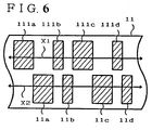
- Fig. 6 is a plan view showing a modified example of a coded information pattern.
- Fig. 1 is a block diagram showing an embodiment of the invention constructed as a bar code reading device and Fig. 2 is a diagram for describing the operation of the device.
- An
article 11 is a part of a finished product such as an automobile and is made, for example, of iron. Desired coded information as illustrated is provided at a predetermined position of thearticle 11 in the form ofpatterns article 11 is shown in a side view or a sectional view in Fig. 1 and in a plan view in Fig. 2. Thepattern 11a has a width Wal and thepattern 11b has a width Wb1. - As an example of the coded information, a known bar code pattern is utilized. The coded information may have any desired contents. For example, individual identifying information such as a manufacturing number may be assigned to the
article 11 which is a part and this identifying information may be expressed by a pattern made according to a predetermined coding standard (e.g., a bar code pattern). The coded information however is not limited to individual identifying information of a part but it may be indentifying information of a finished product such as an autombile body number which is expressed in the form of a pattern made according to a predetermined coding standard (e.g., a bar code). - Identifying information concerning a finished product need not be provided to all parts but it may be provided to one or more specific parts according to necessity. Likewise, identifying information of an individual part need not be provided to all parts but it may be provided to only one or more necessary parts.
- Coded information patterns may be provided at a predetermined position of the
article 11 by a known method in the manufacturing process of thearticle 11 or after completion of manufacturing thereof. For example, a necessary bar code pattern may be formed by changing permeability of the material of thearticle 11 at a position where the pattern is formed. - As to a magnetic substance such as iron, permeability of the substance can be changed partially by subjecting it to a partial hardening by means of radiation of laser beam. A desired bar code pattern therefore is provided to the surface of the
article 11 by a partial hardening by means of laser beam. A pattern whose permeability changes according to the bar code pattern can thereby be realized. The change in permeability according to the bar code pattern means a binary change according to which a black portion of the bar code represents a larger permeability value and a white portion of the bar code represents a smaller permeability value, or vice versa. - Alternatively, a pattern may be provided by forming projections and depressions corresponding to a desired bar code pattern at a position where the pattern is to be provided in the
article 11. A gap between the surface of thearticle 11 and a magnetic sensor changes in accordance with the configuration formed by the projections and depressions and this produces change in reluctance. The projections and depressions can be formed by any known method such as machining, etching or bonding of projections to a flat surface of thearticle 11. A conventional coded magnetic sheet may also be used for forming these projections and depressions. - Alternatively further, a pattern may be formed in such a manner that a mode of generation of eddy current of a conductive material (i.e., magnitude of eddy current loss) changes in accordance with a desired bar code pattern at a position where the pattern is to be formed in the
article 11. In this case, the pattern exhibits a binary change in such a manner that the eddy current loss is larger in a black portion of the bar code and smaller in a white portion thereof, or vice versa. For example, a pattern may be formed by covering thearticle 11 made of a relatively weak conductive material partially with a relatively good conductive material (e.g., copper) in black portions of a bar code. Conversely, a pattern may be formed by covering thearticle 11 made of a relatively good conductive material partially with a relatively weak conductive material or non-conductive material in black portions of a bar code. Such partial covering can be realized by partial electroplating of the material to be covered or coating or printing of a liquid including necessary material. - Reading of coded information provided on the
article 11 is made by approaching amagnetic sensor 4 to the portion of thearticle 11 where the pattern is provided in a proper stage during assembling of a finished product or before or after such assembling. Themagnetic sensor 4 is a mutual induction type magnetic sensor including a core 41 wound with a primary coil 4a and asecondary coil 4c and a core 42 wound with aprimary coil 4b and asecondary coil 4d. - The widths of the detecting end portions of the
cores patterns patterns cores article 11. More specifically, the core 41 approaches and scans a portion where there is no pattern (e.g., a portion above or below the pattern) and the core 42 approaches and scans a portion where the pattern is provided. In Fig. 2, the scanning direction of thecore 41 is designated by reference character X1 and the scanning direction of the core 42 by reference character X2. By forming, for example, an integral sensor by connecting the other end portions of thecores - Description will now be made about construction of a phase
difference detection section 30 which detects phase difference Dθ between a composite mutual induction voltage induced in thesecondary coils - In Fig. 1, the phase
difference detection section 30 comprises a reference signal generation section which generates reference ac signals sin t and cos t and a phase difference detection section which detects phase difference Dθ between mutual induction voltages in thesecondary coils - The reference signal generation section includes a
clock oscillator 31, a synchronizingcounter 32,ROMs A converters amplifiers amplifer 36, a zero-cross circuit 37 and alatch circuit 38. - The
clock oscillator 31 generates a high rate and accurate clock signal in response to which the other circuits of the device are operated. - The synchronizing counter 32 counts the clock signal generated by the
clock oscillator 31 and supplies the count as an address signal to theROM 33 and alatch circuit 38 of the phase difference detection section. - The
ROMs counter 32. TheROM 33 stores amplitude data of sin ωt and theROM 33b stores amplitude data of cos ωt. TheROMs counter 32. Two types of reference ac signals can be obtained also by accessing ROMs storing the same amplitude data by different address signals. - The D/
A converters ROMs amplifiers amplifiers A converters primary coils 4a and 4b. Assuming that the frequency dividing number of the synchronizingcounter 32 is M, MM counts of thecounter 32 correspond to the maximum phase angle 2π radian (360 degrees) of the reference ac signals. In other words, one count of the synchronizingcounter 32 represents a phase angle of 2π /M radian. - The
amplifier 36 amplifies a composite value of the secondary voltages induced in thesecondary coils cross circuit 37. The zero-cross circuit 37 detects a zero-cross point from a negative voltage to a positive voltage in response to the mutual induction voltage (secondary voltage) induced in thesecondary coils magnetic sensor 4 and supplies a detection signal to thelatch circuit 38. Thelatch circuit 38 latches a count of the synchronizingcounter 32 which has started with a clock signal at the rise of the reference ac signals at a time point of generation of the detection signal from the zero-cross detection circuit 37 (zero-cross point). The value latched by thelatch circuit 38 therefore constitutes phase difference Dθ between the reference ac signal and the mutual induction voltage (composite secondary output). - Referring to Fig. 2, the operation of this embodiment will be described.
- The primary coil 4a of the
core 41 is excited by the reference ac signal (sin ω t) from theamplifier 35 and theprimary coil 4b of thecore 42 is excited by the reference ac signal (cos ω t) from theamplifier 35b. In other words, the primay coils 4a and 4b are excited by ac signals of phase difference π/2 (90 degrees). The end portions of thecores article 11 and perform scanning in the horizontal direction. Since there is no pattern in the scanning route X1 of the core 41, a mutual induction voltage Va of a constant amplitude shown in Fig. 2(a) is induced in thesecondary coil 4c of thecore 41. - On the other hand, there are the
patterns core 42 and, accordingly, magnetic circuits having reluctances corresponding to thepatterns article 11 and a mutual induction voltage Vb whose amplitude changes in accordance with reluctance change as shown in Fig.2(b) is induced in thesecondary coil 4d of thecore 42. The maximum value of the mutual induction voltage Vb is designated by Vb1 and the minimum value thereof by Vb2. - Since the
secondary coils cores secondary coils cross circuit 37 through theamplifier 36. A vector representation of this state is shown in Fig. 2(c). Since the reference ac signal in the core 41 at this time is sin ω t and the reference ac signal in thecore 42 is cos ω t, the composite secondary voltage Vout has a certain phase difference with respect to the reference ac signal of the core 41 (sin ω t). Assuming that the composite secondary voltage Vout generated when the mutual induction voltage Vb of thesecondary coil 4d is at the maximum vlaue Vbl is designated by VI, the phase difference isθ 1 in the figure and, assuming that the composite secondary voltage Vout generated when the mutual induction voltage Vb is at the minimum value Vb2 is designated by V2, the phase difference isθ 2 in the figure. - The
phase difference θ 1 is phase difference between the composite secondary voltage Vout = V1 generated when thecore 42 is located in the middle of thepatterns secondary coil 4d, and the reference ac signal (sin ωt). Thephase difference θ 2 is phase difference between the composite secondary voltage Vout = V2 generated when thecore 42 is located in the portion where there are nopattern secondary coil 4c of thecore 41 and thesecondary coil 4d of the core 42, and the reference ac signal (sin ω t). Since the mutual induction voltage Va induced in thesecondary coil 4c of thecore 41 is of the same magnitude as the mutual induction voltage Vb induced in thesecondary coil 4d of the core 42, thephase difference θ 2 is 45 degrees. - The
latch circuit 38 thereby produces a phase difference signal Dθ which varies as themagnetic sensor 4 is moved horizontally. This phase difference signal Dθ is compared with a predetermined reference value θ r by acomparison section 39 and the result of comparison is provided as a pulse signal P1 as shown in Fig. 2(e). When, for example, Dθ ≧ θr, P1 = 1 is produced and when Dθ < θ r, P1 = 0 is produced. This pulse signal P1 is a signal having pulse intervals Wa2 and Wb2 corresponding to variation in the phase difference signal Dθ . By detecting these pulse intervals, the intervals Wa1 and Wb1 of thepatterns - Since, as described above, phase difference between the composite value of mutual induction voltages of the primary coil and secondary coil excited by reference ac signals of different reference ac signals is detected in the above described embodiment, the phase difference can be accurately detected notwithstanding change in the distance between the
magnetic sensor 4 and thearticle 11 and the bar code pattern can thereby be read. - In the embodiment shown in Fig. 1, there is no pattern in the scanning route X1 of the
core 41. Alternatively, as shown in Fig. 6,patterns patterns cores - Fig. 3 shows a modified example of the
magnetic sensor 4. In Fig. 3, the same component parts as those in Fig. 1 are designated by the same reference characters and description thereof will be omitted. - A
magnetic sensor 40 is a mutual induction type magnetic sensor including a core 44 wound with aprimary coil 4A and asecondary coil 4D, a core 45 wound with aprimary coil 4B and asecondary coil 4E, and a core 46 wound with aprimary coil 4C and asecondary coil 4F. - The reference ac signal sin ω t is supplied to the
primary coils cores primary coil 4B of thecore 45. The cross sectional area of each of thecores 44 and 46 (i.e., area facing the article 11) is half that of thecore 45. Therefore, thesecondary coils cores secondary coil 4c of thecore 41 of Fig. 1. In a case where theopposite pattern train normal pattern train cores - In the case of the magentic sensor of Fig. 1, when the
magnetic sensor 4 itself is inclined, the distances between thecores article 11 become different from each other and accurate detection of the phase difference becomes difficult. According to themagnetic sensor 40 of Fig. 3, even when thesensor 40 is inclined, thecores magnetic sensor 40 and thereby make a compensation as if the distances between thecores article 11 were always the same, so that accurate detection of the phase difference is ensured. - Figs. 4 and 5 show another embodiment of the coded information reading device according to the invention. Fig. 4 shows the entire construction of the magnetic sensor of the coded information reading device and Fig. 5 is a diagram for describing the operation of the reading device.
- An
article 12 is of the same structure as thearticle 11 of Fig. 1 and is provided in predetermined positions thereof withpatterns pattern 12a has a width Wa3, thepattern 12b has a width Wb3 and thepattern 12c has a width Wc3. - A
magnetic sensor 5 is a mutual induction type magnetic sensor and includes a core 51 wound with aprimary coil 5a and asecondary coil 5c and a core 52 wound with aprimary coil 5b and asecondary coil 5d. In themagnetic sensor 4 of Fig. 2, thecores magnetic sensor 5, thecores - The interval between the
cores patterns cores patterns - In the embodiment of Fig. 4, a phase
difference detection section 30 and acomparison section 39 may be of the same construction as those of Fig. 1 so that description thereof will be omitted. - Referring to Fig. 5, the operation of this embodiment will be described.
- The
primary coil 5a of thecore 51 is excited by the reference ac signal sin ω t from theamplifier 35 and theprimary coil 5b of thecore 52 is excited by the reference ac signal cos ω t of theamplifier 35b. In other words, theprimary coils - The end portions of the
cores article 12 and perform scanning in the horizontal direction. Since the core 51 forms a magnetic circuit with thepatterns core 52, the amplitude change in mutual induction voltage Vc induced in thesecondary coil 5c of thecore 51 is always in advance of mutual induction voltage Vd induced in thesecondary coil 5d of thecore 52. In other words, a time point at which the mutual induction voltage Vc changes from a minimum value Vc2 to a maximum value Vc1 and a time point at which the voltage Vc changes from the maximum value Vc1 to the minimum value Vc2 always appears prior to a time point at which the mutual induction voltage Vd changes from a minimum value Vd2 to a maximum value Vd1 and a time point at which the voltage Vd changes from the maximum value Vd1 to the minimum value Vd2. - Since the
cores secondary coils secondary coils cross circuit 37. At this time, the reference ac signal in thecore 51 is sin ω t and the reference ac signal in thecore 52 is cos ω t and, accordingly, the composite secondary voltage has a phase difference with respect to the reference ac signal sin ω t. - The change in the phase difference θ is produced when the
cores patterns secondary coils - A
latch circuit 38 produces a phase difference signal Dθ which changes as themagnetic sensor 5 is moved horizontally. Since this phase difference signal Dθ is a signal oscillating up and down as shown in Fig. 5, this phase difference signal Dθ is compared with predetermined reference values θ ra and θ rb by thecomparison section 39 and the result of comparison is provided as a pulse signal P2. In this case, thecomparison section 39 is composed of suitably combined comparator and flip-flops so that when Dθ ≧ θra, P2 will be set to 1 and, when Dθ ≧ θrb, P2 will be reset to 0. This pulse signal P2 is a signal having pulse intervals Wa4, Wb4 and Wc4 corresponding to variation in the phase difference signal Dθ as shown in Fig. 5(d). By detecting these pulse intervals, the intervals Wa3, Wb3 and Wc3 of thepatterns - According to the above described embodiment, the phase difference between the reference ac signal and a composite value of mutual induction voltages of the secondary coils produced by the primary coils which are excited by reference ac signals of different phases is detected, so that the phase difference can be accurately detected and the bar code pattern can be read even if the distance between the
magnetic sensor 5 and thearticle 12 changes. - In the above described embodiment, it is necessary to cause the bar code pattern to be scanned horizontally for enabling reading of a continuous bar code. This scanning can be made by moving the hand holding the magnetic sensor, automatically moving the core within a casing of a magnetic sensor, or fixing the magnetic sensor which is positioned close to an article and moving the article.
- The binary bar code pattern signal which has thus been read is applied to an unillustrated recognition circuit where coded information corresponding to the pattern, i.e., individual identifying information assigned to a part of an article or identifying information of a finished product, is recognized. The recognized information can be suitably utilized such, for example, as product management including manufacturing management or maintenance management of each individual part or a finished product.
- As described above, according to the invention, identifying information such as a part identifying number or a manufacturing number affixed to a part of a finished product or a manufacturing number of a whole automobile body can be automatically read in a production site such as an automobile production line where an article made of metal, e.g., cast iron, is used as a part. Automation of product management or incorporating of product management in FMS (flexible manufacturing system) can therefore be facilitated by supplying the automatically read identifying information to a control device such as a computer.
- In a case where the identifying Information is one for a finished product, the information can be utilized for identifying an individual article when it has been stolen. By providing, for example, an automobile body with an automobile body number according to the invention, it is almost impossible to alter the pattern. Accordingly, when the automobile has been stolen, the stolen automobile will be identified by the automobile body number provided according to the invention even if a visibly displayed portion of the automobile body number is fraudulently altered.
- The coding standard for the pattern is not limited to a bar code but other types of patterns may also be used. The pattern need necessarily be attached directly to the article but a metal piece, metal foil or paper on which the pattern is provided may be bonded to the article. In the above described embodiment, description has been made about the case where the magnetic sensor is used for scanning. Alternatively, plural magnetic sensors may be used and phase difference signals provided by these magnetic sensors may be sequentially scanned. In the above described embodiment, when the phase difference between the reference ac signal and the mutual induction voltage is relatively small, such small phase difference can be detected easily by adopting a resonance circuit or adopting a bridge circuit in a resonance circuit.
Claims (14)
- A coded pattern information reading system comprising:pattern recording means (11;12) having a pattern recorded therein,said pattern being formed of a first material (11a,11b;12a-12c;111a-111d) and a second material (11;12) which are provided in an arrangement corresponding to desired coded information,said first material (11a,11b;12a-12c;111a-111d) and said second material (11;12) are mutually different in magnetic response characteristics;sensor means (4;40;5) including coil means for detecting said first material (11a,11b;12a-12c;111a-111d) and said second material (11;12), andsignal forming means (30,39) responsive to an output of said sensor means (4;40;5), for forming a pattern signal determining information represented by said pattern,characterized in thatsaid sensor means (4;40;5) include plural sensing sections (41,42;44-46;51,52) each having coil means (4a-4d;4A-4F;5a-5d),said coil means (4a-4d;4A-4F;5a-5d) of at least two of the sensing sections (41,42;44-46;51,52) are excited by respective ac signals different in phase from each other,said sensor means (4;40;5) being displaceable relative to said pattern across said first and second materials (11,12,11a,11b;12a-12c;111a-111d) when scanning said pattern so that a signal responsive to presence of said first and second materials (11,12,11a,11b;12a-12c; 111a-111d) is induced in at least one of said sensing sections (41,42;41,46;51,52),said sensor means (4;40;5) produce a composite induced output signal (VOUT) having an electrical phase reflecting said presence of said first and second material (11,12,11a,11b;12a-12c;111a-111d); andsaid signal forming means (30,39) measures the electrical phase of the composite induced output signal (vOUT) produced from said sensor means (4;40; 5) and forms, on the basis of a measurement of the electrical phase, the pattern signal determining information represented by said pattern.
- A coded pattern information reading system as defined in claim 1 wherein said sensing sections (41,42;44-46) are spaced from each other in a direction substantially perpendicular to a direction in which said sensor means (4;40;5) scans the pattern, in such a manner that, when scanning the pattern, one of the sensing sections (42;45) faces the pattern while the other sensing section (42;44,46) face a portion of the pattern recording means (11,12) where there is not pattern.
- A coded pattern information reading system as defined in claim 1, whereinsaid pattern is a first pattern,said pattern recording means (11) also has a second pattern recorded therein in parallel to said first pattern, said second pattern being formed of third and fourth materials (111a-111d,11) which are capable of exhibiting different magnetic response characteristics and which are provided in an arrangement inversely to the arrangement of said first and second materials (11a-11d,11) of said first pattern, in such a manner that, when said sensor means (4,5) scans the pattern, one of the sensing sections (41) faces the first pattern while the other sensing section (42) faces the second pattern.
- A coded pattern information reading system as defined in claim 1 wherein said sensing means (40) comprises first and second sensing sections (45,44) which are excited by first and second reference ac signals different in phase from each other, and whereinsaid sensor means (40) further comprises a third sensing section (46) which is excited by the second reference ac signal,said second and third sensing sections (44,46) are disposed at both sides of the first sensing section (45), and said first, second and third sensing sections (44-46) are spaced from each other in such a manner that, when said sensor means (40) scans the pattern, the first sensing section (45) faces the pattern (11a,11b) while the other sensing sections (44,46) face a portion of the pattern recording means (11) where there is no pattern.
- A coded pattern information reading system as defined in claim 1, whereinsaid pattern is a first pattern,said pattern recording means (11) also has second and third patterns recorded therein at both sides of said first pattern in parallel to said first pattern, said second pattern being formed of third and fourth materials (111a-111d) which are capable of exhibiting different magnetic response characteristics and which are provided in an arrangement inversely to the arrangement of said first and second pattern materials of said first pattern, said third pattern being formed in the same manner as said second pattern,said sensor means comprises first and second sensing sections (45,44) which are excited by first and second reference ac signals different in phase from each other, andsaid sensor means further comprises a third sensing section (46) which is excited by the second reference ac signal,said second and third sensing sections (44,46) are disposed at both sides of the first sensing section (45), andsaid first, second and third sensing sections (44-46) are spaced from each other in such a manner that, when said sensor means scans the pattern, the first sensing section (45) faces the first pattern while the second and third sensing sections (44,46) face the second and third patterns respectively.
- A coded pattern information reading system as defined in claim 1 wherein said sensing sections (51,52) are spaced from each other in a same direction as a direction in which said sensor means (5) scans the pattern.
- A coded pattern information reading system as defined in one of claims 1-6 wherein said pattern is made in the form of a bar code pattern.
- A coded pattern information reading system as defined in one of claims 1-6 wherein permeability of one of the first and second materials (11a,11b;11) is larger than permeability of the other.
- A coded pattern information reading system as defined in one of claims 1-6 wherein conductivity of one of the first and second materials (11a,11b;11) is larger than conductivity of the other.
- A coded pattern information reading system as defined in one of claims 1-6 wherein said first and second materials (11a,11b;11) are magnetized and are different in their magnetizing characteristic from each other.
- A coded pattern information reading system as defined in one of claims 1-10 wherein said pattern recording means has a base portion of a predetermined material, one (11) of the first and second materials (11a,11b; 11) of the pattern is of a same material as the base portion, and the other (11a,11b) of the first and second pattern elements is of another material (11a, 11b) and is attached to the base portion.
- A coded pattern information reading system as defined in one of claims 1-6 wherein said pattern recording means has a base portion made of a magnetic substance having a permeability which is partially changed in accordance with the pattern by a laser beam hardening process, so that said first and second pattern elements are formed.
- A coded pattern information reading system as defined in one of claims 1-12 wherein said signal forming means includes first means (30) for measuring an electrical phase of the composite induced output signal (VOUT) from the reference ac signal and second means (39) for forming said pattern signal by comparing a measured phase difference with predetermined reference phase difference data.
- A coded pattern information reading system as defined in claim 13 further comprising third means for decoding, in response to said pattern signal, the coded information corresponding to the pattern which has been scanned by said sensor means (4).
Priority Applications (3)
| Application Number | Priority Date | Filing Date | Title |
|---|---|---|---|
| US07/670,822 US5293031A (en) | 1991-03-18 | 1991-03-18 | Magnetic bar code reading system employing phase-shift type sensor having plural sensing sections |
| EP91104211A EP0504446B1 (en) | 1991-03-18 | 1991-03-19 | Coded information reading system |
| DE69123956T DE69123956D1 (en) | 1991-03-19 | 1991-03-19 | System for reading coded information |
Applications Claiming Priority (2)
| Application Number | Priority Date | Filing Date | Title |
|---|---|---|---|
| US07/670,822 US5293031A (en) | 1991-03-18 | 1991-03-18 | Magnetic bar code reading system employing phase-shift type sensor having plural sensing sections |
| EP91104211A EP0504446B1 (en) | 1991-03-18 | 1991-03-19 | Coded information reading system |
Publications (2)
| Publication Number | Publication Date |
|---|---|
| EP0504446A1 EP0504446A1 (en) | 1992-09-23 |
| EP0504446B1 true EP0504446B1 (en) | 1997-01-02 |
Family
ID=26128766
Family Applications (1)
| Application Number | Title | Priority Date | Filing Date |
|---|---|---|---|
| EP91104211A Expired - Lifetime EP0504446B1 (en) | 1991-03-18 | 1991-03-19 | Coded information reading system |
Country Status (2)
| Country | Link |
|---|---|
| US (1) | US5293031A (en) |
| EP (1) | EP0504446B1 (en) |
Families Citing this family (17)
| Publication number | Priority date | Publication date | Assignee | Title |
|---|---|---|---|---|
| US5742036A (en) * | 1994-10-04 | 1998-04-21 | Rockwell International Corporation | Method for marking, capturing and decoding machine-readable matrix symbols using magneto-optic imaging techniques |
| US5767495A (en) * | 1996-07-29 | 1998-06-16 | Mag-Tek, Inc. | Reduced-power magnetic transducer system utilizing a magnetoresistive head |
| US5841274A (en) * | 1997-01-29 | 1998-11-24 | Mitutoyo Corporation | Induced current absolute position transducer using a code-track-type scale and read head |
| EP1007300A1 (en) * | 1997-02-13 | 2000-06-14 | Marel HF. | Computer controlled portioning machine |
| GB2324644B (en) * | 1997-04-22 | 2001-09-12 | Central Research Lab Ltd | Apparatus for reading permanently structured magnetic records |
| US6202929B1 (en) * | 1999-03-10 | 2001-03-20 | Micro-Epsilon Mess Technik | Capacitive method and apparatus for accessing information encoded by a differentially conductive pattern |
| EP1283409A1 (en) * | 2001-08-08 | 2003-02-12 | Université de Liège | Detection device |
| US20080102320A1 (en) * | 2004-04-15 | 2008-05-01 | Edelstein Alan S | Non-erasable magnetic identification media |
| FI119084B (en) * | 2005-04-15 | 2008-07-15 | M Real Oyj | New products and process for their manufacture |
| DE102006011354A1 (en) * | 2006-03-11 | 2007-09-13 | Hella Kgaa Hueck & Co. | Antenna for e.g. passive Entry/Go-system of van, has antenna body with E-shape including base, and designed in single piece, two outer limbs and middle limb, where middle limb is smaller than outer limbs |
| US20080112080A1 (en) * | 2006-11-13 | 2008-05-15 | Hitachi Global Storage Technologies | Magnetic write head employing multiple magnetomotive force (MMF) sources |
| KR100924697B1 (en) * | 2007-07-11 | 2009-11-03 | 삼성전자주식회사 | Perpendicular magnetic recording head and method for manufacturing the same |
| CN101901363B (en) * | 2009-05-31 | 2013-09-04 | 谢长清 | Double-track fingerprint information card |
| US20110133726A1 (en) * | 2009-12-09 | 2011-06-09 | Alexander Ballantyne | Precision alignment system |
| US9030780B2 (en) * | 2012-08-08 | 2015-05-12 | The United States Of America As Represented By The Secretary Of The Army | Method and apparatus for reading a non-volatile memory using a spin torque oscillator |
| US9245617B2 (en) | 2013-12-17 | 2016-01-26 | The United States Of America As Represented By The Secretary Of The Army | Nonvolatile memory cells programable by phase change and method |
| EP3279102A1 (en) * | 2016-08-03 | 2018-02-07 | Tetra Laval Holdings & Finance S.A. | A packaging material, a package, and a method for manufacturing a packaging material |
Family Cites Families (24)
| Publication number | Priority date | Publication date | Assignee | Title |
|---|---|---|---|---|
| US3290487A (en) * | 1962-04-16 | 1966-12-06 | Sperry Rand Corp | Signal transducer |
| US3453419A (en) * | 1965-12-23 | 1969-07-01 | Charecogn Systems Inc | Code reading system |
| US3598968A (en) * | 1969-02-03 | 1971-08-10 | Richard A Victor | Coded arrangement of inductively detectable electrical conducting segments |
| US3731085A (en) * | 1969-11-06 | 1973-05-01 | Dasy Int Sa | Credit card or the like |
| US3626160A (en) * | 1969-12-29 | 1971-12-07 | Ibm | Magnetic record sensing device |
| SE349170B (en) * | 1971-01-19 | 1972-09-18 | Asea Ab | |
| US3790754A (en) * | 1972-08-04 | 1974-02-05 | Burroughs Machines Ltd | Security access medium |
| US3949193A (en) * | 1974-01-07 | 1976-04-06 | Electrospace Corporation | Credit card reader having two magnetic readout heads |
| US3986205A (en) * | 1975-01-27 | 1976-10-12 | Minnesota Mining And Manufacturing Company | Dual particle population magnetic recording medium |
| US4134538A (en) * | 1976-03-18 | 1979-01-16 | La Societe Metalimphy | Process and apparatus for identification of objects |
| FR2385154A1 (en) * | 1977-03-25 | 1978-10-20 | Metalimphy | METHOD AND DEVICE FOR IDENTIFYING CODED LABELS |
| US4130242A (en) * | 1977-09-08 | 1978-12-19 | Continental Instrument Corporation | Data storage and retrieval system employing balanced magnetic circuits |
| US4281242A (en) * | 1980-02-11 | 1981-07-28 | Continental Instruments Corporation | Balancing apparatus for magnetic circuits employed in data storage and retrieval systems |
| JPS5759293A (en) * | 1980-09-26 | 1982-04-09 | Hitachi Ltd | Bar code |
| DE3375377D1 (en) * | 1982-07-19 | 1988-02-25 | Horstmann Electronic | Magnetic coding arrangement for a workpiece |
| US4734643A (en) * | 1985-08-05 | 1988-03-29 | Electrocom Automation, Inc. | Method and apparatus for detecting the presence of magnetic ink within a package by magnetizing and selectively remagnitizing the ferro-magnetic materials in the package |
| US4649447A (en) * | 1985-08-15 | 1987-03-10 | International Business Machines | Combed MR sensor |
| US4906988A (en) * | 1987-01-27 | 1990-03-06 | Rand Mcnally & Co. | Object verification system and method |
| JPH0610826B2 (en) * | 1987-04-27 | 1994-02-09 | 東急車輌製造株式会社 | Data reader |
| US4878140A (en) * | 1988-06-21 | 1989-10-31 | Hewlett-Packard Company | Magneto-resistive sensor with opposing currents for reading perpendicularly recorded media |
| JPH0212576A (en) * | 1988-06-30 | 1990-01-17 | Fujitsu Ltd | Method for forming and reading pattern engraved with lazer |
| DE3930946A1 (en) * | 1988-10-25 | 1990-04-26 | Fuji Electric Co Ltd | Magnetic marking system for articles - has strip markings that pass through AC field to generate detector output |
| JPH0823881B2 (en) * | 1989-05-11 | 1996-03-06 | 日本電気株式会社 | Magnetic bar code |
| DE3931828A1 (en) * | 1989-09-23 | 1991-04-04 | Krieg Gunther | STRIP CODE AND METHOD AND DEVICE FOR READING SUCH A |
-
1991
- 1991-03-18 US US07/670,822 patent/US5293031A/en not_active Expired - Lifetime
- 1991-03-19 EP EP91104211A patent/EP0504446B1/en not_active Expired - Lifetime
Also Published As
| Publication number | Publication date |
|---|---|
| US5293031A (en) | 1994-03-08 |
| EP0504446A1 (en) | 1992-09-23 |
Similar Documents
| Publication | Publication Date | Title |
|---|---|---|
| EP0504446B1 (en) | Coded information reading system | |
| US5841274A (en) | Induced current absolute position transducer using a code-track-type scale and read head | |
| US5886519A (en) | Multi-scale induced current absolute position transducer | |
| US6002250A (en) | Electronic linear scale using a self-contained, low-power inductive position transducer | |
| US5241163A (en) | Article identification apparatus and method using a ferromagnetic tag | |
| RU2145722C1 (en) | Three-dimensional magnetic detection | |
| JP4338893B2 (en) | Head, system and method for linear dimensional inspection of machine parts | |
| US6527193B1 (en) | Tracking metallic objects by information incorporated therein | |
| Boehm et al. | Sensors for magnetic bearings | |
| GB2313199A (en) | Electronic caliper using a low power inductive position transducer | |
| JP2003510611A (en) | Transmitter system having acceleration transmitter and position transmitter | |
| JPH0712586A (en) | Magnetic measurement system | |
| US6549003B2 (en) | Position detector utilizing two magnetic field sensors and a scale | |
| US5821517A (en) | Magnetic encoder for reading marks on an associated magnetic track | |
| EP0780837A2 (en) | Recording medium on which information is recorded in intermittent pattern, and method of and apparatus for reproducing the information | |
| US6288538B1 (en) | Recess and protrusion surface detecting device for an object and for coin identification | |
| JPS5818117A (en) | Digital measuring sensor | |
| JPH056449A (en) | Coded information recognizing method | |
| JP2002081902A (en) | Position sensor | |
| EP0876581B1 (en) | Inductive device for determining measures and positions of measuring objects of electrically conductive material | |
| JPH04504479A (en) | A code carrier, a method for evaluating information on the code carrier, and a coding system using the code carrier for product identification. | |
| JP2766913B2 (en) | Lens position detecting device and optical device | |
| ITMI930092A1 (en) | METHOD AND APPARATUS INCLUDING TWO MAGNETIC SENSORS AND A LASER METER TO MEASURE THE THICKNESS OF A FILM | |
| JPH0244532Y2 (en) | ||
| JPH0793843A (en) | Transmission type magnetic and optical sensor |
Legal Events
| Date | Code | Title | Description |
|---|---|---|---|
| PUAI | Public reference made under article 153(3) epc to a published international application that has entered the european phase |
Free format text: ORIGINAL CODE: 0009012 |
|
| AK | Designated contracting states |
Kind code of ref document: A1 Designated state(s): DE FR GB |
|
| 17P | Request for examination filed |
Effective date: 19921030 |
|
| 17Q | First examination report despatched |
Effective date: 19950627 |
|
| GRAG | Despatch of communication of intention to grant |
Free format text: ORIGINAL CODE: EPIDOS AGRA |
|
| GRAH | Despatch of communication of intention to grant a patent |
Free format text: ORIGINAL CODE: EPIDOS IGRA |
|
| GRAH | Despatch of communication of intention to grant a patent |
Free format text: ORIGINAL CODE: EPIDOS IGRA |
|
| GRAA | (expected) grant |
Free format text: ORIGINAL CODE: 0009210 |
|
| AK | Designated contracting states |
Kind code of ref document: B1 Designated state(s): DE FR GB |
|
| PG25 | Lapsed in a contracting state [announced via postgrant information from national office to epo] |
Ref country code: FR Effective date: 19970102 |
|
| REF | Corresponds to: |
Ref document number: 69123956 Country of ref document: DE Date of ref document: 19970213 |
|
| PG25 | Lapsed in a contracting state [announced via postgrant information from national office to epo] |
Ref country code: DE Effective date: 19970403 |
|
| EN | Fr: translation not filed | ||
| PLBE | No opposition filed within time limit |
Free format text: ORIGINAL CODE: 0009261 |
|
| STAA | Information on the status of an ep patent application or granted ep patent |
Free format text: STATUS: NO OPPOSITION FILED WITHIN TIME LIMIT |
|
| 26N | No opposition filed | ||
| PGFP | Annual fee paid to national office [announced via postgrant information from national office to epo] |
Ref country code: GB Payment date: 20010212 Year of fee payment: 11 |
|
| REG | Reference to a national code |
Ref country code: GB Ref legal event code: IF02 |
|
| PG25 | Lapsed in a contracting state [announced via postgrant information from national office to epo] |
Ref country code: GB Free format text: LAPSE BECAUSE OF NON-PAYMENT OF DUE FEES Effective date: 20020319 |
|
| GBPC | Gb: european patent ceased through non-payment of renewal fee |
Effective date: 20020319 |