EP0504725A2 - Closed-loop non-invasive oxygen saturation control system - Google Patents
Closed-loop non-invasive oxygen saturation control system Download PDFInfo
- Publication number
- EP0504725A2 EP0504725A2 EP19920104185 EP92104185A EP0504725A2 EP 0504725 A2 EP0504725 A2 EP 0504725A2 EP 19920104185 EP19920104185 EP 19920104185 EP 92104185 A EP92104185 A EP 92104185A EP 0504725 A2 EP0504725 A2 EP 0504725A2
- Authority
- EP
- European Patent Office
- Prior art keywords
- oxygen
- patient
- values
- output signal
- fractional amount
- Prior art date
- Legal status (The legal status is an assumption and is not a legal conclusion. Google has not performed a legal analysis and makes no representation as to the accuracy of the status listed.)
- Withdrawn
Links
Images


Classifications
-
- A—HUMAN NECESSITIES
- A61—MEDICAL OR VETERINARY SCIENCE; HYGIENE
- A61B—DIAGNOSIS; SURGERY; IDENTIFICATION
- A61B5/00—Measuring for diagnostic purposes; Identification of persons
- A61B5/145—Measuring characteristics of blood in vivo, e.g. gas concentration, pH value; Measuring characteristics of body fluids or tissues, e.g. interstitial fluid, cerebral tissue
- A61B5/1455—Measuring characteristics of blood in vivo, e.g. gas concentration, pH value; Measuring characteristics of body fluids or tissues, e.g. interstitial fluid, cerebral tissue using optical sensors, e.g. spectral photometrical oximeters
- A61B5/14551—Measuring characteristics of blood in vivo, e.g. gas concentration, pH value; Measuring characteristics of body fluids or tissues, e.g. interstitial fluid, cerebral tissue using optical sensors, e.g. spectral photometrical oximeters for measuring blood gases
-
- A—HUMAN NECESSITIES
- A61—MEDICAL OR VETERINARY SCIENCE; HYGIENE
- A61B—DIAGNOSIS; SURGERY; IDENTIFICATION
- A61B5/00—Measuring for diagnostic purposes; Identification of persons
- A61B5/08—Detecting, measuring or recording devices for evaluating the respiratory organs
- A61B5/083—Measuring rate of metabolism by using breath test, e.g. measuring rate of oxygen consumption
- A61B5/0833—Measuring rate of oxygen consumption
-
- A—HUMAN NECESSITIES
- A61—MEDICAL OR VETERINARY SCIENCE; HYGIENE
- A61B—DIAGNOSIS; SURGERY; IDENTIFICATION
- A61B5/00—Measuring for diagnostic purposes; Identification of persons
- A61B5/08—Detecting, measuring or recording devices for evaluating the respiratory organs
- A61B5/097—Devices for facilitating collection of breath or for directing breath into or through measuring devices
-
- A—HUMAN NECESSITIES
- A61—MEDICAL OR VETERINARY SCIENCE; HYGIENE
- A61M—DEVICES FOR INTRODUCING MEDIA INTO, OR ONTO, THE BODY; DEVICES FOR TRANSDUCING BODY MEDIA OR FOR TAKING MEDIA FROM THE BODY; DEVICES FOR PRODUCING OR ENDING SLEEP OR STUPOR
- A61M16/00—Devices for influencing the respiratory system of patients by gas treatment, e.g. mouth-to-mouth respiration; Tracheal tubes
- A61M16/0051—Devices for influencing the respiratory system of patients by gas treatment, e.g. mouth-to-mouth respiration; Tracheal tubes with alarm devices
-
- A—HUMAN NECESSITIES
- A61—MEDICAL OR VETERINARY SCIENCE; HYGIENE
- A61M—DEVICES FOR INTRODUCING MEDIA INTO, OR ONTO, THE BODY; DEVICES FOR TRANSDUCING BODY MEDIA OR FOR TAKING MEDIA FROM THE BODY; DEVICES FOR PRODUCING OR ENDING SLEEP OR STUPOR
- A61M16/00—Devices for influencing the respiratory system of patients by gas treatment, e.g. mouth-to-mouth respiration; Tracheal tubes
- A61M16/021—Devices for influencing the respiratory system of patients by gas treatment, e.g. mouth-to-mouth respiration; Tracheal tubes operated by electrical means
- A61M16/022—Control means therefor
- A61M16/024—Control means therefor including calculation means, e.g. using a processor
- A61M16/026—Control means therefor including calculation means, e.g. using a processor specially adapted for predicting, e.g. for determining an information representative of a flow limitation during a ventilation cycle by using a root square technique or a regression analysis
-
- A—HUMAN NECESSITIES
- A61—MEDICAL OR VETERINARY SCIENCE; HYGIENE
- A61M—DEVICES FOR INTRODUCING MEDIA INTO, OR ONTO, THE BODY; DEVICES FOR TRANSDUCING BODY MEDIA OR FOR TAKING MEDIA FROM THE BODY; DEVICES FOR PRODUCING OR ENDING SLEEP OR STUPOR
- A61M2230/00—Measuring parameters of the user
- A61M2230/20—Blood composition characteristics
- A61M2230/205—Blood composition characteristics partial oxygen pressure (P-O2)
Definitions
- the present invention relates to automatic control of blood oxygen saturation (S a O2) in a patient by adjustment of the fractional amount of oxygen inspired (FIO2) by the patient, and more particularly, to a feedback control loop for a mechanical ventilator including a non-invasive S a O2 monitor in the feedback path for developing an adaptive control signal which controls the inspired gas blender of the ventilator.
- S a O2 blood oxygen saturation
- FIO2 fractional amount of oxygen inspired
- Taplin discloses an optical oximeter and a temporary oxygen-deficient mixture (anoxic) to control blood oxygen saturation.
- anoxic a temporary oxygen-deficient mixture
- Taplin discloses limiting the inspired oxygen by intermittently providing the anoxic mixture each time the oxygen saturation of the blood reaches a predetermined percentage level.
- U.S. Patent 4,889,116 issued to Taube on December 26, 1989 discloses one type of adaptive controller for adjusting the fraction of oxygen inspired by a patient.
- the controller utilizes a pulse oximeter connected by an optical sensor to the patient for measuring the patient's blood hemoglobin saturation (S p O2) and pulse rate. These signals from the oximeter are used by a calculator for determining the fractional amount of oxygen to be inspired by the patient. The calculated percentage of oxygen is provided to the patient so that the gas taken in by the patient automatically causes the blood in the patient to reach a predetermined hemoglobin saturation level in response to the patient's requirements as determined by changes in the S p O2 signal.
- the calculator is programmed to determine when there is an excess deviation of the patient's pulse rate, thereby indicating patient movement and the probability that the pulse oximeter will provide false S p O2 values during such patient movement.
- an excess deviation in pulse rate is detected, the fractional amount of inspired oxygen is no longer responsive to the measured S p O2 value, but instead held constant until the excess deviation of the pulse rate has been terminated.
- a low S p O2 value indicative of a depressed respiration (apnea) is also detected, and used to cause a preset higher percentage of inspired oxygen to be supplied to the patient until the depressed respiration of the patient has been terminated.
- responsive FIO2 adjustment is suspended during patient movement and apnea, and during this time fixed FIO2 levels are set.
- a method and apparatus for evaluating the oximeter S p O2 measurements for artifact rejection purposes, and furthermore, causing a gradual increase in FIO2 as the frequency of S p O2 artifacts increases.
- a safety sub-system which monitors the output signals from various portions of the FIO2 control system for correlation and/or excursion beyond preset threshold values. Signals which exceed the thresholds or which do not correlate, cause safety sub-system to indicate an alarm condition to the physician.
- a feedback control means of the FIO2 control loop has an adaptively adjustable response.
- the feedback control means comprises a proportional, integral, derivative controller wherein the coefficients of the P, I, D, terms are selectively adjustable in order to provide appropriate respiration therapy to the patient. Additionally, these coefficients may be modified by input signals which are not part of the FIO2 control loop, such as minute ventilation, tidal volume, etc.
- the controller response can be adaptive to the needs of the patient, by periodically disabling the controller and monitoring the response of the patient to random fluctuations of FIO2. An evaluation of the response of the patient is used to adapt the response characteristic of the feedback controller.
- FIG. 1 illustrates in functional block diagram form a preferred embodiment of the present invention. A substantial portion of functions described below are actually carried out by the control system computer, which will be described later on with respect to the user interface.
- a patient 8 requiring mechanical ventilation is connected to a mechanical ventilator 10 via a breathing circuit 11.
- Breathing circuit 11 includes an inspiration line 12 by which ventilation gases are unidirectionally delivered to patient 8 and an expiration line 14 for causing unidirectional flow of expired gases from patient 8 to mechanical ventilator 10.
- Ventilator 10 may comprise any of several well known types of commercially available mechanical ventilators, such as the Model 900C manufactured by Siemens Corporation and available from Siemens Medical Systems, Iselin, NJ.
- a pulse oximeter 16 of conventional design includes an optical sensor 18 coupled to the finger of patient 8 for non-invasively (e.g., optically) providing a measurement S p O2, in a well known manner, of the blood oxygen saturation level of patient 8.
- Pulse oximeter 16 may be, for example, of the type manufactured by Siemens Corporation and comprise the Model 961 monitor system including a pulse oximeter cartridge unit therein.
- Pulse oximeter 16 includes an output for providing a high speed serial digital signal output S p O2 representative of the measured S a O2 level.
- the present inventor has recognized the importance of providing artifact rejection filtering techniques to the measured S p O2 level, in order to prevent erroneous operation of the FIO2 feedback control system. That is, it is normal during the operation of a pulse oximeter, that artifact (false) output information will occasionally be generated in response to e.g., physical movement of patient 8 and/or low profusion in the area of sensor 18. This factor was noted in the forenoted Taube patent, however, responsive FIO2 control was suspended during patient movement. However, in the present invention, an S p O2 artifact filter 20 is provided for processing the output of pulse oximeter 16.
- the function of filter 20 is provided completely by software processing in the control system microprocessor.
- An algorithm is used which rejects artifactual measurements of S p O2 based on the statistics of past measurements of S p O2.
- the algorithm replaces measured values of S p O2 which fall substantially outside the variance of previous values of S p O2 with pseudo values.
- pseudo values are related to the average S p O2 values and, in accordance with a further aspect of the present invention, the frequency of the artifactual S p O2 values. As the frequency of artifacts increases the pseudo values are made increasingly less than the mean value, thereby causing the FIO2 to be gradually increased.
- the algorithm provides an adaptive filtering of the S p O2 values and gradual increase in the FIO2, based on the frequency of the detected artifacts. Details of filter 20 will be described later on in conjunction with Figure 2.
- the S p O2 value is then compared with a target S p O2 value in a comparator 21 and the difference signal E(t) (error) is then applied to a feedback controller module 22.
- the target S p O2 value is provided by a user interface 24 which may comprise a personal computer of conventional design programmed in the C software language and which includes a keyboard, display, microprocessor and data storage means. The system user will input, via the keyboard, the desired set-point and limit values for the blood oxygen saturation levels as well as other patient data. The user interface display provides data to the physician informing him/her of the status of the system, the S p O2 set-point, the measured S p O2 and the measured FIO2.
- Feedback controller 22 may comprise a PID (Proportional-Integral-Derivative) controller, such as described in greater detail later on.
- Feedback controller 22 receives the error signal provided by comparator 21 and produces a stable control signal in response thereto, having a zero steady state error and limited overshoot.
- the proportional, integral and/or derivative terms are selectively controllable for adapting the response of controller 22.
- Feedback controller 22 is also adaptive as a function of external input signals, such as minute ventilation (the amount of gas breathed by a patient in one minute). Additional novel features of feedback controller 22 will also be described later on relating to the periodic introduction of random FIO2 level changes, which are used to adapt the response of the feedback compensation.
- Feedback controller 22 provides an output which indicates what the FIO2 level should be, e.g., 30%.
- An FIO2 controller 26 comprised partly of software and partly of hardware including a stepper motor, calculates the present set-point of the FIO2 being delivered to the patient, compares this with the instructions received from feedback controller 22, and then mechanically controls a gas blender included in mechanical ventilator 10 for causing the FIO2 level to be adjusted.
- the gas blender not specifically shown, is a conventional part added to or built-in to mechanical ventilator 10 which controls the mixing of gas from an air source and an O2 source, respectively, to the gas input of ventilator 10. For example, assume that feedback controller 22 provides an output (in software) to FIO2 controller 26 demanding that the FIO2 be increased to 30%.
- the software portion of FIO2 controller 26 will then calculate a number of pulses, e.g., 30 to the right, that must be applied to the stepper motor in order to cause the gas blender of mechanical ventilator 10 to cause a 30% mixture between O2 and air.
- This mechanical connection is indicated by the output from controller 26 to mechanical ventilator 10, although an electronic control could also be used.
- a final portion of the invention comprises safety sub-system 28.
- a series of safety features are implemented in hardware and software which comprise safety sub-system 28 to prevent hypoxic inspired mixtures and inadvertent errors in the operation of the FIO2 control system. These include:
- filter 20 operates in accordance with the following process:
- S n current S p O2 value from pulse oximeter 16.
- S' n S p O2 value sent to comparator 21.
- S n-m ..., S n-3 , S n-2 , S n-1 , S n is a series of m past S p O2 output values.
- M n a binary logical variable (possible artifact).
- M n a binary logical variable (possible artifact).
- FALSE a binary logical variable
- Tests 2 and 4 are intended for the case where the standard deviation is small, i.e. less than or equal to 2%. Under these circumstances it would be difficult to use standard deviation as a measure of validity since even slight changes can be erroneously considered artifacts. Thus, under these circumstances, a fixed change in S n from the running average is used as the validating criteria. In the preferred embodiment, the fixed amount is a 4% change. For example, if the running average was 96% and the current S n was 93%, it would not be considered an artifact. It should be understood that the criteria given here are those currently being used by the inventor, and that future testing may result in modifications of these values and even the use of other criteria, such as the average absolute difference of each value from the mean value.
- m 10 sample S p O2 values
- f a 3/10
- f b 5/10
- f c 6/10
- q1 0.5%
- q2 1.0%
- q3 2.0%.
- Feedback controller 22 of the present invention is of the PID (Proportional-Integral-Derivative) controller type, and computes a feedback compensation response which is related to the difference between the desired (set-point) and measured S p O2 values i.e., the output of comparator 21.
- the flow of the O2 gas which is added to the breathing mixture of the patient is controlled by an electronic signal from controller 22 which is used to adjust the stepper motor of controller 26.
- the electronic signal is a function of the sum of three terms: where Y(t) is the flow control signal, C1, C2 and C3 are constants, E(t) is the Error (difference between the desired S p O2 and the measured S p O2 (S' n ) and dE(t)/dt is the time derivative of E(t).
- the output Y(t) may be adjusted by a constant of proportionality as circumstance may dictate.
- FIG. 3 The block diagram of a digital PID controller of the preferred embodiment is shown in Figure 3.
- the transfer function of the digital PID controller is as follows: The microcomputer of the user interface system samples the input variable (E(t))periodically (every T seconds). Computer software is used to mathematically implement the feedback algorithm of controller 22.
- K3, K2 and K1 are coefficients (gain constants) of the proportional, integral and derivative terms, respectively.
- T is the sample time interval
- n is an integer number of sample intervals.
- Z is the Z-transform operator
- E(nT) is the error signal e(t) sampled every T seconds
- Y(nT) is the desired FIO2 value.
- K3, K2 and K1 serve the same purpose as C1, C2 and C3 in the analog implementation discussed previously; however, the values of K1, K2 and K3 may be different from C1, C2 and C3.
- FIG. 4 A block diagram of this process is shown in Figure 4.
- the values of the coefficients as shown in Figure 4 are dependent on the characteristics of the design of the system which is being controlled.
- the increment (n), error (E), flow (F) and the output are functions of the volume and flow characteristics of the breathing circuit, the patient's lung and O2 transfer characteristics, and the settings of the ventilator.
- MV minute ventilation
- TV title volume
- RR respiratory rate
- the patient's minute ventilation, tidal volume, or respiratory rate may be measured using any of several well-known techniques. For example, these measurements may be based on thermal dissipation, a pressure difference across a resistive element (pneumotachograph), the rotation rate of a vane, or the oscillation frequency of a fluid vortex. This type of modification of the invention will be described next in greater detail with respect to Figure 6.
- design goals such as tolerable overshoot, time to achieve control and accuracy of control are also used to determine the value of coefficients K1, K2 and K3. Details relating to modifications of this type are described in greater detail with respect to Figure 7.
- controller 22 the initial set-up of controller 22 will be described.
- the values of K1, K2 or K3, or any selective combination of K1, K2 and K3 are adjusted as a function of the error signal e(t), i.e., the output of comparator 21.
- the initial set-up of these values is accomplished in order to tailor the response of the FIO2 control system in accordance with the clinical goals for given classes of patients. For example, there may be a first set of values for K1, K2, K3 for adults and a second set of K values for neonatal patients.
- these K values of the PID controller are made non-linear in order to more appropriately tailor the response of the FIO2 system in accordance with empirically determined desired values for specific classes of patients. Additionally, it is noted that the non-linear gain provided by PID controller 22 makes the response of the FIO2 control loop more clinically appropriate.
- Figure 5(a) illustrates a value for K1 as a function of e(t). However, a limiting value is provided so that the integrator term does not get to large.
- U.S. Patent 4,889,116 to Taube includes a PID controller, it is noted that no individual control of the proportional or integral or derivative terms is provided, such as specifically provided by the present invention.
- FIG 5(b) illustrates an additional non-linear characteristics for the K values, which was used for the K3 value specifically in the preferred embodiment of the present invention and Figure 5(c) is an alternative embodiment thereof.
- non-linear coefficients are provided for various ones of the terms of the PID controller which change in real time in accordance with the error signal provided at the output of comparator 21.
- limiting values are also imposed upon the output of PID controller, as previously noted, which prevent the output FIO2 values from being greater than 100% or less than 0%.
- FIG 6(a) is illustrative of the way in which external inputs can be applied to control the coefficients of PID controller 22 in order to change the system response accordingly.
- the external inputs may comprise the minute ventilation (MV), the respiratory rate (RR) and/or the tidal volume (TV).
- K1 could be a function of minute ventilation or K1, K2, K3 could be functions of RR, MV and TV, respectively.
- any combination of functional relationships between the K's and external inputs are possible.
- the value of K3 is changed in response to the minute ventilation as shown in Figure 6(b).
- a final control of the characteristics for controller 22 relates to an adaptiveness of its response to the changing needs of the patient.
- the controller program described in Exhibit A initially asks the user to input a "lung time constant tl".
- the present inventor has recognized that the initial values of k which determine the controller response may not be appropriate during later periods of the ventilation therapy for the patient.
- the PID controller output is periodically and randomly varied (within prescribed safety limits) in order to adapt the responsiveness of controller 22 with the changing needs of the patient.
- Figure 7(a) illustrates a functional block diagram of the FIO2 control loop including a Recursive Least Squares (RLS) computation used for modifying the response of controller 22.
- RLS Recursive Least Squares
- switch A When RLS algorithm 700 is activated, switch A is in position two, and a sequence of random magnitude FIO2 values are applied to the blender of ventilator 10 via line B.
- the sequence of random FIO2 values are a percentage ( ⁇ ) of a predetermined FIO2 value.
- the predetermined value is the last value of FIO2 before the RLS algorithm was started (which is input to RLS algorithm 700 via line C).
- the initial value may also be an average of several previous FIO2 values in order to eliminate the possibility that the last FIO2 value is non-representative of the actual needs of the patient.
- Figure 7(b) illustrates an example of what one such random sequence might look like.
- the random 10 second periods of FIO2 ⁇ m% occur approximately 20 to 60 times each 15 minutes, in the preferred embodiment.
- the range of amplitudes of m is set by clinical considerations and performance issues. A range of m equal to 10%, 15% and 20% has been used.
- RLS algorithm 700 The response of the patient as measured by pulse oximeter 16 is input to RLS algorithm 700 via line D for processing.
- RLS algorithm has collected several values, in the preferred embodiment 30, it begins to process these values in accordance with the Recursive Least Squares (RLS) computation, such as known by those skilled in the art, and described for example in "Dynamic System Identification: Experiment, Design and Data Analysis” by Graham C. Goodwin and Robert L. Payne, Academic press, New York, 1977; and an article entitled “Digital Parameter-Adaptive Control of Processes with Unknown Dead Time” by Kurz et al. in Automatica, Vol. 17, No. 1, pp.
- RLS Recursive Least Squares
- the PID controller of the present invention could in fact be a PI controller or some other type of controller having adjustable response characteristics.
- the feedback control loop could be integrated into the ventilator 10 or pulse oximeter 16. All such changes, modifications, variations and other uses and applications of the invention are deemed to be covered by the claims which follow.
Abstract
Description
- The present invention relates to automatic control of blood oxygen saturation (SaO₂) in a patient by adjustment of the fractional amount of oxygen inspired (FIO₂) by the patient, and more particularly, to a feedback control loop for a mechanical ventilator including a non-invasive SaO₂ monitor in the feedback path for developing an adaptive control signal which controls the inspired gas blender of the ventilator.
- Devices for controlling the oxygen content of the blood by controlling the fraction of oxygen breathed by a patient are well known. For example, U.S. Patent No. 2,414,747 issued to Harry M. Kirschbaum on January 21, 1947 shows a method and apparatus for controlling the oxygen content of the blood of living animals which discloses control of blood oxygen content by the use of an ear oximeter which produces a signal used to control the proportion of inspired oxygen. As the oximeters direct a beam of light through a capillary bed in the ear, the characteristics of the light become modified by the color of the blood that intercepts its path. Thus, the change in oxygen levels of the blood are detected non-invasively and electrical signals are generated, amplified and used to control the oxygen supply delivered to a patient.
- Numerous improvements have been made since that time wherein better matching of oxygen delivery to the needs of the patient have been made such as shown in U.S. Patent No. 3,734,091 to Ronald H. Taplin issued on May 22, 1973. Taplin discloses an optical oximeter and a temporary oxygen-deficient mixture (anoxic) to control blood oxygen saturation. Thus, to prevent excessive oxygen levels, Taplin discloses limiting the inspired oxygen by intermittently providing the anoxic mixture each time the oxygen saturation of the blood reaches a predetermined percentage level.
- U.S. Patent 4,889,116 issued to Taube on December 26, 1989 discloses one type of adaptive controller for adjusting the fraction of oxygen inspired by a patient. The controller utilizes a pulse oximeter connected by an optical sensor to the patient for measuring the patient's blood hemoglobin saturation (SpO₂) and pulse rate. These signals from the oximeter are used by a calculator for determining the fractional amount of oxygen to be inspired by the patient. The calculated percentage of oxygen is provided to the patient so that the gas taken in by the patient automatically causes the blood in the patient to reach a predetermined hemoglobin saturation level in response to the patient's requirements as determined by changes in the SpO₂ signal. However, the calculator is programmed to determine when there is an excess deviation of the patient's pulse rate, thereby indicating patient movement and the probability that the pulse oximeter will provide false SpO₂ values during such patient movement. When an excess deviation in pulse rate is detected, the fractional amount of inspired oxygen is no longer responsive to the measured SpO₂ value, but instead held constant until the excess deviation of the pulse rate has been terminated. Furthermore, a low SpO₂ value, indicative of a depressed respiration (apnea) is also detected, and used to cause a preset higher percentage of inspired oxygen to be supplied to the patient until the depressed respiration of the patient has been terminated. Thus, responsive FIO₂ adjustment is suspended during patient movement and apnea, and during this time fixed FIO₂ levels are set.
- In 1980, H. Katsuya and Y. Sakanashi published an article in the Journal of Clinical Monitoring 1989; 5:82-86 describing a method for evaluating pulmonary gas exchange using a pulse oximeter. They developed the concept of FI9x (where x is a single digit number) which is the fraction of inspired oxygen necessary to achieve a measured blood oxygen saturation equal to the value of 9x% (e.g. 98%). This experiment was carried out by periodically manually increasing or decreasing the FIO₂ control of a gas blender portion of a ventilator until the SpO₂ measurement reached the target percentage (e.g., 98%). The purpose of this experiment was to develop a diagnostic method to evaluate pulmonary gas exchange impairment. A high value of FI9x was associated with poor pulmonary gas exchange. In this publication, no mention was made of feedback of SpO₂ values for automatic adjustment of FIO₂. The present invention recognizes that the pulmonary impairment of a patient can often change during treatment, thereby requiring a change or adaptation of the responsiveness of the FIO₂ control loop.
- Since adult and neonatal patients in intensive care units suffering from respiratory distress are at risk for developing hypoxemia or oxygen toxicity, certain safety precautions should be taken to prevent O₂ under/overdose. In an attempt to maintain organ normoxia, appropriate clinical care often mandates ventilation with high FIO₂, sometimes for several days. Long exposure to high concentrations of oxygen has been implicated in complications including exacerbation of respiratory distress and various central nervous system symptoms. In neonatal patients, oxygen toxicity may result in blindness from retrolentalfibroplasia. Thus, care should be taken to minimize the FIO₂ exposure while maintaining adequate SpO₂, so that the onset of these insidious complications can be delayed or avoided. Furthermore, artifacts (false output measurements) are commonly found in the pulse oximeter output due to patient movement and/or low blood profusion in the area where the patient contacts the pulse oximeter sensor. Additionally, it is difficult to actually know what the arterial blood oxygen saturation percentage is from the SpO₂ (pulse oximeter) measurement. Thus, careful construction of the SpO₂ feedback control system is required.
- It is an object of the present invention to provide a method and apparatus which minimizes the FIO₂ of a patient while maintaining adequate SaO₂ levels.
- It is a further object of the invention to provide artifact rejection processing of the pulse oximeter which is tolerant of the expected false readings of SpO₂, and furthermore, which is adaptive so as to gradually cause the FIO₂ to increase as the frequency of the artifacts increases.
- It is still a further object of the invention to provide an FIO₂ feedback control loop which has a response (transfer characteristic) which is adaptive to the changing requirements of the patient.
- It is an even further object of the invention to provide a safety sub-system for the FIO₂ control system in order to prevent a failure in the feedback control system from causing injury to the patient due to extremely inappropriate levels of FIO₂.
- In accordance with the principles of the present invention, a method and apparatus is provided for evaluating the oximeter SpO₂ measurements for artifact rejection purposes, and furthermore, causing a gradual increase in FIO₂ as the frequency of SpO₂ artifacts increases.
- In accordance with a further feature of the invention, a safety sub-system is provided which monitors the output signals from various portions of the FIO₂ control system for correlation and/or excursion beyond preset threshold values. Signals which exceed the thresholds or which do not correlate, cause safety sub-system to indicate an alarm condition to the physician.
- In accordance with further features of the invention, a feedback control means of the FIO₂ control loop has an adaptively adjustable response. In the preferred embodiment, the feedback control means comprises a proportional, integral, derivative controller wherein the coefficients of the P, I, D, terms are selectively adjustable in order to provide appropriate respiration therapy to the patient. Additionally, these coefficients may be modified by input signals which are not part of the FIO₂ control loop, such as minute ventilation, tidal volume, etc. Finally, the controller response can be adaptive to the needs of the patient, by periodically disabling the controller and monitoring the response of the patient to random fluctuations of FIO₂. An evaluation of the response of the patient is used to adapt the response characteristic of the feedback controller.
- Other features and advantages of the invention will be apparent from the description of the preferred embodiment and from the claims.
- For a fuller understanding of the present invention, reference should now be made to the following detailed description of the preferred embodiment of the invention and to the accompanying drawings.
-
- Figure 1 illustrates a schematic representation of a closed-loop SpO₂ control system constructed in accordance with the present invention for controlling the fractional amount of the inspired oxygen for a patient;
- Figure 2 is a block diagram of the flow control algorithm used for artifact rejection in the output signal from the pulse oximeter shown in Figure 1;
- Figure 3 is a block diagram of a digital PID controller used in the feedback control system of the present invention;
- Figure 4 is a block diagram of the computational process of the PID controller of Figure 3.
- Figures 5(a) to 5(e) are graphical representations of the non-linear operation of the PID controller of Fig. 3;
- Figure 6(a) illustrates a block diagram of the PID controller transfer function in the Laplace domain and Figure 6(b) illustrates a range of values for K3, a term in the controller transfer function; and
- Figures 7(a) and (b) illustrate a block diagram and waveform useful for understanding the RLS method.
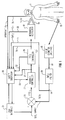
- Figure 1 illustrates in functional block diagram form a preferred embodiment of the present invention. A substantial portion of functions described below are actually carried out by the control system computer, which will be described later on with respect to the user interface. A
patient 8 requiring mechanical ventilation is connected to amechanical ventilator 10 via a breathing circuit 11. Breathing circuit 11 includes aninspiration line 12 by which ventilation gases are unidirectionally delivered topatient 8 and anexpiration line 14 for causing unidirectional flow of expired gases frompatient 8 tomechanical ventilator 10.Ventilator 10 may comprise any of several well known types of commercially available mechanical ventilators, such as the Model 900C manufactured by Siemens Corporation and available from Siemens Medical Systems, Iselin, NJ. Apulse oximeter 16 of conventional design includes anoptical sensor 18 coupled to the finger ofpatient 8 for non-invasively (e.g., optically) providing a measurement SpO₂, in a well known manner, of the blood oxygen saturation level ofpatient 8.Pulse oximeter 16 may be, for example, of the type manufactured by Siemens Corporation and comprise the Model 961 monitor system including a pulse oximeter cartridge unit therein.Pulse oximeter 16 includes an output for providing a high speed serial digital signal output SpO₂ representative of the measured SaO₂ level. - Before the measured SpO₂ level can be used for controlling the FIO₂, certain precautions must be taken. The present inventor has recognized the importance of providing artifact rejection filtering techniques to the measured SpO₂ level, in order to prevent erroneous operation of the FIO₂ feedback control system. That is, it is normal during the operation of a pulse oximeter, that artifact (false) output information will occasionally be generated in response to e.g., physical movement of
patient 8 and/or low profusion in the area ofsensor 18. This factor was noted in the forenoted Taube patent, however, responsive FIO₂ control was suspended during patient movement. However, in the present invention, an SpO₂ artifact filter 20 is provided for processing the output ofpulse oximeter 16. In the preferred embodiment, the function offilter 20 is provided completely by software processing in the control system microprocessor. An algorithm is used which rejects artifactual measurements of SpO₂ based on the statistics of past measurements of SpO₂. The algorithm replaces measured values of SpO₂ which fall substantially outside the variance of previous values of SpO₂ with pseudo values. These pseudo values are related to the average SpO₂ values and, in accordance with a further aspect of the present invention, the frequency of the artifactual SpO₂ values. As the frequency of artifacts increases the pseudo values are made increasingly less than the mean value, thereby causing the FIO₂ to be gradually increased. Thus, the algorithm provides an adaptive filtering of the SpO₂ values and gradual increase in the FIO₂, based on the frequency of the detected artifacts. Details offilter 20 will be described later on in conjunction with Figure 2. - After appropriate artifact rejection filtering, the SpO₂ value is then compared with a target SpO₂ value in a
comparator 21 and the difference signal E(t) (error) is then applied to afeedback controller module 22. The target SpO₂ value is provided by auser interface 24 which may comprise a personal computer of conventional design programmed in the C software language and which includes a keyboard, display, microprocessor and data storage means. The system user will input, via the keyboard, the desired set-point and limit values for the blood oxygen saturation levels as well as other patient data. The user interface display provides data to the physician informing him/her of the status of the system, the SpO₂ set-point, the measured SpO₂ and the measured FIO₂. -
Feedback controller 22 may comprise a PID (Proportional-Integral-Derivative) controller, such as described in greater detail later on.Feedback controller 22 receives the error signal provided bycomparator 21 and produces a stable control signal in response thereto, having a zero steady state error and limited overshoot. In a preferred embodiment of the invention, the proportional, integral and/or derivative terms are selectively controllable for adapting the response ofcontroller 22.Feedback controller 22 is also adaptive as a function of external input signals, such as minute ventilation (the amount of gas breathed by a patient in one minute). Additional novel features offeedback controller 22 will also be described later on relating to the periodic introduction of random FIO₂ level changes, which are used to adapt the response of the feedback compensation.Feedback controller 22 provides an output which indicates what the FIO₂ level should be, e.g., 30%. - An
FIO₂ controller 26, comprised partly of software and partly of hardware including a stepper motor, calculates the present set-point of the FIO₂ being delivered to the patient, compares this with the instructions received fromfeedback controller 22, and then mechanically controls a gas blender included inmechanical ventilator 10 for causing the FIO₂ level to be adjusted. The gas blender, not specifically shown, is a conventional part added to or built-in tomechanical ventilator 10 which controls the mixing of gas from an air source and an O₂ source, respectively, to the gas input ofventilator 10. For example, assume thatfeedback controller 22 provides an output (in software) toFIO₂ controller 26 demanding that the FIO₂ be increased to 30%. The software portion ofFIO₂ controller 26 will then calculate a number of pulses, e.g., 30 to the right, that must be applied to the stepper motor in order to cause the gas blender ofmechanical ventilator 10 to cause a 30% mixture between O₂ and air. This mechanical connection is indicated by the output fromcontroller 26 tomechanical ventilator 10, although an electronic control could also be used. - A final portion of the invention comprises
safety sub-system 28. A series of safety features are implemented in hardware and software which comprisesafety sub-system 28 to prevent hypoxic inspired mixtures and inadvertent errors in the operation of the FIO₂ control system. These include: - 1. Limit (threshold) values of SpO₂ and FIO₂ are entered into the system by the user via
interface 24.Safety sub-system 28 monitors the artifact corrected SpO₂ value vialine 29, the FIO₂ output fromcontroller 26 vialine 31, and the actual O₂ level sensed inventilator 10 andinspiration line 12 vialines sub-system 28 and cause visual and audible alerts to be directed to the physician. - 2. The system resets (see 4 below) based on missing signals from
pulse oximeter 16 orventilator 10. - 3. The system detects error between desired FIO₂ (i.e., the output from
controller 22 via line 37) and the measured FIO₂ at three different places. The first place is the output ofcontroller 26 vialine 31, the second place is the O₂ indication signal which is provided frommechanical ventilator 10, vialine 33 and the third place is a redundant O₂ indication signal provided from an O₂ sensor in breathing circuit 11, vialine 35. Each of these values should be correlated; if not, an alarm condition is indicated. - 4. The system automatically sets the output of
controllers controllers safety sub-system 28. - 5. All data is stored on magnetic media for retrospective analysis.
- Next, details of
artifact filter 20 will be described in conjunction with Figure 2. This filter algorithm is intended to handle artifacts in a safe, i.e. conservative, manner. Firstly, it recognizes that the pulse oximeter is artifact prone because it is sensitive to both patient movement and blood perfusion in the area ofsensor 18. Secondly, it assumes that when data is missing or suspiciously different (e.g., low) compared to the date immediately preceding it, it is probably artifactual. When artifacts are occurring, the worst scenario is that the SpO₂ is actually falling, and increasing the patient FIO₂ would be the appropriate therapy. Thus, when artifacts are occurring, we want to balance our concern that the SpO₂ may be falling with the knowledge that missing data is a routine occurrence. Furthermore, as the frequency of missing data increases, our concern that SpO₂ might be falling should also increase. Thus, in accordance with a further aspect of the present invention, when SpO₂ data is missing or suspiciously low (e.g., more than two standard deviations away from the mean of the previous values) we will initially assume the true SpO₂ value is likely to be the mean value. Additionally, in accordance with still a further aspect of the invention, to be conservative we will subtract an adaptive factor from the mean value to recognize the potential that the actual SpO₂ value may be falling. The factor is adaptively increased as the frequency of occurrence of the artifacts increases. This results in progressively increasing levels of FIO₂ for the patient to be set by the FIO₂ control system. - The artifact rejection algorithm of
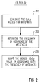
filter 20 is designed to insure that the FIO₂ control system operates normally. As artifacts occur, the control system will tend to increase FIO₂ gradually. Thus, as the frequency of artifacts increases, the controller will drive FIO₂ up harder. When the frequency of occurrence of the artifacts exceeds an intolerable limit, an alarm will sound and the controller will go open loop with FIO₂ = 100%. - As shown in Figure 2, filter 20 operates in accordance with the following process:
- Step 202:
- Evaluate the SpO₂ values for artifacts,
- Step 204:
- Determine the frequency of occurrence for the artifacts, and
- Step 206:
- Adapt the pseudo SpO₂ control value in accordance with the artifact occurrence frequency.
- This process is accomplished as follows:
- As shown in Figure 1, Sn = current SpO₂ value from
pulse oximeter 16. S'n = SpO₂ value sent tocomparator 21. - Sn-m , ..., Sn-3 , Sn-2 , Sn-1 , Sn is a series of m past SpO₂ output values.
- Compute a running average of Sn-m as:

- Compute a standard deviation of Sn-m as:

- Then, let Mn = a binary logical variable (possible artifact). We then set up four tests (windows) to determine if Mn is TRUE, i.e., an artifact, or FALSE, i.e., probably not an artifact but a good SpO₂ value from
oximeter 16. - 1. If Sn < (Sn - 2Sn) and Sn > 2 then Mn = TRUE
- 2. If Sn < (Sn - 4) and Sn ≦ 2 then Mn = TRUE
- 3. If Sn ≧ (Sn - 2Sn) and Sn > 2 then Mn = FALSE
- 4. If Sn ≧ (Sn - 4) and Sn ≦ 2 then Mn = FALSE
- As you can see from
tests -
Tests - Compute the frequency of artifact occurrences

for Mi where i = M-m to n-1 -
- 1. If Mn = FALSE then S'n = Sn
- 2. If Mn = TRUE then S'n = Sn - Q, where Q is one of q₁, q₂ or q₃.
Where,- Q =
- q₁ if 1/m < Fn ≦ fa;
- Q =
- q₂ if fa < Fn ≦ fb; and
- Q =
- q₃ if fb < Fn ≦ fc.
- 3. If Fn > fc then: a) ALARM, b) set FIO₂ = 100%; and c) set S'n = 0.5% (an arbitrary small, non-zero amount)
- 4. If Sn > 1/3 Sn then ALARM
- In the preferred embodiment, m = 10 sample SpO₂ values, fa = 3/10, fb = 5/10, fc = 6/10, and q₁ = 0.5%, q₂ = 1.0%, and q₃ = 2.0%.
-
Feedback controller 22 of the present invention is of the PID (Proportional-Integral-Derivative) controller type, and computes a feedback compensation response which is related to the difference between the desired (set-point) and measured SpO₂ values i.e., the output ofcomparator 21. The flow of the O₂ gas which is added to the breathing mixture of the patient is controlled by an electronic signal fromcontroller 22 which is used to adjust the stepper motor ofcontroller 26. The electronic signal is a function of the sum of three terms:
where Y(t) is the flow control signal, C₁, C₂ and C₃ are constants, E(t) is the Error (difference between the desired SpO₂ and the measured SpO₂ (S'n) and dE(t)/dt is the time derivative of E(t). The output Y(t) may be adjusted by a constant of proportionality as circumstance may dictate. - Although the above is an analog implementation of
feedback controller 22, it is also possible to use a sampled-data equivalent feedback controller, such as commonly used with microcomputers. The block diagram of a digital PID controller of the preferred embodiment is shown in Figure 3. The transfer function of the digital PID controller is as follows:
The microcomputer of the user interface system samples the input variable (E(t))periodically (every T seconds). Computer software is used to mathematically implement the feedback algorithm ofcontroller 22. - While the output of the digital controller is presented every T seconds, a circuit element called a zero-order-hold takes the periodically produced output e(t), holds it steady and implements the controlling output action.
- In the block diagram of the digital PID controller in Figure 3, K₃, K₂ and K₁ are coefficients (gain constants) of the proportional, integral and derivative terms, respectively. T is the sample time interval, n is an integer number of sample intervals. Z is the Z-transform operator, E(nT) is the error signal e(t) sampled every T seconds, and Y(nT) is the desired FIO₂ value. Note that K₃, K₂ and K₁ serve the same purpose as C₁, C₂ and C₃ in the analog implementation discussed previously; however, the values of K₁, K₂ and K₃ may be different from C₁, C₂ and C₃.
- A block diagram of this process is shown in Figure 4. The values of the coefficients as shown in Figure 4 are dependent on the characteristics of the design of the system which is being controlled. The increment (n), error (E), flow (F) and the output are functions of the volume and flow characteristics of the breathing circuit, the patient's lung and O₂ transfer characteristics, and the settings of the ventilator.
- It is also possible to use the patient's minute ventilation (MV), title volume (TV), and/or respiratory rate (RR) to modify one or more of the terms in the above circuit equation. The patient's minute ventilation, tidal volume, or respiratory rate may be measured using any of several well-known techniques. For example, these measurements may be based on thermal dissipation, a pressure difference across a resistive element (pneumotachograph), the rotation rate of a vane, or the oscillation frequency of a fluid vortex. This type of modification of the invention will be described next in greater detail with respect to Figure 6. Furthermore, in accordance with another aspect of the invention, design goals such as tolerable overshoot, time to achieve control and accuracy of control are also used to determine the value of coefficients K₁, K₂ and K₃. Details relating to modifications of this type are described in greater detail with respect to Figure 7.
- First, however, the initial set-up of
controller 22 will be described. Referring to the above equation for the transfer function of the digital PID controller, the values of K₁, K₂ or K₃, or any selective combination of K₁, K₂ and K₃ are adjusted as a function of the error signal e(t), i.e., the output ofcomparator 21. The initial set-up of these values is accomplished in order to tailor the response of the FIO₂ control system in accordance with the clinical goals for given classes of patients. For example, there may be a first set of values for K₁, K₂, K₃ for adults and a second set of K values for neonatal patients. - In accordance with a further aspect of the invention, these K values of the PID controller are made non-linear in order to more appropriately tailor the response of the FIO₂ system in accordance with empirically determined desired values for specific classes of patients. Additionally, it is noted that the non-linear gain provided by
PID controller 22 makes the response of the FIO₂ control loop more clinically appropriate. For example, Figure 5(a) illustrates a value for K₁ as a function of e(t). However, a limiting value is provided so that the integrator term does not get to large. Although the previously noted U.S. Patent 4,889,116 to Taube includes a PID controller, it is noted that no individual control of the proportional or integral or derivative terms is provided, such as specifically provided by the present invention. - Figure 5(b) illustrates an additional non-linear characteristics for the K values, which was used for the K₃ value specifically in the preferred embodiment of the present invention and Figure 5(c) is an alternative embodiment thereof. Thus, it is apparent from these figures that non-linear coefficients are provided for various ones of the terms of the PID controller which change in real time in accordance with the error signal provided at the output of
comparator 21. - Additionally, it is noted that limiting values are also imposed upon the output of PID controller, as previously noted, which prevent the output FIO₂ values from being greater than 100% or less than 0%.
- Figure 6(a) is illustrative of the way in which external inputs can be applied to control the coefficients of
PID controller 22 in order to change the system response accordingly. The external inputs may comprise the minute ventilation (MV), the respiratory rate (RR) and/or the tidal volume (TV). For example, K₁ could be a function of minute ventilation or K₁, K₂, K₃ could be functions of RR, MV and TV, respectively. In fact, any combination of functional relationships between the K's and external inputs are possible. In the preferred embodiment, the value of K₃ is changed in response to the minute ventilation as shown in Figure 6(b). - A final control of the characteristics for
controller 22 relates to an adaptiveness of its response to the changing needs of the patient. In this regard, it is noted that in the forenoted Taube U.S. Patent 4,889,116, the controller program described in Exhibit A initially asks the user to input a "lung time constant tl". The present inventor has recognized that the initial values of k which determine the controller response may not be appropriate during later periods of the ventilation therapy for the patient. In accordance with a further feature of the invention, the PID controller output is periodically and randomly varied (within prescribed safety limits) in order to adapt the responsiveness ofcontroller 22 with the changing needs of the patient. - Figure 7(a) illustrates a functional block diagram of the FIO₂ control loop including a Recursive Least Squares (RLS) computation used for modifying the response of
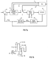
controller 22. When software switch A is in position one, the RLS algorithm 700 is dormant. Under these conditions, the values for the gains of the PID feedback compensation (K₁, K₂ and K₃) are set at their initial (default) values. - When RLS algorithm 700 is activated, switch A is in position two, and a sequence of random magnitude FIO₂ values are applied to the blender of
ventilator 10 via line B. The sequence of random FIO₂ values are a percentage (±) of a predetermined FIO₂ value. The predetermined value is the last value of FIO₂ before the RLS algorithm was started (which is input to RLS algorithm 700 via line C). The initial value may also be an average of several previous FIO₂ values in order to eliminate the possibility that the last FIO₂ value is non-representative of the actual needs of the patient. - Figure 7(b) illustrates an example of what one such random sequence might look like. The random 10 second periods of FIO₂ ±m% occur approximately 20 to 60 times each 15 minutes, in the preferred embodiment. The range of amplitudes of m is set by clinical considerations and performance issues. A range of m equal to 10%, 15% and 20% has been used.
- The response of the patient as measured by
pulse oximeter 16 is input to RLS algorithm 700 via line D for processing. When the RLS algorithm has collected several values, in the preferred embodiment 30, it begins to process these values in accordance with the Recursive Least Squares (RLS) computation, such as known by those skilled in the art, and described for example in "Dynamic System Identification: Experiment, Design and Data Analysis" by Graham C. Goodwin and Robert L. Payne, Academic press, New York, 1977; and an article entitled "Digital Parameter-Adaptive Control of Processes with Unknown Dead Time" by Kurz et al. in Automatica, Vol. 17, No. 1, pp. 245-252, 1981, published by Permagon Press; and as also described in conjunction with control of arterial blood pressure in an article entitled "The Self-Tuning Controller: Comparison with Human Performance in the Control of Arterial Pressure" by Kenneth S. Stern et al., published in the Annals of Biomedical Engineering. - Briefly, what the RLS algorithm does is find a set of coefficients (a's and b's) of a linear combination of past and present FIO₂ values and past SpO₂ values for determining an estimated SpO₂ value, which set of coefficients minimizes the mean square difference between this estimated value of SpO₂ and the actually measured value of SpO₂. When values for a and b are obtained which cause the computed and measured values to be substantially equal, it can be said that the RLS algorithm has converged. If 30 samples of SpO₂ at 10 second intervals was not enough to cause convergence, the RLS algorithm will continue acquiring new SpO₂ values while dropping the oldest SpO₂ values and then try to converge. Upon convergence, new values may be found for the time constant (T) and time delay (L) of the controller response, which leads to new values for the K₁, K₂, and K₃, coefficients, respectively. These new coefficients are coupled to
controller 22 via line K. A more detailed description of the theory and process for accomplishing the RLS algorithm is described in greater detail in Exhibit A. - Thus, there has been shown and described a novel method and apparatus for controlling the amount of oxygen inspired by a patient. Many changes, modifications, variations and other uses and applications of the subject invention will, however, become apparent to those skilled in the art after considering this specification and the accompanying drawings, which disclose a preferred embodiment thereof. For example, the PID controller of the present invention could in fact be a PI controller or some other type of controller having adjustable response characteristics. Furthermore the feedback control loop could be integrated into the
ventilator 10 orpulse oximeter 16. All such changes, modifications, variations and other uses and applications of the invention are deemed to be covered by the claims which follow.
Claims (32)
- An adaptive controller for delivering a fractional amount of oxygen to a patient, said controller comprising:
oximeter means coupled by a non-invasive sensor to said patient for measuring blood hemoglobin saturation in the patient, said oximeter generating a plurality of blood saturation output signal values over a given period of time, sequentially representative of said blood hemoglobin saturation;
processing means responsive to said blood saturation output signal for evaluating a plurality of said output signal values and, based on said evaluation, providing a processed output signal; and
feedback control means continuously responsive to said processed output signal for determining the fractional amount of oxygen to be delivered to the patient. - The adaptive controller of claim 1 wherein said oximeter is a pulse oximeter and said plurality of blood saturation output signal values are oxygen saturation of hemoglobin values as measured by a pulse oximeter (SpO₂ values).
- The adaptive controller of claim 1 wherein said processing means includes:
artifact recognition means for identifying possibly invalid output signal values and for providing a sequence of valid output signal values, exclusive of said identified possibly invalid output signal values; and
means for generating a running average of said sequence of valid output signal values and for providing said running average as said processed output signal; - The adaptive controller of claim 3 wherein said artifact recognition means includes means for comparing each of said plurality of output signal values to said running average and for identifying as possibly invalid any output signal value which differs from said running average by more than a predetermined amount.
- The adaptive controller of claim 3 wherein the artifact recognition means further includes means for substituting respective pseudo output signal values for each of said identified possibly invalid output signal values to generate said sequence of valid output signal values, wherein the value of said pseudo output signal values is a function of said running average of said oximeter means output signal values.
- The adaptive controller of claim 5 wherein said processing means further includes:
monitoring means, coupled to said artifact recognition means, for determining the frequency of occurrence of said possibly invalid output signal values; and
means, coupled to said monitoring means, for decreasing the value of said pseudo output signal values in proportion to the frequency of occurrence of said possibly invalid output signal values to condition the feedback control means to gradually increase the fractional amount of oxygen to be delivered to the patient. - The adaptive controller of claim 3 wherein said means for generating said running average includes means for calculating a mean value and a standard deviation value for m of said plurality of valid output signal values most recently provided by said artifact recognition means, where m is an integer, and for providing said calculated mean value as said processed output signal.
- The adaptive controller of claim 7 wherein said artifact recognition means includes means for comparing each of said plurality of output signal values to said mean value and for identifying as possibly invalid any output signal value which differs from said mean value by an amount greater than two times said standard deviation value.
- The adaptive controller of claim 7 wherein the feedback control means includes:
means for generating a difference signal having a value which represents the difference between the processed output signal and a value representing a desired blood hemoglobin saturation value; and
means, responsive to said difference signal, for changing the fractional amount of oxygen delivered to the patient in a sense which tends to reduce the value of said difference signal. - The adaptive controller of claim 9 wherein the means for changing the fractional amount of oxygen delivered to the patient includes a proportional-integral-derivative controller.
- An adaptive controller for delivering a fractional amount of oxygen to a patient, said controller comprising:
measuring means, adapted to be coupled to the patient, for measuring blood oxygen level in the patient and for providing a plurality of output signal values, sequentially representative of said measured blood oxygen level;
processing means, coupled to said measuring means, for generating a running average of said plurality of output signal values and for subtracting said running average from a target value, representing a desired blood oxygen level for the patient, to produce a difference signal;
feedback control means, coupled to receive said difference signal, for adjusting the fractional amount of oxygen to be delivered to the patient to minimize said difference signal in magnitude. - The adaptive controller of claim 11 wherein the feedback controller is defined by a transfer function, having a plurality of adjustable coefficients, which establishes how the fractional amount of oxygen delivered to the patient is to be changed, both in time and in magnitude, in response to a change in the difference signal.
- The adaptive controller of claim 12, further including:
means for measuring a plurality of physiological parameters related to respiration to produce a respective plurality of output signals; and
adjustment means responsive to said plurality of output signals for adaptively changing the values of said coefficient values to change the transfer function of said feedback controller. - The adaptive controller of claim 13 wherein said physiological parameters include one or more of minute ventilation, respiratory rate and tidal volume; and
said adjustment means includes means for automatically adjusting said coefficient values as a function of said plurality of output signals. - The adaptive controller of claim 12 further including means for periodically and automatically varying the coefficient values to change the transfer function of the feedback controller to track changing needs of the patient.
- The adaptive controller of claim 15 wherein the means for periodically and automatically varying the coefficient values includes:
means for randomly changing the fractional amount of oxygen to be delivered to the patient within predetermined minimum and maximum limiting values; and
coefficient adapting means, responsive to the respective measured blood oxygen level values resulting from the changes in the fractional amount of oxygen, for adjusting the coefficient values to match the response of the control system to the response of the patient. - The adaptive controller of claim 16 wherein the coefficient adapting means includes:
means for recording the random sequence of changes in fractional amount of oxygen delivered to the patient and the respective measured blood oxygen levels resulting from the sequence of changes in the fractional amount of oxygen;
means for calculating, based on the recorded changes in the fractional amount of oxygen, the recorded blood oxygen levels and the transfer function of the feedback controller, an expected present blood oxygen level; and
means for repeatedly changing the coefficient values and recalculating the expected present blood oxygen level to minimize any difference in magnitude between the expected present blood oxygen level and the measured blood oxygen level currently provided by the measuring means. - The adaptive controller of claim 17 wherein the means for repeatedly changing the coefficient values includes means for evaluating the recorded changes in the fractional amount of oxygen, the recorded blood oxygen levels and the transfer function of the feedback controller according to a recursive least squares optimization method.
- The adaptive controller of claim 12 wherein the feedback controller is a proportional-integral-derivative (PID) controller.
- The adaptive controller of claim 19 wherein the transfer function, Y(nT)/E(nT), defining the feedback controller is given by an equation:

where K₃, K₂ and K₁ are respective proportional, integral and derivative coefficient values, Z is the Z-transform operator, T is a sampling interval in seconds, n is the number of current sample values, Y(nT) is the current output value and E(nT) is the current value of the difference signal. - In a system for automatically providing a controlled fractional amount of oxygen to a patient, including an oximeter for measuring blood oxygen levels of the patient and a feedback controller, coupled to the oximeter for adjusting the fractional amount of oxygen delivered to the patient to maintain the measured blood oxygen levels within predetermined limits, a safety subsystem to prevent the system from erroneously administering a hypoxic mixture, said safety subsystem comprising:
means for measuring the fractional amount of oxygen being delivered to the patient and for providing a signal indicative thereof;
means for correlating the measured fractional amount of oxygen to a preferred fractional amount of oxygen as determined by the feedback control system and for producing an alarm signal when the measured and preferred fractional amounts of oxygen are determined to be uncorrelated;
means, responsive to said alarm signal, for adjusting the fractional amount of oxygen to be delivered to the patient to a maximum value. - The safety subsystem of claim 21, wherein:
the means for measuring the fractional amount of oxygen delivered to the patient includes means for sensing the oxygen level of the air being provided to the patient using a plurality of sensors; and
the correlating means includes means for correlating the preferred fractional amount of oxygen to each of the plurality of sensed oxygen levels and for generating said alarm signal if any of the sensed oxygen levels is not correlated to said preferred fractional amount of oxygen. - The safety subsystem of claim 21, further comprising:
first monitoring means for detecting errors in the blood oxygen level signal provided by said oximeter;
second monitoring means for detecting errors in the signal provided by said means for measuring the fractional amount of oxygen being delivered to the patient; and
means for generating said alarm signal in response to an error being detected by one of said first and second monitoring means. - The safety subsystem of claim 23 wherein said first and second monitoring means detect missing values of said respective blood oxygen level signal and said measured fractional amount of oxygen signal as the errors in the respective signals.
- The safety subsystem of claim 21 wherein said feedback controller includes:
means for monitoring the blood oxygen level signals provided by the oximeter to identify possibly invalid signal values and to provide a sequence of valid signal values, exclusive of said identified possibly invalid signal values; and
said safety system further includes:
means for setting a first threshold value representing a minimum desirable level of said blood oxygen level signal and a second threshold value representing a minimum desirable level of said preferred fractional amount of oxygen and said measured fractional amount of oxygen; and
means for producing said alarm signal when one of said sequence of valid signal values is less than said first threshold value;
means for producing said alarm signal when one of said preferred fractional amount of oxygen and said measured fractional amount of oxygen is less than said second threshold value. - The safety subsystem of claim 21 further comprising, non-volatile memory means for storing the measured blood oxygen level values provided by said oximeter and the measured fractional amount of oxygen being delivered to the patient.
- The safety subsystem of claim 26 wherein values representing said preferred fractional amount of oxygen are stored in said non-volatile memory means.
- A method for adaptively controlling the fractional amount of oxygen delivered to a patient comprising the steps of:a) measuring the blood hemoglobin saturation in the patient during a plurality of intervals over a given period of time and providing said measured values as an output signal;b) evaluating each of the measured values of said output signal to identify possibly invalid output signal values;c) eliminating said identified possibly invalid output signal values from said output signal to produce a processed output signal;d) adjusting the fractional amount of oxygen delivered to the patient in a sense to minimize any difference between said processed output signal and a predetermined desired blood hemoglobin saturation signal.
- The method of claim 28 wherein the step c) includes the steps of:c1) generating a sequence of valid output signal values by substituting a pseudo value for each of said identified possibly invalid output signal values;c2) generating a running average of successive values of said sequence of valid output signal values, wherein the instantaneous value of said running average is said pseudo value; andc3) providing said running average as said processed output signal.
- The method of claim 29 wherein step c1) includes the steps of:
monitoring the frequency of occurrence of said identified possibly invalid output signal values; and
decreasing the value of said substituted pseudo values in proportion to the frequency of occurrence of said identified possibly invalid output signal values. - A method of adapting an automatic controller which delivers a controlled fractional amount of oxygen to a patient to maintain a measured blood oxygen level at a value which approximates a preferred blood oxygen level, wherein the controller operates in accordance with a transfer function having variable coefficient values, said method comprising the steps of:a) changing the fractional amount of oxygen delivered to the patient within predetermined minimum and maximum limiting values in accordance with a pseudo-random sequence;b) measuring the blood oxygen level of the patient resulting from each change in the fractional amount of oxygen delivered to the patient including a final blood oxygen level resulting from a final fractional amount of oxygen in the pseudo-random sequence;c) recording a sequence of values representing the fractional amounts of oxygen provided in step a) and the respective measured blood oxygen levels obtained in step b);d) calculating, based on the recorded fractional amounts of oxygen, the recorded blood oxygen levels, exclusive of said final blood oxygen level, and the transfer function, an expected final blood oxygen level;e) repeatedly changing the coefficient values and repeating step d) to minimize any difference in magnitude between the expected final blood oxygen level and the recorded final blood oxygen level.
- The method of claim 31 wherein step e) includes the steps of changing the coefficient values and repeating step d) in accordance with a recursive least squares optimization method.
Applications Claiming Priority (2)
| Application Number | Priority Date | Filing Date | Title |
|---|---|---|---|
| US671586 | 1991-03-19 | ||
| US07/671,586 US5365922A (en) | 1991-03-19 | 1991-03-19 | Closed-loop non-invasive oxygen saturation control system |
Publications (2)
| Publication Number | Publication Date |
|---|---|
| EP0504725A2 true EP0504725A2 (en) | 1992-09-23 |
| EP0504725A3 EP0504725A3 (en) | 1993-10-27 |
Family
ID=24695123
Family Applications (1)
| Application Number | Title | Priority Date | Filing Date |
|---|---|---|---|
| EP19920104185 Withdrawn EP0504725A3 (en) | 1991-03-19 | 1992-03-11 | Closed-loop non-invasive oxygen saturation control system |
Country Status (3)
| Country | Link |
|---|---|
| US (1) | US5365922A (en) |
| EP (1) | EP0504725A3 (en) |
| JP (1) | JPH06105912A (en) |
Cited By (24)
| Publication number | Priority date | Publication date | Assignee | Title |
|---|---|---|---|---|
| EP0580385A1 (en) * | 1992-07-21 | 1994-01-26 | Archibald Ian Jeremy Dr. Brain | Laryngeal mask incorporating a reflectance oximeter |
| WO1995032016A1 (en) * | 1994-05-20 | 1995-11-30 | Puritan-Bennett Corporation | System for optimizing continuous positive airway pressure for treatment of obstructive sleep apnea |
| US5752509A (en) * | 1995-07-10 | 1998-05-19 | Burkhard Lachmann | Artificial ventilation system |
| EP0870465A1 (en) * | 1997-04-12 | 1998-10-14 | Hewlett-Packard Company | Method and apparatus for the non-invasive determination of the concentration of a component |
| WO2001000265A1 (en) * | 1999-06-30 | 2001-01-04 | University Of Florida | Medical ventilator and method of controlling same |
| FR2801794A1 (en) * | 1999-12-02 | 2001-06-08 | Hospal Ag | METHOD FOR DETERMINING A SIGNIFICANT PARAMETER OF THE PROGRESS OF AN EXTRACORPOREAL BLOOD TREATMENT |
| US6691040B2 (en) | 1999-12-02 | 2004-02-10 | Hospal Ag | Method for determining a parameter indicative of the progress of an extracorporeal blood treatment |
| EP1579883A2 (en) * | 1997-07-25 | 2005-09-28 | Minnesota Innovative Technologies & Instruments Corporation (MITI) | Control device for supplying supplemental respiratory oxygen |
| WO2006127356A2 (en) | 2005-05-24 | 2006-11-30 | Versamed, Inc. | Apparatus and method for controlling fraction of inspired oxygen |
| WO2007085110A1 (en) * | 2006-01-30 | 2007-08-02 | Hamilton Medical Ag | O2-controller |
| WO2008036213A2 (en) * | 2006-09-20 | 2008-03-27 | Nellcor Puritan Bennett Llc | Method and system for circulatory delay compensation in closed-loop control of a medical device |
| WO2008043724A2 (en) * | 2006-10-12 | 2008-04-17 | Dynamic Therapeutics Ltd | Regulated drug delivery system |
| WO2009120607A1 (en) * | 2008-03-27 | 2009-10-01 | Nellcor Puritan Bennett Llc | Method for controlling delivery of breathing gas to a patient using multiple ventilaton parameters |
| WO2010093677A2 (en) * | 2009-02-12 | 2010-08-19 | Oregon Health & Science University | Method and apparatus for prevention of apnea |
| WO2010101778A1 (en) * | 2009-03-06 | 2010-09-10 | Cardinal Health 207, Inc. | Automated oxygen delivery system |
| US7992557B2 (en) | 1999-02-12 | 2011-08-09 | Covidien Ag | Gas supply device for sleep apnea |
| US8302602B2 (en) | 2008-09-30 | 2012-11-06 | Nellcor Puritan Bennett Llc | Breathing assistance system with multiple pressure sensors |
| EP2575617A1 (en) * | 2010-05-26 | 2013-04-10 | The Curators Of The University Of Missouri | Closed loop respiratory support device with dynamic adaptability |
| WO2013127400A1 (en) * | 2012-03-02 | 2013-09-06 | Mermaid Care A/S | Method for calibrating the level of oxygen in respiratory gas related to the level of oxygen in the blood circulation of an individual |
| US8528552B2 (en) | 2008-12-01 | 2013-09-10 | Dräger Medical GmbH | SPO2 control with adaptive linear compensation |
| US8573206B2 (en) | 1994-09-12 | 2013-11-05 | Covidien Lp | Pressure-controlled breathing aid |
| WO2014041103A1 (en) * | 2012-09-12 | 2014-03-20 | Maquet Critical Care Ab | An anesthesia system, a method and a computer-readable medium for actively controlling oxygen delivered to a patient |
| RU2728185C2 (en) * | 2015-11-10 | 2020-07-28 | Юниверсити Оф Тасмания | Method, device and system for automatic control of oxygen supply |
| CN113082412A (en) * | 2021-03-30 | 2021-07-09 | 湖南万脉医疗科技有限公司 | Method and system for controlling oxygen concentration fraction of inhaled gas of breathing machine |
Families Citing this family (105)
| Publication number | Priority date | Publication date | Assignee | Title |
|---|---|---|---|---|
| GB9103419D0 (en) * | 1991-02-19 | 1991-04-03 | Univ Manitoba | Piston-based ventilator design and operation |
| US5682877A (en) * | 1991-12-30 | 1997-11-04 | Mondry; Adolph J. | System and method for automatically maintaining a blood oxygen saturation level |
| SE9500275L (en) * | 1995-01-26 | 1996-07-27 | Siemens Elema Ab | Method and apparatus for determining a transfer function for a connection system |
| SE9502031D0 (en) * | 1995-06-02 | 1995-06-02 | Lachmann Burkhard | Arrangement and method for determining an optimal opening pressure in a lung system |
| US5671734A (en) * | 1995-11-03 | 1997-09-30 | The United States Of America As Represented By The Secretary Of The Navy | Automatic medical sign monitor |
| US5865174A (en) * | 1996-10-29 | 1999-02-02 | The Scott Fetzer Company | Supplemental oxygen delivery apparatus and method |
| US5915379A (en) | 1997-03-14 | 1999-06-29 | Nellcor Puritan Bennett Incorporated | Graphic user interface for a patient ventilator |
| US5865168A (en) * | 1997-03-14 | 1999-02-02 | Nellcor Puritan Bennett Incorporated | System and method for transient response and accuracy enhancement for sensors with known transfer characteristics |
| US6532958B1 (en) | 1997-07-25 | 2003-03-18 | Minnesota Innovative Technologies & Instruments Corporation | Automated control and conservation of supplemental respiratory oxygen |
| US6371114B1 (en) | 1998-07-24 | 2002-04-16 | Minnesota Innovative Technologies & Instruments Corporation | Control device for supplying supplemental respiratory oxygen |
| US6142149A (en) * | 1997-10-23 | 2000-11-07 | Steen; Scot Kenneth | Oximetry device, open oxygen delivery system oximetry device and method of controlling oxygen saturation |
| WO2000016839A1 (en) * | 1998-09-23 | 2000-03-30 | The Johns Hopkins University | Emergency life support system |
| FI982652A (en) * | 1998-12-08 | 2000-06-09 | Instrumentarium Oyj | Arrangement in connection with the equipment used in patient care |
| FI110065B (en) * | 1998-12-08 | 2002-11-29 | Instrumentarium Oyj | Device in a feedback control system |
| ATE401038T1 (en) * | 1999-02-03 | 2008-08-15 | Mermaid Care As | AUTOMATIC LUNG PARAMETERS ESTIMATION |
| US6962155B1 (en) * | 1999-07-30 | 2005-11-08 | Universite De Montreal | Target drive ventilation gain controller and method |
| US6192883B1 (en) | 1999-08-03 | 2001-02-27 | Richard L. Miller, Jr. | Oxygen flow control system and method |
| US6694969B1 (en) * | 1999-09-22 | 2004-02-24 | Instrumentarium Corp. | Method to improve oxygenation in subjects suffering impaired oxygenation |
| US6470885B1 (en) | 2000-01-13 | 2002-10-29 | Brent Blue | Method and apparatus for providing and controlling oxygen supply |
| US20020195105A1 (en) * | 2000-01-13 | 2002-12-26 | Brent Blue | Method and apparatus for providing and controlling oxygen supply |
| US6761165B2 (en) | 2000-02-29 | 2004-07-13 | The Uab Research Foundation | Medical ventilator system |
| US6938619B1 (en) | 2000-06-13 | 2005-09-06 | Scott Laboratories, Inc. | Mask free delivery of oxygen and ventilatory monitoring |
| US6651658B1 (en) * | 2000-08-03 | 2003-11-25 | Sequal Technologies, Inc. | Portable oxygen concentration system and method of using the same |
| US6557553B1 (en) | 2000-09-05 | 2003-05-06 | Mallinckrodt, Inc. | Adaptive inverse control of pressure based ventilation |
| US6512938B2 (en) * | 2000-12-12 | 2003-01-28 | Nelson R. Claure | System and method for closed loop controlled inspired oxygen concentration |
| IL140977A0 (en) | 2001-01-18 | 2002-02-10 | Automed Automatic Dosage Syste | Automatically regulating oxygen flow to a patient |
| CA2489808C (en) | 2002-06-20 | 2016-04-19 | Richard Melker | Perfusion monitor and system, including specifically configured oximeter probes and covers for oximeter probes |
| US7246620B2 (en) * | 2003-04-21 | 2007-07-24 | Conroy Jr John D | System for monitoring pilot and/or passenger oxygen saturation levels and estimating oxygen usage requirements |
| US20040206352A1 (en) * | 2003-04-21 | 2004-10-21 | Conroy John D. | System and method for monitoring passenger oxygen saturation levels and estimating oxygen usage requirements |
| US7588033B2 (en) | 2003-06-18 | 2009-09-15 | Breathe Technologies, Inc. | Methods, systems and devices for improving ventilation in a lung area |
| US7383105B2 (en) * | 2003-10-30 | 2008-06-03 | Conroy Jr John D | System and method for monitoring passenger oxygen saturation levels and estimating oxygen usage requirements |
| US7802571B2 (en) * | 2003-11-21 | 2010-09-28 | Tehrani Fleur T | Method and apparatus for controlling a ventilator |
| US7222624B2 (en) * | 2004-07-02 | 2007-05-29 | Praxair Technology, Inc. | Dual sensor oxygen therapy device |
| US7013898B2 (en) | 2004-07-09 | 2006-03-21 | Praxair Technology, Inc. | Nasal pressure sensor oxygen therapy device |
| ITMI20050866A1 (en) | 2005-05-13 | 2006-11-14 | Marco Ranucci | MONITORING SYSTEM FOR CARDIAC SURGERY INTERVENTIONS WITH CARDIOPOLMONARY BYPASS |
| NZ552009A (en) * | 2006-01-24 | 2007-10-26 | Devx Tech Ip Ltd | Hypoxic training apparatus with gas supply from primary, secondary and tertiary sources |
| EP1984050B1 (en) * | 2006-01-30 | 2010-10-13 | Hamilton Medical AG | An apparatus for regulating a mechanical ventilation |
| WO2007095154A2 (en) * | 2006-02-10 | 2007-08-23 | The Brigham And Women's Hospital, Inc. | Lectin complement pathway assays and related compositions and methods |
| US8021310B2 (en) | 2006-04-21 | 2011-09-20 | Nellcor Puritan Bennett Llc | Work of breathing display for a ventilation system |
| US8667963B2 (en) * | 2006-05-16 | 2014-03-11 | Impact Instrumentation, Inc. | Ventilator circuit for oxygen generating system |
| EP2023987B1 (en) | 2006-05-18 | 2016-11-09 | Breathe Technologies, Inc. | Tracheotomy device |
| US7784461B2 (en) | 2006-09-26 | 2010-08-31 | Nellcor Puritan Bennett Llc | Three-dimensional waveform display for a breathing assistance system |
| US8728059B2 (en) | 2006-09-29 | 2014-05-20 | Covidien Lp | System and method for assuring validity of monitoring parameter in combination with a therapeutic device |
| US8695593B2 (en) * | 2007-03-31 | 2014-04-15 | Fleur T. Tehrani | Weaning and decision support system for mechanical ventilation |
| US7983542B2 (en) * | 2007-10-29 | 2011-07-19 | Smiths Medical Asd, Inc. | PID coefficient adjustment for respiratory heater closed loop control |
| US20090133695A1 (en) * | 2007-11-27 | 2009-05-28 | Rao Chamkurkishtiah P | Mechanical ventilator system |
| US8423381B2 (en) * | 2008-03-17 | 2013-04-16 | Koninklijke Philips Electronics N.V. | Patient monitor with integrated closed loop controller |
| WO2009115948A1 (en) * | 2008-03-17 | 2009-09-24 | Philips Intellectual Property & Standards Gmbh | A closed loop system for automatically controlling a physiological variable of a patient |
| US8640700B2 (en) * | 2008-03-27 | 2014-02-04 | Covidien Lp | Method for selecting target settings in a medical device |
| EP2313138B1 (en) | 2008-03-31 | 2018-09-12 | Covidien LP | System and method for determining ventilator leakage during stable periods within a breath |
| US8272380B2 (en) | 2008-03-31 | 2012-09-25 | Nellcor Puritan Bennett, Llc | Leak-compensated pressure triggering in medical ventilators |
| US8267085B2 (en) | 2009-03-20 | 2012-09-18 | Nellcor Puritan Bennett Llc | Leak-compensated proportional assist ventilation |
| US8746248B2 (en) | 2008-03-31 | 2014-06-10 | Covidien Lp | Determination of patient circuit disconnect in leak-compensated ventilatory support |
| US8457706B2 (en) | 2008-05-16 | 2013-06-04 | Covidien Lp | Estimation of a physiological parameter using a neural network |
| US20090320836A1 (en) * | 2008-06-30 | 2009-12-31 | Baker Jr Clark R | Method For Regulating Treatment Based On A Medical Device Under Closed-Loop Physiologic Control |
| US8551006B2 (en) | 2008-09-17 | 2013-10-08 | Covidien Lp | Method for determining hemodynamic effects |
| US8428672B2 (en) * | 2009-01-29 | 2013-04-23 | Impact Instrumentation, Inc. | Medical ventilator with autonomous control of oxygenation |
| US8424521B2 (en) | 2009-02-27 | 2013-04-23 | Covidien Lp | Leak-compensated respiratory mechanics estimation in medical ventilators |
| US8434479B2 (en) | 2009-02-27 | 2013-05-07 | Covidien Lp | Flow rate compensation for transient thermal response of hot-wire anemometers |
| US8418691B2 (en) | 2009-03-20 | 2013-04-16 | Covidien Lp | Leak-compensated pressure regulated volume control ventilation |
| US8378832B2 (en) * | 2009-07-09 | 2013-02-19 | Harry J. Cassidy | Breathing disorder treatment system and method |
| US9364623B2 (en) * | 2009-07-15 | 2016-06-14 | UNIVERSITé LAVAL | Method and device for administering oxygen to a patient and monitoring the patient |
| US8789529B2 (en) | 2009-08-20 | 2014-07-29 | Covidien Lp | Method for ventilation |
| US8924878B2 (en) | 2009-12-04 | 2014-12-30 | Covidien Lp | Display and access to settings on a ventilator graphical user interface |
| US9119925B2 (en) | 2009-12-04 | 2015-09-01 | Covidien Lp | Quick initiation of respiratory support via a ventilator user interface |
| US8335992B2 (en) | 2009-12-04 | 2012-12-18 | Nellcor Puritan Bennett Llc | Visual indication of settings changes on a ventilator graphical user interface |
| US9262588B2 (en) | 2009-12-18 | 2016-02-16 | Covidien Lp | Display of respiratory data graphs on a ventilator graphical user interface |
| US8499252B2 (en) | 2009-12-18 | 2013-07-30 | Covidien Lp | Display of respiratory data graphs on a ventilator graphical user interface |
| US8676285B2 (en) | 2010-07-28 | 2014-03-18 | Covidien Lp | Methods for validating patient identity |
| US9352109B2 (en) * | 2010-08-02 | 2016-05-31 | Koninklijke Philips N.V. | Method for semantic communication of device data between a source and receiving client |
| WO2012024342A1 (en) * | 2010-08-16 | 2012-02-23 | Breathe Technologies, Inc. | Methods, systems and devices using lox to provide ventilatory support |
| US8554298B2 (en) | 2010-09-21 | 2013-10-08 | Cividien LP | Medical ventilator with integrated oximeter data |
| US8939152B2 (en) | 2010-09-30 | 2015-01-27 | Breathe Technologies, Inc. | Methods, systems and devices for humidifying a respiratory tract |
| BR112013014920A2 (en) * | 2010-12-17 | 2016-09-13 | Koninkl Philips Electronics Nv | system configured to control an oxygen fraction inspired by a pressurized flow of breathable gas released into a patient's lungs |
| US8511651B2 (en) | 2011-03-29 | 2013-08-20 | Smiths Medical Asd, Inc. | Heater unit humidification chamber monitor |
| WO2013027151A1 (en) * | 2011-08-25 | 2013-02-28 | Koninklijke Philips Electronics N.V. | Method and apparatus for controlling a ventilation therapy device |
| US9089657B2 (en) | 2011-10-31 | 2015-07-28 | Covidien Lp | Methods and systems for gating user initiated increases in oxygen concentration during ventilation |
| US9254368B2 (en) | 2011-12-02 | 2016-02-09 | Drägerwerk AG & Co. KGaA | Oxygen regulation with at least two SPO2 monitors and automatic recognition of a signal having a higher rating |
| GB2569467B (en) | 2012-04-05 | 2019-10-30 | Fisher & Paykel Healthcare Ltd | Respiratory assistance apparatus |
| US9993604B2 (en) | 2012-04-27 | 2018-06-12 | Covidien Lp | Methods and systems for an optimized proportional assist ventilation |
| EP3744377A1 (en) * | 2012-05-02 | 2020-12-02 | Fisher & Paykel Healthcare Limited | Respiratory humidifier communication systems |
| US10362967B2 (en) | 2012-07-09 | 2019-07-30 | Covidien Lp | Systems and methods for missed breath detection and indication |
| MX369310B (en) * | 2013-01-29 | 2019-11-05 | Koninklijke Philips Nv | Control of neonatal oxygen supply. |
| US9675771B2 (en) | 2013-10-18 | 2017-06-13 | Covidien Lp | Methods and systems for leak estimation |
| US11291868B2 (en) * | 2013-12-20 | 2022-04-05 | B/E Aerospace, Inc. | Pulse saturation oxygen delivery system and method |
| US10869987B2 (en) * | 2013-12-20 | 2020-12-22 | B/E Aerospace, Inc | Pulse saturation oxygen delivery system and method |
| US20150217056A1 (en) * | 2013-12-31 | 2015-08-06 | Stratos Group Llc | Therapy systems and methods utilizing tissue oxygenation detection |
| EP4235120A3 (en) | 2014-05-27 | 2023-10-04 | Fisher & Paykel Healthcare Limited | Gases mixing and measuring for a medical device |
| EP2985050A1 (en) | 2014-08-12 | 2016-02-17 | Linde Aktiengesellschaft | Method of upgrading clinical oxygen supply arrangement |
| US9130559B1 (en) * | 2014-09-24 | 2015-09-08 | Xilinx, Inc. | Programmable IC with safety sub-system |
| US9950129B2 (en) | 2014-10-27 | 2018-04-24 | Covidien Lp | Ventilation triggering using change-point detection |
| EP3075407A1 (en) | 2015-04-02 | 2016-10-05 | Linde Aktiengesellschaft | Clinical oxygen supply device, oxygen supply system and method of oxygen supply |
| WO2016210382A1 (en) * | 2015-06-24 | 2016-12-29 | Chris Salvino | Oxygen biofeedback device and methods |
| AU2016287372B2 (en) * | 2015-06-30 | 2021-07-01 | Koninklijke Philips N.V. | Control device for a medical aerosol delivery device |
| EP3319672A1 (en) * | 2015-07-07 | 2018-05-16 | Koninklijke Philips N.V. | Methods and systems for patient airway and leak flow estimation for non-invasive ventilation |
| WO2017062742A1 (en) * | 2015-10-09 | 2017-04-13 | University Of Utah Research Foundation | Ventilation devices and systems and methods of using same |
| SG10202005175TA (en) | 2015-12-02 | 2020-07-29 | Fisher & Paykel Healthcare Ltd | Flow path sensing for flow therapy apparatus |
| WO2019070136A1 (en) * | 2017-10-06 | 2019-04-11 | Fisher & Paykel Healthcare Limited | Closed loop oxygen control |
| US20220040428A1 (en) * | 2017-10-07 | 2022-02-10 | University Of Utah Research Foundation | Ventilation Devices and Systems and Methods of Using Same |
| CN110368561A (en) * | 2019-06-03 | 2019-10-25 | 南京晨伟医疗设备有限公司 | A kind of ventilator intelligence system and its working method |
| EP4048356A4 (en) * | 2019-10-25 | 2023-11-29 | Fisher & Paykel Healthcare Limited | Alarm for respiratory therapy system |
| US11672934B2 (en) | 2020-05-12 | 2023-06-13 | Covidien Lp | Remote ventilator adjustment |
| WO2022016428A1 (en) * | 2020-07-22 | 2022-01-27 | 深圳迈瑞生物医疗电子股份有限公司 | Method for adjusting fraction of inspired oxygen, and respiratory support device |
| CN117042686A (en) * | 2021-03-26 | 2023-11-10 | 迈欧拓2有限公司 | Automated oxygen therapy apparatus and related methods |
| WO2024003405A1 (en) * | 2022-06-30 | 2024-01-04 | O2Matic Aps | Device for regulating oxygen for automated oxygen therapy |
Citations (2)
| Publication number | Priority date | Publication date | Assignee | Title |
|---|---|---|---|---|
| EP0303502A1 (en) * | 1987-08-14 | 1989-02-15 | Btg International Limited | Motion artefact rejection system for pulse oximeters |
| US4889116A (en) * | 1987-11-17 | 1989-12-26 | Phospho Energetics, Inc. | Adaptive control of neonatal fractional inspired oxygen |
Family Cites Families (6)
| Publication number | Priority date | Publication date | Assignee | Title |
|---|---|---|---|---|
| US2414747A (en) * | 1942-07-02 | 1947-01-21 | Harry M Kirschbaum | Method and apparatus for controlling the oxygen content of the blood of living animals |
| US3734091A (en) * | 1971-06-22 | 1973-05-22 | Airco Inc | Oxygen control system with blood oxygen saturation sensing means and method for closed system breathing |
| DE2926747C2 (en) * | 1979-07-03 | 1982-05-19 | Drägerwerk AG, 2400 Lübeck | Ventilation system with a ventilator controlled by patient values |
| US4665911A (en) * | 1983-11-25 | 1987-05-19 | Electro-Fluidics | Intermittent supplemental oxygen apparatus and method |
| US4648397A (en) * | 1985-10-28 | 1987-03-10 | The United States Of America As Represented By The Secretary Of The Air Force | Electronically compensated pressure dilution demand regulator |
| US5103814A (en) * | 1988-04-28 | 1992-04-14 | Timothy Maher | Self-compensating patient respirator |
-
1991
- 1991-03-19 US US07/671,586 patent/US5365922A/en not_active Expired - Lifetime
-
1992
- 1992-03-11 EP EP19920104185 patent/EP0504725A3/en not_active Withdrawn
- 1992-03-18 JP JP4093634A patent/JPH06105912A/en active Pending
Patent Citations (2)
| Publication number | Priority date | Publication date | Assignee | Title |
|---|---|---|---|---|
| EP0303502A1 (en) * | 1987-08-14 | 1989-02-15 | Btg International Limited | Motion artefact rejection system for pulse oximeters |
| US4889116A (en) * | 1987-11-17 | 1989-12-26 | Phospho Energetics, Inc. | Adaptive control of neonatal fractional inspired oxygen |
Non-Patent Citations (1)
| Title |
|---|
| IEE PROCEEDINGS vol. 132, no. 5, 24 September 1985, STEVENAGE, GB pages 205 - 211 A.SANO ET AL 'Adaptive control of arterial oxygen pressure of newborn infants under incubator oxygen treaments' * |
Cited By (59)
| Publication number | Priority date | Publication date | Assignee | Title |
|---|---|---|---|---|
| US7901361B2 (en) | 1992-05-07 | 2011-03-08 | New York University | Method and apparatus for optimizing the continuous positive airway pressure for treating obstructive sleep apnea |
| US6793629B2 (en) | 1992-05-07 | 2004-09-21 | New York University | Method and apparatus for optimizing the continuous positive airway pressure for treating obstructive sleep apnea |
| US6488634B1 (en) | 1992-05-07 | 2002-12-03 | New York University | Method and apparatus for optimizing the continuous positive airway pressure for treating obstructive sleep apnea |
| EP0580385A1 (en) * | 1992-07-21 | 1994-01-26 | Archibald Ian Jeremy Dr. Brain | Laryngeal mask incorporating a reflectance oximeter |
| EP1172123A3 (en) * | 1994-05-20 | 2002-01-30 | Puritan-Bennett Corporation | System for optimising continuous positive airway pressure for treatment of obstructive sleep apnea |
| WO1995032016A1 (en) * | 1994-05-20 | 1995-11-30 | Puritan-Bennett Corporation | System for optimizing continuous positive airway pressure for treatment of obstructive sleep apnea |
| US8573206B2 (en) | 1994-09-12 | 2013-11-05 | Covidien Lp | Pressure-controlled breathing aid |
| EP1060755A1 (en) | 1995-07-10 | 2000-12-20 | Burkhard Prof. Dr. Lachmann | Artificial ventilation system |
| US5752509A (en) * | 1995-07-10 | 1998-05-19 | Burkhard Lachmann | Artificial ventilation system |
| US6083157A (en) * | 1997-04-12 | 2000-07-04 | Hewlett-Packard Company | Method and apparatus for the non-invasive determination of the concentration of a component |
| EP0870465A1 (en) * | 1997-04-12 | 1998-10-14 | Hewlett-Packard Company | Method and apparatus for the non-invasive determination of the concentration of a component |
| EP1579883A2 (en) * | 1997-07-25 | 2005-09-28 | Minnesota Innovative Technologies & Instruments Corporation (MITI) | Control device for supplying supplemental respiratory oxygen |
| EP1579883A3 (en) * | 1997-07-25 | 2005-10-12 | Minnesota Innovative Technologies & Instruments Corporation (MITI) | Control device for supplying supplemental respiratory oxygen |
| US7992557B2 (en) | 1999-02-12 | 2011-08-09 | Covidien Ag | Gas supply device for sleep apnea |
| US7066173B2 (en) | 1999-06-30 | 2006-06-27 | University Of Florida Research Foundation, Inc. | Medical ventilator and method of controlling same |
| US6796305B1 (en) | 1999-06-30 | 2004-09-28 | University Of Florida Research Foundation, Inc. | Ventilator monitor system and method of using same |
| US7210478B2 (en) | 1999-06-30 | 2007-05-01 | University Of Florida Research Foundation, Inc. | Ventilator monitor system and method of using same |
| US8122883B2 (en) | 1999-06-30 | 2012-02-28 | University Of Florida Research Foundation, Inc. | Medical ventilator and method of controlling same |
| WO2001000264A1 (en) * | 1999-06-30 | 2001-01-04 | University Of Florida Research Foundation, Inc. | Ventilator monitor system and method of using same |
| WO2001000265A1 (en) * | 1999-06-30 | 2001-01-04 | University Of Florida | Medical ventilator and method of controlling same |
| AU782002B2 (en) * | 1999-12-02 | 2005-06-23 | Baxter Healthcare Sa | Method for determining a parameter indicative of the progress of an extracorporeal blood treatment |
| US6691040B2 (en) | 1999-12-02 | 2004-02-10 | Hospal Ag | Method for determining a parameter indicative of the progress of an extracorporeal blood treatment |
| EP1108438A1 (en) * | 1999-12-02 | 2001-06-20 | Hospal Ag | Process for determining a parameter significative of the progress of an extracorporeal blood treatment |
| FR2801794A1 (en) * | 1999-12-02 | 2001-06-08 | Hospal Ag | METHOD FOR DETERMINING A SIGNIFICANT PARAMETER OF THE PROGRESS OF AN EXTRACORPOREAL BLOOD TREATMENT |
| US7527054B2 (en) | 2005-05-24 | 2009-05-05 | General Electric Company | Apparatus and method for controlling fraction of inspired oxygen |
| EP1893269A2 (en) * | 2005-05-24 | 2008-03-05 | Versamed, Inc. | Apparatus and method for controlling fraction of inspired oxygen |
| EP1893269A4 (en) * | 2005-05-24 | 2008-11-19 | Versamed Inc | Apparatus and method for controlling fraction of inspired oxygen |
| WO2006127356A2 (en) | 2005-05-24 | 2006-11-30 | Versamed, Inc. | Apparatus and method for controlling fraction of inspired oxygen |
| US10561810B2 (en) | 2006-01-30 | 2020-02-18 | Hamilton Medical Ag | O2-controller |
| WO2007085110A1 (en) * | 2006-01-30 | 2007-08-02 | Hamilton Medical Ag | O2-controller |
| WO2008036213A3 (en) * | 2006-09-20 | 2008-06-26 | Nellcor Puritan Bennett Llc | Method and system for circulatory delay compensation in closed-loop control of a medical device |
| WO2008036213A2 (en) * | 2006-09-20 | 2008-03-27 | Nellcor Puritan Bennett Llc | Method and system for circulatory delay compensation in closed-loop control of a medical device |
| WO2008043724A3 (en) * | 2006-10-12 | 2008-07-24 | Mario Iobbi | Regulated drug delivery system |
| WO2008043724A2 (en) * | 2006-10-12 | 2008-04-17 | Dynamic Therapeutics Ltd | Regulated drug delivery system |
| WO2009120607A1 (en) * | 2008-03-27 | 2009-10-01 | Nellcor Puritan Bennett Llc | Method for controlling delivery of breathing gas to a patient using multiple ventilaton parameters |
| EP2363163A1 (en) * | 2008-03-27 | 2011-09-07 | Nellcor Puritan Bennett LLC | Device for controlled delivery of breathing gas to a patient using multiple ventilation parameters |
| US9649458B2 (en) | 2008-09-30 | 2017-05-16 | Covidien Lp | Breathing assistance system with multiple pressure sensors |
| US8302602B2 (en) | 2008-09-30 | 2012-11-06 | Nellcor Puritan Bennett Llc | Breathing assistance system with multiple pressure sensors |
| US8528552B2 (en) | 2008-12-01 | 2013-09-10 | Dräger Medical GmbH | SPO2 control with adaptive linear compensation |
| WO2010093677A3 (en) * | 2009-02-12 | 2010-12-09 | Oregon Health & Science University | Method and apparatus for prevention of apnea |
| WO2010093677A2 (en) * | 2009-02-12 | 2010-08-19 | Oregon Health & Science University | Method and apparatus for prevention of apnea |
| US8517981B2 (en) | 2009-02-12 | 2013-08-27 | Oregon Health & Science University | Method and apparatus for prevention of apnea |
| RU2544478C2 (en) * | 2009-03-06 | 2015-03-20 | Кэафьюжн 207, Инк. | Automated oxygen delivery system |
| CN102481430B (en) * | 2009-03-06 | 2015-03-11 | 康尔福盛207公司 | Automated oxygen delivery system |
| WO2010101778A1 (en) * | 2009-03-06 | 2010-09-10 | Cardinal Health 207, Inc. | Automated oxygen delivery system |
| CN102481430A (en) * | 2009-03-06 | 2012-05-30 | 康尔福盛207公司 | Automated oxygen delivery system |
| EP2575617A4 (en) * | 2010-05-26 | 2014-09-03 | Univ Missouri | Closed loop respiratory support device with dynamic adaptability |
| EP2575617A1 (en) * | 2010-05-26 | 2013-04-10 | The Curators Of The University Of Missouri | Closed loop respiratory support device with dynamic adaptability |
| US20150007823A1 (en) * | 2012-03-02 | 2015-01-08 | Mermaid Care A/S | Method for calibrating the level of oxygen in respiratory gas related to the level of oxygen in the blood circulation of an individual |
| WO2013127400A1 (en) * | 2012-03-02 | 2013-09-06 | Mermaid Care A/S | Method for calibrating the level of oxygen in respiratory gas related to the level of oxygen in the blood circulation of an individual |
| CN104271037A (en) * | 2012-03-02 | 2015-01-07 | 慕曼德保健公司 | Method for calibrating the level of oxygen in respiratory gas related to the level of oxygen in the blood circulation of an individual |
| CN104619370A (en) * | 2012-09-12 | 2015-05-13 | 马奎特紧急护理公司 | An anesthesia system, a method and a computer-readable medium for actively controlling oxygen delivered to a patient |
| CN104619370B (en) * | 2012-09-12 | 2018-03-30 | 马奎特紧急护理公司 | The anesthesiaing system of the oxygen of patient is delivered to for active control |
| CN104619370B9 (en) * | 2012-09-12 | 2018-05-25 | 马奎特紧急护理公司 | The anesthesiaing system of the oxygen of patient is delivered to for active control |
| WO2014041103A1 (en) * | 2012-09-12 | 2014-03-20 | Maquet Critical Care Ab | An anesthesia system, a method and a computer-readable medium for actively controlling oxygen delivered to a patient |
| US10912913B2 (en) | 2012-09-12 | 2021-02-09 | Maquet Critical Care Ab | Anesthesia system, a method and a computer-readable medium for actively controlling oxygen delivered to a patient |
| RU2728185C2 (en) * | 2015-11-10 | 2020-07-28 | Юниверсити Оф Тасмания | Method, device and system for automatic control of oxygen supply |
| CN113082412A (en) * | 2021-03-30 | 2021-07-09 | 湖南万脉医疗科技有限公司 | Method and system for controlling oxygen concentration fraction of inhaled gas of breathing machine |
| CN113082412B (en) * | 2021-03-30 | 2023-11-17 | 湖南万脉医疗科技有限公司 | Inhalation gas oxygen concentration fraction control system of breathing machine |
Also Published As
| Publication number | Publication date |
|---|---|
| EP0504725A3 (en) | 1993-10-27 |
| JPH06105912A (en) | 1994-04-19 |
| US5365922A (en) | 1994-11-22 |
Similar Documents
| Publication | Publication Date | Title |
|---|---|---|
| US5365922A (en) | Closed-loop non-invasive oxygen saturation control system | |
| CN101904747B (en) | Devices for the detection of hypopnoea | |
| US5320093A (en) | Rapid anesthesia emergence system using closed-loop PCO2 control | |
| US5353788A (en) | Cardio-respiratory control and monitoring system for determining CPAP pressure for apnea treatment | |
| US6793629B2 (en) | Method and apparatus for optimizing the continuous positive airway pressure for treating obstructive sleep apnea | |
| US6752766B2 (en) | Method and device for sleep monitoring | |
| US8602986B2 (en) | System and method for detecting signal artifacts | |
| CA2138132C (en) | Breathing aid apparatus particularly for treating sleep apnoea | |
| EP0956066B1 (en) | Apparatus for optimizing the continuous positive airway pressure for treating obstructive sleep apnea | |
| US6064910A (en) | Respirator rate/respiration depth detector and device for monitoring respiratory activity employing same | |
| EP0904730B1 (en) | Determination of airway resistance and lung compliance | |
| US6237593B1 (en) | Estimation of flow and detection of breathing CPAP treatment | |
| EP0699085A4 (en) | Method and apparatus for controlling sleep disorder breathing | |
| US8789530B2 (en) | Closed loop respiratory support device with dynamic adaptability | |
| CA2569146A1 (en) | System and method for automated titration of continuous positive airway pressure | |
| CN111728298A (en) | High-synchronization oxygen supply breathing device, breathing monitoring system and method | |
| US6155985A (en) | Process for determining the image of the nasal and/or buccal respiratory flow of a user | |
| Patrialova et al. | A novel feature of smart mask: Monitoring and control system of respiratory conditions using iot for high-activity-person during new normal era | |
| CA2245869C (en) | Method and apparatus for optimizing the continuous positive airway pressure for treating obstructive sleep apnea | |
| Netzel | Design of a new controller to treat the obstructive sleep apnea | |
| CN116490234A (en) | Asynchronous recognition during artificial respiration | |
| EP2575617B1 (en) | Closed loop respiratory support device with dynamic adaptability | |
| Tehrani et al. | Closed-loop control of artificial respiration | |
| Farhi et al. | The Automatic Oxygen Saturation Control System by Adaptive Learning Controller for COVID-19 Patients | |
| KR19990048293A (en) | Liquid breathing online automatic measuring device |
Legal Events
| Date | Code | Title | Description |
|---|---|---|---|
| PUAI | Public reference made under article 153(3) epc to a published international application that has entered the european phase |
Free format text: ORIGINAL CODE: 0009012 |
|
| AK | Designated contracting states |
Kind code of ref document: A2 Designated state(s): DE FR GB IT NL SE |
|
| RAP1 | Party data changed (applicant data changed or rights of an application transferred) |
Owner name: BRIGHAM & WOMEN'S HOSPITAL, INC. |
|
| RIN1 | Information on inventor provided before grant (corrected) |
Inventor name: RAEMER, DANIEL B. |
|
| PUAL | Search report despatched |
Free format text: ORIGINAL CODE: 0009013 |
|
| AK | Designated contracting states |
Kind code of ref document: A3 Designated state(s): DE FR GB IT NL SE |
|
| STAA | Information on the status of an ep patent application or granted ep patent |
Free format text: STATUS: THE APPLICATION IS DEEMED TO BE WITHDRAWN |
|
| 18D | Application deemed to be withdrawn |
Effective date: 19940428 |