EP0506594A2 - Bi-directional parallel printer interface - Google Patents
Bi-directional parallel printer interface Download PDFInfo
- Publication number
- EP0506594A2 EP0506594A2 EP92480031A EP92480031A EP0506594A2 EP 0506594 A2 EP0506594 A2 EP 0506594A2 EP 92480031 A EP92480031 A EP 92480031A EP 92480031 A EP92480031 A EP 92480031A EP 0506594 A2 EP0506594 A2 EP 0506594A2
- Authority
- EP
- European Patent Office
- Prior art keywords
- printer
- data processor
- signal
- byte
- information
- Prior art date
- Legal status (The legal status is an assumption and is not a legal conclusion. Google has not performed a legal analysis and makes no representation as to the accuracy of the status listed.)
- Granted
Links
Images


Classifications
-
- G—PHYSICS
- G06—COMPUTING; CALCULATING OR COUNTING
- G06F—ELECTRIC DIGITAL DATA PROCESSING
- G06F13/00—Interconnection of, or transfer of information or other signals between, memories, input/output devices or central processing units
- G06F13/38—Information transfer, e.g. on bus
- G06F13/42—Bus transfer protocol, e.g. handshake; Synchronisation
- G06F13/4204—Bus transfer protocol, e.g. handshake; Synchronisation on a parallel bus
- G06F13/4221—Bus transfer protocol, e.g. handshake; Synchronisation on a parallel bus being an input/output bus, e.g. ISA bus, EISA bus, PCI bus, SCSI bus
- G06F13/4226—Bus transfer protocol, e.g. handshake; Synchronisation on a parallel bus being an input/output bus, e.g. ISA bus, EISA bus, PCI bus, SCSI bus with asynchronous protocol
-
- G—PHYSICS
- G06—COMPUTING; CALCULATING OR COUNTING
- G06F—ELECTRIC DIGITAL DATA PROCESSING
- G06F3/00—Input arrangements for transferring data to be processed into a form capable of being handled by the computer; Output arrangements for transferring data from processing unit to output unit, e.g. interface arrangements
- G06F3/12—Digital output to print unit, e.g. line printer, chain printer
- G06F3/1201—Dedicated interfaces to print systems
- G06F3/1202—Dedicated interfaces to print systems specifically adapted to achieve a particular effect
- G06F3/1203—Improving or facilitating administration, e.g. print management
-
- G—PHYSICS
- G06—COMPUTING; CALCULATING OR COUNTING
- G06F—ELECTRIC DIGITAL DATA PROCESSING
- G06F3/00—Input arrangements for transferring data to be processed into a form capable of being handled by the computer; Output arrangements for transferring data from processing unit to output unit, e.g. interface arrangements
- G06F3/12—Digital output to print unit, e.g. line printer, chain printer
- G06F3/1201—Dedicated interfaces to print systems
- G06F3/1223—Dedicated interfaces to print systems specifically adapted to use a particular technique
- G06F3/1229—Printer resources management or printer maintenance, e.g. device status, power levels
-
- G—PHYSICS
- G06—COMPUTING; CALCULATING OR COUNTING
- G06F—ELECTRIC DIGITAL DATA PROCESSING
- G06F3/00—Input arrangements for transferring data to be processed into a form capable of being handled by the computer; Output arrangements for transferring data from processing unit to output unit, e.g. interface arrangements
- G06F3/12—Digital output to print unit, e.g. line printer, chain printer
- G06F3/1201—Dedicated interfaces to print systems
- G06F3/1223—Dedicated interfaces to print systems specifically adapted to use a particular technique
- G06F3/1236—Connection management
-
- G—PHYSICS
- G06—COMPUTING; CALCULATING OR COUNTING
- G06F—ELECTRIC DIGITAL DATA PROCESSING
- G06F3/00—Input arrangements for transferring data to be processed into a form capable of being handled by the computer; Output arrangements for transferring data from processing unit to output unit, e.g. interface arrangements
- G06F3/12—Digital output to print unit, e.g. line printer, chain printer
- G06F3/1201—Dedicated interfaces to print systems
- G06F3/1278—Dedicated interfaces to print systems specifically adapted to adopt a particular infrastructure
- G06F3/1284—Local printer device
-
- G—PHYSICS
- G06—COMPUTING; CALCULATING OR COUNTING
- G06F—ELECTRIC DIGITAL DATA PROCESSING
- G06F2213/00—Indexing scheme relating to interconnection of, or transfer of information or other signals between, memories, input/output devices or central processing units
- G06F2213/0004—Parallel ports, e.g. centronics
Definitions
- This invention relates to a bi-directional parallel interface between two devices and, more particularly, to a bidirectional parallel printer interface between a data processor and a printer in which either may transmit signals to the other or receive signals from the other.
- a parallel printer interface has previously been used between an IBM PC and a printer. Information was transmitted only from the IBM PC to the printer since the printer was a unidirectional printer, that is, a printer capable of only receiving information. As a result, the unidirectional printer required a printer operator panel at the printer to enable an operator to ascertain why the printer could no longer receive data from the IBM PC, for example. Thus, this prior printer interface could not be efficiently utilized if the printer was remote from the operator such as when driving the printer via a Local Area Network (LAN) or when the printer was shared by a plurality of users.
- LAN Local Area Network
- the IBM PS/2 personal computer has a bi-directional parallel interface for using a software program, which is known as Data Migration Facility, in which data can be transferred from a 5 1/4 ⁇ disk of the IBM PC to a 3 1/2 ⁇ disk of the PS/2 personal computer to enable transfer of data from an IBM PC to a PS/2 personal computer.
- a software program which is known as Data Migration Facility
- data can be transferred from a 5 1/4 ⁇ disk of the IBM PC to a 3 1/2 ⁇ disk of the PS/2 personal computer to enable transfer of data from an IBM PC to a PS/2 personal computer.
- the PS/2 personal computer has not been capable of receiving information from a printer nor has there been a printer capable of supplying information to the PS/2 computer if the PS/2 computer were capable of receiving the information. Therefore, even with the PS/2 computer, is has been necessary for the operator to be near the printer to allow the operator to view the printer operator panel to determine the problem whenever information could not be sent to the printer.
- the interface of the aforesaid Herzog et al patent is an independent interface using a specific language.
- the interface of the aforesaid Herzog et al patent also transmits the information in structured field data streams, which are blocks, and not bytes. Thus, there can be no interruption of each block in the aforesaid Herzog et al patent to permit the printer to communicate with the host system.
- the interface of the present invention satisfactorily solves the problem of the printer being remote from the operator and the operator still being able to ascertain the status of the printer at any time without the operator having to physically go to the printer.
- the interface of the present invention transmits information byte by byte so that there can be an interruption at any byte boundary of the transmitted information by the receiver of the information or by the transmitter. This enables the data processor to stop sending information and to inquire of the printer why the printer is no longer accepting the information, for example.
- the interface of the present invention also enables the printer to send information at any time after the data processor recognizes the printer's request to send information and the data processor stops sending information. This allows the printer to inform the data processor that a font, for example, required by the information transmitted to the printer from the data processor is not available in the printer.
- the interface of the present invention accomplishes this through providing a first dedicated line between the data processor and the printer in which the data processor can inform the printer as to whether the information to be transmitted is data or status signals.
- the data signals would be print content signals for the printer to use for printing.
- the status signals for example would inquire as to why the printer was not accepting information.
- the printer does not have to save as much memory as is necessary when data signals, which are print content signals, are being sent to the printer.
- the interface of the present invention also provides a second dedicated line between the data processor and the printer in which the printer can inform the data processor that the printer is going to send information to the data processor. This can be in response to the data processor's question so that the printer can explain to the data processor why the printer is not accepting information from the data processor. All information transmitted between the data processor and the printer is sent over the same eight information lines, which are separate from the dedicated lines.
- the interface of the present invention also is capable of permitting the printer to communicate to the data processor that it wants to interrupt the incoming stream of data signals from the data processor to tell the data processor something. For example, the printer may want to inform the data processor that it does not have a specific font that has been called out in the data signals being sent to the printer by the data processor.
- the interface of the present invention also is capable of utilization with unidirectional printers.
- An initial command signal from the data processor is not accepted by an unidirectional printer so that the unidirectional printer ignores signals usable only with a bi-directional printer, that is, a printer capable of transmitting or receiving information.
- An advantage of this invention is to provide a parallel interface to enable communications of a data processor with both unidirectional and bi-directional printers.
- Another advantage of this invention is to provide a parallel interface that enables a data processor to know whether it is communicating with a unidirectional or bi-directional printer.
- a further advantage of this invention is to provide a dynamic parallel interface that enables communication between a data processor and a bi-directional printer in either directions at any time.
- Still another advantage of this invention is to provide a parallel interface having a relatively high transfer rate of information.
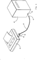
- Fig. 1 is perspective view showing a data processor and a printer connected to each other by a parallel printer interface of the present invention.
- Fig. 2 is a schematic diagram of the parallel printer interface of the present invention showing connections between pins of a connector of the data processor and pins of a connector of the printer.
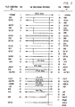
- Fig. 3 is a table showing levels of various signals at the data processor or printer producing interface states for the interface control protocols.
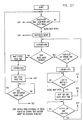
- Fig. 4 is a diagram of the interface states and the conditions under which there may be transition from one state to another.
- Fig. 5 is a flow chart showing initialization of the printer.
- Figs. 6-8 are flow charts showing a main loop of the printer.
- Fig. 9 is a flow chart showing a receiving status channel operation of the data processor or the printer.
- Fig. 10 is a flow chart showing a receiving data channel operation of the data processor or the printer.
- Fig. 11 is a flow chart showing a transmit status channel operation of the data processor or the printer.
- Fig. 12 is a flow chart showing a transmit data channel operation of the data processor.
- Fig. 13-15 are flow charts showing initialization of the data processor.
- Fig. 16-18 are flow charts showing a main loop of the data processor.
- Fig. 19 is a timing diagram showing the relationship between signals driven by the printer and signals driven by the data processor when the data processor initializes the printer through the interface of the present invention.
- Fig. 20 is a table showing the duration of each timing signal of Fig. 19.
- Fig. 21 is a timing diagram showing the relationship between signals driven by the data processor and signals driven by the printer when the data processor is seeking use of the interface of the present invention to transmit status signals to the printer.
- Fig. 22 is a table showing the duration of each timing signal of Fig. 21.
- Fig. 23 is a timing diagram showing the relationship between signals driven by the data processor and signals driven by the printer when the printer is seeking to use the interface of the present invention to send status signals to the data processor.
- Fig. 24 is a table showing the duration of each timing signal of Fig. 23.
- Fig. 25 is a timing diagram showing the relationship between signals from the data processor and signals from the printer when there is a byte by byte transfer from the data processor to the printer or vice versa.
- Fig. 26 is a table showing the duration of each timing signal of Fig. 25.
- Fig. 27 is a flow chart showing a sending protocol in the data processor for transmitting bytes.
- Fig. 28 is a flow chart showing a receiving protocol in the data processor for receiving bytes.
- Fig. 29 is a block diagram of a driver and receiver circuit in the data processor for producing or receiving information signals over one of the eight information lines between the data processor and the printer.
- Fig. 30 is a block diagram of a driver circuit in the data processor for producing a -STROBE or -AUTOFD signal as its output.
- Fig. 31 is a block diagram of a driver circuit in the data processor for producing an -INIT or -SLCTIN signal as its output.
- Fig. 32 is a block diagram of a receiver circuit in the data processor for receiving a -ERROR, +SLCT, or +PE signal from the printer.
- Fig. 33 is a block diagram of a receiver circuit in the data processor for receiving a -ACK or +BUSY signal from the printer.
- Fig. 34 is a block diagram of a driver and receiver circuit in the printer for producing or receiving information signals over one of the eight information lines between the data processor and the printer.
- Fig. 35 is a block diagram of a driver circuit in the printer for producing a +BUSY signal as its output.
- Fig. 36 is a block diagram of a driver circuit in the printer for producing a -ACK signal as its output.
- Fig. 37 is a block diagram of a driver circuit in the printer for producing a -ERROR, +SLCT, or +PE signal as its output.
- Fig. 38 is a block diagram of a receiver circuit in the printer for receiving a -INIT or -SLCTIN signal from the data processor.
- Fig. 39 is a block diagram of a receiver circuit in the printer for receiving a -STROBE or -AUTOFD from the data processor.
- Fig. 40 is a diagram of transmit hardware states for the printer.
- Fig. 41 is a diagram of receive hardware states for the printer.
- a PS/2 computer 40 which is a data processor, connected to a printer 41 by a cable 42.
- a cable 42 is sold by International Business Machines Corporation as Part No. 68X3949.
- the cable 42 has a cable terminal connector 43 on one end connected to a twenty-five pin female D connector 44 of the PS/2 computer 40 and a cable terminal connector 45 at its other end connected to a thirty-six pin Centronics compatible connector 46 of the printer 41.
- the connections of the various pins of the connectors 44 and 46 are shown in Fig. 2 with the signal between the connected pins being shown at each pin.
- the direction of each signal is indicated by an arrow if unidirectional and by arrows on opposite ends if bi-directional.
- Some of the signals also are identified by a different name under the "Bi-Directional Protocol" heading.
- the interface signals between the PS/2 computer 40 and the printer 41 are:
- DATA1-8 Information signals for transmitting data or status signals from the PS/2 computer 40 to the printer 41 and status signals from the printer 41 to the PS/2 computer 40.
- This signal acknowledges that the information has been received by the printer 41 through producing a negative going pulse to verify the completed transfer of each byte.
- this signal clocks the information into the PS/2 computer 40.
- Totem pole drivers are used to improve the rise time of this-signal.
- This signal provides a DC level (high) to indicate that the printer 41 cannot receive information, either data or status signals. This signal also is active when the printer 41 is off line or reporting an error. When this signal is low, the printer 41 can receive information. Totem pole drivers are used to improve the rise time of this signal.
- This signal from the printer 41 is interpreted as Printer Request to Send (-Prt 25 RTS) when the PS/2 computer 40 is arbitrating for control of the parallel interface.
- This signal is normally held high by the printer 41 so as not to be requesting to send and goes low only when the printer 41 wants to
- This signal is interpreted as -PS/2 Status Qualifier (-PS/2 StQ) when transmitted from the PS/2 computer 40 in the bi-directional mode.
- -PS/2 StQ -PS/2 Status Qualifier
- This signal goes low, it causes +BUSY to go high until the printer 41 is prepared to receive status signals from the PS/2 computer 40 at which time the printer 41 will set +BUSY low.
- This signal must be left low for the duration of transmission of the status signals. Since this signal is used by the PS/2 computer 40 to initialize the printer 41 and the PS/2 computer 40 may initialize the printer 41 at any time with the printer 41 in any mode, the PS/2 computer 40 must not allow -STROBE to fall during a 25 printer initialization sequence.
- This signal from the printer 41 is,the mirror image of -INIT. This signal is interpreted as -Printer Status Qualifier (-Prt StQ) when the printer 41 is in the bidirectional mode.
- This signal is interpreted as -Service Request (-Serv Req) when the printer 41 is in the bi-directional mode.
- -Serv Req -Service Request
- the PS/2 computer 40 To activate the bi-directional mode so that the printer 41 can transmit information as well as receive it, the PS/2 computer 40 must perform the following sequence of operations:
- the printer 41 is initialized by the PS/2 computer 40 setting the -INIT signal low for at least fifty microseconds to assure that the PS/2 computer 40 and the printer 41 will remain in sync if the printer 41 is bi-directional but is unable to respond due to an electrical fault in the interface.
- the PS/2 computer 40 knows that the printer 41 is in the bi-directional mode and will only return to Receive Only if commanded by the PS/2 computer 40, initialized, or powered off.
- interface ownership by the PS/2 computer 40 or the printer 41 and the Data Status Channel transmissions are managed by the use of a state model of the Interface Control protocols (see Fig. 3) in which the allowed states are defined. These states are indicated by examining the levels of Status Qualifier (StQ), Busy, and Request to Send (RTS) signals from the PS/2 computer 40 or the printer 41.
- StQ Status Qualifier
- RTS Request to Send
- the PS/2 computer 40 or the printer 41 is completely prepared to receive Data or Status bytes.
- the PS/2 computer 40 has allocated a buffer for the incoming bytes, is aware if the bytes are Data or Status, and has completely programmed the Direct Memory Access (DMA) or Bus Master (interface) hardware to accept bytes if these facilities are to be used.
- DMA Direct Memory Access
- Bus Master interface
- PS/2 computer 40 or the printer 41 may return to NOT READY TO RECEIVE when its counterpart leaves the TRANSMIT DATA or TRANSMIT STATUS state.
- This state is the idle state of a unidirectional printer.
- the printer 41 or the PS/2 computer 40 enters this state when it is processing a previously received byte, is off line, is processing a change of the StQ or RTS input signal, is changing to another state, or is idle. When the transmitter sees its receiver in this state, it should not transfer bytes. If the PS/2 computer 40 or the printer 41 enters this state from the READY TO RECEIVE state asynchronously, is must be capable of taking up to one byte because of a race with the other of the PS/2 computer 40 and the printer 41. This is the normal idle state of the PS/2 computer 40 or the bi-directioanl printer 41.
- the PS/2 computer 40 After waiting a one microsecond minimum "de-race" delay without encountering its RTS input signal going true as long as its StQ signal remains false, the PS/2 computer 40 will transition to the TRANSMIT DATA state as soon as the printer 41 goes READY TO RECEIVE.
- the PS/2 computer 40 When the PS/2 computer 40 is in this state, it has control of the interface and is actively transmitting on the logical Data channel. DMA or Bus Master transmission should not be initiated until this state is reached. The PS/2 computer 40 will exit this state upon completing the transmission requested or if its StQ or RTS input signal goes true. The PS2/ computer 40 must recognize the printer 41 is in the READY TO RECEIVE state and send a byte at least every ten milliseconds. If the PS/2 computer 40 cannot transmit a byte within the required ten milliseconds, it should drop control of the interface until the data is available.
- PS/2 computer 40 If the PS/2 computer 40 is in this state, it is attemping to gain control of the interface to transmit Status signals. It will transition to the TRANSMIT STATUS state after waiting a one microsecond minimum "de-race" delay without encountering the StQ input signal going true when the printer 41 is in the READY TO RECEIVE state.
- the printer 41 If the printer 41 is in this state, it is attempting to gain control of the interface to send a response to a previous request from the PS/2 computer 40.
- the printer 41 will enter the TRANSMIT STATUS state after waiting the one microsecond minimum "de-race" delay without encountering the StQ input going true when the PS/2 computer 40 enters the READY TO RECEIVE state.
- This state is used to actively send Status information. DMA or Bus Master transmission should not be initiated until this state is reached.
- the PS/2 computer 40 or the printer 41 will exit this state upon completing the transmission requested or if its StQ input signal goes true.
- the PS/2 computer 40 or the printer 41 must recognize its counterpart is in its READY TO RECEIVE state and send a byte at lease every ten milliseconds. If it cannot transmit a byte within the required ten milliseconds, it should drop control of the interface until the data is available.
- the flow chart of Fig. 4 discloses a schematic representation of the defined states, the allowed transitions, and the requirements to make a transition.
- the name of the state in the box describes the condition of the outputs of the PS/2 computer 40 or the printer 41, and the notations on the path lines describe the required state of the inputs that must be present to take that specific path.
- printer 41 While the printer 41 is not shown and described as transmitting data to the PS/2 computer 40 so that it does not. enter the REQUEST INTERFACE FOR DATA or TRANSMIT DATA state, is should be understood that the printer 41 could transmit data to the PS/2 computer 40. Thus, only -ERROR would have to change its level for this to occur, and the REQUEST INTERFACE FOR DATA and TRANSMIT DATA states would be applicable to the printer 41.
- FIG. 5 shows initialization of the printer 41
- Figs. 6-8 disclosing the main loop of the printer 41
- Fig. 9 showing the receive status channel
- Fig. 10 disclosing the receive data channel
- Fig. 11 showing the transmit status channel
- Fig. 12 disclosing the transmit data channel
- Figs. 13-15 disclosing initialization of the PS/2 computer 40
- Figs. 16-18 showing the main loop of the PS/2 computer 40.
- Initialization of the printer 41 by the PS/2 computer 40 may occur at any time. Initialization of the printer 41 occurs during power on reset or when certain conditions occur in the flow charts of Figs. 6-8.
- Fig. 19 shows the timing relationship of the signals driven by the PS/2 computer 40 and the printer 41 during initialization of the printer 41.
- Fig. 20 discloses the time for each of T1 to T6 in Fig. 19.
- the printer 41 will print all buffered data before dropping +BUSY after -INIT rises to cause initialization of the printer 41.
- the printer 41 assumes the falling edge of a -INIT signal is a CHANNEL BREAK signal by the PS/2 computer 40 with -SLCTIN low and +BUSY may be dropped to allow receipt of Status information.
- the printer 41 sets +BUSY high as a result of the falling or rising edge of -INIT through hardware, but the microcode of the printer 41 sets +BUSY low shortly after it goes high and then +BUSY paces incoming Status information.
- Fig. 21 shows the timing relationship of the signals driven by the PS/2 computer 40 and the printer 41.
- Fig. 22 discloses the time for each of T1 to T4 of Fig. 21.
- Fig. 23 discloses the timing relationship of the signals driven by the PS/2 computer 40 and the printer 41, and the time for each of T1 to T3 of Fig. 23 is in Fig. 24.
- Fig. 25 discloses the timing relation for transmitting each byte from the PS/2 computer 40 to the printer 41, and the time for each of T1 to T10 of Fig. 25 is in Fig. 26.
- -STROBE and -ACK should be swapped in Fig. 25, and +BUSY of Fig. 25 replaced with -AUTOFD.
- the "Closed Loop Handshake” requires the PS/2 computer 40 to have the sending protocol of Fig. 27 when transmitting from the PS/2 computer 40 to the printer 41; the sending protocol is quart of an integrated circuit in the PS/2 computer 40. In the flow chart of Fig. 27, the value for each of Data Setup, Strobe Hold, and Data Hold times is the same as that required for automatic STROBE generation.
- the "Closed Loop Handshake” requires the PS/2 computer 40 to have the receiving protocol of Fig. 28 when the PS/2 computer 40 is receiving bytes from the printer 41; the receiving protocol is part of the same integrated circuit as the sending protocol of Fig. 27.
- the drivers are a tri-state (TS) driver, an open collector (OC) driver, and a totem pole (TP) driver.
- the receiver is an LSTTL (LS) receiver.
- TS tri-state
- OC open collector
- TP totem pole
- LS LSTTL
- the tri-state driver must be able to be tri-stated and present a minimum impedance of 20k ohms to +5 volts or ground when tri-stated.
- the tri-state driver When the tri-state driver is enabled, it must be able to sink at least 24 milliamps with a maximum down level of 0.5 volt and must be able to source at least 15 milliamps with a minimum up level of 2 volts.
- the tri-state driver must be able to sustain a voltage on its output as much as 5.5 volts above its VCC when powered off. Suitable examples of the tri-state driver are 74LS244, 74LS245, 74F125, and 74F126.
- the open collector driver must or able to sink at least 16 milliamps with a maximum down level of 0.5 volt. When the open collector driver is off, it must present a minimum impedance of 100K ohms to ground. The open collector driver must be able to sustain a voltage on its output as much as 5.5 volts above its VCC when powered off. Suitable examples of the open collector driver are 7406 and 7407.
- the totem pole driver must be able to sink at least 24 milliamps with a maximum down level of 0.5 volt and must be able to source at least 15 milliamps with a minimum up level of 2 volts.
- the totem pole driver also must be able to sustain a voltage on its output as much as 5.5 volts above its VCC when powered off. Suitable examples of the totem pole driver are 74LS244, 74LS245, 74F125, and 74F126.
- the LSTTL receiver must have a minimum high level input voltage of 2 volts and a maximum low level input voltage of 0.8 volt.
- the LSTTL receiver requires a maximum of 1.6 milliamps of sink current and 40 microamps of source current from its driver.
- the LSTTL receiver must be able to sustain a voltage on its input as much as 5.5 volts above its VCC when powered off. Suitable examples of the LSTTL receiver are 74LS04, 74LS244, and 74LS245.
- the PS/2 computer 40 has driver and receiver circuits for receiving and transmitting data and status information.
- One of the circuits which are equal in number to eight information lines between the PS/2 computer 40 and the printer 41, is shown in Fig. 29.
- Each of the -STROBE and -AUTOFD signals is produced by a driver circuit (see Fig. 30) in the PS/2 computer 40.
- a driver circuit see Fig. 30
- Each of the -INIT and -SLCTIN signals is produced by a driver circuit (see Fig. 31) in the PS/2 computer 40. Accordingly, there are two of the driver circuits of Fig. 31 in the PS/2 computer 40.
- the PS/2 computer 40 has three separate receiver circuits (see Fig. 32) for receiving -ERROR, +SLCT, and +PE signals from the printer 41.
- the PS/2 computer 40 has two separate receiver circuits (see Fig. 33) for receiving -ACK and +BUSY signals from the printer 41.
- the printer 41 has driver and receiver circuits for receiving and transmitting information.
- the printer 41 has a driver circuit (see Fig. 35) for producing the +BUSY signal.
- the printer 41 has a driver circuit (see Fig. 36) for producing the -ACK signal.
- Each of the -ERROR, +SLCT, and +PE signals is produced by a separate driver circuit (see Fig. 37) in the printer 41.
- the printer has three of the driver circuits of Fig. 37.
- Each of the -INIT and -SLCTIN signals from the PS/2 computer 40 is received at the printer 41 through a separate receiver circuit (see Fig. 38).
- Each of the -STROBE and -AUTOFD signals from the PS/2 computer 40 is received at the printer 41 through a separate receiver circuit (see Fig. 39).
- the closed loop transmit process which is performed on a byte to byte basis by the hardware of the printer 41, is shown in a hardware state diagram in Fig. 40. It is assumed that the Direct Memory Access (DMA) ability is in the printer 41 with independent transmit and receive DMA channels.
- DMA Direct Memory Access
- TxDMAArm Set or Reset by microcode of the printer 41 to enable or disenable DMA transmit. This bit should be set low before modifying any Transmit DMA controls since this bit is sampled by the Synchronous Control Machine to make branching decisions.
- TxDMAPar/Ser Set or Reset by the microcode of the printer 41 to set the port for transmit with a logical one for parallel transmission and a logical zero for serial transmission.
- TxCount 0 This indicates that the Transmit DMA's transfer account has been exhausted.
- ParOBFull Parallel Output Buffer Full
- ParDMATx TxDMAArm * TxDMAPar/Ser * TxCount 0 ParTxDone Set when authorized parallel transmit is done. This causes interrupt of a program in the printer 41 so that another program in the printer 41 can execute. Reset by the microcode of the printer 41. Time400 Goes active 400 nanoseconds after started to insure the 400 nanosecond set up time is met. Short AckPulse Drives -ACK low for 500 nanoseconds
- the receive process which is performed on a byte to byte basis by the printer 41, is shown in a hardware state diagram ( see Fig. 41 ).
- ParDMARx RxDMAArm * RxDMAPar/Ser * RxCount 0 * INITMisMatch * MatchQ ParDMATx Same as for Fig. 40
- DMABusy Used to hold the +BUSY signal to the PS/2 computer 40 at the end of DMA transfers.
- AbortRx Set if Synchronous Control Machine is waiting for -STROBE(idle) and RxDMAArm is reset. This causes interrupt of a program in the printer 41 so that another program in the printer 41 can execute.
- the PS/2 computer 40 and the printer 41 interact to provide a function or recover from a situation.
- An example of the PS/2 computer 40 and the printer 41 interacting when the printer 41 informs the PS/2 computer 40 of completion of a job is as follows:
- Another example of interaction between the PS/2 computer 40 and the printer 41 is when the PS/2 computer 40 requests the printer 41 to use a font that is not in the memory of the printer 41.
- a third example of interaction between the PS/2 computer 40 and the printer 41 is when there is a remote operator panel query for paper size.
- the operations are as follows:
- An advantage of this invention is that an interface can be used with a unidirectional or bi-directional printer. Another advantage of this invention is that it reduces the amount of memory for a printer to save when it receives a system control signal in comparison with when it receives a printer content signal. A further advantage of this invention is that channel bandwidth is increased so that the printing job is completed faster. Still another advantage of this invention is that the same information lines can be utilized to transmit data or status information between a data processor and a printer. A still further advantage of this invention is that there is requirement for latching any data in a data processor. Yet another advantage of this invention is that there is no removal of information from the information lines until the information has been accepted by the receiver.
- a yet further advantage of this invention is that sprinter status can be ascertained by a user without the user being physically present at the printer. Yet still another advantage of this invention is that an inquiry can be sent to a printer from a data processor without interrupting the information streame to the printer. A yet still further advantage of this invention is that a printer can interrupt incoming information.
Landscapes
- Engineering & Computer Science (AREA)
- Theoretical Computer Science (AREA)
- Physics & Mathematics (AREA)
- General Engineering & Computer Science (AREA)
- General Physics & Mathematics (AREA)
- Human Computer Interaction (AREA)
- Accessory Devices And Overall Control Thereof (AREA)
Abstract
Description
- This invention relates to a bi-directional parallel interface between two devices and, more particularly, to a bidirectional parallel printer interface between a data processor and a printer in which either may transmit signals to the other or receive signals from the other.
- A parallel printer interface has previously been used between an IBM PC and a printer. Information was transmitted only from the IBM PC to the printer since the printer was a unidirectional printer, that is, a printer capable of only receiving information. As a result, the unidirectional printer required a printer operator panel at the printer to enable an operator to ascertain why the printer could no longer receive data from the IBM PC, for example. Thus, this prior printer interface could not be efficiently utilized if the printer was remote from the operator such as when driving the printer via a Local Area Network (LAN) or when the printer was shared by a plurality of users.
- The IBM PS/2 personal computer has a bi-directional parallel interface for using a software program, which is known as Data Migration Facility, in which data can be transferred from a 5 1/4˝ disk of the IBM PC to a 3 1/2˝ disk of the PS/2 personal computer to enable transfer of data from an IBM PC to a PS/2 personal computer. However, the PS/2 personal computer has not been capable of receiving information from a printer nor has there been a printer capable of supplying information to the PS/2 computer if the PS/2 computer were capable of receiving the information. Therefore, even with the PS/2 computer, is has been necessary for the operator to be near the printer to allow the operator to view the printer operator panel to determine the problem whenever information could not be sent to the printer.
- While the PS/2 computer has not been capable of receiving information from a printer, U.S. patent 4,651,278 to Herzog et al has communication from a host system to an all points addressable printer and vice versa by a printer interface to that the printer is bi-directional. However, there does not appear to be communication from the printer to the host system after printing begins. Therefore, information is not sent from the printer to the host system to inform a remote user of why information cannot be sent to the printer, for example.
- The interface of the aforesaid Herzog et al patent is an independent interface using a specific language. The interface of the aforesaid Herzog et al patent also transmits the information in structured field data streams, which are blocks, and not bytes. Thus, there can be no interruption of each block in the aforesaid Herzog et al patent to permit the printer to communicate with the host system.
- The interface of the present invention satisfactorily solves the problem of the printer being remote from the operator and the operator still being able to ascertain the status of the printer at any time without the operator having to physically go to the printer. The interface of the present invention transmits information byte by byte so that there can be an interruption at any byte boundary of the transmitted information by the receiver of the information or by the transmitter. This enables the data processor to stop sending information and to inquire of the printer why the printer is no longer accepting the information, for example.
- The interface of the present invention also enables the printer to send information at any time after the data processor recognizes the printer's request to send information and the data processor stops sending information. This allows the printer to inform the data processor that a font, for example, required by the information transmitted to the printer from the data processor is not available in the printer.
- The interface of the present invention accomplishes this through providing a first dedicated line between the data processor and the printer in which the data processor can inform the printer as to whether the information to be transmitted is data or status signals. The data signals would be print content signals for the printer to use for printing. The status signals, for example would inquire as to why the printer was not accepting information. By informing the printer that status signals, which are system control signals, are to be transmitted, the printer does not have to save as much memory as is necessary when data signals, which are print content signals, are being sent to the printer.
- The interface of the present invention also provides a second dedicated line between the data processor and the printer in which the printer can inform the data processor that the printer is going to send information to the data processor. This can be in response to the data processor's question so that the printer can explain to the data processor why the printer is not accepting information from the data processor. All information transmitted between the data processor and the printer is sent over the same eight information lines, which are separate from the dedicated lines.
- The interface of the present invention also is capable of permitting the printer to communicate to the data processor that it wants to interrupt the incoming stream of data signals from the data processor to tell the data processor something. For example, the printer may want to inform the data processor that it does not have a specific font that has been called out in the data signals being sent to the printer by the data processor.
- The interface of the present invention also is capable of utilization with unidirectional printers. An initial command signal from the data processor is not accepted by an unidirectional printer so that the unidirectional printer ignores signals usable only with a bi-directional printer, that is, a printer capable of transmitting or receiving information.
- An advantage of this invention is to provide a parallel interface to enable communications of a data processor with both unidirectional and bi-directional printers.
- Another advantage of this invention is to provide a parallel interface that enables a data processor to know whether it is communicating with a unidirectional or bi-directional printer.
- A further advantage of this invention is to provide a dynamic parallel interface that enables communication between a data processor and a bi-directional printer in either directions at any time.
- Still another advantage of this invention is to provide a parallel interface having a relatively high transfer rate of information.
- Fig. 1 is perspective view showing a data processor and a printer connected to each other by a parallel printer interface of the present invention.
- Fig. 2 is a schematic diagram of the parallel printer interface of the present invention showing connections between pins of a connector of the data processor and pins of a connector of the printer.
- Fig. 3 is a table showing levels of various signals at the data processor or printer producing interface states for the interface control protocols.
- Fig. 4 is a diagram of the interface states and the conditions under which there may be transition from one state to another.
- Fig. 5 is a flow chart showing initialization of the printer.
- Figs. 6-8 are flow charts showing a main loop of the printer.
- Fig. 9 is a flow chart showing a receiving status channel operation of the data processor or the printer.
- Fig. 10 is a flow chart showing a receiving data channel operation of the data processor or the printer.
- Fig. 11 is a flow chart showing a transmit status channel operation of the data processor or the printer.
- Fig. 12 is a flow chart showing a transmit data channel operation of the data processor.
- Fig. 13-15 are flow charts showing initialization of the data processor.
- Fig. 16-18 are flow charts showing a main loop of the data processor.
- Fig. 19 is a timing diagram showing the relationship between signals driven by the printer and signals driven by the data processor when the data processor initializes the printer through the interface of the present invention.
- Fig. 20 is a table showing the duration of each timing signal of Fig. 19.
- Fig. 21 is a timing diagram showing the relationship between signals driven by the data processor and signals driven by the printer when the data processor is seeking use of the interface of the present invention to transmit status signals to the printer.
- Fig. 22 is a table showing the duration of each timing signal of Fig. 21.
- Fig. 23 is a timing diagram showing the relationship between signals driven by the data processor and signals driven by the printer when the printer is seeking to use the interface of the present invention to send status signals to the data processor.
- Fig. 24 is a table showing the duration of each timing signal of Fig. 23.
- Fig. 25 is a timing diagram showing the relationship between signals from the data processor and signals from the printer when there is a byte by byte transfer from the data processor to the printer or vice versa.
- Fig. 26 is a table showing the duration of each timing signal of Fig. 25.
- Fig. 27 is a flow chart showing a sending protocol in the data processor for transmitting bytes.
- Fig. 28 is a flow chart showing a receiving protocol in the data processor for receiving bytes.
- Fig. 29 is a block diagram of a driver and receiver circuit in the data processor for producing or receiving information signals over one of the eight information lines between the data processor and the printer.
- Fig. 30 is a block diagram of a driver circuit in the data processor for producing a -STROBE or -AUTOFD signal as its output.
- Fig. 31 is a block diagram of a driver circuit in the data processor for producing an -INIT or -SLCTIN signal as its output.
- Fig. 32 is a block diagram of a receiver circuit in the data processor for receiving a -ERROR, +SLCT, or +PE signal from the printer.
- Fig. 33 is a block diagram of a receiver circuit in the data processor for receiving a -ACK or +BUSY signal from the printer.
- Fig. 34 is a block diagram of a driver and receiver circuit in the printer for producing or receiving information signals over one of the eight information lines between the data processor and the printer.
- Fig. 35 is a block diagram of a driver circuit in the printer for producing a +BUSY signal as its output.
- Fig. 36 is a block diagram of a driver circuit in the printer for producing a -ACK signal as its output.
- Fig. 37 is a block diagram of a driver circuit in the printer for producing a -ERROR, +SLCT, or +PE signal as its output.
- Fig. 38 is a block diagram of a receiver circuit in the printer for receiving a -INIT or -SLCTIN signal from the data processor.
- Fig. 39 is a block diagram of a receiver circuit in the printer for receiving a -STROBE or -AUTOFD from the data processor.
- Fig. 40 is a diagram of transmit hardware states for the printer.
- Fig. 41 is a diagram of receive hardware states for the printer.
- Referring to the drawings and particularly Fig. 1, there is shown a PS/2
computer 40, which is a data processor, connected to aprinter 41 by acable 42. One suitable example of thecable 42 is sold by International Business Machines Corporation as Part No. 68X3949. - The
cable 42 has acable terminal connector 43 on one end connected to a twenty-five pinfemale D connector 44 of the PS/2computer 40 and acable terminal connector 45 at its other end connected to a thirty-six pin Centronicscompatible connector 46 of theprinter 41. The connections of the various pins of theconnectors - The interface signals between the PS/2
computer 40 and theprinter 41 are: - DATA1-8 Information signals for transmitting data or status signals from the PS/2
computer 40 to theprinter 41 and status signals from theprinter 41 to the PS/2computer 40. - -STROBE Clocks information into the printer 41 a byte at a time. When the PS/2
computer 40 is receiving information from theprinter 41, this signal verifies the completed transfer of each byte to the PS/2computer 40 from theprinter 41. Totem pole drivers are used to improve the rise time of this signal. - -ACK This signal acknowledges that the information has been received by the
printer 41 through producing a negative going pulse to verify the completed transfer of each byte. When the PS/2computer 40 is receiving information from theprinter 41, this signal clocks the information into the PS/2computer 40. Totem pole drivers are used to improve the rise time of this-signal. - +BUSY This signal provides a DC level (high) to indicate that the
printer 41 cannot receive information, either data or status signals. This signal also is active when theprinter 41 is off line or reporting an error. When this signal is low, theprinter 41 can receive information. Totem pole drivers are used to improve the rise time of this signal. - -AUTOFD This is the mirror image of +BUSY and is from the PS/2
computer 40 so that it is interpreted as +PS/2 Busy. - +SLCT This signal from the
printer 41 is interpreted as Printer Request to Send (-Prt 25 RTS) when the PS/2computer 40 is arbitrating for control of the parallel interface. This signal is normally held high by theprinter 41 so as not to be requesting to send and goes low only when theprinter 41 wants to - -SLCTIN This signal from the PS/2
computer 40 is interpreted as -PS/2 Request to Send (-PS/2 RTS) and is transmitted to lock control of the parallel interface for transmitting signal must be set low (-PS/2 RTS = True) to cause theprinter 41 to drop its +BUSY signal and receive information, either data or status signals, from the PS/2computer 40. - -INIT This signal is interpreted as -PS/2 Status Qualifier (-PS/2 StQ) when transmitted from the PS/2
computer 40 in the bi-directional mode. When this signal goes low, it causes +BUSY to go high until theprinter 41 is prepared to receive status signals from the PS/2computer 40 at which time theprinter 41 will set +BUSY low. This signal must be left low for the duration of transmission of the status signals. Since this signal is used by the PS/2computer 40 to initialize theprinter 41 and the PS/2computer 40 may initialize theprinter 41 at any time with theprinter 41 in any mode, the PS/2computer 40 must not allow -STROBE to fall during a 25 printer initialization sequence. - -ERROR This signal from the
printer 41 is,the mirror image of -INIT. This signal is interpreted as -Printer Status Qualifier (-Prt StQ) when theprinter 41 is in the bidirectional mode. - +PE This signal is interpreted as -Service Request (-Serv Req) when the
printer 41 is in the bi-directional mode. When theprinter 41 detects a condition that the PS/2computer 40 has armed it to detect, this signal will be set low until the PS/2computer 40 has been informed of the detection. - While the connections between the connectors 44 (see Fig. 1) and 46 have been shown in Fig. 2 for use with the lines of the cable 42 (see Fig. 1), it should be understood that a new cable could be utilized instead of the
cable 42 in which the pin 25 (see Fig. 2) of the connector 44 (see Fig. 1) of the PS/2computer 40 can be connected to PARITY rather than to ground. The new cable also would connect thepin 25 of the connector 44 (see Fig. 1) to pin 16 of the connector 46 (see Fig. 1) of theprinter 41 rather than pin 30 (see Fig. 2). This arrangement would be utilized when parity is to be generated and checked. - When the PS/2 computer 40 (see Fig. 1) and the
printer 41 are powered on, each assumes that it is operating in a mode in which theprinter 41 is unidirectional rather than bi-directional. The basic assumptions are that data transfer is unidirectional from the PS/2computer 40 to theprinter 41, theprinter 41 can accept data as long as +BUSY is not active, theprinter 41 will correctly capture data from the PS/2computer 40 if the correct set up, STROBE width, and hold time requirements are met, theprinter 41 will verify receipt of a byte by pulsing -ACK, and theprinter 41 may be initialized at any time, whether +BUSY is high or low, by the PS/2computer 40 sending a -INIT signal active (low) for at least fifty microseconds, and theprinter 41 will proceed to print all queued data before setting +BUSY low. - To activate the bi-directional mode so that the
printer 41 can transmit information as well as receive it, the PS/2computer 40 must perform the following sequence of operations: -
- a) The PS/2
computer 40 sets -INIT low and theprinter 41 will respond by setting +BUSY high (+BUSY need not be low to start); - (b) When the
printer 41 is prepared to receive the Status Command, it will set +BUSY low to allow the Status Command to be sent. If theprinter 41 does not set +BUSY low within 500 microseconds, the PS/2computer 40 can assume that theprinter 41 is uni-directional or bi-directional but cannot respond due to hardware fault. -
- a) The
printer 41 will respond to the Status Command within 0.5 second when it is bi-directional; - (b) If no response is received within 0.5 second, the PS/2
computer 40 should assume that theprinter 41 is only capable of unidirectional operation. - When operating in the bi-directional mode, interface ownership by the PS/2
computer 40 or theprinter 41 and the Data Status Channel transmissions are managed by the use of a state model of the Interface Control protocols (see Fig. 3) in which the allowed states are defined. These states are indicated by examining the levels of Status Qualifier (StQ), Busy, and Request to Send (RTS) signals from the PS/2computer 40 or theprinter 41. - The interface states of Fig. 3 are as follows:
- When in this state, the PS/2
computer 40 or theprinter 41 is completely prepared to receive Data or Status bytes. For example, the PS/2computer 40 has allocated a buffer for the incoming bytes, is aware if the bytes are Data or Status, and has completely programmed the Direct Memory Access (DMA) or Bus Master (interface) hardware to accept bytes if these facilities are to be used. When a transmitter sees this state in a receiver, it may begin transfer of information immediately. - If the PS/2
computer 40 or theprinter 41 is in this state and receiving Data or Status Channel bytes, it may return to NOT READY TO RECEIVE when its counterpart leaves the TRANSMIT DATA or TRANSMIT STATUS state. - This state is the idle state of a unidirectional printer.
- The
printer 41 or the PS/2computer 40 enters this state when it is processing a previously received byte, is off line, is processing a change of the StQ or RTS input signal, is changing to another state, or is idle. When the transmitter sees its receiver in this state, it should not transfer bytes. If the PS/2computer 40 or theprinter 41 enters this state from the READY TO RECEIVE state asynchronously, is must be capable of taking up to one byte because of a race with the other of the PS/2computer 40 and theprinter 41. This is the normal idle state of the PS/2computer 40 or thebi-directioanl printer 41. - When the PS/2
computer 40 is in this state, it is attemping to gain control of the interface to transmit data. - After waiting a one microsecond minimum "de-race" delay without encountering its RTS input signal going true as long as its StQ signal remains false, the PS/2
computer 40 will transition to the TRANSMIT DATA state as soon as theprinter 41 goes READY TO RECEIVE. - When the PS/2
computer 40 is in this state, it has control of the interface and is actively transmitting on the logical Data channel. DMA or Bus Master transmission should not be initiated until this state is reached. The PS/2computer 40 will exit this state upon completing the transmission requested or if its StQ or RTS input signal goes true. The PS2/computer 40 must recognize theprinter 41 is in the READY TO RECEIVE state and send a byte at least every ten milliseconds. If the PS/2computer 40 cannot transmit a byte within the required ten milliseconds, it should drop control of the interface until the data is available. - If the PS/2
computer 40 is in this state, it is attemping to gain control of the interface to transmit Status signals. It will transition to the TRANSMIT STATUS state after waiting a one microsecond minimum "de-race" delay without encountering the StQ input signal going true when theprinter 41 is in the READY TO RECEIVE state. - If the
printer 41 is in this state, it is attempting to gain control of the interface to send a response to a previous request from the PS/2computer 40. Theprinter 41 will enter the TRANSMIT STATUS state after waiting the one microsecond minimum "de-race" delay without encountering the StQ input going true when the PS/2computer 40 enters the READY TO RECEIVE state. -
- This state is used to actively send Status information. DMA or Bus Master transmission should not be initiated until this state is reached. The PS/2
computer 40 or theprinter 41 will exit this state upon completing the transmission requested or if its StQ input signal goes true. - The PS/2
computer 40 or theprinter 41 must recognize its counterpart is in its READY TO RECEIVE state and send a byte at lease every ten milliseconds. If it cannot transmit a byte within the required ten milliseconds, it should drop control of the interface until the data is available. - The flow chart of Fig. 4 discloses a schematic representation of the defined states, the allowed transitions, and the requirements to make a transition. In Fig. 4, the name of the state in the box describes the condition of the outputs of the PS/2
computer 40 or theprinter 41, and the notations on the path lines describe the required state of the inputs that must be present to take that specific path. - The following explains the notes referenced on Fig. 4:
- 1. As the PS/2
computer 40 or theprinter 41 enters the READY TO RECEIVE state, the level of the StQ signal should be noted to determine if Data or Status information is being received. For the PS/2computer 40 receiving in the Programmed Input Output (PIO) mode, the state of -ERROR should be noted as every byte is received. - 2. The five millisecond minimum dwell time in the NOT READY TO RECEIVE state is only required when transmitting to the PS/2
computer 40 to assure that the PS/2computer 40 will not mix data and status transmission. Since the PS/2computer 40 in the PIO mode has no hardware to cause interrupt upon change of any of its -ERROR (StQ), +SLCT (RTS), or +BUSY (Busy) input, each byte must be noted and compared against expectation of Data or Status information as it is received by checking the level of the -ERROR signal. For the PS/2computer 40 using DMA Slave or Bus Master capabilities, interrupts may be generated upon change of its -ERROR (StQ), +SLCT (RTS), or +BUSY (Busy) input. The five millisecond dwell time allows the PS/2computer 40 to properly service these interrupts. - 3. While in the NOT READY TO RECEIVE state, the PS/2
computer 40 will prepare a "What" status command in response to theprinter 41 posting a Service Request (+PE = low). - 4. Unequal delays are used to prevent repeated collision for interface control.
- 5. The PS/2
computer 40 or theprinter 41 must recognize its counterpart is in READY TO RECEIVE and send a byte at least every ten milliseconds. If the PS/2computer 40 or theprinter 41 cannot transmit a byte within the required ten milliseconds, it should drop control of the interface until the information is available. - While the
printer 41 is not shown and described as transmitting data to the PS/2computer 40 so that it does not. enter the REQUEST INTERFACE FOR DATA or TRANSMIT DATA state, is should be understood that theprinter 41 could transmit data to the PS/2computer 40. Thus, only -ERROR would have to change its level for this to occur, and the REQUEST INTERFACE FOR DATA and TRANSMIT DATA states would be applicable to theprinter 41. - All of the Interface Control protocols are implemented in the PS/2
computer 40 and theprinter 41 in microcode so that they are designed to be tolerant for a wide variance in the times between steps of the protocol. The flow charts of Figs. 5-18 disclose the Interface Control protocols with Fig. 5 showing initialization of theprinter 41, Figs. 6-8 disclosing the main loop of theprinter 41, Fig. 9 showing the receive status channel, Fig. 10 disclosing the receive data channel, Fig. 11 showing the transmit status channel, Fig. 12 disclosing the transmit data channel, Figs. 13-15 disclosing initialization of the PS/2computer 40, and Figs. 16-18 showing the main loop of the PS/2computer 40. Whenever a flow chart has a block referring to another figure, this means to refer to that figure and perform the steps of the flow chart of that figure. - Initialization of the
printer 41 by the PS/2computer 40 may occur at any time. Initialization of theprinter 41 occurs during power on reset or when certain conditions occur in the flow charts of Figs. 6-8. Fig. 19 shows the timing relationship of the signals driven by the PS/2computer 40 and theprinter 41 during initialization of theprinter 41. Fig. 20 discloses the time for each of T1 to T6 in Fig. 19. - The
printer 41 will print all buffered data before dropping +BUSY after -INIT rises to cause initialization of theprinter 41. Theprinter 41 assumes the falling edge of a -INIT signal is a CHANNEL BREAK signal by the PS/2computer 40 with -SLCTIN low and +BUSY may be dropped to allow receipt of Status information. Theprinter 41 sets +BUSY high as a result of the falling or rising edge of -INIT through hardware, but the microcode of theprinter 41 sets +BUSY low shortly after it goes high and then +BUSY paces incoming Status information. - When the PS/2
computer 40 wants to request the interface for transmission of Status information to theprinter 41, theprinter 41 must be in its NOT READY TO RECEIVE state to enable this transaction to begin. Fig. 21 shows the timing relationship of the signals driven by the PS/2computer 40 and theprinter 41. Fig. 22 discloses the time for each of T1 to T4 of Fig. 21. - When the
printer 41 wants to request the interface to transmit Status information to the PS/2 computer 40 (This is called CHANNEL BREAK.), the PS/2computer 40 must be in its NOT READY TO RECEIVE status. Fig. 23 discloses the timing relationship of the signals driven by the PS/2computer 40 and theprinter 41, and the time for each of T1 to T3 of Fig. 23 is in Fig. 24. - Bytes of information are sent from the PS/2
computer 40 to theprinter 41 or vice versa through a "Closed Loop Handshake." Fig. 25 discloses the timing relation for transmitting each byte from the PS/2computer 40 to theprinter 41, and the time for each of T1 to T10 of Fig. 25 is in Fig. 26. When bytes of information are being transmitted from theprinter 41 to the PS/2computer 40, -STROBE and -ACK should be swapped in Fig. 25, and +BUSY of Fig. 25 replaced with -AUTOFD. - The "Closed Loop Handshake" requires the PS/2
computer 40 to have the sending protocol of Fig. 27 when transmitting from the PS/2computer 40 to theprinter 41; the sending protocol is quart of an integrated circuit in the PS/2computer 40. In the flow chart of Fig. 27, the value for each of Data Setup, Strobe Hold, and Data Hold times is the same as that required for automatic STROBE generation. The "Closed Loop Handshake" requires the PS/2computer 40 to have the receiving protocol of Fig. 28 when the PS/2computer 40 is receiving bytes from theprinter 41; the receiving protocol is part of the same integrated circuit as the sending protocol of Fig. 27. - To produce and receive the various signals, three different drivers and one receiver are utilized in the
printer 41 and two of the three drivers and the receiver are employed in the PS/2computer 40. The drivers are a tri-state (TS) driver, an open collector (OC) driver, and a totem pole (TP) driver. The receiver is an LSTTL (LS) receiver. Each of the devices has key electrical characteristics required by the interface. - The tri-state driver must be able to be tri-stated and present a minimum impedance of 20k ohms to +5 volts or ground when tri-stated. When the tri-state driver is enabled, it must be able to sink at least 24 milliamps with a maximum down level of 0.5 volt and must be able to source at least 15 milliamps with a minimum up level of 2 volts. The tri-state driver must be able to sustain a voltage on its output as much as 5.5 volts above its VCC when powered off. Suitable examples of the tri-state driver are 74LS244, 74LS245, 74F125, and 74F126.
- The open collector driver must or able to sink at least 16 milliamps with a maximum down level of 0.5 volt. When the open collector driver is off, it must present a minimum impedance of 100K ohms to ground. The open collector driver must be able to sustain a voltage on its output as much as 5.5 volts above its VCC when powered off. Suitable examples of the open collector driver are 7406 and 7407.
- The totem pole driver must be able to sink at least 24 milliamps with a maximum down level of 0.5 volt and must be able to source at least 15 milliamps with a minimum up level of 2 volts. The totem pole driver also must be able to sustain a voltage on its output as much as 5.5 volts above its VCC when powered off. Suitable examples of the totem pole driver are 74LS244, 74LS245, 74F125, and 74F126.
- The LSTTL receiver must have a minimum high level input voltage of 2 volts and a maximum low level input voltage of 0.8 volt. The LSTTL receiver requires a maximum of 1.6 milliamps of sink current and 40 microamps of source current from its driver. The LSTTL receiver must be able to sustain a voltage on its input as much as 5.5 volts above its VCC when powered off. Suitable examples of the LSTTL receiver are 74LS04, 74LS244, and 74LS245.
- The PS/2
computer 40 has driver and receiver circuits for receiving and transmitting data and status information. One of the circuits, which are equal in number to eight information lines between the PS/2computer 40 and theprinter 41, is shown in Fig. 29. - Each of the -STROBE and -AUTOFD signals is produced by a driver circuit (see Fig. 30) in the PS/2
computer 40. Thus, there are two of the driver circuits of Fig. 30 in the PS/2computer 40. - Each of the -INIT and -SLCTIN signals is produced by a driver circuit (see Fig. 31) in the PS/2
computer 40. Accordingly, there are two of the driver circuits of Fig. 31 in the PS/2computer 40. - The PS/2
computer 40 has three separate receiver circuits (see Fig. 32) for receiving -ERROR, +SLCT, and +PE signals from theprinter 41. The PS/2computer 40 has two separate receiver circuits (see Fig. 33) for receiving -ACK and +BUSY signals from theprinter 41. - The
printer 41 has driver and receiver circuits for receiving and transmitting information. One of the driver and receiver circuits, which are equal in number to the eight information lines between the PS/2computer 40 and theprinter 41, is shown in Fig. 34. - The
printer 41 has a driver circuit (see Fig. 35) for producing the +BUSY signal. Theprinter 41 has a driver circuit (see Fig. 36) for producing the -ACK signal. - Each of the -ERROR, +SLCT, and +PE signals is produced by a separate driver circuit (see Fig. 37) in the
printer 41. Thus, the printer has three of the driver circuits of Fig. 37. - Each of the -INIT and -SLCTIN signals from the PS/2
computer 40 is received at theprinter 41 through a separate receiver circuit (see Fig. 38). Each of the -STROBE and -AUTOFD signals from the PS/2computer 40 is received at theprinter 41 through a separate receiver circuit (see Fig. 39). - The closed loop transmit process, which is performed on a byte to byte basis by the hardware of the
printer 41, is shown in a hardware state diagram in Fig. 40. It is assumed that the Direct Memory Access (DMA) ability is in theprinter 41 with independent transmit and receive DMA channels. - The following are definitions of terms used in conjunction with Fig. 40 with the asterisk (*) meaning AND:
TxDMAArm
Set or Reset by microcode of theprinter 41 to enable or disenable DMA transmit. This bit should be set low before modifying any Transmit DMA controls since this bit is sampled by the Synchronous Control Machine to make branching decisions.
TxDMAPar/Ser
Set or Reset by the microcode of theprinter 41 to set the port for transmit with a logical one for parallel transmission and a logical zero for serial transmission.
TxCount=0
This indicates that the Transmit DMA's transfer account has been exhausted.
ParOBFull (Parallel Output Buffer Full)
Set when the DMA controller loads Parallel Macro to indicate Data Available. Reset when the data is successfully transmitted.
ParDMATx
TxDMAArm * TxDMAPar/Ser * TxCount = 0
ParTxDone
Set when authorized parallel transmit is done. This causes interrupt of a program in theprinter 41 so that another program in theprinter 41 can execute. Reset by the microcode of theprinter 41.
Time400
Goes active 400 nanoseconds after started to insure the 400 nanosecond set up time is met.
Short AckPulse
Drives -ACK low for 500 nanoseconds - The receive process, which is performed on a byte to byte basis by the
printer 41, is shown in a hardware state diagram ( see Fig. 41 ). - The following are definitions of terms used in conjunctions with Fig. 41 with the asterisk (*) meaning AND:
RxDMAArm
Set or Reset by microcode of theprinter 41 to enable or disable DMA Receive. This byte should be set low before modifying any Receive DMA controls since this bit is sampled by the Synchronous Control Machine to make branching decisions.
RxDMAPar/Ser
Set or Reset by the microcode of theprinter 41 to set the port for receipt with a logical one for parallel transmission and a logical zero for serial transmission.
RxCount=0
This indicates that the Receive DMA's transfer count has been exhausted.
-INIT
Parallel interface signal -INIT.
RxData/Status
Set or Reset by microcode of theprinter 41 to tell the hardware the expected state of the -INIT line during reception.
INITMisMatch
This indicates that the -INIT signal at the time of the last received -STROBE did not match RxData/Status.
ParDMARx
RxDMAArm * RxDMAPar/Ser * RxCount = 0 *
INITMisMatch * MatchQ
ParDMATx
Same as for Fig. 40
FastBytes
Ser or Reset by the microcode of theprinter 41 to enable or disable "Closed Loop Handshake" receiving.
SyncBusy
Set when a byte is received. Reset when DMA reads the data from the parallel port or when the microcode reads the parallel port and the received hardware is in the "SET ParRxDone" state.
DMABusy
Used to hold the +BUSY signal to the PS/2computer 40 at the end of DMA transfers. Reset by hardware or microcode.
AbortRx
Set if Synchronous Control Machine is waiting for -STROBE(idle) and RxDMAArm is reset. This causes interrupt of a program in theprinter 41 so that another program in theprinter 41 can execute. Reset by software.
ParRxDone
Active when authorized parallel reception is done. This causes interrupt of a program in theprinter 41 so that another program in theprinter 41 can execute.
Long AckPulse
Drives -ACK low for 2-4 microseconds
ArmDPQ
Set or Reset by microcode of theprinter 41 to enable or disable the Deselect on Positive Query (DPQ) comparator.
MatchESC (Match Escape)
Set when data is latched if data = hexadecimal 1B. Reset by hardware or microcode.
MatchQ
Set when data is latched if data = hexadecimal 51 and MatchESC is set. Reset by hardware or microcode. - The following is an example of how bytes are transmitted by the "Closed Loop Handshake":


- The PS/2
computer 40 and theprinter 41 interact to provide a function or recover from a situation. An example of the PS/2computer 40 and theprinter 41 interacting when theprinter 41 informs the PS/2computer 40 of completion of a job is as follows:


- Another example of interaction between the PS/2
computer 40 and theprinter 41 is when the PS/2computer 40 requests theprinter 41 to use a font that is not in the memory of theprinter 41. - The operations are as follows


- A third example of interaction between the PS/2
computer 40 and theprinter 41 is when there is a remote operator panel query for paper size. The operations are as follows:

- An advantage of this invention is that an interface can be used with a unidirectional or bi-directional printer. Another advantage of this invention is that it reduces the amount of memory for a printer to save when it receives a system control signal in comparison with when it receives a printer content signal. A further advantage of this invention is that channel bandwidth is increased so that the printing job is completed faster. Still another advantage of this invention is that the same information lines can be utilized to transmit data or status information between a data processor and a printer. A still further advantage of this invention is that there is requirement for latching any data in a data processor. Yet another advantage of this invention is that there is no removal of information from the information lines until the information has been accepted by the receiver. A yet further advantage of this invention is that sprinter status can be ascertained by a user without the user being physically present at the printer. Yet still another advantage of this invention is that an inquiry can be sent to a printer from a data processor without interrupting the information streame to the printer. A yet still further advantage of this invention is that a printer can interrupt incoming information.
- While the invention has been particularly shown and described with reference to a preferred embodiment thereof, it will be understood by those skilled in the art that the foregoing and other changes in form and details may be made therein without departing from the spirit and scope of the invention.
Claims (25)
- In combination:
a data processor;
a printer for printing based on information from said data processor;
a plurality of lines connecting said data processor and said printer including a first line and a group of information lines;
said data processor including first applying and transmitting means for applying a first predetermined signal on said first line for receipt by said printer and for transmitting information signals to said printer over said group of in formation lines after receipt by said printer of the first predetermined signal that the information signals are recog nized by said printer as system control signals; and said data processor including second applying and transmitting means for applying a second predetermined signal on said first line for receipt by said printer and for transmitting information signals to said printer over said group of in formation lines after receipt by said printer of the second predetermined signal so that the information signals are recognized as print content signals by said printer. - The combination according to claim 1 in which:
said plurality of lines includes a second line;
and said printer includes applying and transmitting means for applying a third predeterminal on said second line for receipt by said data processor and for transmitting status signals to said data processor over said group of informa tion lines after receipt by said data processor of the third predetermined signal from said printer so as to be recog nized by said data processor as status signals. - The combination according to claim 2 in which said data pro cessor includes byte transmission causing means for causing transmission of the system control signals and the print content signals to said printer byte by byte.
- The combination according to claim 3 in which said printer includes byte transmission causing means for causing trans mission of signals to said data processor byte by byte.
- The combination according to claim 1 in which said data pro cessor includes byte transmission causing means for causing transmission of the system control signals and the print content signals to said printer byte by byte.
- The combination according to claim 1 in which said data pro cessor includes determining means for determining whether said printer is bi-directional and is responsive.
- The combination according to claim 6 in which said determin ing means of said data processor includes:
supply means for supplying a determining signal to said printer;
and detecting means for detecting if the determining signal is received by said printer and said printer is bi-directional and responsive to the determining signal. - The combination according to claim 7 in which said detecting means includes:
receiving means for receiving a response signal from said printer if said printer is bi-directional and
responsive to the determining signal from said supply means of said data processor;
and means for determining if the response signal from said printer is received within a predetermined period of time to enable said data processor to determine whether said printer is bi-directional and is responsive. - The combination according to claim 8 in which said printer includes response signal transmitting means for transmitting the response signal to said data processor within the prede termined period of time when the determining signal from said supply means of said determining means of said data processor is received by said printer and said printer is bi directional and responsive to the determining signal.
- The combination according to claim 1 in which said data pro cessor includes supply means for supplying a determining signal to said printer to enable said data processor to determine whether said printer is bi-directional and is responsive.
- The combination according to claim 10 in which said data processor includes:
receiving means for receiving a response signal from said printer if said printer is bi-directional and is responsive to the determining signal from said supply means of said data processor;
and means for determining if the response signal from said printer is received within a predetermined period of time to enable said data processor determine whether said printer is bi-directional and is responsive. - The combination according to claim 11 in which said printer includes response signal transmitting means for transmitting the response signal to said data processor within the prede termined period of time when the determining signal from said supply means of said data processor is received by said printer and said printer is bi-directional and responsive to the determining signal.
- In combination:
a data processor;
a printer for printing based on information from said data processor;
said data processor including:
first information transmitting means for causing transmission of system control signals to said printer;
and second information transmitting means for causing trans mission of print content signals to said printer;
said printer including:
signal receiving means for receiving a first predetermined signal from said data processor indicates that said first information transmitting means is going to cause transmis sion of system control signals to said printer;
and signal transmitting means for transmitting a second pre determined signal to said data processor to indicate that the first predetermined signal has been received and that the information transmitting means will be recognized by said printer as system control signals;
said data processor including:
first signal receiving means for receiving the second predetermined signal from said signal transmitting means of said printer;
and first control means for controlling said first informa tion transmitting means to that said first information transmitting means does not cause transmission of the system control signals until said first signal receiving means of said data processor receives the second predetermined signal from said printer;
said signal receiving means of said printer receiving a third predetermined signal from said data processor to indicate that said second information transmitting means is going to cause transmission of print content signals to said printer;
said signal transmitting means of said printer transmitting the second predetermined signal to said data processor to indicate that the third predetermined signal has been received and that the information caused to be transmitted by said second information transmitting means will be recog nized by said printer as print content signals;
said first signal receiving means of said data processor receiving the second predetermined signal from said signal transmitting means of said printer;
and said data processor including second control means for con trolling said second information transmitting means so that said second information transmitting means does not cause transmission of the print content signals until said first signal receiving means of said data processor receives the second predetermined signal from said printer. - The combination according to claim 13 in which:
said printer includes information transmitting means for causing transmission of information to said data processor; and said data processor includes:
second signal receiving means for receiving a fourth predetermined signal from said printer that indicates that said information transmitting means of said printer is going to cause transmission of information to said data processor; and signal transmitting means for transmitting a fifth predetermined signal to said printer to indicate that the fourth predetermined signal has been received and that the information caused to be transmitted by said information transmit ting means of said printer can be received by said data processor. - The combination according to claim 16 in which said data processor includes byte transmission causing means for causing transmission of the system control signals and the print content signals to said printer byte by byte.
- The combination according to claim 15 in which said byte transmission causing means of said data processor includes byte transmission means for transmitting-only one byte at a time until a byte receiving signal is received by said data processor from said printer to indicate that the one byte has been received by said printer.
- The combination according to claim 16 in which said printer includes byte transmission causing means for causing trans mission of signals to said data processor byte by byte.
- The combination according to claim 17 in which said byte transmission causing means of said printer includes byte transmitting means for transmitting only one byte at a time until a byte receiving signal is received by said printer from said data processor to indicate that the one byte has been received by said data processor.
- The combination according to claim 15 in which said printer includes byte transmission causing means for causing trans mission of information to said data processor byte by byte.
- The combination according to claim 14 in which:
said printer includes requesting means for causing production of a request signal to request said data processor to cause interruption of transmission of information by the active of said first information transmitting means and said second information transmitting means;
and said data processor including inactivating means for inactivating the active of said first information transmit ting means and said second information transmitting means after receipt of a request signal from said requesting means of said printer and only at specific positions of the infor mation transmitted by the active of said first information transmitting means and said second information transmitting means. - The combination according to claim 13 in which said data processor includes byte transmission causing means for causing transmission of the system control signals and the print content signals to said printer byte by byte.
- The combination according to claim 21 in which said byte transmission causing means of said data processor includes byte transmitting means for transmitting only one byte at a time until a byte receiving signal is received by said data processor from said printer to indicate that the one byte has been received by said printer.
- The combination according to claim 13 in which said data processor includes signal transmitting means for causing transmission of each of the first predetermined signal and the third predetermined signal to said printer.
- The combination according to claim 13 in which said printer includes blocking means for blocking transmission of print content signals from said data processor at selected inter vals of the print content signals.
- The combination according to claim 13 in which said data processor includes supply means for supplying a determining signal to said printer to enable said data processor to determine whether said printer is bi-directional and is responsive.
Applications Claiming Priority (2)
| Application Number | Priority Date | Filing Date | Title |
|---|---|---|---|
| US678929 | 1991-03-26 | ||
| US07/678,929 US5239627A (en) | 1991-03-26 | 1991-03-26 | Bi-directional parallel printer interface |
Publications (3)
| Publication Number | Publication Date |
|---|---|
| EP0506594A2 true EP0506594A2 (en) | 1992-09-30 |
| EP0506594A3 EP0506594A3 (en) | 1993-11-24 |
| EP0506594B1 EP0506594B1 (en) | 1999-05-06 |
Family
ID=24724908
Family Applications (1)
| Application Number | Title | Priority Date | Filing Date |
|---|---|---|---|
| EP92480031A Expired - Lifetime EP0506594B1 (en) | 1991-03-26 | 1992-02-26 | Bi-directional parallel printer interface |
Country Status (4)
| Country | Link |
|---|---|
| US (1) | US5239627A (en) |
| EP (1) | EP0506594B1 (en) |
| JP (1) | JP2518988B2 (en) |
| DE (1) | DE69229079T2 (en) |
Cited By (6)
| Publication number | Priority date | Publication date | Assignee | Title |
|---|---|---|---|---|
| WO1993018449A1 (en) * | 1992-03-10 | 1993-09-16 | Siemens Nixdorf Informationssysteme Aktiengesellschaft | Parallel interface for connecting data processing machines |
| DE4333576A1 (en) * | 1992-10-02 | 1994-04-07 | Ricoh Kk | Image output control system |
| EP0646873A2 (en) * | 1993-09-17 | 1995-04-05 | Hitachi, Ltd. | Single-chip microcomputer |
| DE19739849A1 (en) * | 1997-09-11 | 1999-03-18 | Steffen Beitler | Data transfer method via communications cable |
| US6633403B1 (en) * | 1998-12-25 | 2003-10-14 | Canon Kabushiki Kaisha | Image forming apparatus and image processing method for limiting the communication between print controller and print engine based on load of the print engine |
| US6735683B2 (en) | 1994-09-14 | 2004-05-11 | Hitachi, Ltd. | Single-chip microcomputer with hierarchical internal bus structure having data and address signal lines coupling CPU with other processing elements |
Families Citing this family (18)
| Publication number | Priority date | Publication date | Assignee | Title |
|---|---|---|---|---|
| CA2075774C (en) * | 1991-08-27 | 2000-10-17 | Jeff D. Pipkins | Bidirectional parallel protocol |
| US5634079A (en) * | 1992-05-15 | 1997-05-27 | Zenith Data Systems Corporation | System for providing for a parallel port with standard signals and a flash recovery mode with second predetermined signals redefining parallel port with alternate functions |
| EP0598502B1 (en) * | 1992-11-18 | 1998-04-29 | Canon Kabushiki Kaisha | Method and apparatus for providing a bi-directional interface between a local area network and a peripheral |
| US5553306A (en) * | 1992-12-29 | 1996-09-03 | International Business Machines Corporation | Method and apparatus for controlling parallel port drivers in a data processing system |
| AU2384895A (en) * | 1994-04-13 | 1995-11-10 | Dp-Tek, Inc. | Enhanced transfer method (etm) for high speed data transmission system |
| JP3201141B2 (en) * | 1994-06-02 | 2001-08-20 | セイコーエプソン株式会社 | Data receiving method |
| US5453982A (en) * | 1994-08-29 | 1995-09-26 | Hewlett-Packard Company | Packet control procedure between a host processor and a peripheral unit |
| US5644593A (en) * | 1994-09-02 | 1997-07-01 | Microcom Systems, Inc. | High performance communications interface |
| US5664123A (en) * | 1994-09-06 | 1997-09-02 | Pitney Bowes Inc. | Digital communication I/O port |
| US5600793A (en) * | 1994-12-20 | 1997-02-04 | International Business Machines Corporation | Method and system of bi-directional parallel port data transfer between data processing systems |
| JP3563793B2 (en) * | 1994-12-21 | 2004-09-08 | キヤノン株式会社 | Data processing method and apparatus |
| JPH08185292A (en) * | 1994-12-27 | 1996-07-16 | Nec Corp | Bidirectional printer interface |
| JP3706694B2 (en) * | 1996-01-09 | 2005-10-12 | キヤノン株式会社 | Information processing apparatus, printer control method, and storage medium |
| JPH1056526A (en) * | 1996-08-10 | 1998-02-24 | Ricoh Co Ltd | Facsimile equipment |
| US5937150A (en) * | 1997-02-10 | 1999-08-10 | Toshiba America Information Systems, Inc. | LCD panel controlled by two process elements |
| US5862404A (en) * | 1997-02-12 | 1999-01-19 | Toshiba America Information Systems, Inc. | Network device discovery and status information distribution using independent information distribution processes |
| JP4227428B2 (en) * | 2003-01-31 | 2009-02-18 | キヤノン株式会社 | Information processing apparatus and method for controlling the apparatus |
| US8032665B2 (en) * | 2009-01-27 | 2011-10-04 | Lsi Corporation | Controller, program and methods for communicating with devices coupled to the controller |
Citations (4)
| Publication number | Priority date | Publication date | Assignee | Title |
|---|---|---|---|---|
| US4534011A (en) * | 1982-02-02 | 1985-08-06 | International Business Machines Corporation | Peripheral attachment interface for I/O controller having cycle steal and off-line modes |
| US4651278A (en) * | 1985-02-11 | 1987-03-17 | International Business Machines Corporation | Interface process for an all points addressable printer |
| US4720813A (en) * | 1984-01-26 | 1988-01-19 | Citizen Watch Co., Ltd. | Printer information inquiry communication system and printer |
| EP0298724A2 (en) * | 1987-07-06 | 1989-01-11 | Brother Kogyo Kabushiki Kaisha | Interface for a printer selectively operable in serial and parallel modes |
Family Cites Families (4)
| Publication number | Priority date | Publication date | Assignee | Title |
|---|---|---|---|---|
| JPS61193864A (en) * | 1985-02-23 | 1986-08-28 | Hitachi Ltd | Controlling system for dot printer |
| US4825404A (en) * | 1985-11-27 | 1989-04-25 | Tektronix, Inc. | Interface system which generates configuration control signal and duplex control signal for automatically determining the configuration of removable modules |
| US4702813A (en) * | 1986-12-16 | 1987-10-27 | The Standard Oil Company | Multi-layered amorphous metal-based oxygen anodes |
| JPS6476258A (en) * | 1987-09-18 | 1989-03-22 | Toshiba Corp | Interface system |
-
1991
- 1991-03-26 US US07/678,929 patent/US5239627A/en not_active Expired - Lifetime
-
1992
- 1992-02-13 JP JP4059395A patent/JP2518988B2/en not_active Expired - Fee Related
- 1992-02-26 EP EP92480031A patent/EP0506594B1/en not_active Expired - Lifetime
- 1992-02-26 DE DE69229079T patent/DE69229079T2/en not_active Expired - Lifetime
Patent Citations (4)
| Publication number | Priority date | Publication date | Assignee | Title |
|---|---|---|---|---|
| US4534011A (en) * | 1982-02-02 | 1985-08-06 | International Business Machines Corporation | Peripheral attachment interface for I/O controller having cycle steal and off-line modes |
| US4720813A (en) * | 1984-01-26 | 1988-01-19 | Citizen Watch Co., Ltd. | Printer information inquiry communication system and printer |
| US4651278A (en) * | 1985-02-11 | 1987-03-17 | International Business Machines Corporation | Interface process for an all points addressable printer |
| EP0298724A2 (en) * | 1987-07-06 | 1989-01-11 | Brother Kogyo Kabushiki Kaisha | Interface for a printer selectively operable in serial and parallel modes |
Non-Patent Citations (1)
| Title |
|---|
| IBM TECHNICAL DISCLOSURE BULLETIN. vol. 25, no. 10, March 1983, NEW YORK US pages 5230 - 5235 FREEMAN ET AL. 'Microprocessor-to-microprocessor communications via an 8-bit data bus' * |
Cited By (15)
| Publication number | Priority date | Publication date | Assignee | Title |
|---|---|---|---|---|
| US5555440A (en) * | 1992-03-10 | 1996-09-10 | Siemens Nixdorf Informationssysteme Aktiengesellschaft | Parallel interface for connecting data processing devices to one another over bidirectional control lines |
| WO1993018449A1 (en) * | 1992-03-10 | 1993-09-16 | Siemens Nixdorf Informationssysteme Aktiengesellschaft | Parallel interface for connecting data processing machines |
| DE4333576A1 (en) * | 1992-10-02 | 1994-04-07 | Ricoh Kk | Image output control system |
| US6223265B1 (en) | 1993-09-17 | 2001-04-24 | Hitachi, Ltd. | Single-chip microcomputer synchronously controlling external synchronous memory responsive to memory clock signal and clock enable signal |
| EP0718779A1 (en) * | 1993-09-17 | 1996-06-26 | Hitachi, Ltd. | Single-chip microcomputer |
| EP0646873A3 (en) * | 1993-09-17 | 1995-09-20 | Hitachi Ltd | Single-chip microcomputer. |
| US5930523A (en) * | 1993-09-17 | 1999-07-27 | Hitachi Ltd. | Microcomputer having multiple bus structure coupling CPU to other processing elements |
| US6212620B1 (en) | 1993-09-17 | 2001-04-03 | Hitachi, Ltd. | Single-chip microcomputer operable in master and slave modes and having configurable bus control terminals |
| EP0646873A2 (en) * | 1993-09-17 | 1995-04-05 | Hitachi, Ltd. | Single-chip microcomputer |
| US6279063B1 (en) | 1993-09-17 | 2001-08-21 | Hitachi Ltd. | Microcomputer system with at least first and second microcomputers each operable in master and slave modes with configurable bus access control terminals and bus use priority controller |
| US6591294B2 (en) * | 1993-09-17 | 2003-07-08 | Hitachi, Ltd. | Processing system with microcomputers each operable in master and slave modes using configurable bus access control terminals and bus use priority signals |
| US6748507B2 (en) | 1993-09-17 | 2004-06-08 | Hitachi, Ltd. | Single-chip microcomputer with integral clock generating unit providing clock signals to CPU, internal circuit modules and synchronously controlling external dynamic memory |
| US6735683B2 (en) | 1994-09-14 | 2004-05-11 | Hitachi, Ltd. | Single-chip microcomputer with hierarchical internal bus structure having data and address signal lines coupling CPU with other processing elements |
| DE19739849A1 (en) * | 1997-09-11 | 1999-03-18 | Steffen Beitler | Data transfer method via communications cable |
| US6633403B1 (en) * | 1998-12-25 | 2003-10-14 | Canon Kabushiki Kaisha | Image forming apparatus and image processing method for limiting the communication between print controller and print engine based on load of the print engine |
Also Published As
| Publication number | Publication date |
|---|---|
| US5239627A (en) | 1993-08-24 |
| JPH07168678A (en) | 1995-07-04 |
| DE69229079T2 (en) | 1999-12-16 |
| DE69229079D1 (en) | 1999-06-10 |
| EP0506594A3 (en) | 1993-11-24 |
| JP2518988B2 (en) | 1996-07-31 |
| EP0506594B1 (en) | 1999-05-06 |
Similar Documents
| Publication | Publication Date | Title |
|---|---|---|
| EP0506594B1 (en) | Bi-directional parallel printer interface | |
| US5063494A (en) | Programmable data communications controller | |
| US5799206A (en) | Remote print system having a plurality of computers which are capable of monitoring and controlling operations of a remote printer | |
| US4831358A (en) | Communications system employing control line minimization | |
| JP5055489B2 (en) | Bidirectional single-wire interrupt line for communication bus | |
| US5241402A (en) | Concurrent modem control in a reprographic machine | |
| US6363085B1 (en) | Universal serial bus repeater | |
| CA1320767C (en) | Atomic sequence for phase transitions | |
| EP0859321B1 (en) | Multifunction peripheral controller | |
| US6614545B1 (en) | Communication scheme for imaging systems including printers with intelligent options | |
| GB2235353A (en) | Apparatus and protocol for local area network | |
| JPS5923142B2 (en) | Adapter for data communication system | |
| EP0809187B1 (en) | Extended addressing to multiple devices on a single parallel i/o port | |
| CN102043745B (en) | Usb device | |
| EP0336547B1 (en) | Computer network and method for operating it | |
| US5613076A (en) | System and method for providing uniform access to a SCSI bus by altering the arbitration phase associated with the SCSI bus | |
| US6058440A (en) | Programmable and adaptive resource allocation device and resource use recorder | |
| EP0501489A1 (en) | Advanced functionality parallel port interface | |
| US5729547A (en) | Automatic driver/receiver control for half-duplex serial networks | |
| CN116541329A (en) | Data transmission method, device, equipment and medium | |
| EP0076401B1 (en) | Self adjusting, distributed control, access method for a multiplexed single signal data bus | |
| WO1987005767A1 (en) | Communication system having a control channel and an image channel | |
| JP3022467B2 (en) | Interface device | |
| JPH06507748A (en) | Parallel interface for connecting data processing equipment | |
| EP0577410B1 (en) | Output apparatus and method with adjustable connection feature |
Legal Events
| Date | Code | Title | Description |
|---|---|---|---|
| PUAI | Public reference made under article 153(3) epc to a published international application that has entered the european phase |
Free format text: ORIGINAL CODE: 0009012 |
|
| AK | Designated contracting states |
Kind code of ref document: A2 Designated state(s): DE FR GB |
|
| 17P | Request for examination filed |
Effective date: 19930120 |
|
| PUAL | Search report despatched |
Free format text: ORIGINAL CODE: 0009013 |
|
| AK | Designated contracting states |
Kind code of ref document: A3 Designated state(s): DE FR GB |
|
| 17Q | First examination report despatched |
Effective date: 19960807 |
|
| GRAG | Despatch of communication of intention to grant |
Free format text: ORIGINAL CODE: EPIDOS AGRA |
|
| GRAG | Despatch of communication of intention to grant |
Free format text: ORIGINAL CODE: EPIDOS AGRA |
|
| GRAH | Despatch of communication of intention to grant a patent |
Free format text: ORIGINAL CODE: EPIDOS IGRA |
|
| GRAH | Despatch of communication of intention to grant a patent |
Free format text: ORIGINAL CODE: EPIDOS IGRA |
|
| GRAH | Despatch of communication of intention to grant a patent |
Free format text: ORIGINAL CODE: EPIDOS IGRA |
|
| GRAA | (expected) grant |
Free format text: ORIGINAL CODE: 0009210 |
|
| AK | Designated contracting states |
Kind code of ref document: B1 Designated state(s): DE FR GB |
|
| REF | Corresponds to: |
Ref document number: 69229079 Country of ref document: DE Date of ref document: 19990610 |
|
| ET | Fr: translation filed | ||
| PLBE | No opposition filed within time limit |
Free format text: ORIGINAL CODE: 0009261 |
|
| STAA | Information on the status of an ep patent application or granted ep patent |
Free format text: STATUS: NO OPPOSITION FILED WITHIN TIME LIMIT |
|
| 26N | No opposition filed | ||
| REG | Reference to a national code |
Ref country code: GB Ref legal event code: IF02 |
|
| REG | Reference to a national code |
Ref country code: GB Ref legal event code: 746 Effective date: 20090123 |
|
| PGFP | Annual fee paid to national office [announced via postgrant information from national office to epo] |
Ref country code: DE Payment date: 20110302 Year of fee payment: 20 Ref country code: FR Payment date: 20110216 Year of fee payment: 20 |
|
| PGFP | Annual fee paid to national office [announced via postgrant information from national office to epo] |
Ref country code: GB Payment date: 20110224 Year of fee payment: 20 |
|
| REG | Reference to a national code |
Ref country code: DE Ref legal event code: R071 Ref document number: 69229079 Country of ref document: DE |
|
| REG | Reference to a national code |
Ref country code: DE Ref legal event code: R071 Ref document number: 69229079 Country of ref document: DE |
|
| REG | Reference to a national code |
Ref country code: GB Ref legal event code: PE20 Expiry date: 20120225 |
|
| PG25 | Lapsed in a contracting state [announced via postgrant information from national office to epo] |
Ref country code: DE Free format text: LAPSE BECAUSE OF EXPIRATION OF PROTECTION Effective date: 20120227 |
|
| PG25 | Lapsed in a contracting state [announced via postgrant information from national office to epo] |
Ref country code: GB Free format text: LAPSE BECAUSE OF EXPIRATION OF PROTECTION Effective date: 20120225 |