EP0508944A2 - Handset for a card operated car telephone or radiotelephone and telephone card for such a handset - Google Patents
Handset for a card operated car telephone or radiotelephone and telephone card for such a handset Download PDFInfo
- Publication number
- EP0508944A2 EP0508944A2 EP92810178A EP92810178A EP0508944A2 EP 0508944 A2 EP0508944 A2 EP 0508944A2 EP 92810178 A EP92810178 A EP 92810178A EP 92810178 A EP92810178 A EP 92810178A EP 0508944 A2 EP0508944 A2 EP 0508944A2
- Authority
- EP
- European Patent Office
- Prior art keywords
- card
- handset
- telephone
- receiving space
- housing
- Prior art date
- Legal status (The legal status is an assumption and is not a legal conclusion. Google has not performed a legal analysis and makes no representation as to the accuracy of the status listed.)
- Granted
Links
Images


Classifications
-
- H—ELECTRICITY
- H04—ELECTRIC COMMUNICATION TECHNIQUE
- H04M—TELEPHONIC COMMUNICATION
- H04M1/00—Substation equipment, e.g. for use by subscribers
- H04M1/02—Constructional features of telephone sets
- H04M1/0202—Portable telephone sets, e.g. cordless phones, mobile phones or bar type handsets
-
- H—ELECTRICITY
- H04—ELECTRIC COMMUNICATION TECHNIQUE
- H04M—TELEPHONIC COMMUNICATION
- H04M2250/00—Details of telephonic subscriber devices
- H04M2250/14—Details of telephonic subscriber devices including a card reading device
Landscapes
- Engineering & Computer Science (AREA)
- Signal Processing (AREA)
- Telephone Set Structure (AREA)
Abstract
Description
Die Erfindung betrifft einen Handapparat für ein mit einer Telefonkarte betreibbares Auto- oder Funktelefon gemäss dem Oberbegriff des Patentanspruchs 1 und eine Telefonkarte für den Handapparat.The invention relates to a handset for a car or radio telephone operable with a telephone card according to the preamble of
Ein Handapparat dieser Art ist Gegenstand des CH-Patents 667 171 (Peiker), gemäss dem im Handapparatgehäuse ein Kartenaufnahmeraum für eine Telefonkarte ausgebildet und an diesem eine Lesevorrichtung zum Lesen der Karte angeordnet ist.A handset of this type is the subject of CH patent 667 171 (Peiker), according to which a card receiving space for a telephone card is formed in the handset housing and a reading device for reading the card is arranged thereon.
Aufgabe der vorliegenden Erfindung ist es, die den Gegenstand des CH-Patents 667 171 bildende, grundlegende Erfindung insgesamt weiterzubilden und zu verbessern. Insbesondere ist es Ziel der Erfindung, eine besonders bequeme Handhabung von Handapparat und Karte zu ermöglichen, ohne die konstruktive Ausgestaltung namentlich klein und kompakt ausgeführter Handapparate zu erschweren.The object of the present invention is to further develop and improve the basic invention forming the subject matter of Swiss Patent 667,171 as a whole. In particular, it is the object of the invention to enable a particularly convenient handling of the handset and card without complicating the design of the handset, which is particularly small and compact.
Die erfindungsgemässe Lösung der Aufgabe ist Gegenstand des Patentanspruchs 1. Telefonkarten für den Handapparat sind Gegenstand der Ansprüche 21 bis 23.The inventive solution to the problem is the subject of
Zweckmässig liegt zumindest der grössere Teil des Kartenaufnahmeraums im die Hör- und Sprechmuschel verbindenden Griffteil und zwar angrenzend an die untere Griffteilwandung. Der Kartenaufnahmeraum erstreckt sich dabei vorzugweise in die Hörmuschel hinein und über nahezu die gesamte Griffteilbreite, so dass die Telefonkarte vollständig oder nahezu vollständig in den Griffteil (und den daran angrenzenden Teil der Hörmuschel) einführbar und das Ergreifen und Halten des Handapparats nicht durch einen vorstehenden Kartenteil behindert ist.At least the larger part of the card receiving space expediently lies in the grip part connecting the ear and speaking shell, and in fact adjacent to the lower wall of the grip part. The card receiving space preferably extends into the earpiece and over almost the entire width of the grip part, so that the telephone card can be inserted completely or almost completely into the grip part (and the part of the earpiece adjoining it) and gripping and holding the Handset is not hindered by a protruding part of the card.
Zum Herausschieben der Telefonkarte aus dem Aufnahmeraum ist vorzugsweise an der Griffteilunterseite eine in den Kartenaufnahmeraum mündende, mindestens fingerbreite Aussparung vorgesehen. Die Aussparung kann als quer zur Grifflängsrichtung verlaufendes, fingerbreites Langloch im Griffunterteil ausgeführt sein. Sie kann sich in den Karteneinführungsschlitz hinein erstrecken, so dass in einem Bewegungsablauf zunächst mit durch die Aussparung greifendem Zeigefinger auf der in der Aussparung zugänglichen Kartenoberfläche angegriffen und die Karte damit soweit aus dem Gehäuse herausgezogen werden kann, dass anschliessend mit dem Daumen auf die andere Kartenoberfläche gefasst und die Karte gänzlich herausgezogen werden kann.To slide the telephone card out of the receiving space, an at least finger-wide recess opening into the card receiving space is preferably provided on the underside of the handle part. The cutout can be designed as a finger-wide elongated hole in the lower part of the handle that runs transverse to the longitudinal direction of the handle. It can extend into the card insertion slot, so that in a movement sequence it is first attacked with the index finger reaching through the recess on the card surface accessible in the recess and the card can thus be pulled out of the housing to the extent that it can then be thumbed onto the other card surface and the card can be pulled out completely.
Die für diese Ausführungsarten zu verwendende Telefonkarte weist mindestens in dem Bereich, der bei in den Kartenaufnahmeraum eingeführter Karte durch die Aussparung zugänglich ist, eine rutschfeste, beispielsweise geriffelte Oberfläche auf. Um auch handelsübliche Telefonkarten so auszugestalten, kann die rutschfeste Oberfläche durch ein auf der Karte angebrachtes Gleitschutzmittel, z. B. ein auf die Karte geklebtes, rutschfestes Selbstklebeband, gebildet sein.The telephone card to be used for these types of embodiments has a non-slip, for example corrugated surface, at least in the area which is accessible through the recess when the card is inserted into the card receiving space. In order to design commercially available telephone cards in this way, the non-slip surface can be coated with an anti-slip agent on the card, e.g. B. formed on the card, non-slip self-adhesive tape.
Die Aussparung kann ferner am dem Karteneinführungsschlitz gegenüberliegenden Längsrandbereich der Griffunterseite vorgesehen sein, so dass mit durch die Aussparung greifendem Finger am dem Karteneinführungsschlitz gegenüberliegenden Kartenlängsrand angegriffen und die Karte soweit aus dem Gehäuse herausgestossen werden kann, dass ein zum Ergreifen ausreichender Kartenteil aus dem Karteneinführungsschlitz herausragt.The cutout can also be provided on the longitudinal edge region of the handle underside opposite the card insertion slot, so that the longitudinal edge of the card opposite the card insertion slot engages with the finger reaching through the cutout and the card can be pushed out of the housing to such an extent that a card part sufficient for gripping protrudes from the card insertion slot.
Der Kartenaufnahmeraum kann auch an beiden Gehäuselängsseiten offen sein, wobei nur ein Einführungsschlitz an einer Längsseite oder zwei Einführungsschlitze an beiden Gehäuselängsseiten vorgesehen sein können. Damit kann die Karte wahlweise an einer Gehäuselängsseite eingeführt und an der anderen herausgeschoben oder (bei zwei Einführungsschlitzen) wahlweise an jeder der beiden Gehäuseseiten eingeführt und herausgeschoben werden.The card receiving space can also be open on both longitudinal sides of the housing, it being possible for only one insertion slot to be provided on one longitudinal side or two insertion slots on both longitudinal sides of the housing. This means that the card can either be inserted on one long side of the housing and pushed out on the other, or (with two insertion slots) either inserted and pushed out on each of the two sides of the housing.
Die Kartenlesevorrichtung (Kartenleser) kann so ausgebildet und angeordnet sein, dass die Karte sowohl in der Gebrauchslage als auch in der umgedrehten (umgewendeten) Lage lesbar ist. Dazu kann der Kartenleser zum Lesen einer kontaktlosen Telefonchipkarte ausgebildet oder mit zwei oberhalb und unterhalb des Kartenaufnahmeraums angeordneten Leseeinrichtungen ausgerüstet sein. Bei der dafür zu verwendenden Telefonchipkarte ist der Chip im Bereich einer Mittelparallelen der Karte angeordnet.The card reading device (card reader) can be designed and arranged in such a way that the card can be read both in the use position and in the upside-down (inverted) position. For this purpose, the card reader can be designed to read a contactless telephone chip card or can be equipped with two reading devices arranged above and below the card receiving space. In the case of the telephone chip card to be used for this, the chip is arranged in the area of a central parallel of the card.
Gemäss einer besonders bevorzugten Ausführungsform ist im Kartenaufnahmeraum ein Führungsschlitten zur Aufnahme der Telefonkarte vorgesehen, der derart verschiebbar gelagert ist, dass er beim Ueberführen der Telefonchipkarte in die Kontaktposition zumindest streckenweise eine in der Kartenebene gekrümmte Bewegungskurve ausführt, wobei die in die Kontaktlage führende Endbewegung zumindest näherungsweise eine Längsbewegung bezüglich der rechteckigen Kontaktflächen der Telefonkarte ist. Auf diese Weise können auch bei einer Karteneinführung gemäss der Erfindung die Vorteile genutzt werden, die bei der bekannten querseitigen Einführung gegeben sind. Die Anordnung der Kontaktflächen auf der Chipkarte sind nämlich genormt. Es handelt sich um sechs rechteckige Kontaktflächen, die dieselbe Längsrichtung wie die Telefonchipkarte haben und die in zwei Dreiergruppen mit verhältnismässig kleinen Abständen innerhalb der Gruppe angeordnet sind.According to a particularly preferred embodiment, a guide carriage for receiving the telephone card is provided in the card receiving space, which is displaceably mounted in such a way that when the telephone chip card is transferred into the contact position, at least in places it performs a curved curve in the plane of the card, the final movement leading into the contact position at least approximately is a longitudinal movement with respect to the rectangular contact surfaces of the phone card. In this way, even with a card insertion according to the invention, the advantages that are available with the known transverse insertion. The arrangement of the contact areas on the chip card is namely standardized. There are six rectangular contact areas, which have the same longitudinal direction as the telephone chip card and which are proportionate in two groups of three are spaced within the group.
Die erfindungsgemässe Bewegungskurve kann z. B. dadurch erzeugt werden, dass der Führungsschlitten in einer geeigneten Kulisse translatorisch bewegbar gelagert ist. Besonders vorteilhaft, weil mechanisch einfach, ist eine Drehung des Führungsschlittens um eine bestimmte Achse.The movement curve according to the invention can, for. B. generated by the fact that the guide carriage is mounted in a suitable setting translationally movable. Rotation of the guide carriage about a specific axis is particularly advantageous because it is mechanically simple.
Die Drehachse ist mit Vorteil so angeordnet, dass - bei im Führungsschlitten eingefügter Telefonchipkarte - der Durchstosspunkt der geometrischen Verlängerung der Drehachse durch die geometrische Ebene der Chipkarte in der Nähe des Randes der Telefonchipkarte liegt. Auf diese Weise wird ein relativ grosser Rotationsradius erzielt, ohne dass die Konstruktion im Handapparat übermässig viel Platz einnimmt.The axis of rotation is advantageously arranged in such a way that - when the telephone chip card is inserted in the guide carriage - the intersection point of the geometric extension of the axis of rotation through the geometric plane of the chip card is close to the edge of the telephone chip card. In this way, a relatively large radius of rotation is achieved without the construction in the handset taking up too much space.
Besonders vorteilhaft ist es, wenn der genannte Durchstosspunkt in der Nähe einer Ecke der eingeführten Telefonchipkarte liegt.It is particularly advantageous if the said intersection point is located near a corner of the inserted telephone chip card.
Vorzugsweise ist der zur Aufnahme der Telefonchipkarte bereite Führungsschlitten so ausgerichtet, dass die Telefonchipkarte zunächst schräg zur Gehäuselängsseite einzuschieben und danach zu drehen ist. Die Chipkarte wird damit durch eine kombinierte translatorische und rotatorische Bewegung in die Kontaktposition gebracht.The guide carriage ready for receiving the telephone chip card is preferably oriented such that the telephone chip card is first to be inserted obliquely to the longitudinal side of the housing and then rotated. The chip card is thus brought into the contact position by a combined translatory and rotary movement.
Eine technisch besonders saubere Kontaktierung ergibt sich, wenn der Führungsschlitten in den beiden Endpositionen arretierbar ist und ein Kontaktschalter vorgesehen ist, der die Aufhebung der Drehblockierung erst dann einleitet, wenn die Telefonchipkarte vollständig im Führungsschlitten eingeschoben ist. Dadurch lässt sich sicherstellen, dass die Endbewegung der Chipkarte gegenüber der ortsfesten Kontaktanordnung des Handapparats, die möglichst in Längsrichtung der Kontaktflächen verlaufen soll, immer in der gleichen Art und Weise abläuft.A technically particularly clean contact is obtained if the guide carriage can be locked in the two end positions and a contact switch is provided, which initiates the lifting of the rotation blocking only when the telephone chip card is fully inserted into the guide carriage. This will ensure that the final move the chip card always runs in the same way with respect to the fixed contact arrangement of the handset, which should run as far as possible in the longitudinal direction of the contact surfaces.
Vorzugsweise ist der Führungsschlitten so geformt, dass er die Telefonchipkarte am Rand möglichst weitgehend umfassen kann ohne in irgendeiner Weise aus dem Einführungsschlitz herauszuragen. Es werden also vorstehende Teile, die leicht beschädigt werden könnten, vermieden. Ein in diesem Sinn geformter Führungsschlitten ist z. B. trapezförmig, wobei die Drehachse in der Nähe der spitzwinkligen Basisecke ist.The guide carriage is preferably shaped in such a way that it can encompass the telephone chip card as far as possible on the edge without projecting in any way from the insertion slot. So protruding parts that could easily be damaged are avoided. A shaped in this sense guide is z. B. trapezoidal, with the axis of rotation near the acute-angled base corner.
Aus den Patentansprüchen und der nachfolgenden Beschreibung ergeben sich weitere vorteilhafte Merkmalskombinationen.Further advantageous combinations of features result from the patent claims and the following description.
Im folgenden wird die Erfindung anhand von Ausführungsbeispielen im Zusammenhang mit den Zeichnungen näher erläutert. Es zeigen:
- Fig. 1 eine Untersicht eines erfindungsgemässen Handapparats,
- Fig. 2 eine Seitenansicht des Handapparats von Fig. 1,
- Fig. 3 eine Draufsicht auf den Handapparat von Fig. 1,
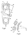
- Fig. 4 eine Untersicht einer Variante des Handapparats,
- Fig. 5 eine Chipkarte für den Handapparat,
- Fig. 6 eine Untersicht eines Handapparats mit schräg einführbarer Telefonchipkarte,
- Fig. 7 eine Draufsicht auf einen Führungsschlitten,
- Fig. 8 eine Darstellung zweier Positionen des beweglich gelagerten Führungsschlittens im Kartenaufnahmeraum, und
- Fig. 9 eine schematische Darstellung einer bevorzugten Bewegungskurve der auf der Chipkarte angeordneten Kontaktflächen.
- 1 is a bottom view of a handset according to the invention,
- 2 is a side view of the handset of FIG. 1,
- 3 is a top view of the handset of FIG. 1;
- 4 is a bottom view of a variant of the handset,
- 5 shows a chip card for the handset,
- 6 is a bottom view of a handset with an obliquely insertable telephone chip card,
- 7 is a plan view of a guide carriage,
- 8 shows two positions of the movably mounted guide carriage in the card receiving space, and
- Fig. 9 is a schematic representation of a preferred movement curve of the contact surfaces arranged on the chip card.
In den Zeichnungen sind gleiche Teile stets mit gleichen Bezugszeichen versehen.In the drawings, the same parts are always provided with the same reference numerals.
Der in Fig. 1 bis 3 dargestellte Handapparat (Handset) 1 ist für ein mit der in Fig. 5 dargestellten Telefonchipkarte 2 betreibbares Auto- oder Funktelefon bestimmt. Für die Verwendung als Autotelefon ist eine (nicht dargestellte) Auflage vorgesehen, auf welcher der Handapparat 1 verriegelbar ist, wobei die Verriegelung zum Abnehmen des Handapparats 1 mittels einer an der Auflage vorgesehenen Taste ausrückbar ist. Für die Verwendung als Funktelefon kann der Handapparat mit einem Sende- und Empfangsteil und einer Antenne (an der Stirnseite der Hörmuschel) ausgerüstet sein.The handset (handset) 1 shown in FIGS. 1 to 3 is intended for a car or radio telephone that can be operated with the
An der Gehäuseoberseite 5 ist der Handapparat mit einer Tastatur 6 und einem Anzeigefeld (Display) 7 versehen. An der Gehäuseunterseite 8 liegen die Hörmuschel 9 und die Sprechmuschel 10. (Unter "Muschel" werden die die Hör- bzw. Sprechkapsel 3 bzw. 4 beherbergenden Wandungsteile der Gehäuseunterseite verstanden.) Der die Hör- und Sprechmuschel 9 und 10 verbindende Griffteil des Gehäuses ist mit 11 bezeichnet, die beiden Gehäuselängsseiten mit 12 und 13.On the
An der Gehäuselängsseite 12 ist ein Einführungsschlitz 15 für die Telefonchipkarte 2 angeordnet. Die Länge des Einführungsschlitzes 15 ist um eine Toleranz grösser als die Länge der Chipkarte 2, so dass diese längsseitig einführbar ist. Der Einführungsschlitz 15 mündet in einen Kartenaufnahmeraum 16 für die Chipkarte 2, der sich bis zur Wandung der dem Einführungsschlitz 15 gegenüberliegenden Gehäuselängsseite 13 erstreckt. Die Breite des Kartenaufnahmeraums 16 entspricht also nahezu der Breite des Handapparats 1 und ist zur vollständigen Aufnahme der Karte 2 bemessen, so dass das Ergreifen und Halten des Handapparats 1 nicht durch einen aus dem Einführungsschlitz 15 herausragenden Kartenteil behindert ist.An
In Längsrichtung erstreckt sich der der Kartenlänge angepasste Kartenaufnahmeraum 16 etwa von der Mitte der Hörmuschel 9 bis ungefähr in die Mitte des Griffteils 11. Der grösste Teil des Kartenaufnahmeraums 16 befindet sich mithin im Griffteil 11, ein kleinerer Teil in der Hörmuschel 9, wobei der Aufnahmeraum über der Hörkapsel 3 liegt. Im Griffteil 11 ist der Kartenaufnahmeraum 16 unten durch die Wandung 18 der Gehäuseunterseite 8 begrenzt. Ueber dem Kartenaufnahmeraum 16 ist ein Chipkartenleser 17 zum Lesen der Chipkarte 2 angeordnet.In the longitudinal direction, the
Zum Herausschieben der vollständig in den Aufnahmeraum 16 eingeführten Chipkarte 2 ist in der Wandung 18 ein fingerbreites Langloch 19 vorgesehen, das quer zur Handapparatlängsrichtung verläuft. Das Langloch 19 ist so lang bemessen, dass die Karte 2 mit durch das Langloch greifendem (Zeige-)Finger in einer Bewegung längs des Langslochs soweit aus dem Einführungsschlitz 15 herausgeschoben werden kann, dass der daraus herausragende Kartenteil bequem gefasst und die Karte 2 ohne weiteres gänzlich herausgezogen werden kann.For pushing out the
Handelsübliche Telefonchipkarten haben eine glatte Oberfläche. Sie lassen sich deshalb nur mit Mühe in der angegebenen Weise lediglich mit aufgedrücktem Finger herausschieben, da der Finger auf der glatten Oberfläche abgleitet. Um das zu vermeiden, ist die Telefonchipkarte 2 in dem Bereich, der bei in den Kartenaufnahmeraum 16 eingeführter Karte 2 durch das Langloch 19 zugänglich ist, mit einer rutschfesten Oberfläche 20 versehen. Die rutschfeste Oberfläche 20 ist durch einen auf eine handelsübliche Chipkarte aufgebrachtes Gleitschutzmittel, beispielsweise ein auf die Karte geklebtes, rutschfestes Selbstklebeband gebildet.Commercial telephone chip cards have a smooth surface. They can therefore only be pushed out with difficulty in the manner indicated, only with an pressed finger, since the finger slides on the smooth surface. In order to avoid this, the
Der Chipkartenleser 17 ist in der üblichen Weise mit sog. "sliding" oder "landing" Kontakten ausgebildet und unterhalb der Tastatur 6 im Griffteil 11 angeordnet.The
Bei der in Fig. 3 dargestellten Variante ist eine mindestens fingerkappengrosse Randaussparung 21 am an den Karteneinführungsschlitz 15 angrenzenden Längsrandbereich 12 der Gehäuseunterseite 8 vorgesehen. Dies ermöglicht es, in einem Bewegungsablauf zunächst mit durch die Aussparung 21 greifendem Zeigefinger auf der in der Aussparung 21 zugänglichen Kartenoberfläche anzugreifen und die Karte 2 damit soweit aus dem Schlitz 15 herauszuschieben, dass anschliessend mit dem Daumen auf die andere Kartenoberfläche gefasst und die Karte 2 gänzlich herausgezogen werden kann.In the variant shown in FIG. 3, an
Zum gleichen Zweck kann sich bei der Ausführungsform von Fig. 1 und 2 das Langloch 19 auch bis in den Einführungsschlitz 15 hinein erstrecken.For the same purpose, in the embodiment of FIGS. 1 and 2, the
Die Aussparung 21 kann auch am dem Karteneinführungsschlitz 15 gegenüberliegenden Längsrandbereich 13 der Gehäuseunterseite 8 vorgesehen sein, so dass mit durch die Aussparung 21 greifendem Finger am dem Karteneinführungsschlitz 15 gegenüberliegenden Kartenlängsrand angegriffen und die Karte 2 soweit aus dem Schlitz 15 herausgestossen werden kann, dass ein zum Ergreifen ausreichender Kartenteil herausragt.The
Zum gleichen Zweck kann sich bei der Ausführungsform von Fig. 1 und 2 das Langloch 19 auch zum dem Karteneinführungsschlitz 15 gegenüberliegenden Längsrandbereich 13 der Gehäuseunterseite 8 hin erstrecken, soweit, dass mit dem Zeigefinger am dort liegenden Kartenrand angegriffen und die Karte um die Länge des Langlochs herausgestossen werden kann.For the same purpose, in the embodiment of FIGS. 1 and 2, the
Der Kartenaufnahmeraum 16 kann ferner auch an der Gehäuselängsseite 13 offen sein, so dass die Karte 2 wahlweise an jeder der beiden Gehäuseseiten 12, 13 herausziehbar ist. Dabei kann an der Längsseite 13 ebenfalls ein Einführungsschlitz 15 gebildet sein, um die Karte auch dort einführen zu können. Damit wird ein Durchschieben der Karte (Einführen und Herausziehen in derselben Richtung) von der einen und der anderen Seite ermöglicht.The
Der Chipkartenleser 17 kann so ausgebildet und angeordnet sein, dass die Chipkarte sowohl in der Gebrauchslage als auch in der umgedrehten (umgewendeten) Lage lesbar ist. Dazu kann der Kartenleser 17 in an sich bekannter Weise zum Lesen einer kontaktlosen Telefonchipkarte ausgebildet oder mit zwei oberhalb und unterhalb des Kartenaufnahmeraums 16 angeordneten Leseeinrichtungen ausgerüstet sein. Bei der dafür zu verwendenden Telefonchipkarte ist der Chip 22 im Bereich einer Mittelparallelen 23 der Karte 2 angeordnet, so dass das kontaktlose Lesen durch einen einzigen, über der Mittelparallelen 23 der im Kartenaufnahmeraum 16 befindlichen Karte 2 angeordneten induktiven Lesekopf erfolgen kann.The
Die rutschfeste Oberfläche 20 der Karte 2 kann auch mit Erhöhungen oder Vertiefungen, beispielsweise geriffelt ausgebildet sein, wobei die Riffelung bereits bei der Kartenherstellung oder nachträglich durch Pressen aufgebracht werden kann.The
Die beschriebenen Ausführungsformen des Handapparats und der Karte vereinigen im wesentlichen alle vorteilhaften Merkmale auf sich. Selbstverständlich ist es auch möglich, einzelne Merkmale wegzulassen und nur die im Einzelfall gewünschten Vorteile zu realisieren.The described embodiments of the handset and the card combine essentially all advantageous features. Of course, it is also possible to omit individual features and only realize the advantages desired in individual cases.
So lässt sich namentlich die erfindungsgemässe Ausnehmung 19, 21 auch unabhängig von der Anordnung des Einführungsschlitzes 15 an der Gehäuselängsseite 12 und der Bemessung des Schlitzes 15 nach der Kartenlänge realisieren. Insbesondere kann die erfindungsgemässe Ausnehmung 19, 21 und die rutschfeste Ausbildung der Kartenoberfläche sowie die Ausbildung des Kartenlesers zum Lesen auch einer umgewendet eingeführten Karte bei stirnseitig (an der Stirnseite der Hörmuschel 9 oder der Sprechmuschel 10) angeordnetem Einführungsschlitz und bei einer Schlitzbemessung nach der Kartenbreite zum schmalseitigen Einführen der Karte vorteilhaft realisiert werden.In particular, the
Im folgenden werden vorteilhafte Ausführungsformen zur praktischen Realisierung des Längseinschubs in Verbindung mit bekannten normierten Chipkarten beschrieben.In the following, advantageous embodiments for the practical implementation of the longitudinal insertion are described in connection with known standardized chip cards.
Fig. 6 zeigt einen Handapparat 24, der in seiner äusseren Erscheinungsform z. B. dem in Fig. 1 gezeigten entsprechen kann. Andeutungsweise sind eine Hörmuschel 25 und eine Sprechmuschel 26 eingezeichnet. Ein Kartenaufnahmeraum 27 weist einen Einführungsschlitz 31 auf, der an der Gehäuselängsseite des Handapparats angeordnet ist. Er ist im vorliegenden Fall eindeutig länger als die einzuführende Telefonchipkarte 30. Im Kartenaufnahmeraum 27 ist ein Führungsschlitten 28 drehbar gelagert. Rotationsachse ist gemäss einer besonders bevorzugten Ausführungsform eine Achse 29, die in einem Randbereich der im Führungsschlitten 28 eingeführten Telefonchipkarte 30, insbesondere in der Nähe einer Ecke derselben angeordnet ist. Um diese Achse 29 ist der Führungsschlitten 28 zwischen einer Kartenaufnahmeposition und einer Kontaktposition hin und her bewegbar. Die Kontaktposition ist vorzugsweise dadurch definiert, dass die Telefonchipkarte 30 mit ihrer Längsseite parallel zur Gehäuselängsseite des Handapparats resp. zum Einführungsschlitz 31 liegt. In der Kartenaufnahmeposition ist der Führungsschlitten im vorliegenden Beispiel um etwa 20° im Uhrzeigersinn gedreht. Wie weiter unten noch zu erläutern sein wird, soll der Winkel möglichst klein sein.Fig. 6 shows a
Das Einführen der Telefonchipkarte 30 läuft wie folgt ab: Die Chipkarte 30 wird leicht schräg d. h. mit einer Ecke voran in den Einführungsschlitz 31 eingeschoben in Richtung senkrecht zur Kantenlängsseite. Der Führungsschlitten 28 weist geeignete Führungsmittel auf, so dass die Karte in einer Richtung senkrecht zur Längsseite geführt wird. Wenn die Karte vollständig im Führungsschlitten 28 sitzt, befindet sie sich noch nicht vollständig im Kartenaufnahmeraum 27, sondern ragt noch mit einer Ecke aus diesem heraus.The insertion of the
Der Führungsschlitten 28 ist in der Kartenaufnahmeposition blockiert, damit er sich nicht bewegen kann, wenn die Telefonchipkarte 30 in der oben beschriebenen Art eingeschoben wird. Sobald letztere aber korrekt im Führungsschlitten 28 sitzt, wird ein Kontaktschalter aktiviert, der die Deblokkierung der Drehbewegung einleitet. Entweder durch Druck des Benutzers auf die herausragende Kartenecke oder mit Hilfe eines internen Antriebs wird der Führungsschlitten 28 mit der darin einsitzenden Telefonchipkarte 30 um die Achse 29 gedreht. Beim Erreichen der Kontaktposition resp. kurz davor kommt es zum elektrischen Kontakt zwischen den auf der Karte normiert angeordneten Kontaktflächen und den Kontaktelementen des Handapparats. Erst wenn der elektrische Kontakt sichergestellt ist, kann der auf der Chipkarte integrierte Halbleiterspeicher oder Prozessor angesteuert werden. Nach Abschluss der Kommunikation zwischen Handapparat und Chipkarte kann letztere wieder ausgeworfen resp. vom Benutzer herausgezogen werden (vgl. dazu Langloch 19 aus Fig. 1 und Aussparung 21 aus Fig. 4).The
Im folgenden soll auf ein paar vorteilhafte konstruktive Einzelheiten eingegangen werden.In the following, a few advantageous structural details will be discussed.
Fig. 7 zeigt eine Draufsicht auf den Führungsschlitten 28. Dieser ist im wesentlichen trapezförmig, d. h. er weist zwei parallele Schmalseiten 34, 35, eine abgeschrägte Vorderseite 32 und eine Hinterseite 33 auf. Die Hinterseite 33 bildet mit den beiden parallelen Schmalseiten 34 und 35 im wesentlichen einen rechten Winkel. Die schräge Vorderseite bildet mit der Schmalseite 24 einen spitzen und mit der Schmalseite 35 einen stumpfen Winkel.FIG. 7 shows a top view of the
An den Schmalseiten 34 und 35 sind z. B. einander zugewandte Führungsrillen 36 und 37 angeformt, welche die einzuführende Telefonchipkarte an deren Schmalseiten umgreifen und führen können. An der Schmalseite 35 kann ein Federelement 38 vorgesehen sein, das dafür sorgt, dass die Telefonchipkarte stets in der gleichen wohldefinierten Weise im Führungsschlitten 28 sitzt.On the
Ein Arretierelement 39 an der Hinterseite des Führungsschlittens 28 stoppt die lineare Einschubbewegung der Karte ab.A locking
An der spitzwinkligen Ecke zwischen der Schmalseite 34 und der Vorderseite 32 ist ein Gelenkteil 40 angeformt. Er ist im vorliegenden Beispiel in der Art eines Ringes ausgebildet, der eine ortsfeste Drehachse des Handapparats zu umschliessen hat.A
Gemäss einer bevorzugten Ausführungsform der Erfindung ist die Vorderseite 32 gerade so abgeschrägt, dass sie parallel zum Einführungsschlitz 31 des Kartenaufnahmeraums 27 steht, wenn der Führungsschlitten 28 in der Kartenaufnahmeposition ist. Die Abweichung des spitzen Winkels zwischen der Schmalseite 34 und der Vorderseite 32 von einem rechten Winkel entspricht dann gerade dem Schwenkwinkel zwischen Kartenaufnahmeposition und Kontaktposition des Führungsschlittens 28.According to a preferred embodiment of the invention, the
Damit die Chipkarte mit geringer Toleranz im Führungsschlitten 28 festgehalten werden kann, sollten beide Schmalseiten 34 und 35 und damit auch die Führungsrillen möglichst lang sein. Dies ist dann der Fall, wenn die Vorderseite 32 möglichst wenig geneigt ist. Diese Neigung bemisst sich wie oben erläutert vorzugsweise nach dem Schwenkwinkel des Führungsschlittens. Es folgt somit, dass die präzise Führung der Telefonchipkarte durch einen möglichst geringen Schwenkwinkel des Führungsschlittens begünstigt wird.So that the chip card can be held in the
Fig. 8 veranschaulicht den oben beschriebenen Vorgang beim Einschieben der Telefonchipkarte in den Handapparat. Es sind zwei unterschiedliche Positionen des Führungsschlittens 28 mit der darin eingeführten Telefonchipkarte 30 gezeigt. Um die beiden Positionen voneinander unterscheiden zu können, sind in der Fig. die Bezugszahlen mit den Kleinbuchstaben "a" und "b" ergänzt worden. Die Endbewegung gemäss der Erfindung findet beim Uebergang von der leicht schrägen Position "a" in die gerade Position "b" statt. Der Führungsschlitten 28 dreht sich dabei um die Achse 29. Der Drehwinkel beträgt z. B. 5 bis 10°. Während in der schrägen Position die Vorderseite 32a parallel zum Einführungsschlitz ist, ist in der Kontaktposition die Hinterseite 33b parallel zum Einführungsschlitz.Fig. 8 illustrates the process described above when inserting the telephone chip card into the handset. Two different positions of the
In bezug auf die Länge des Einführungsschlitzes ist zu beachten, dass diese nicht viel grösser als die Länge der Telefonchipkarte zu sein braucht, da der Rotationswinkel nur sehr klein ist.With regard to the length of the insertion slot, it should be noted that this does not have to be much larger than the length of the telephone chip card, since the angle of rotation is only very small.
Interessant ist nun, wie die sechs standardisierten Kontaktflächen 41.1, ..., 41.6 der Telefonchipkarte auf die Kontaktelemente 42.1, ..., 42.6 hingeführt werden.It is now interesting to see how the six standardized contact areas 41.1, ..., 41.6 of the telephone chip card are led to the contact elements 42.1, ..., 42.6.
Die Kontaktelemente 42.1, ..., 42.6 sind z. B. mit an sich bekannten Kontaktfedern verwirklicht. Diese haben eine bevorzugte Belastungsrichtung. D. h. es gibt eine Richtung, in welcher sie besonders gut und problemlos auf einer Kontaktfläche verschoben werden können. Senkrecht zu dieser bevorzugten Richtung sind sie weniger stabil und viel leichter verletzlich.The contact elements 42.1, ..., 42.6 are z. B. realized with contact springs known per se. These have a preferred direction of loading. That is, there is a direction in which they are particularly good and easy on a contact surface can be moved. Perpendicular to this preferred direction, they are less stable and much more vulnerable.
Beim Drehen des Führungsschlittens gleiten nun diese Kontaktelemente über die Kartenoberfläche resp. die Kontaktflächen 41.1, ..., 41.6. Werden die an sich bekannten federnden Kontaktelemente eingesetzt, so sind sie so ausgerichtet, dass die bevorzugte Richtung im wesentlichen identisch mit der Längsrichtung des Handapparats resp. der in Kontaktposition befindlichen Telefonchipkarte ist. Beim Schliessen resp. Lösen des elektrischen Kontakts dreht sich die Telefonchipkarte auf einer wegen des grossen Abstandes der Achse 29 zu den Kontaktflächen schwach gekrümmten Bahn unter die Kontaktelemente 42.1, ..., 42.6 resp. von ihnen weg. Die Endbewegung verläuft also zumindest näherungsweise vorwiegend in Längsrichtung.When turning the guide carriage, these contact elements now slide over the card surface, respectively. the contact areas 41.1, ..., 41.6. If the known resilient contact elements are used, they are aligned so that the preferred direction is essentially identical to the longitudinal direction of the handset, respectively. the phone chip card in contact position. When closing or Releasing the electrical contact turns the phone chip card on a slightly curved path because of the large distance between the
Ein weiteres wichtiges Argument zugunsten der erfindungsgemässen Endbewegung stellt der grössere Zeitraum dar, der beim Lösen der elektrischen Kontakte zur Verfügung steht. In der Regel wird die Karte erst dann herausgenommen, wenn die Kommunikation zwischen dem Handapparat und der integrierten Schaltung auf der Telefonchipkarte abgeschlossen ist (d. h. wenn das Telefongespräch beendet ist). Grundsätzlich ist es aber auch möglich, dass der Benutzer die Karte vorzeitig aus dem Kartenaufnahmeraum herausnimmt. Auch in diesem sehr ungünstigen Fall muss gewährleistet sein, dass der Chip auf der Karte nicht in einem undefinierten Zustand zurückgelassen werden kann.Another important argument in favor of the final movement according to the invention is the longer period that is available when the electrical contacts are released. Typically, the card is not removed until the communication between the handset and the integrated circuit on the phone chip card is complete (i.e., when the phone call is ended). In principle, however, it is also possible for the user to take the card out of the card receiving space prematurely. Even in this very unfavorable case, it must be ensured that the chip cannot be left in an undefined state on the card.
Eine Möglichkeit, diesen Sicherheitsanforderungen zu entsprechen, besteht darin, dass ein Kontaktschalter ein Herausnehmen der Telefonchipkarte unverzüglich detektiert und dass der Kommunikationsprozessor unverzüglich einen definierten Schlussstatus des Kartenchips herbeiführt. Dies kann aufgrund der hohen Taktrate heutiger integrierter Prozessoren grundsätzlich innerhalb von Millisekunden erreicht werden. Allerdings ist damit zu rechnen, dass vom Beginn der unerwünschten Kartenbewegung bis zum Abschluss der Datenkommunikation eine gewisse minimale Zeit verstreicht. Diese Verzögerungszeit wird aufgrund der erfindungsgemässen Anordnung wie folgt erzeugt.One way to meet these security requirements is for a contact switch to detect the removal of the telephone chip card immediately and that the communication processor immediately brings about a defined final status of the card chip. Due to the high clock rate of today's integrated processors, this can basically be achieved within milliseconds. However, it can be expected that a certain minimum time will elapse from the start of the undesired card movement to the end of the data communication. This delay time is generated as follows on the basis of the arrangement according to the invention.
Die Kontaktelemente 42.1, ..., 42.6 schleifen (aufgrund ihrer federnden Lagerung) in der Endbewegungsphase über die Kartenoberfläche und insbesondere über die Kontaktflächen 41.1, ..., 41.6. Gemäss der gegenwärtig üblichsten Norm haben die Kontaktflächen 41.1, ..., 41.6 je eine rechteckige Form mit einer Kantenlänge von 2.0 x 1.6 Millimetern. Wenn sich die Telefonchipkarte in der Kontaktposition "b" befindet, dann sind die Längsseiten parallel zum Einführungsschlitz.The contact elements 42.1, ..., 42.6 rub (due to their resilient mounting) in the final movement phase over the card surface and in particular over the contact surfaces 41.1, ..., 41.6. According to the currently most common standard, the contact surfaces 41.1, ..., 41.6 each have a rectangular shape with an edge length of 2.0 x 1.6 millimeters. When the telephone chip card is in the contact position "b", the long sides are parallel to the insertion slot.
Wie bereits mehrfach erwähnt, verläuft die Bewegung in der Endphase (beim Einführen) resp. der Anfangsphase (beim Herausdrehen) näherungsweise tangential zur Längsrichtung der Kontaktflächen 41.1, ..., 41.6 resp. senkrecht zu einer Querachse 43 des Handapparats. Auch wenn die Telefonchipkarte aus ihrer Kontaktposition herausgedreht wird, bleibt der elektrische Kontakt zwischen den Kontaktflächen 41.1, ..., 41.6 und den Kontaktelementen 42.1, ..., 42.6 noch über eine gewisse Strecke hinweg bestehen. Die Zeit, die nun zum Durchlaufen dieser Strecke benötigt wird, bestimmt die zur Verfügung stehende Verzögerungszeit.As already mentioned several times, the movement takes place in the final phase (when inserting). the initial phase (when unscrewing) approximately tangential to the longitudinal direction of the contact surfaces 41.1, ..., 41.6, respectively. perpendicular to a
Es leuchtet ein, dass bei einem reinen längsseitigen Einschub (vollständig lineare Bewegung senkrecht zur Längsseite der Telefonchipkarte) die nutzbare Verzögerungszeit kleiner ist, weil die genormten Kontaktflächen nur etwa 1.6 Millimeter breit sind. Zudem sind die Kontaktflächen seitlich viel näher beabstandet als in Längsrichtung. Der seitliche Raster beträgt nämlich etwa 2.54 Millimeter. In Längsrichtung ist dagegen allein schon die Distanz ein Mehrfaches der Länge einer einzigen Kontaktfläche.It makes sense that with a purely longitudinal insertion (completely linear movement perpendicular to the long side of the telephone chip card) the usable delay time is shorter because the standardized contact areas are only about 1.6 millimeters wide. In addition, the contact surfaces are laterally much closer than in the longitudinal direction. The lateral grid is about 2.54 millimeters. In the longitudinal direction, however, the distance alone is a multiple of the length of a single contact area.
Aufgrund des oben Gesagten leuchtet es ein, dass der Drehwinkel nur gerade so gross zu sein braucht, dass die Kontaktflächen 41.1, ..., 41.6 alle vollständig von den Kontaktelementen 42.1, ..., 42.6 lateral getrennt sind. Wie gross der Winkel im Einzelfall zu sein braucht, hängt davon ab, wo die Drehachse angeordnet ist. Vorteilhaft ist einerseits ein grosser Abstand von den Kontaktelementen 42.1, ..., 42.6 (was einen grossen Drehradius ergibt) und andererseits eine Anordnung möglichst "auf gleicher Höhe" wie die Kontaktelemente, damit die Endbewegung möglichst gut einer Längsbewegung im oben erläuterten Sinn entspricht.On the basis of what has been said above, it is clear that the angle of rotation need only be so large that the contact surfaces 41.1, ..., 41.6 are all completely laterally separated from the contact elements 42.1, ..., 42.6. How large the angle needs to be in individual cases depends on where the axis of rotation is located. It is advantageous on the one hand to have a large distance from the contact elements 42.1, ..., 42.6 (which results in a large turning radius) and on the other hand to arrange them as "as possible" as the contact elements so that the final movement corresponds as well as possible to a longitudinal movement in the sense explained above.
Anhand von Fig. 9 soll gezeigt werden, was unter dem Begriff "auf gleicher Höhe" zu verstehen ist. Fig. 9 zeigt schematisch zwei Kontaktflächen 41.1 und 41.2 und zwei Kontaktelemente 42.1 und 42.2. Dem Kontaktelement 42.1 kann eine Längsachse 47 und eine Querachse 48 zugeordnet werden. Wenn nun der Führungsschlitten so ausgebildet ist, dass er sich um eine Rotationsachse 46 bewegt, die auf oder zumindest in der Nähe der Querachse 48 liegt, dann verläuft die Endbewegung der Kontaktfläche 41.1 weitgehend tangential zur Längsachse 47. Je grösser der Rotationsradius R ist, desto schwächer ist die Bewegungskurve gekrümmt.9 shows what is to be understood by the term “at the same level”. 9 schematically shows two contact surfaces 41.1 and 41.2 and two contact elements 42.1 and 42.2. A
Die in der Fig. 8 gezeigte und an sich bestens bekannte und auch genormte Anordnung der Kontaktflächen 41.1, ..., 41.6 umfasst im Prinzip zwei Dreiergruppen von auf einer gemeinsamen Querachse angeordneten Kontaktflächen 41.1, 41.2, 41.3 resp. 41.4, 41.5, 41.6.The arrangement of the contact surfaces 41.1,..., 41.6 shown in FIG. 8, which is well known and also known per se, is also standardized in principle comprises two groups of three of contact surfaces 41.1, 41.2, 41.3 arranged on a common transverse axis. 41.4, 41.5, 41.6.
Der Begriff "auf gleicher Höhe" ist nun so zu verstehen, dass die Rotationsachse zwischen den beiden gemeinsamen Querachsen oder in unmittelbarer Nähe davon angeordnet ist. Vorteilhaft ist es deshalb, wenn die Rotationsachse am Rand der Vorderseite des Führungsschlittens in der Umgebung der genannten Querachsen angeordnet ist. Die geometrische Verlängerung der Rotationsachse durchstösst also die geometrische Ebene der im Führungsschlitten sitzenden Telefonchipkarte in der Nähe ihres Randes, insbesondere einer ihrer Längsseiten.The term "at the same height" is now to be understood such that the axis of rotation is arranged between the two common transverse axes or in the immediate vicinity thereof. It is therefore advantageous if the axis of rotation is arranged on the edge of the front of the guide carriage in the vicinity of the transverse axes mentioned. The geometric extension of the axis of rotation thus penetrates the geometric plane of the telephone chip card seated in the guide carriage near its edge, in particular one of its long sides.
Gemäss einer bevorzugten Ausführungsform der Erfindung wird der Führungsschlitten in seiner zur Aufnahme der Telefonchipkarte bereiten Position so lange blockiert, bis die Karte vollständig in den Führungsschlitten eingeschoben ist und infolgedessen einen Kontakthebel 49 (vgl. Fig. 7) betätigt. Danach wird die Deblockierung der Drehbewegung eingeleitet. Sobald die Kontaktflächen 41.1, ..., 41.6 der Chipkarte mit den Kontaktelementen 42.1, ..., 42.6 elektrisch Kontakt machen können, kann die Kommunikation zwischen der Telefonchipkarte und dem Handapparat beginnen. Das Vorliegen eines ausreichenden Kontakts kann durch einen Näherungsschalter 45 ermittelt werden, der die Annäherung eines Referenzelementes 44 des Führungsschlittens detektiert (Uebergang von der Position 44a auf die Position 44b).According to a preferred embodiment of the invention, the guide carriage is blocked in its position ready to receive the telephone chip card until the card is completely inserted into the guide carriage and, as a result, a contact lever 49 (cf. FIG. 7) is actuated. Then the unblocking of the rotary movement is initiated. As soon as the contact surfaces 41.1, ..., 41.6 of the chip card can make electrical contact with the contact elements 42.1, ..., 42.6, the communication between the telephone chip card and the handset can begin. The presence of sufficient contact can be determined by a
Die erfindungsgemässe Idee, einen längsseitigen Einschub mit einer vorzugsweise rotierenden Endbewegung zu kombinieren, kann auch anders als in den Figuren gezeigt realisiert werden. Insbesondere die konstruktiven Einzelheiten sind nicht beschränkend auszulegen.The inventive idea of combining a longitudinal insertion with a preferably rotating end movement can also be realized differently than shown in the figures. In particular, the design details are not to be interpreted restrictively.
Beispielsweise kann die rotative Bewegung resp. Lagerung durch irgendwelche scharnierartig zusammenwirkende Gelenkteile verwirklicht werden. Es kann aber auch eine geeignete Kulisse, in welcher der Führungsschlitten gleitet, im Kartenaufnahmeraum ausgebildet sein.For example, the rotary movement or Storage can be realized by any hinge-like interacting joint parts. However, a suitable backdrop, in which the guide slide slides, can also be formed in the card receiving space.
In Fig. 8 wird die Drehung um eine zwar unmittelbar am Rand der eingefügten Telefonchipkarte, aber "ausserhalb derselben liegenden" Achse durchgeführt. Selbstverständlich ist es auch möglich, oder unter Umständen sogar sinnvoll, die Rotationsachse "innerhalb der Karte" anzuordnen.In Fig. 8 the rotation is carried out about an axis which is located directly on the edge of the inserted telephone chip card, but "outside the same". Of course, it is also possible, or possibly even sensible, to arrange the axis of rotation "within the map".
Es darf natürlich nicht vergessen werden, dass das Grundprinzip der Erfindung (längsseitiger Einschub) auch mit einer rein translatorischen Bewegung d. h. ohne gekrümmte Endbewegung verwirklicht werden kann.It should of course not be forgotten that the basic principle of the invention (longitudinal insertion) also with a purely translational movement d. H. can be realized without a curved end movement.
Schliesslich ist es auch denkbar, den Führungsschlitten wegzulassen und die Karte unmittelbar in einer Kulisse gleiten zu lassen.Finally, it is also conceivable to omit the guide carriage and to slide the card directly against a backdrop.
Claims (23)
Applications Claiming Priority (2)
| Application Number | Priority Date | Filing Date | Title |
|---|---|---|---|
| CH72191 | 1991-03-11 | ||
| CH721/91 | 1991-03-11 |
Publications (3)
| Publication Number | Publication Date |
|---|---|
| EP0508944A2 true EP0508944A2 (en) | 1992-10-14 |
| EP0508944A3 EP0508944A3 (en) | 1993-07-14 |
| EP0508944B1 EP0508944B1 (en) | 1999-05-26 |
Family
ID=4193640
Family Applications (1)
| Application Number | Title | Priority Date | Filing Date |
|---|---|---|---|
| EP19920810178 Expired - Lifetime EP0508944B1 (en) | 1991-03-11 | 1992-03-10 | Handset for a card operated car telephone or radiotelephone |
Country Status (2)
| Country | Link |
|---|---|
| EP (1) | EP0508944B1 (en) |
| DE (2) | DE9109087U1 (en) |
Cited By (2)
| Publication number | Priority date | Publication date | Assignee | Title |
|---|---|---|---|---|
| US5353328A (en) * | 1992-02-14 | 1994-10-04 | Nokia Mobile Phones Ltd. | Data adapter for a radiotelephone |
| WO1999066694A1 (en) * | 1998-06-15 | 1999-12-23 | Lindholm Ventola Jukka | Casing of a mobile telephone or of other similar device and self adhesive label attachable to the outer surface of these devices |
Families Citing this family (2)
| Publication number | Priority date | Publication date | Assignee | Title |
|---|---|---|---|---|
| DE9109087U1 (en) * | 1991-03-11 | 1991-11-14 | Peiker, Andreas, Dipl.-Ing., 6380 Bad Homburg, De | |
| DE10049965A1 (en) * | 2000-10-10 | 2002-05-02 | Ameur Raouf Ben | Security device fitted into mobile telephone or motor vehicle, comprises anti-theft apparatus with chip card and communication interfaces for wireless communication |
Citations (4)
| Publication number | Priority date | Publication date | Assignee | Title |
|---|---|---|---|---|
| DE3610202A1 (en) * | 1985-04-01 | 1986-10-09 | Heinrich Andreas 6380 Bad Homburg Peiker | Handset, in particular for a car phone |
| DE8703864U1 (en) * | 1987-02-24 | 1987-07-30 | Nokia-Mobira Oy, Salo, Fi | |
| EP0319108A2 (en) * | 1987-12-03 | 1989-06-07 | Philips Patentverwaltung GmbH | Hand set, particularly for a radiotelephone |
| DE9109087U1 (en) * | 1991-03-11 | 1991-11-14 | Peiker, Andreas, Dipl.-Ing., 6380 Bad Homburg, De |
-
1991
- 1991-07-24 DE DE9109087U patent/DE9109087U1/de not_active Expired - Lifetime
-
1992
- 1992-03-10 EP EP19920810178 patent/EP0508944B1/en not_active Expired - Lifetime
- 1992-03-10 DE DE59209697T patent/DE59209697D1/en not_active Expired - Fee Related
Patent Citations (4)
| Publication number | Priority date | Publication date | Assignee | Title |
|---|---|---|---|---|
| DE3610202A1 (en) * | 1985-04-01 | 1986-10-09 | Heinrich Andreas 6380 Bad Homburg Peiker | Handset, in particular for a car phone |
| DE8703864U1 (en) * | 1987-02-24 | 1987-07-30 | Nokia-Mobira Oy, Salo, Fi | |
| EP0319108A2 (en) * | 1987-12-03 | 1989-06-07 | Philips Patentverwaltung GmbH | Hand set, particularly for a radiotelephone |
| DE9109087U1 (en) * | 1991-03-11 | 1991-11-14 | Peiker, Andreas, Dipl.-Ing., 6380 Bad Homburg, De |
Cited By (2)
| Publication number | Priority date | Publication date | Assignee | Title |
|---|---|---|---|---|
| US5353328A (en) * | 1992-02-14 | 1994-10-04 | Nokia Mobile Phones Ltd. | Data adapter for a radiotelephone |
| WO1999066694A1 (en) * | 1998-06-15 | 1999-12-23 | Lindholm Ventola Jukka | Casing of a mobile telephone or of other similar device and self adhesive label attachable to the outer surface of these devices |
Also Published As
| Publication number | Publication date |
|---|---|
| DE9109087U1 (en) | 1991-11-14 |
| DE59209697D1 (en) | 1999-07-01 |
| EP0508944B1 (en) | 1999-05-26 |
| EP0508944A3 (en) | 1993-07-14 |
Similar Documents
| Publication | Publication Date | Title |
|---|---|---|
| DE19540104C2 (en) | Electrical connector and its use | |
| DE69931049T2 (en) | DEVICE FOR MOUNTING AND DISCONNECTING SIM CARDS | |
| DE60103710T2 (en) | Plug-in card with extendable antenna for portable electronic devices | |
| DE4320683C2 (en) | Portable information processing device | |
| DE602006000986T2 (en) | Memory card socket structure | |
| DE4034678C2 (en) | ||
| DE3202837A1 (en) | "BATTERY CONTAINER" | |
| DE60119235T2 (en) | Telecommunication card with integrated antenna | |
| WO1991015101A1 (en) | Contactor device, especially for an sim | |
| DE3642424A1 (en) | INFORMATION PROCESSING DEVICE FOR IC CARDS | |
| DE3937383A1 (en) | RECEIVING DEVICE FOR CHIP CARDS | |
| DE10324295A1 (en) | Multi-function miniature electric switch has central operating button for providing confirmation function having diametrically opposing arms for providing selection functions | |
| DE60103934T2 (en) | COMMUNICATIONS DEVICE | |
| DE1302495B (en) | ||
| EP2130609B1 (en) | Discharge device for media | |
| DE3822848C2 (en) | Handheld radio phone | |
| DE2739593B2 (en) | Handy control device, especially for video games, with a pivotable, rotatable and displaceable operating part | |
| DE60126201T2 (en) | Electrical card connector | |
| EP0508944A2 (en) | Handset for a card operated car telephone or radiotelephone and telephone card for such a handset | |
| EP0731415B1 (en) | Case for a chipcard | |
| DE3515434C2 (en) | ||
| DE69832343T2 (en) | Mechanism for throwing out in two stages | |
| DE2438046B2 (en) | BROADCASTING RECEIVER | |
| DE3238723A1 (en) | RADIO FOR A SENDING, RECEIVING AND READY MODE | |
| DE10332583B4 (en) | Card connector assembly |
Legal Events
| Date | Code | Title | Description |
|---|---|---|---|
| PUAI | Public reference made under article 153(3) epc to a published international application that has entered the european phase |
Free format text: ORIGINAL CODE: 0009012 |
|
| AK | Designated contracting states |
Kind code of ref document: A2 Designated state(s): CH DE FR IT LI |
|
| PUAL | Search report despatched |
Free format text: ORIGINAL CODE: 0009013 |
|
| AK | Designated contracting states |
Kind code of ref document: A3 Designated state(s): CH DE FR IT LI |
|
| 17P | Request for examination filed |
Effective date: 19931202 |
|
| 17Q | First examination report despatched |
Effective date: 19961219 |
|
| GRAG | Despatch of communication of intention to grant |
Free format text: ORIGINAL CODE: EPIDOS AGRA |
|
| GRAG | Despatch of communication of intention to grant |
Free format text: ORIGINAL CODE: EPIDOS AGRA |
|
| GRAH | Despatch of communication of intention to grant a patent |
Free format text: ORIGINAL CODE: EPIDOS IGRA |
|
| GRAH | Despatch of communication of intention to grant a patent |
Free format text: ORIGINAL CODE: EPIDOS IGRA |
|
| GRAA | (expected) grant |
Free format text: ORIGINAL CODE: 0009210 |
|
| AK | Designated contracting states |
Kind code of ref document: B1 Designated state(s): CH DE FR IT LI |
|
| REG | Reference to a national code |
Ref country code: CH Ref legal event code: NV Representative=s name: KELLER & PARTNER PATENTANWAELTE AG Ref country code: CH Ref legal event code: EP |
|
| REF | Corresponds to: |
Ref document number: 59209697 Country of ref document: DE Date of ref document: 19990701 |
|
| ET | Fr: translation filed | ||
| PLBE | No opposition filed within time limit |
Free format text: ORIGINAL CODE: 0009261 |
|
| STAA | Information on the status of an ep patent application or granted ep patent |
Free format text: STATUS: NO OPPOSITION FILED WITHIN TIME LIMIT |
|
| 26N | No opposition filed | ||
| PGFP | Annual fee paid to national office [announced via postgrant information from national office to epo] |
Ref country code: CH Payment date: 20060217 Year of fee payment: 15 |
|
| PGFP | Annual fee paid to national office [announced via postgrant information from national office to epo] |
Ref country code: IT Payment date: 20060331 Year of fee payment: 15 |
|
| REG | Reference to a national code |
Ref country code: CH Ref legal event code: PL |
|
| PG25 | Lapsed in a contracting state [announced via postgrant information from national office to epo] |
Ref country code: CH Free format text: LAPSE BECAUSE OF NON-PAYMENT OF DUE FEES Effective date: 20070331 Ref country code: LI Free format text: LAPSE BECAUSE OF NON-PAYMENT OF DUE FEES Effective date: 20070331 |
|
| PGFP | Annual fee paid to national office [announced via postgrant information from national office to epo] |
Ref country code: DE Payment date: 20080220 Year of fee payment: 17 |
|
| PG25 | Lapsed in a contracting state [announced via postgrant information from national office to epo] |
Ref country code: IT Free format text: LAPSE BECAUSE OF NON-PAYMENT OF DUE FEES Effective date: 20070310 |
|
| PGFP | Annual fee paid to national office [announced via postgrant information from national office to epo] |
Ref country code: FR Payment date: 20090226 Year of fee payment: 18 |
|
| PG25 | Lapsed in a contracting state [announced via postgrant information from national office to epo] |
Ref country code: DE Free format text: LAPSE BECAUSE OF NON-PAYMENT OF DUE FEES Effective date: 20091001 |
|
| REG | Reference to a national code |
Ref country code: FR Ref legal event code: ST Effective date: 20101130 |
|
| PG25 | Lapsed in a contracting state [announced via postgrant information from national office to epo] |
Ref country code: FR Free format text: LAPSE BECAUSE OF NON-PAYMENT OF DUE FEES Effective date: 20100331 |