EP0509969A1 - A lever control for electrical equipment in a motor vehicle - Google Patents
A lever control for electrical equipment in a motor vehicle Download PDFInfo
- Publication number
- EP0509969A1 EP0509969A1 EP92830182A EP92830182A EP0509969A1 EP 0509969 A1 EP0509969 A1 EP 0509969A1 EP 92830182 A EP92830182 A EP 92830182A EP 92830182 A EP92830182 A EP 92830182A EP 0509969 A1 EP0509969 A1 EP 0509969A1
- Authority
- EP
- European Patent Office
- Prior art keywords
- casing
- teeth
- lever
- ring
- relative
- Prior art date
- Legal status (The legal status is an assumption and is not a legal conclusion. Google has not performed a legal analysis and makes no representation as to the accuracy of the status listed.)
- Ceased
Links
Images
Classifications
-
- G—PHYSICS
- G05—CONTROLLING; REGULATING
- G05G—CONTROL DEVICES OR SYSTEMS INSOFAR AS CHARACTERISED BY MECHANICAL FEATURES ONLY
- G05G5/00—Means for preventing, limiting or returning the movements of parts of a control mechanism, e.g. locking controlling member
- G05G5/12—Means for preventing, limiting or returning the movements of parts of a control mechanism, e.g. locking controlling member for holding members in an indefinite number of positions, e.g. by a toothed quadrant
-
- B—PERFORMING OPERATIONS; TRANSPORTING
- B60—VEHICLES IN GENERAL
- B60Q—ARRANGEMENT OF SIGNALLING OR LIGHTING DEVICES, THE MOUNTING OR SUPPORTING THEREOF OR CIRCUITS THEREFOR, FOR VEHICLES IN GENERAL
- B60Q1/00—Arrangement of optical signalling or lighting devices, the mounting or supporting thereof or circuits therefor
- B60Q1/02—Arrangement of optical signalling or lighting devices, the mounting or supporting thereof or circuits therefor the devices being primarily intended to illuminate the way ahead or to illuminate other areas of way or environments
- B60Q1/04—Arrangement of optical signalling or lighting devices, the mounting or supporting thereof or circuits therefor the devices being primarily intended to illuminate the way ahead or to illuminate other areas of way or environments the devices being headlights
- B60Q1/14—Arrangement of optical signalling or lighting devices, the mounting or supporting thereof or circuits therefor the devices being primarily intended to illuminate the way ahead or to illuminate other areas of way or environments the devices being headlights having dimming means
- B60Q1/1446—Arrangement of optical signalling or lighting devices, the mounting or supporting thereof or circuits therefor the devices being primarily intended to illuminate the way ahead or to illuminate other areas of way or environments the devices being headlights having dimming means controlled by mechanically actuated switches
- B60Q1/1453—Hand actuated switches
- B60Q1/1461—Multifunction switches for dimming headlights and controlling additional devices, e.g. for controlling direction indicating lights
- B60Q1/1469—Multifunction switches for dimming headlights and controlling additional devices, e.g. for controlling direction indicating lights controlled by or attached to a single lever, e.g. steering column stalk switches
- B60Q1/1476—Multifunction switches for dimming headlights and controlling additional devices, e.g. for controlling direction indicating lights controlled by or attached to a single lever, e.g. steering column stalk switches comprising switch controlling means located near the free end of the lever, e.g. press buttons, rotatable rings
-
- G—PHYSICS
- G05—CONTROLLING; REGULATING
- G05G—CONTROL DEVICES OR SYSTEMS INSOFAR AS CHARACTERISED BY MECHANICAL FEATURES ONLY
- G05G1/00—Controlling members, e.g. knobs or handles; Assemblies or arrangements thereof; Indicating position of controlling members
- G05G1/04—Controlling members for hand actuation by pivoting movement, e.g. levers
-
- H—ELECTRICITY
- H01—ELECTRIC ELEMENTS
- H01H—ELECTRIC SWITCHES; RELAYS; SELECTORS; EMERGENCY PROTECTIVE DEVICES
- H01H9/00—Details of switching devices, not covered by groups H01H1/00 - H01H7/00
- H01H9/02—Bases, casings, or covers
- H01H9/0207—Adjustable mounting of casings
Definitions
- the present invention relates to a lever control for controlling electrical equipment installed in a motor vehicle.
- control including:
- lever controls which are also known as steering-column controls, are used in motor vehicles for controlling an ever-increasing number of electrical functions or devices, such as, for example, the direction indicators, the front and rear windscreen-wipers, the headlamps, etc.
- control lever should not be so close to the steering wheel as to constitute an obstacle or hindrance during steering.
- the object of the present invention is to propose a lever control of the aforesaid type in which the distance between the operating lever and the steering wheel can be adjusted according to the driver's requirements.
- this object is achieved by a device of the type specified above, characterised in that it also includes:
- the body is mounted in the casing so as to be rotatable about an axis and movable along the axis.
- one end of the body has a ring of radial teeth coaxial with the axis
- the seat in the casing has a ring of teeth of complementary shape facing the teeth on the body.
- Resilient means urge the ring of teeth on the body into frontal engagement with the ring of teeth in the casing.
- the casing also has, for example, a further hole at one end, coaxial with the axis and the body has an end appendage which extends from the casing through the further hole.
- the appendage can be pressed manually, against the action of the resilient means, so as to disengage the rings of teeth, enabling the body to be repositioned in a different angular position relative to the casing.
- FIGs 1 and 2 the steering wheel of a motor vehicle is indicated 1.
- a lever control according to the invention, generally indicated 3, is fixed on one side of the steering-column housing 2.
- the control 3 includes a support casing 4 which, in the embodiment shown by way of example, is substantially cylindrical and hollow.
- the upper end of the casing has an integral annular wall 5 and its opposite end has an annular shoulder 6 against which a disc-shaped base 7 is disposed and is held in place, for example, by a metal wire hair-pin-like locking element 8, the ends of which are opened out in the mounted condition.
- the arms or sides of the element extend through corresponding pairs of holes in the side wall of the casing 4 below the shoulder 6.
- One pair of holes, indicated 9, is visible in Figure 3.
- the casing 4 has two external appendages 10 so that it can be fixed to the steering-column housing, for example, by screws or the like.
- various other solutions may also be used for mounting the casing 4 on the steering-column housing 2.
- a body 15 is movable in the support casing 4.
- the body is substantially cylindrical and has a ring of radial teeth 16 on its top.
- An appendage 17 which, in the embodiment shown by way of example, is cylindrical extends axially from the central region of the ring of teeth.
- the internal surface of the annular upper end wall 5 of the casing 4 has a ring of radial teeth 18 complementary to those of the body 15.
- the body is shorter than the distance between the base 7 and the annular end wall 5 of the casing 4 in the assembled condition.
- the body 15 in the assembled condition, the body 15 is housed in the casing 4 and its ring of radial teeth 16 meshes with the corresponding ring of radial teeth 18 of the casing.
- a helical spring 20 urges the body 15 to the position shown in Figure 4 and retains it therein, the appendage 17 extending from the casing 4 through the hole 11 in its end wall 5.
- Electrical switches for controlling the electrical supply to one or more electrical devices in the vehicle are housed in the body 15 in known manner.
- the switches are operable as a result of the movement relative to the body 15 of an associated control lever 30 which extends through a hole 19 in the body.
- the lever 30 When the device is assembled, the lever 30 extends through the hole or slot 12 in the casing 4 and, together with the body 15, can perform an angular movement relative to the casing 4, the extent of the movement being determined by the angular extent of the hole 12. The movement takes place about the axis of the body 15, indicated X-X in Figure 4.
- the side of the body 15 opposite the lever 30 has a seat 21 for a terminal box which can be connected to an electrical connector 22 for connection to the electrical device or devices of the vehicle which can be switched on and off by the operation of the lever 30.
- the connector extends through the hole or slot 13 in the housing 4.
- the user wishes to change the distance between the operating lever 30 in its rest position and the steering wheel 1, he presses the appendage 17 of the body 15 so as to disengage the frontal rings of teeth 16 and 18 and compress the biasing spring 20.
- the operating lever 30 and the associated body 15 can be rotated together relative to the casing 4 and moved to a different angular position relative thereto.
- the appendage 15 is released and the biasing spring 20 re-engages the rings of frontal teeth 16 and 18.
- each tooth may conveniently be formed with one or more inclined surfaces.
- control lever 30 to be positioned in a plurality of possible positions relative to the steering wheel 1, as indicated in Figure 2.
- the surfaces of the casing 4 and the body 15 which have the frontal teeth may be replaced by other disconnectible retaining means of known type, or even by friction rings.
Abstract
The control includes:
- a body (15) carrying electrical switch means (30, 21, 22) which are operable as a result of the movement of a control lever (30) which is movable relative to the body (15),
- a support casing (4) which can be fixed near the steering wheel (1) and defines a seat in which the body (15) is movable, and
- disconnectible retaining means (16, 18) for retaining the body (15) in a position selected from a plurality of possible positions relative to the casing (4), each position corresponding, in use, to a different position of the control lever (30) relative to the steering wheel (1).
Description
- The present invention relates to a lever control for controlling electrical equipment installed in a motor vehicle.
- More specifically, the subject of the invention is a control including:
- a body which can be mounted near the steering wheel and carries electrical switch means which are operable, as a result of the movement of a control lever which is movable relative to the body, to control the electrical supply to one or more electrical devices in the vehicle.
- Such lever controls, which are also known as steering-column controls, are used in motor vehicles for controlling an ever-increasing number of electrical functions or devices, such as, for example, the direction indicators, the front and rear windscreen-wipers, the headlamps, etc.
- With these controls, it is convenient to be able to reach and operate the control lever easily with one hand, without the hand leaving the steering wheel. The control lever should not, therefore, be too far from the steering wheel when the device is mounted.
- Moreover, the control lever should not be so close to the steering wheel as to constitute an obstacle or hindrance during steering.
- The object of the present invention is to propose a lever control of the aforesaid type in which the distance between the operating lever and the steering wheel can be adjusted according to the driver's requirements.
- According to the invention, this object is achieved by a device of the type specified above, characterised in that it also includes:
- a support casing which can be fixed near the steering wheel and defines a seat in which the body is movable, the casing having at least one hole through which the control lever extends so as to be movable within a predetermined area, and
- disconnectible retaining means for retaining the body in a position selected from a plurality of possible positions relative to the casing, each position corresponding, in use, to a different position of the control lever relative to the steering wheel.
- According to a further characteristic, the body is mounted in the casing so as to be rotatable about an axis and movable along the axis.
- In one embodiment, one end of the body has a ring of radial teeth coaxial with the axis, and the seat in the casing has a ring of teeth of complementary shape facing the teeth on the body. Resilient means urge the ring of teeth on the body into frontal engagement with the ring of teeth in the casing.
- The casing also has, for example, a further hole at one end, coaxial with the axis and the body has an end appendage which extends from the casing through the further hole. The appendage can be pressed manually, against the action of the resilient means, so as to disengage the rings of teeth, enabling the body to be repositioned in a different angular position relative to the casing.
- Further characteristics and advantages of the invention will become clear from the detailed description which follows with reference to the appended drawings, provided purely by way of non-limiting example, in which:
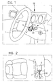
- Figure 1 is a perspective view of part of the passenger compartment of a motor vehicle, showing a lever control according to the invention, mounted near the steering wheel,
- Figure 2 is a view from above taken on the arrow II-II of Figure 1,
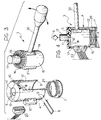
- Figure 3 is a partially exploded, perspective view of one embodiment of the lever control according to the invention, and
- Figure 4 is a partially axially sectioned side view of the control shown in Figure 3.
- In Figures 1 and 2, the steering wheel of a motor vehicle is indicated 1. A lever control according to the invention, generally indicated 3, is fixed on one side of the steering-
column housing 2. - As can best be seen in Figures 3 and 4, the
control 3 includes asupport casing 4 which, in the embodiment shown by way of example, is substantially cylindrical and hollow. The upper end of the casing has an integralannular wall 5 and its opposite end has an annular shoulder 6 against which a disc-shaped base 7 is disposed and is held in place, for example, by a metal wire hair-pin-like locking element 8, the ends of which are opened out in the mounted condition. The arms or sides of the element extend through corresponding pairs of holes in the side wall of thecasing 4 below the shoulder 6. One pair of holes, indicated 9, is visible in Figure 3. - Naturally, other systems may be used for closing the lower end of the
casing 4. - In the embodiment shown by way of example, the
casing 4 has twoexternal appendages 10 so that it can be fixed to the steering-column housing, for example, by screws or the like. Naturally, various other solutions may also be used for mounting thecasing 4 on the steering-column housing 2. - In Figures 3 and 4, the central hole in the
annular wall 5 at the end of thecasing 4 is indicated 11. The side wall of the casing has two longitudinal holes or slots, indicated 12 and 13. - As shown in Figure 4, a
body 15 is movable in thesupport casing 4. In the embodiment shown by way of example, the body is substantially cylindrical and has a ring ofradial teeth 16 on its top. Anappendage 17 which, in the embodiment shown by way of example, is cylindrical extends axially from the central region of the ring of teeth. - The internal surface of the annular
upper end wall 5 of thecasing 4 has a ring ofradial teeth 18 complementary to those of thebody 15. - The body is shorter than the distance between the base 7 and the
annular end wall 5 of thecasing 4 in the assembled condition. - As can be seen in Figure 4, in the assembled condition, the
body 15 is housed in thecasing 4 and its ring ofradial teeth 16 meshes with the corresponding ring ofradial teeth 18 of the casing. Ahelical spring 20 urges thebody 15 to the position shown in Figure 4 and retains it therein, theappendage 17 extending from thecasing 4 through thehole 11 in itsend wall 5. - Electrical switches for controlling the electrical supply to one or more electrical devices in the vehicle are housed in the
body 15 in known manner. The switches are operable as a result of the movement relative to thebody 15 of an associatedcontrol lever 30 which extends through ahole 19 in the body. - When the device is assembled, the
lever 30 extends through the hole orslot 12 in thecasing 4 and, together with thebody 15, can perform an angular movement relative to thecasing 4, the extent of the movement being determined by the angular extent of thehole 12. The movement takes place about the axis of thebody 15, indicated X-X in Figure 4. - In the embodiment shown by way of example, the side of the
body 15 opposite thelever 30 has aseat 21 for a terminal box which can be connected to anelectrical connector 22 for connection to the electrical device or devices of the vehicle which can be switched on and off by the operation of thelever 30. In the embodiment shown, the connector extends through the hole orslot 13 in thehousing 4. - In use, if the user wishes to change the distance between the
operating lever 30 in its rest position and the steering wheel 1, he presses theappendage 17 of thebody 15 so as to disengage the frontal rings ofteeth biasing spring 20. In this condition, theoperating lever 30 and the associatedbody 15 can be rotated together relative to thecasing 4 and moved to a different angular position relative thereto. When this position has been reached, theappendage 15 is released and the biasingspring 20 re-engages the rings offrontal teeth - In order to facilitate the meshing of the teeth, each tooth may conveniently be formed with one or more inclined surfaces.
- The operations indicated above thus enable the
control lever 30 to be positioned in a plurality of possible positions relative to the steering wheel 1, as indicated in Figure 2. - Naturally, the invention extends to all embodiments which achieve equal utility by means of the same innovative concepts.
- Thus, the surfaces of the
casing 4 and thebody 15 which have the frontal teeth may be replaced by other disconnectible retaining means of known type, or even by friction rings.
Claims (4)
- A lever control for controlling electrical equipment in a motor vehicle, including:- a body (15) which can be mounted near the steering wheel (1) and carries electrical switch means (30, 21, 22) which are operable, as a result of the movement of a control lever (30) which is movable relative to the body (15), to control the electrical supply to one or more electrical devices in the vehicle,
characterised in that it also includes:- a support casing (4) which can be fixed near the steering wheel (1) and defines a seat in which the body (15) is movable, the casing (4) having at least one hole (12) through which the lever (30) extends so as to be movable within a predetermined area, and- disconnectible retaining means (16, 18) for retaining the body (15) in a position selected from a plurality of possible positions relative to the casing (4), each position corresponding, in use, to a different position of the control lever (30) relative to the steering wheel (1). - A control device according to Claim 1, characterised in that the body (15) is rotatable in the casing (1) about an axis (X) and can move relative to the casing (1) along the axis (X).
- A control device according to Claim 2, characterised in that one end of the body (15) has a ring of radial teeth (16) coaxial with the axis (X) and the seat in the casing (4) has a complementary ring of teeth (18) facing the ring of teeth (16) on the body (15), and in that resilient means (20) urge the ring of teeth on the body (15) into frontal engagement with the ring of teeth in the casing (4).
- A control device according to Claim 3, characterised in that one end of the casing (4) has a further hole (11) coaxial with the axis (X), and in that the body (15) has an end appendage (17) which extends from the casing (4) through the further hole (11), and can be pressed manually, against the action of the resilient means (20), so as to disengage the rings of teeth (16, 18), enabling the body (15) and the lever (30) to be repositioned in a different angular position relative to the casing (4).
Applications Claiming Priority (2)
| Application Number | Priority Date | Filing Date | Title |
|---|---|---|---|
| IT000088 IT223247Z2 (en) | 1991-04-17 | 1991-04-17 | LEVER CONTROL DEVICE WITH ADJUSTABLE POSITION FOR E-ELECTRIC VEHICLE EQUIPMENT OF VEHICLES, INTENDED TO BE MOUNTED NEAR THE STEERING WHEEL. |
| ITTO910088 | 1991-04-17 |
Publications (1)
| Publication Number | Publication Date |
|---|---|
| EP0509969A1 true EP0509969A1 (en) | 1992-10-21 |
Family
ID=11408899
Family Applications (1)
| Application Number | Title | Priority Date | Filing Date |
|---|---|---|---|
| EP92830182A Ceased EP0509969A1 (en) | 1991-04-17 | 1992-04-14 | A lever control for electrical equipment in a motor vehicle |
Country Status (2)
| Country | Link |
|---|---|
| EP (1) | EP0509969A1 (en) |
| IT (1) | IT223247Z2 (en) |
Cited By (2)
| Publication number | Priority date | Publication date | Assignee | Title |
|---|---|---|---|---|
| US5823066A (en) * | 1996-05-13 | 1998-10-20 | Ethicon Endo-Surgery, Inc. | Articulation transmission mechanism for surgical instruments |
| EP1621954A1 (en) * | 2004-07-28 | 2006-02-01 | Marquardt GmbH | Electrical joystick controller |
Citations (4)
| Publication number | Priority date | Publication date | Assignee | Title |
|---|---|---|---|---|
| US2108745A (en) * | 1936-10-15 | 1938-02-15 | Dodd Victor John | Adjustable control lever |
| FR2114300A5 (en) * | 1970-11-13 | 1972-06-30 | Egretier M | |
| FR2458413A1 (en) * | 1979-06-11 | 1981-01-02 | Heuliez Sa Louis | Regulating mechanism for vehicle heating system - has positive retention mechanism to hold set position of regulating lever |
| WO1990006245A1 (en) * | 1988-12-02 | 1990-06-14 | Swf Auto-Electric Gmbh | Steering column switch for motor vehicles |
-
1991
- 1991-04-17 IT IT000088 patent/IT223247Z2/en active IP Right Grant
-
1992
- 1992-04-14 EP EP92830182A patent/EP0509969A1/en not_active Ceased
Patent Citations (4)
| Publication number | Priority date | Publication date | Assignee | Title |
|---|---|---|---|---|
| US2108745A (en) * | 1936-10-15 | 1938-02-15 | Dodd Victor John | Adjustable control lever |
| FR2114300A5 (en) * | 1970-11-13 | 1972-06-30 | Egretier M | |
| FR2458413A1 (en) * | 1979-06-11 | 1981-01-02 | Heuliez Sa Louis | Regulating mechanism for vehicle heating system - has positive retention mechanism to hold set position of regulating lever |
| WO1990006245A1 (en) * | 1988-12-02 | 1990-06-14 | Swf Auto-Electric Gmbh | Steering column switch for motor vehicles |
Cited By (2)
| Publication number | Priority date | Publication date | Assignee | Title |
|---|---|---|---|---|
| US5823066A (en) * | 1996-05-13 | 1998-10-20 | Ethicon Endo-Surgery, Inc. | Articulation transmission mechanism for surgical instruments |
| EP1621954A1 (en) * | 2004-07-28 | 2006-02-01 | Marquardt GmbH | Electrical joystick controller |
Also Published As
| Publication number | Publication date |
|---|---|
| IT223247Z2 (en) | 1995-06-21 |
| ITTO910088U1 (en) | 1992-10-17 |
| ITTO910088V0 (en) | 1991-04-17 |
Similar Documents
| Publication | Publication Date | Title |
|---|---|---|
| JP3566693B2 (en) | Steering wheel | |
| US5581058A (en) | Multifunction switch stalk for controlling vehicle functions | |
| US5936215A (en) | Steering roller connector signal transmission device on a steering wheel column | |
| US5491311A (en) | Multifunction switch | |
| CA1111539A (en) | Signal switch assembly | |
| CA1261375A (en) | Multiple function control stalk having linearly movable wiper delay rheostat | |
| JP2000512072A (en) | Switching device having secondary switching function | |
| EP1211119B1 (en) | Vehicle-mounting steering switch | |
| US20070235315A1 (en) | Handle switch device of vehicle | |
| GB2313710A (en) | Switch assembly | |
| US4383148A (en) | Steering wheel switch and electrical interconnection assembly | |
| US5939686A (en) | Electrical rotary push switch | |
| US5334023A (en) | Device for transferring a signal between two end points which are movable relative to each other | |
| JP3765550B2 (en) | In-vehicle knob switch device | |
| EP0749087A2 (en) | Electrical switch for use in an automotive vehicle | |
| EP1323580B1 (en) | Multiple switch module | |
| EP0509969A1 (en) | A lever control for electrical equipment in a motor vehicle | |
| EP0861753B1 (en) | Combination switch | |
| CA2011197A1 (en) | Tilt steering column latch release | |
| GB1562427A (en) | Electric slip coupling for a signalling device for use on steering wheels for motor vehicles | |
| US6150620A (en) | Steering column switch for a motor vehicle | |
| EP0886589B1 (en) | Column mounted switch assembly for a vehicle | |
| JP2518922B2 (en) | Steering column harness protector | |
| EP1076193A1 (en) | Operating apparatus with a rotary knob for use in an automatic transmission | |
| JP2002502105A (en) | Stick switches, especially turning stick switches for motorized vehicles |
Legal Events
| Date | Code | Title | Description |
|---|---|---|---|
| PUAI | Public reference made under article 153(3) epc to a published international application that has entered the european phase |
Free format text: ORIGINAL CODE: 0009012 |
|
| AK | Designated contracting states |
Kind code of ref document: A1 Designated state(s): DE ES FR GB SE |
|
| 17P | Request for examination filed |
Effective date: 19921031 |
|
| 17Q | First examination report despatched |
Effective date: 19940419 |
|
| STAA | Information on the status of an ep patent application or granted ep patent |
Free format text: STATUS: THE APPLICATION HAS BEEN REFUSED |
|
| 18R | Application refused |
Effective date: 19941009 |