EP0510781A2 - Method for adjusting two members of a forage harvester - Google Patents
Method for adjusting two members of a forage harvester Download PDFInfo
- Publication number
- EP0510781A2 EP0510781A2 EP92202290A EP92202290A EP0510781A2 EP 0510781 A2 EP0510781 A2 EP 0510781A2 EP 92202290 A EP92202290 A EP 92202290A EP 92202290 A EP92202290 A EP 92202290A EP 0510781 A2 EP0510781 A2 EP 0510781A2
- Authority
- EP
- European Patent Office
- Prior art keywords
- shear bar
- cutter head
- value
- program
- automatically
- Prior art date
- Legal status (The legal status is an assumption and is not a legal conclusion. Google has not performed a legal analysis and makes no representation as to the accuracy of the status listed.)
- Granted
Links
Images


Classifications
-
- A—HUMAN NECESSITIES
- A01—AGRICULTURE; FORESTRY; ANIMAL HUSBANDRY; HUNTING; TRAPPING; FISHING
- A01F—PROCESSING OF HARVESTED PRODUCE; HAY OR STRAW PRESSES; DEVICES FOR STORING AGRICULTURAL OR HORTICULTURAL PRODUCE
- A01F29/00—Cutting apparatus specially adapted for cutting hay, straw or the like
- A01F29/09—Details
-
- A—HUMAN NECESSITIES
- A01—AGRICULTURE; FORESTRY; ANIMAL HUSBANDRY; HUNTING; TRAPPING; FISHING
- A01D—HARVESTING; MOWING
- A01D34/00—Mowers; Mowing apparatus of harvesters
- A01D34/01—Mowers; Mowing apparatus of harvesters characterised by features relating to the type of cutting apparatus
- A01D34/412—Mowers; Mowing apparatus of harvesters characterised by features relating to the type of cutting apparatus having rotating cutters
- A01D34/42—Mowers; Mowing apparatus of harvesters characterised by features relating to the type of cutting apparatus having rotating cutters having cutters rotating about a horizontal axis, e.g. cutting-cylinders
- A01D34/62—Other details
-
- A—HUMAN NECESSITIES
- A01—AGRICULTURE; FORESTRY; ANIMAL HUSBANDRY; HUNTING; TRAPPING; FISHING
- A01F—PROCESSING OF HARVESTED PRODUCE; HAY OR STRAW PRESSES; DEVICES FOR STORING AGRICULTURAL OR HORTICULTURAL PRODUCE
- A01F29/00—Cutting apparatus specially adapted for cutting hay, straw or the like
- A01F29/09—Details
- A01F29/095—Mounting or adjusting of knives
-
- A—HUMAN NECESSITIES
- A01—AGRICULTURE; FORESTRY; ANIMAL HUSBANDRY; HUNTING; TRAPPING; FISHING
- A01D—HARVESTING; MOWING
- A01D2101/00—Lawn-mowers
Definitions
- the present invention relates to forage harvesters and more particularly to a method and apparatus for automatically adjusting the position of a member, such as a shear bar so that it is parallel to another member, such as a rotating cutter head.
- US-A-4,436,248 and co-pending U.S. Patent Application Serial No. 06/783,391 each disclose an apparatus for manually adjusting the shear bar in a forage harvester relative to a rotating cutter head carrying a plurality of knives.
- adjustment is accomplished by manually turning a first or a second knob, thereby to move a first or a second end of a shear bar.
- adjustment is carried out by turning the knobs and listening for the "tick" as the rotating cutter blades make contact with the shear bar. When the "tick" is heard, the shear bar is backed off until the sound is no longer heard. The adjustment is imprecise, time consuming, and requires that the operator leave his seat to accomplish the adjustment.
- DE-A-2926538 discloses a similar manual adjustment for a single shear bar.
- DE-A-33 45 749 discloses the use of a motor for simultaneously driving linkages connected to both ends of a harvester shear bar automatically to adjust the shear bar relative to a rotating cutter head. Because both linkages are driven by a single motor, and are thus driven equally, it is not possible automatically to adjust the shear bar if it is not initially parallel to the cutter head and parallelism must be effected manually before the automatic adjustment may be accomplished.
- DE-A-35 35 902 discloses a similar arrangement based on a single, bidirectional motor and also discloses the use of opto-electrical means for sensing the gap between the shear bar and cutter head, and also the use of microprocessor control means.
- German OS 30 10 416 discloses the use of an acoustic or optical non-contact sensor for monitoring the gap between the fixed and moving blades of a harvester.
- the sensor monitors the gap between the fixed and moving blades by sensing the proximity of the moving blades and if the gap varies beyond predetermined limits the harvester operation is stopped. No provision is made for utilising the sensor output to adjust the gap.
- the present invention is defined in the appended claims and provides a method of adjusting clearance between members of a forage harvester having a pair of members for processing material introduced therebetween, a first adjuster connected to a first end of one of the members, a second adjuster connected to a second end of the one member and a control unit cooperable with the adjusters for automatically adjusting the clearance between the members; the method being characterised in that it comprises the steps of : automatically moving the first end of the one member towards the other member until the first end engages the other member, then automatically moving the first end a first distance away from the other member; automatically moving the second end of the one member towards the other member until the second end engages the other member, then automatically moving the second end the first distance away from the other member; automatically moving the first end of the one member towards the other member until the first end re-engages the other member, then automatically moving the first end a second distance away from the other member; and automatically moving the second end of the one member towards the other member until the second end re-engages the other member,
- FIG. 1 schematically illustrates a cutting apparatus comprising a rotating cutter head 100 and an adjustable but fixed shear bar 102.
- the cutting apparatus may be the cutter head and shear bar of a forage harvester as illustrated in co-pending U.S. Patent Application Serial No. 784,391 (Patent No. 4,678,130).
- the shear bar 102 is mounted on a support bar 104 but is movable with respect to the support bar by actuation of linkages such as a pair of lead screws 106, 108.
- the cutter head 100 carries a plurality of knives which, as the cutter head rotates, cooperate with the shear bar 102 to cut material passing between the cutter head and the shear bar.
- a first bidirectional motor 110 drives lead screw 106 which is linked to a first end A of the shear bar.
- a second bidirectional motor 112 drives lead screw 108 which is linked to a second end B of the shear bar.
- Adjustment of the shear bar 102 relative to the cutter head 100 is accomplished with the cutter head rotating.
- a tachometer 114 senses rotation of the cutter head shaft and produces a sequence of pulses indicating the cutter head speed which is applied to an electrical control circuit 116. Adjustment is accomplished by sensing vibrations, or the absence of vibrations in the support bar 104 resulting from contact, or the lack of contact, between the shear bar 102 and the knives of the rotating cutter head.
- a vibration sensor 118 which may be a crystal, is attached to the support bar 104.
- the support bar has an internally threaded hole 120 ( Figure 3) for receiving a threaded mounting stud provided on the crystal mount.
- a solenoid-actuated knocker 122 is provided for determining the operability of the knock sensor.
- the knocker 122 has a threaded mounting stud which secures the knocker to an internally threaded hole 124 in the support bar 104.
- the solenoid has a spring-biased armature which carries an impact element 126 at its end. When the solenoid is energised it drives the impact element 126 into contact with the support bar 104, inducing vibrations in the support bar which are sensed by the sensor 118.
- the electrical control 116 pulses the knocker 122 and analyses the signals returned by the sensor 118.
- a push-button switch 128 is provided on a control panel near the operator. Each time the operator actuates switch 128, the electrical control circuit 116 checks the operability of sensor 118 as well as its sensitivity, checks to determine that the cutter head 100 is rotating and selectively energises first one of the motors 110, 112 and then the other until the cutter bar 102 is essentially parallel to the cutter head 100 and spaced therefrom by no more than a small predetermined distance on the order of a few thousandths of an inch.
- the electrical control circuits 116 are illustrated in Figures 4A and 4B and include a microprocessor 200, an EPROM 202, an analog-to-digital converter (ADC) 204, a peripheral interface adapter (PIA) 206, a versatile interface adapter (VIA) 208, an address decoder or selector 210 and a watch dog circuit 212. All units except the watch dog circuit are interconnected by an 8-bit bidirectional data bus 214 and/or a 16-bit address bus 216.
- ADC analog-to-digital converter
- PDA peripheral interface adapter
- VIP versatile interface adapter
- All units except the watch dog circuit are interconnected by an 8-bit bidirectional data bus 214 and/or a 16-bit address bus 216.
- VIA 208 Since the details of the VIA 208, microprocessor 200, EPROM 202, ADC 204, PIA 206, and address decoder 210 are well known in the art, they are not described in detail herein but a brief description of each is given below.
- the microprocessor 200 may be a Motorola type 6802 microprocessor including an internal memory for limited storage of data during a processing operation.
- the microprocessor has eight input/output terminals D7-D0 which are connected to the data bus 214 and sixteen output terminals A15-A0 for supplying an address generated within the microprocessor to the address bus 216.
- D7-D0 input/output terminals
- A15-A0 sixteen output terminals
- VMA Valid Memory Address
- Microprocessor 200 has a non-maskable interrupt (NMI) input terminal. A low-going signal at this terminal causes the microprocessor 200 to initiate a non-maskable interrupt sequence.
- the microprocessor 200 also has a reset input terminal R ⁇ and when the signal on lead 230 goes to low the registers within the microprocessors are cleared and the microprocessor becomes inactive. When the signal at terminal R ⁇ goes high it causes the microprocessor 200 to begin a restart sequence.
- NMI non-maskable interrupt
- Address bus bits A15-A13 are connected to input terminals of the address decoder 210. Each time the microprocessor outputs a signal on lead 220, it enables the address decoder to decode the three address bits and produce a signal on one of the leads 223-226.
- the lead 223 is connected to the CS2 ⁇ input of VIA 208.
- Lead 224 is connected to the OE ⁇ and CE ⁇ inputs of EPROM 202.
- Lead 225 is connected to the CS ⁇ input of ADC 204 while lead 226 is connected to the CS2 ⁇ input of PIA 206.
- the EPROM 202 may be a type 2764 capable of storing 8K 8-bit bytes. When the signal on lead 224 is low the location in the EPROM specified by the address applied to the EPROM from bus 216 is accessed. The location is either written to from the microprocessor, or read out to the microprocessor, depending upon whether the signal R/ W ⁇ is low or high, respectively. EPROM 202 stores data and the program which is executed by the microprocessor.
- the VIA 208 may be a type 6522 such as that manufactured by Rockwell or Synertek. As disclosed at page 2526-2530 of the publication IC Master 1980, published by United Technical Publications, the VIA 208 includes 16 addressable registers and interval timers or counters. These registers and interval timers are addressed by applying an address from the four low order of bits of the address bus 216 to the register select input RS3-RS0. Data is read from, or entered into the registers and counters through data terminals D7-D0 which are connected to the data bus 214.
- the VIA is enabled only when the microprocessor outputs a hexadecimal address, the high order bits of which cause the address decoder 210 to produce a low signal on lead 223 which enables the chip select ( CS2 ⁇ ) input of the VIA.
- the register or counter which is accessed is determined by the four low order bits of the address bus which are applied to register select inputs RS3-RS0 of the VIA.
- the accessed register or counter is either read from or written into depending upon whether the microprocessor 200 outputs a high or low level signal, respectively, on lead 218 to R/ W ⁇ terminal of the VIA.
- the 02 input of the VIA is a clocking input and is used to trigger data transfers.
- VIA 208 It is connected by lead 222 to the E terminal of the microprocessor 200. All circuits within VIA 208 are reset when the signal RES ⁇ on lead 230 goes low. The VIA 208 produces an output signal CB2 which is used for control purposes.
- the microprocessor program periodically sends a byte of control information to VIA 208 to toggle CB2 and pulse watch dog circuit 212.
- the watch dog circuit may be two monostable multivibrators connected in series. Periodic pulses produced on lead 232 by the VIA periodically reset the watch dog circuit so that its output remains inactive. If the program should fail to send signals to the VIA 208 so that lead 232 is pulsed, the watch dog circuit times out and emits an output signal to reset the microprocessor, the VIA and the PIA 206.
- the watch dog circuit 212 also has an input 234 which is derived from a monitoring circuit (not shown) which monitors the logic circuit supply voltage. If this voltage should vary outside predetermined limits the signal on lead 234 cause the watch dog circuit 212 to produce an output signal to reset the microprocessor, the PIA and the VIA.
- the 5V supply voltage for the circuits of Figures 4A and 4B may be derived from the 12V battery which supplies power for the harvester if it is self-propelled, or from the battery for the tractor which pulls the harvester.
- VIA 208 has two 8-bit input/output ports PA and PB. The bit positions of the ports are individually programmable as either an input or an output.
- Two buses, collectively designated 231, connect PA and PB to external circuits shown in Figure 4B.
- the port A bus is connected to receive the outputs of a plurality of amplifiers 241-244.
- Amplifier 241 has one input connected to the 5V logic supply voltage and a second input connected through two resistors 248 and 250 to the 12V power supply.
- the junction between resistors 248 and 250 is connected through a switch 252 to ground. As long as switch 252 is closed the amplifier applies a logic 0 signal to the bus but when switch 252 is open the amplifier applies a logic 1 signal to the bus.
- the switch 252 is associated with an engage lever (not shown) which is actuated so that a chain drive causes the cutter head 100 to rotate. Switch 252 is thus closed when drive power is applied to the cutter head.
- Amplifiers 242-244 are arranged in the same manner as amplifier 241, with switches 254 and 256 being associated with amplifiers 242 and 243, respectively, and switches 258 and 260 being associated with amplifier 244. These switches are all limit switches for sensing when the ends of the shear bar 102 have reached their limits of travel toward or away from the cutter head 100. Switches 254 and 256 are actuated when ends A and B, respectively, of the shear bar 102 are at their limit of travel away from the cutter head 100. Switches 258 and 260 are connected in series so that amplifier 244 produces a logic 1 output when either switch is opened, i.e. when either end A or end B is at its limit of travel toward the cutter head 100.
- the limit switches 258, 260 are incorporated within the housings of motors 110 and 112 and are actuated by mechanical bidirectional counter mechanisms which count rotations of lead screws 106 and 108.
- the tachometer 114 ( Figure 1) produces a sequence of output pulses at a rate proportional to the speed of rotation of the cutter head 100.
- the pulses are applied over a lead 262 ( Figure 4B) to one input of a comparator amplifier 264.
- a voltage divider comprising two resistors 266 and 268 is connected between 5V and ground, and a reference voltage is applied from the junction of the resistors to a second input of amplifier 264.
- amplifier 264 applies a logic 1 signal to bit position 6 of the B bus. These pulses are counted by a counter (timer 2) in VIA 208.
- Five bits of port B of the VIA are connected by a B bus to five inverters 270-274.
- the outputs of inverters 270-273 are connected to the bases of grounded emitter transistors 280-284, respectively.
- the collectors of transistors 280-283 are connected to the 12V source through the coils of relays K2-K5, respectively, while the collector of transistor 285 is connected to the 12V source through an audible alarm 286.
- the direction of rotation of motor 110 is controlled by the contacts of relays K2 and K3, only one of which may be energised at any given time. If relay K2 is energised the motor rotates in one direction to move end A ( Figure 2) of the shear bar 102 inwardly toward the cutter head 100.
- the current flow path extends from 12V through contacts K2a, motor 110, normally closed contacts K3b and resistor 288 to ground.
- relay K3 is energised, a circuit extends from the 12V source through contacts K3a, motor 110, contacts K2b and resistor 288 to ground.
- motor 110 Since current flow is in the opposite direction through the motor, it rotates in the opposite direction to move end A of the shear bar 102 away from the cutter head 100. If neither relay K2 or K3 is energised, motor 110 does not rotate because contacts K2a and K3a are both open.
- Relays K4 and K5 have normally open contacts K4a and K5a and normally closed contacts K4b and K5b. Relays K4 and K5 control the motor 112 in exactly the same manner that motor 110 is controlled by relays K2 and K3.
- Bit 7 of port B of VIA 208 is controlled by one of the timers in VIA 208.
- the timer (TIC) causes an interrupt pulse to appear at PB7 each time the counter is loaded, the delay between the loading of the counter and the occurrence of the pulses being determined by the value entered into the counter.
- PB7 is connected by a lead 235 to the NMI ⁇ input of microprocessor 200 so that the program being executed by the microprocessor is interrupted periodically and a routine is executed to read the various switches and output various control signals to the VIA and PIA buses.
- One bit of the PB bus is connected to a type 3548 PNP drive circuit.
- the output of the driver circuit is connected to ground through the solenoid of knocker 122.
- the solenoid is energised to induce vibrations in the shear bar 104 and the resulting vibrations sensed by sensor 118 are analysed to determine its operability.
- the PIA 206 may be a type 6821 peripheral interface adapter. This device is well known in the art and is generally similar to VIA 208 except that it does not include timers.
- PIA 206 has two 8-bit ports PA and PB connected to an A bus and a B bus, collectively illustrated as buses 300. The bit positions of the ports are individually programmable for input or output. Only 2-bit positions of port A are utilised and they are programmed as inputs. These bit positions receive the outputs of the two amplifiers 302 and 304.
- a quit switch 306 is connected between ground and one input of amplifier 302 so that when the switch is closed the amplifier applies a logic 1 signal to the PIA over the bus. Switch 306 is actuated to halt or interrupt a shear bar adjusting operation.
- the switch 128 is connected to one input of amplifier 304 and when this switch is actuated the amplifier applies a logic 1 signal to the PIA over the bus.
- Switch 128 is the ADJUST switch which initiates a shear bar adjusting sequence.
- PIA 206 Only seven bits of port B of PIA 206 are utilised and they are all programmed as outputs. Each bit is connected through a driver 310 and an LED 314 to 12V.
- the LEDs provide an operator with visual alarms or indications of the status of the system by indicating that the system is ready to begin an adjusting cycle; switch 306 has been actuated to interrupt an adjusting cycle; a motor 110 or 112 has stalled; the cutter head is not rotating; an end of travel has been reached; the sensor 118 is bad; or a shear bar adjusting operation is in progress.
- ADC 204 may be a type 0844 converter such as that described at page 3537 of the publication IC Master, Vol. 2, 1984.
- the converter has four multiplexed input channels but only CH1, CH2 and CH4 are utilised in the present invention.
- the converter is enabled only when the address applied to selector 210 by microprocessor 200 causes the signal on lead 225 to be low. This lead is connected to the CS terminal of the converter.
- the microprocessor 200 starts a converter cycle by placing a command on data bus 214 to select the channel, and driving lead 218 low.
- Lead 218 is connected to one input of two NANDs 320 and 322.
- the second input of NAND 320 is connected to +5V and the output of the NAND is connected to a further NAND 324.
- the E output of microprocessor 200 is connected to one input of NANDs 322 and 324 and the outputs of these NANDs are connected to the R ⁇ and WR ⁇ inputs, respectively, of the converter.
- NAND 324 produces a low output when the clocking signal on lead 222 goes high.
- the output of NAND 324 enables the converter so that the operation specified by the command is carried out.
- microprocessor 200 It takes the converter about 40 microseconds to convert an analog value to a digital value.
- the programming of microprocessor 200 is such that once it initiates a cycle of converter 204 it either waits or performs other operations until at least 40 microseconds have elapsed.
- the microprocessor 200 then places an address on bus 216 so that selector 210 produces a signal on lead 225 to select the converter.
- the microprocessor 200 drives the signal on lead 218 high.
- NAND 322 produces an output signal which enables the converter to place the converted value on bus 214 from whence it passes to the microprocessor 200.
- the analog signal from knock sensor 118 is applied to the CH1 input of the A/D converter through a circuit ( Figure 5) including resistors 328 and 329, amplifiers 330 and 332, a peak hold circuit 334 and a buffer amplifier 336.
- a pair of resistors 331, 333 provide a first reference voltage which is added to the knock sensor output signal, the output of amplifier 330 being proportional to the sum of the reference signal and the differential signal derived from the sensor.
- a second reference voltage is derived from a voltage divider comprising resistors 337 and 339. The second reference voltage is applied to an amplifier 340 and the output of the amplifier is tied to a junction 338 between the peak hold circuit 334 and buffer amplifier 336.
- the output of amplifier 341 is also applied to the CH4 input of ADC 204.
- the ADC 204 is controlled to operate in a differential mode so that it determines the difference in the magnitude of the analog signals at CH1 and CH4 and converts this difference to a digital value for transmission to the microprocessor 200.
- Resistors 343 and 345 form a voltage divider which is tapped to provide an input to an amplifier 346. The output of this amplifier is applied to the V r input of ADC 204 to set the range of the converter.
- motors 110 and 112 control the movement of the shear bar 102.
- the circuit for energising either motor 110, 112 in either direction extends through current sensing resistor 288.
- the voltage developed across resistor 288 is applied through an operational amplifier 340, filter circuit 342, and buffer amplifier 344 to the CH2 input of ADC 204 where it may be sampled.
- the ADC does not subtract the magnitude of the CH4 signal from the CH2 before doing an ADC.
- the microprocessor 200 When power is turned on the microprocessor 200 automatically goes through an initialisation routine ( Figure 6) during which the various registers and timers in the VIA and PIA are set up. This routine also clears the switch registers or locations in memory 202 which store indications of the last sampled state of the various switches. The routine then clears the QUIT, PULSW, and RPMOK flags and sets a FIRST flag. In addition, flags are set to turn off the alarm and alarm lights as well as the sensor light. The stack in the microprocessor 200 is initialised after which the program proceeds to the first step of the READY routine.
- the READY routine is illustrated in Figure 7. It begins at step 700 by setting the flag POUTF.
- the ready light flag is set so that the ready light may be turned on when the NMIR routine is next executed.
- the sensor light flag is cleared so that the sensor light will be turned off the next time VIA 208 pulses the watchdog circuit 212.
- the BUSY and ALFLG flags are cleared after which the program proceeds to step 702 where it executes a wait for interrupt instruction.
- a pulse occurs at PB7 of the VIA 208 thereby pulsing the NMI ⁇ input to microprocessor 200.
- the microprocessor interrupts the routine it is executing, in this case the READY routine, and executes the NMIR routine illustrated in Figure 8.
- the NMIR routine loads the counter TIC in VIA 208. This counter is decremented and when it reaches zero it will again pulse PB7 of the VIA to initiate another NMIR routine.
- the VIA next senses the QUIT and ADJUST switches and sets flags indicating which switches are actuated. In addition, if both switches are actuated a flag PULSW is set.
- the microprocessor then addresses the ADC 204 to initiate a read-convert cycle with CH2 as the selected input. This samples the motor current and converts it to a digital value.
- step 801 the CLFLG flag is tested to see if the clutch in the cutter head drive chain has been engaged to actuate clutch switch 252. If it has not, a flag is set to turn on one of the indicator lights 314 to indicate that the RPM of the cutter head is not within limits, and the program branches to step 812 to turn on the indicator. A return is then made to the routine which was interrupted.
- step 802 the FIRST flag is tested. This flag was set during the INIT routine so the program proceeds from step 802 to step 804 where FIRST is cleared and a value is set into RPMFLG. This value will be counted down to time the interval during which tachometer pulses produced by the cutter head tachometer 114 will be counted by timer 2 in VIA 208.
- RPMLFG is tested to see if the timing interval has elapsed. Assuming it has not, the program decrements RPMFLG at step 808 and at step 810 the converted value of the current flowing through the shear bar adjusting motors is read from ADC 204 and saved. At step 812 the program sends data to PIA 206 to turn on the appropriate indicator lights. The program then returns to the routine which is interrupted to execute the instruction following the last instruction executed before the interrupt.
- steps 702 and 704 comprise a loop which is repeatedly executed until the test at step 704 indicates that a preset interval of time has elapsed.
- the program then tests the ADJSW flag at 706 and the PULSW flag at step 708. Assuming that the ADJUST switch is not actuated either alone or concurrently with the QUIT switch, the program executes another Wait For Interrupt at step 710 and then loops back to step 700. Thus, assuming the ADJUST switch is not actuated the READY routine is repeatedly executed, the routine being interrupted every 2.5MS to execute the NMIR routine.
- step 804 Because FIRST is cleared at step 804 during the first execution of the NMIR routine after the cutter head clutch is engaged, the program branches from step 802 to 806 on the second and subsequent executions of the routine.
- RMPFLG is decremented at step 808 each time the NMIR routine is executed and after 255ms RPMFLG is reduced to zero.
- the test at step 806 proves true and the program moves to step 814 where the count of tachometer pulses accumulated by timer 2 in VIA 208 is read and saved, and RPMFLG is reloaded to time another 255ms interval.
- RPMMIN is a value representing the minimum permissible rate of rotation of the cutter head 100.
- RPMMIN is compared with count of tachometer pulses. If the count is equal to or greater than RPMMIN the RPMOK flag is set at step 818. If the count is less then RPMMIN then RPMOK is cleared at step 820. After step 818 or 820 the ADC 204 is addressed to again get the converted value of the adjusting motor current.
- the TSTGEN subroutine to check the operability of the knock sensor 118 and its associated circuitry.
- the TSTGEN subroutine is illustrated in Fig. 9 and begins at step 900 where TSTS is set to 3, SAMPLE is set to 64, and OKTST is cleared.
- a value is sent to VIA which causes the VIA to output a signal over its B bus to energise driver 275 thereby energising the knocker solenoid 122.
- the clapper 126 is driven against support bar 104. This induces vibrations in the support bar which may be sensed by knock sensor 118 to produce an analog signal.
- This signal passes through the circuit of Fig. 5 and is applied to the CH1 input of ADC 204.
- the microprocessor addresses the ADC and starts a conversion cycle.
- the microprocessor executes a delay loop waiting for 40 microseconds while the ADC samples the CH1 and CH4 inputs and converts the difference into a digital value.
- the microprocessor addresses the ADC and saves the digital value which is an indication of the output of the knock sensor.
- the program then enters a loop comprising steps 905-910.
- step 905 another analog-to-digital conversion cycle is started, at step 906 the microprocessor waits for completion of the conversion cycle, and at step 907 the converted value is retrieved from the ADC.
- Step 908 compares the latest (next) sample value with the previously converted value saved and the larger of the two values is saved.
- the value of SAMPLES is decremented and tested at step 910 and if it is not decremented to zero the program loops back to step 905.
- the knocker solenoid is pulsed once at step 901 to induce vibration into the shear bar support and the output of the knock sensor is sampled 64 times, the largest of the 64 samples being saved at step 909. After the 64th sample the test at step 910 proves true and the program proceeds to step 911 where the saved largest sample is compared with a value representing the minimum acceptable magnitude for the signal output of the knock sensor.
- step 912 If the largest sample is greater than or equal to the minimum acceptable magnitude OKTST is incremented at step 912 before TSTS is decremented at step 913. If the largest sample is less than the minimum acceptable magnitude the program branches from step 911 to step 913 without incrementing OKTST.
- TSTS is sampled to see if it has been decremented to zero. If it has not, the program branches back to step 901 to again pulse the knocker and determine the largest of the next 64 samples taken of the output of the knock sensor.
- step 914 After three tests have been completed the test at step 914 proves true and at step 915 OKTST is sampled to see if it is still zero. If it is not, it means that the knock sensor test was successful and found at least one sample larger than the required minimum value. If OKTST is still zero it means that the knock sensor is not sensitive enough to be used, or its output circuitry is not functioning properly.
- the program branches to step 916 to set flags to turn on an indicator 314 and the alarm 286. A jump is then made to an alarm routine to sound the alarm and turn off the motors.
- the ALARM routine is not illustrated, it may be noted that the program continuously executes a loop in the ALARM routine until the operator turns the power off and then on so that the program again executes the INITIALISE routine illustrated in Fig. 6.
- the subroutine GETNOI is illustrated in Figs. 10A and 10B. During execution of this routine the output of the knock sensor is tested up to four times, each test comprising 4096 samples. The maximum number of tests is set at step 1000 and the number of samples is set at step 1009.
- the purpose of GETNOI is to determine the noise vibrations induced in the shear bar as a result of normal machine operation, or more specifically the output of the knock sensor in response to these vibrations.
- the subroutine develops a digital indication of the noise and this digital indication is subsequently used in the ADJUST routine described below to set the sensitivity of the system to the output signal from the knock sensor.
- step 1001 the RPMOK flag is tested. This flag is set at step 818 of the NMIR routine if the cutter head speed is equal to or greater than the minimum speed represented by RPMMIN. If the cutter head is not up to speed the program branches to step 1002 where a flag is set to turn on the alarm. At step 1003 the program executes a Wait For Interrupt and after NMIR is executed to again sample the speed of the cutter head the program branches back to step 1001. The loop 1001-1003 is repeated until the speed of the cutter head is above the preselected minimum speed RPMIN. When the speed is satisfactory the NMIR routine will set RMPOK and upon return to GETNOI the test at step 1001 will prove true.
- step 1005 The program then turns off the alarm flag at step 1004 and at step 1005 jumps to the PULOUT subroutine, subsequently described, which controls the shear bar 102 adjusting motors 110 and 112 to move the shear bar away from the cutter head 100. This insures that there will be no contact between the cutter head and shear bar while the noise test is being made. Since the PULOUT routine energises only one motor each time it is executed, step 1005 actually represents two executions of the subroutine.
- step 1006 the program jumps to the TSTGEN subroutine to test the operability of the knock sensor and its output circuitry.
- steps 1007 and 1008 the program waits for an interrupt and for any vibrations induced in the shear bar during TSTGEN to die out.
- Step 1009 clears two locations designated HIGH and RAVG, and sets SAMPLES to 4096.
- the program then enters a loop comprising steps 1010-1014.
- the program jumps to a RDSENS subroutine.
- This subroutine is not illustrated but comprises steps equivalent to steps 902-904. That is, it starts a conversion cycle to sense and convert the output of the knock sensor (minus the input to CH4) to a digital value, waits until the conversion is completed, and reads the converted sensed value from the ADC.
- this sensed value is compared with HIGH and the larger value is saved at HIGH.
- Step 1012 adds the sensed value to RAVG which is an accumulated sum of all sensed values.
- SAMPLES is decremented and at step 1014 it is tested to see if 4096 samples have been taken. If not, the program loops back to step 1010.
- the program saves the largest of the samples at DATA2.
- the value in RAVG is tested by dividing it by a fixed value and testing the quotient to see if it exceeds a limit. If it does, it is an indication that there is too much background noise so the program branches to step 1022.
- a noise test will also fail if the highest noise value sensed exceeds the average noise value of all the samples by more than a fixed value NMRG.
- RAVG is added to NMRG and saved at DATA3.
- HIGH is then compared to the resulting sum at step 1020 and if HIGH is greater the program branches to step 1022.
- CYCLES is decremented at step 1022 and tested at step 1023. If it has been decremented to zero the program sets the alarm flag at step 1024 and jumps to the alarm routine. If four tests have not been completed the program branches from step 1023 back to step 1001.
- step 1020 If any test proves successful, then no further tests are made. If a test is successful then the test at step 1020 will prove false and the program proceeds to step 1021 where HIGH is added to MARG to obtain a "noise value".
- the ADJUST routine described below assumes that any output signal from the knock sensor less than this value is due to noise alone. the noise value is saved at NOI2, the POUTF flag is cleared, and a return is made to the calling routine.
- the PULOUT subroutine shown in Fig. 11 is called for the purpose of moving one end of the shear bar 102 out, i.e. away, from the cutter head 100 by a given amount.
- the microprocessor A register holds an indication of which motor 110 or 112 is to be energised and in what direction, and the X register holds a value CYCLES indicating how many 1/4-second intervals the motor is to be energised.
- the subroutine begins at step 1100 by checking POUTF. If the flag is set the program branches to step 1102 where QSEC is loaded with a value indicating 1/4-second. QSEC is decremented at step 1113 each time the loop comprising steps 1105-1116 is executed, and reaches zero after 1/4 second.
- the microprocessor sends the motor indication to the output register of VIA 208 controlling port B.
- a signal is produced on the B bus to energise one of the relays K3 or K5 so that one of the motors 110 or 112 is energised to begin moving one end of the shear bar 102 away from the cutter head 100.
- two counter locations HCNTR and LCNTR are loaded with values for timing high current and low current intervals.
- the motor current is checked as subsequently described to see if it exceeds a predetermined maximum value (e.g. the motor is stalled) or is less than a predetermined minimum value, (e.g. motor winding circuit is open). If it exceeds the maximum value for an interval of time corresponding to the count set in HCNTR or is less than the minimum value for an interval of time corresponding to the count set in LCNTR, the subroutine is terminated and an alarm condition indicated.
- a predetermined maximum value e.g. the motor is stalled
- a predetermined minimum value e.g. motor winding circuit is open
- the program executes a loop waiting for the motor circuit transients to die out.
- Each interrupt occurring during execution of the loop causes the NMIR routine to be executed and during its execution the motor current is sensed, converted to a digital value and saved, as explained with reference to Fig. 8.
- the saved current value is compared with a reference value to see if the current is too high. Assuming the motor current is not too high, HCNTR is reloaded at step 1108 to restart the high current timing interval.
- step 1109 the current value is compared to a minimum reference value to see if it is too low. Assuming it is not, LCNTR is reloaded at step 1110 to restart the low current timing interval. Steps 1111 and 1112 merely waste time so that the loop comprising steps 1105-1114 takes .01 second. At step 1113 QSEC is decremented and at step 1114 it is tested to see if it has reached zero. Assuming it has not, the program branches back to step 1105 and repeats the loop.
- step 1114 After 1/4 second the test at step 1114 proves true so the program moves to step 1115 where QSEC is reloaded to time another 1/4 second interval, and CYCLES is decremented. CYCLES is then tested at step 1116 to see if the required number of 1/4 second intervals have elapsed. If not, the program branches back to step 1105. If the required number of 1/4 second intervals has elapsed then the required movement of the motor is complete. At step 1117 the microprocessor sends a value to the output register of VIA 208 which turns off any motor that is on. A return is then made to the calling routine.V
- step 1100 If the test at step 1100 shows that POUTF is not set then the program tests the EOTOUT flag to see if either of the limit switches 254 or 256 is actuated. If either limit switch is actuated the program branches to step 1117, turns the motor off, and returns to the calling routine.
- step 1107 If the test at step 1107 shows that the motor current is too high, the program branches to step 1120 where HCNTR is decremented. HCNTR is then tested at 1121 to see if the high current condition has existed for too long a time. If it has not, the program moves to step 1111 and proceeds as described above. If the high current condition persists for too long a time, HCNTR will be decremented to zero and the test at step 1121 will prove true. In this case flags are set to turn on a stall indicator 314 and sound the alarm 286, after which the program jumps to the alarm routine.
- Steps 1130-1132 serve the same purpose as steps 1120-1122 except that they time the interval the motor current is below the required minimum.
- the ADJUST routine controls the motors M1 and M2 to adjust the shear bar relative to the cutter head.
- the program jumps to the ADJUST routine from step 706 of the READY routine if the adjust switch 308 has been actuated.
- the ADJUST routine begins at step 1200 where the BUSY flag is set and the READY LIGHT flag is reset so that indicators 314 will properly indicate the status of the system.
- EOTIN is tested to see if one of the switches 258 or 260 is actuated because one end of the shear bar 102 is at its limit of travel toward the cutter head 100. If neither switch is actuated step 1202 checks the RPMOK flag to be sure that the cutter head is rotating faster than a predetermined minimum speed. Assuming that the rpm is satisfactory the program clears the flag for setting the RPM indicator 314.
- the program jumps at step 1204 to the TSTGEN subroutine to test the knock sensor 118 and its output circuitry as previously described. Upon the return from this subroutine the program jumps to the GETNOI subroutine to determine the background noise.
- the microprocessor fetches M1IN and sets WICHMO to indicate that motor M1 is active.
- the program then obtains ONTIME, the number of 1/4 second intervals the motor M1 is to be energised.
- M1IN is then sent to VIA 208 and the VIA produces an output signal over its bus to energise relay K2 thereby energising motor M1 in a direction which moves end A (Fig. 2) of the shear bar 102 toward the cutter head 100.
- Step 1208 sets QSEC to time 1/4 second.
- Steps 1209 and 1210 introduce a 100MS delay to allow electrical transients resulting from the motor energisation to die down after which a jump is made to the RDSENS subroutine to sample the output of the knock sensor and convert it to a digital value.
- this value is compared with the value of NOI2 obtained during execution of GETNOI at step 1205. If the knock sensor output value is greater than NOI2 it indicates that the cutter head is hitting the shear bar so that program branches to Fig. 12C.
- step 1212 the program proceeds from step 1212 to step 1213 where the motor current value obtained during the last execution of the NMIR routine is compared to a value representing the maximum allowable current. If the motor current does not exceed the maximum allowable value then at step 1215 it is compared with a value representing the minimum allowable current. It may be noted that steps 1213-1222 of the ADJUST routine correspond exactly with steps 1107-1113, 1120-1122 and 1130-1132 of the PULOUT subroutine described above.
- step 1224 the EOTIN flag is checked to see if the motor has driven the end of the shear bar to its inward limit of travel. If it has not, the RPMOK flag is checked to see if the cutter head is still rotating. Assuming it is, QSEC is decremented at 1226 and then tested at 1227 to see if 1/4 second has elapsed.
- step 1227 If the test at step 1227 shows that 1/4 second has not elapsed then the program loops back to step 1211 and repeats the loop comprising steps 1211-1216 and 1224-1227. When 1/4 second has elapsed the test at step 1227 proves true and the program moves to step 1228 where it resets QSEC to time another quarter-second interval and decrements ONTIME, the number of quarter second intervals that the motor is to be on. In a typical system ONTIME may be about 10 such intervals.
- step 1229 After ONTIME is decremented it is tested at step 1229 to see if the motor energising interval has expired. If it has not, the program loops back to step 1211. If the energising interval has expired the program moves to step 1262 ( Figure 12C) where the flags IMP1, IMP2 and HITFLAG are cleared. The program then proceeds to step 1230 ( Figure 12D) where the microprocessor sends a code to VIA 208 which terminates the output signal for energising relay K2. When relay K2 opens motor M1 stops. A jump is then made to the TSTGEN subroutine to check the operation of the knock sensor before beginning the movement of the other motor.
- step 1233 it is set to indicate M2 and the code is obtained for controlling M2 to move the shear bar inwardly toward the cutter head.
- step 1234 it is set to indicate M1 and a code is obtained for controlling M1 to move the shear inwardly.
- M1 and M2 may be alternately energised one or more times as described above without driving either end of the shear bar into contact with the rotating cutter bar. Eventually however energisation of one of the motors will result in contact.
- RDSENS is executed at step 1211 to read the knock sensor output, this output will be larger than NOI2. Therefore, when the knock sensor output is compared to NOI2 at step 1212 the program recognises the hit and branches to step 1240 (Fig. 12C) where a code is sent to VIA 208 which deenergises all relays K2-K5 thereby stopping all motors.
- WICHMO is checked to see which motor caused the hit.
- IMP1 is set at step 1242.
- IMP1 and IMP2 are checked at step 1243 to see if both have been set. If both IMP1 and IMP2 are set then HITFLG is set at 1244 before step 1245 is executed. If IMP1 and IMP2 are not both set then the program branches from step 1243 to 1245.
- step 1245 the flag POUTF is cleared, the code for moving M1 outwardly is fetched to the microprocessor A register and BOUT, the number of quarter-second intervals the motor is to be energised, is loaded into the microprocessor X register. BOUT may be on the order of 5 such intervals. A jump is then made to the PULOUT subroutine to energise M1 in a direction to move the shear bar 102 away from the cutter head 100.
- HITFLG Upon return from the PULOUT subroutine HITFLG is tested. If it is not set, i.e. there has not been at least one impact by each of the motors, the program moves to step 1248 where the TSTGEN subroutine is executed to test the knock sensor. At step 1249 WICHMO is set to indicate M2, QSEC is reset to time a quarter-second interval, and the code is obtained for controlling the motor M2 to move the shear bar inwardly. The program then branches back to step 1207 where the motor is turned on by sending the code to the VIA 208.
- Step 1252-1259 correspond to steps 1242-1249 the only differences being that the flag IMP2 is set at step 1252, the code for energising M2 is obtained at step 1255, and WICHMO is set to M1 and the code for energising M1 is obtained at step 1259.
- a test at step 1247 or 1257 shows that HITFLG is set, the program then decrements TIMS at 1260 and tests it at 1261. If TIMS is not zero the program branches to 1262 to clear IMP1, IMP2 and HITFLG in preparation for checking for another set of impacts, one by each end of the shear bar. It then proceeds to Fig. 12D where the state of WICHMO is changed and the code for next energising one of the motors is obtained before branching back to step 1270 to energise the motor.
- step 1261 If the test at step 1261 proves true it means that the adjusting sequence is complete. A flag is set at step 1263 to beep the alarm 286, and the program then jumps to the READY routine.
- the shear bar is spaced on the order of .005 (0.127mm) to 0.010 inch (0.254mm) from the cutter head and essentially parallel thereto.
- the gap between the shear bar 102 and the cutter head 100 at the end of the adjusting procedure is governed in large part by the value of BOUT at step 1245 or 1255 which in turn controls the duration of motor energisation during the PULOUT subroutines at steps 1247 and 1248.
- the program sets flags to turn on one of the indicators 314 to indicate EOT and sound an alarm, and then jumps to the ALARM routine.
- the programs sets appropriate flags to turn on the RPM indicator and the alarm, and jumps to the ALARM routine.
- the RPMOK flag is tested prior to any motor actuation. If the flag is not set the program sets flags for giving the alarm indication at step 1281 tests the QUIT flag to see if the operator has depressed the Quit switch. If he has, the program jumps to the Ready routine. If he has not, a Wait for Interrupt is executed during the wait. The program then branches back to step 1202 to again check the RPMOK flag. If the cutter head is up to speed the program then clears the alarm flags at step 1203.
- the PULSW flag is set if the Quit and Adjust switches are actuated concurrently. By actuating both switches the operator may initiate the PULFOUT routine which moves each end of the shear bar 102 to its limit of travel away from the cutter head 100.
- step 708 shows that PULSW is set the program jumps to the PULFOUT routine shown in Fig. 13.
- step 1300 the Busy and POUTF flags are set, the length of time for energising the motor is loaded in the microprocessor X register, and the code for energising M1 to move the shear bar outwardly is entered in the A register.
- the program then jumps to the PULOUT subroutine to energise M1.
- PULFOUT EOTOUT1 is tested to see if end A of the shear bar is at its limit of travel. If not, the QUIT flag is tested at 1303.
- Step 1304 the microprocessor gets the control values for moving motor M2 outwardly (step 1304) and executes the PULOUT subroutine at step 1305 to move end B of the shear bar.
- Step 1306 tests EOTOUT2 to see if end B of the shear bar is at its limit of travel and if it is not the QUIT flag is tested at step 1307.
- the program branches back to the beginning of the subroutine and continues executing the steps described above.
- end A of the shear bar reaches its outward limit of travel the test at 1302 proves true and the program branches to turn off the motor (step 1308) and set the flag for beeping the alarm (step 1309).
- the program then jumps to the READY routine.
- the program also branches to step 1308 if the test at step 1306 indicates that end B of the shear bar is at its outward limit of travel.
- the PULFOUT subroutine may be halted by depressing the Quit switch alone. This sets the QUIT flag so that the program will branch from step 1303 or 1307 to step 1308, thus ending the pullout operation.
- the present invention provides a completely automatic control for adjusting the position of a shear bar relative to a rotating cutter head by alternately energising first one and then the other motor alternately to move first one end of the shear bar and then the other.
- the system includes a knocker for inducing vibrations into the shear bar so that the operability of the knock sensor and its associated circuitry may be automatically checked.
- the system also automatically checks "noise" vibrations in the shear bar and adjusts the sensitivity of the system to the output signal from the knock sensor.
Abstract
Description
- The present invention relates to forage harvesters and more particularly to a method and apparatus for automatically adjusting the position of a member, such as a shear bar so that it is parallel to another member, such as a rotating cutter head.
- US-A-4,436,248 and co-pending U.S. Patent Application Serial No. 06/783,391 each disclose an apparatus for manually adjusting the shear bar in a forage harvester relative to a rotating cutter head carrying a plurality of knives. In both the patent and the application, adjustment is accomplished by manually turning a first or a second knob, thereby to move a first or a second end of a shear bar. In actual practice, adjustment is carried out by turning the knobs and listening for the "tick" as the rotating cutter blades make contact with the shear bar. When the "tick" is heard, the shear bar is backed off until the sound is no longer heard. The adjustment is imprecise, time consuming, and requires that the operator leave his seat to accomplish the adjustment. DE-A-2926538 discloses a similar manual adjustment for a single shear bar.
- DE-A-33 45 749 discloses the use of a motor for simultaneously driving linkages connected to both ends of a harvester shear bar automatically to adjust the shear bar relative to a rotating cutter head. Because both linkages are driven by a single motor, and are thus driven equally, it is not possible automatically to adjust the shear bar if it is not initially parallel to the cutter head and parallelism must be effected manually before the automatic adjustment may be accomplished. DE-A-35 35 902 discloses a similar arrangement based on a single, bidirectional motor and also discloses the use of opto-electrical means for sensing the gap between the shear bar and cutter head, and also the use of microprocessor control means.
- In Keeney (WO 82/01299) a potential between a shear bar and a cutter head is monitored and a microprocessor controls a single motor to adjust the shear bar. In this device too, it is necessary that parallelism be first established by manual adjustment.
- German OS 30 10 416 discloses the use of an acoustic or optical non-contact sensor for monitoring the gap between the fixed and moving blades of a harvester. In this device the sensor monitors the gap between the fixed and moving blades by sensing the proximity of the moving blades and if the gap varies beyond predetermined limits the harvester operation is stopped. No provision is made for utilising the sensor output to adjust the gap.
- The present invention is defined in the appended claims and provides a method of adjusting clearance between members of a forage harvester having a pair of members for processing material introduced therebetween, a first adjuster connected to a first end of one of the members, a second adjuster connected to a second end of the one member and a control unit cooperable with the adjusters for automatically adjusting the clearance between the members;
the method being characterised in that it comprises the steps of :
automatically moving the first end of the one member towards the other member until the first end engages the other member, then automatically moving the first end a first distance away from the other member;
automatically moving the second end of the one member towards the other member until the second end engages the other member, then automatically moving the second end the first distance away from the other member;
automatically moving the first end of the one member towards the other member until the first end re-engages the other member, then automatically moving the first end a second distance away from the other member; and
automatically moving the second end of the one member towards the other member until the second end re-engages the other member, then automatically moving the second end the second distance away from the other member. - A forage harvester embodying the present invention will now be described in greater detail, by way of example, with reference to the accompanying drawings, in which:-
- Figure 1 schematically illustrates an adjustment control system for automatically controlling the adjustment of a shear bar relative to a rotating cutter head;
- Figure 2 is a diagram useful in explaining the method of adjusting the shear bar;
- Figure 3 illustrates the mounting of an impact element and a vibration sensor on a shear bar support;
- Figures 4A and 4B, when arranged as shown in Figure 4C, comprise a circuit diagram of the electrical controls for controlling the shear bar adjustment and the testing and sensitivity adjustment of the vibration sensor;
- Figure 5 shows the knock sensor output circuits and the circuits for applying reference signals to the analog-to-digital converter;
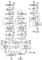
- Figure 6 shows the INITIALISE routine;
- Figure 7 shows the READY routine;
- Figure 8 shows the NMIR routine;
- Figure 9 shows the TSTGEN routine;
- Figures 10A and 10B show the GETNOI routine;
- Figure 11 shows the PULOUT routine;
- Figure 12A-12C show the ADJUST routine; and
- Figure 13 shows the PULFOUT subroutine.
- Figure 1 schematically illustrates a cutting apparatus comprising a rotating
cutter head 100 and an adjustable but fixedshear bar 102. By way of example only, the cutting apparatus may be the cutter head and shear bar of a forage harvester as illustrated in co-pending U.S. Patent Application Serial No. 784,391 (Patent No. 4,678,130). Theshear bar 102 is mounted on asupport bar 104 but is movable with respect to the support bar by actuation of linkages such as a pair oflead screws cutter head 100 carries a plurality of knives which, as the cutter head rotates, cooperate with theshear bar 102 to cut material passing between the cutter head and the shear bar. - A first
bidirectional motor 110drives lead screw 106 which is linked to a first end A of the shear bar. A secondbidirectional motor 112 driveslead screw 108 which is linked to a second end B of the shear bar. - Adjustment of the
shear bar 102 relative to thecutter head 100 is accomplished with the cutter head rotating. Atachometer 114 senses rotation of the cutter head shaft and produces a sequence of pulses indicating the cutter head speed which is applied to anelectrical control circuit 116. Adjustment is accomplished by sensing vibrations, or the absence of vibrations in thesupport bar 104 resulting from contact, or the lack of contact, between theshear bar 102 and the knives of the rotating cutter head. Avibration sensor 118, which may be a crystal, is attached to thesupport bar 104. The support bar has an internally threaded hole 120 (Figure 3) for receiving a threaded mounting stud provided on the crystal mount. - Since adjustment is accomplished by sensing vibrations resulting from contact between the
shear bar 102 and the knives of thecutter head 100, it is essential that shear bar adjustment not be attempted if thesensor 118 is not functioning. A solenoid-actuatedknocker 122 is provided for determining the operability of the knock sensor. Theknocker 122 has a threaded mounting stud which secures the knocker to an internally threadedhole 124 in thesupport bar 104. The solenoid has a spring-biased armature which carries animpact element 126 at its end. When the solenoid is energised it drives theimpact element 126 into contact with thesupport bar 104, inducing vibrations in the support bar which are sensed by thesensor 118. Theelectrical control 116 pulses theknocker 122 and analyses the signals returned by thesensor 118. - A push-
button switch 128 is provided on a control panel near the operator. Each time the operator actuates switch 128, theelectrical control circuit 116 checks the operability ofsensor 118 as well as its sensitivity, checks to determine that thecutter head 100 is rotating and selectively energises first one of themotors cutter bar 102 is essentially parallel to thecutter head 100 and spaced therefrom by no more than a small predetermined distance on the order of a few thousandths of an inch. - The
electrical control circuits 116 are illustrated in Figures 4A and 4B and include amicroprocessor 200, an EPROM 202, an analog-to-digital converter (ADC) 204, a peripheral interface adapter (PIA) 206, a versatile interface adapter (VIA) 208, an address decoder orselector 210 and awatch dog circuit 212. All units except the watch dog circuit are interconnected by an 8-bitbidirectional data bus 214 and/or a 16-bit address bus 216. - Since the details of the VIA 208,
microprocessor 200, EPROM 202, ADC 204, PIA 206, andaddress decoder 210 are well known in the art, they are not described in detail herein but a brief description of each is given below. - The
microprocessor 200 may be a Motorola type 6802 microprocessor including an internal memory for limited storage of data during a processing operation. The microprocessor has eight input/output terminals D7-D0 which are connected to thedata bus 214 and sixteen output terminals A15-A0 for supplying an address generated within the microprocessor to theaddress bus 216. When a data register within the microprocessor is loaded with a byte of data for application to the data bus the microprocessor drives the signal R/
lead 218 tologic 0 and when the data register is to receive a byte of data from the data bus the microprocessor causes the signal R/
logic 1. When the microprocessor places an address on the address bus it generates the signal Valid Memory Address (VMA) onlead 220 and this signal is applied to the gating input ofaddress decoder 210. The microprocessor outputs a single phase clock ontolead 222 from its E terminal. -
Microprocessor 200 has a non-maskable interrupt (NMI) input terminal. A low-going signal at this terminal causes themicroprocessor 200 to initiate a non-maskable interrupt sequence. Themicroprocessor 200 also has a reset input terminal
lead 230 goes to low the registers within the microprocessors are cleared and the microprocessor becomes inactive. When the signal at terminal
microprocessor 200 to begin a restart sequence. - Address bus bits A15-A13 are connected to input terminals of the
address decoder 210. Each time the microprocessor outputs a signal onlead 220, it enables the address decoder to decode the three address bits and produce a signal on one of the leads 223-226. Thelead 223 is connected to the
VIA 208.Lead 224 is connected to the

EPROM 202.Lead 225 is connected to the
ADC 204 whilelead 226 is connected to the
PIA 206. - The
EPROM 202 may be a type 2764 capable of storing 8K 8-bit bytes. When the signal onlead 224 is low the location in the EPROM specified by the address applied to the EPROM frombus 216 is accessed. The location is either written to from the microprocessor, or read out to the microprocessor, depending upon whether the signal R/
EPROM 202 stores data and the program which is executed by the microprocessor. - The
VIA 208 may be a type 6522 such as that manufactured by Rockwell or Synertek. As disclosed at page 2526-2530 of the publication IC Master 1980, published by United Technical Publications, theVIA 208 includes 16 addressable registers and interval timers or counters. These registers and interval timers are addressed by applying an address from the four low order of bits of theaddress bus 216 to the register select input RS3-RS0. Data is read from, or entered into the registers and counters through data terminals D7-D0 which are connected to thedata bus 214. The VIA is enabled only when the microprocessor outputs a hexadecimal address, the high order bits of which cause theaddress decoder 210 to produce a low signal onlead 223 which enables the chip select (
microprocessor 200 outputs a high or low level signal, respectively, onlead 218 to R/
lead 222 to the E terminal of themicroprocessor 200. All circuits withinVIA 208 are reset when the signal
lead 230 goes low. TheVIA 208 produces an output signal CB2 which is used for control purposes. The microprocessor program periodically sends a byte of control information toVIA 208 to toggle CB2 and pulse watchdog circuit 212. The watch dog circuit may be two monostable multivibrators connected in series. Periodic pulses produced on lead 232 by the VIA periodically reset the watch dog circuit so that its output remains inactive. If the program should fail to send signals to theVIA 208 so that lead 232 is pulsed, the watch dog circuit times out and emits an output signal to reset the microprocessor, the VIA and thePIA 206. Thewatch dog circuit 212 also has aninput 234 which is derived from a monitoring circuit (not shown) which monitors the logic circuit supply voltage. If this voltage should vary outside predetermined limits the signal onlead 234 cause thewatch dog circuit 212 to produce an output signal to reset the microprocessor, the PIA and the VIA. The 5V supply voltage for the circuits of Figures 4A and 4B may be derived from the 12V battery which supplies power for the harvester if it is self-propelled, or from the battery for the tractor which pulls the harvester. -
VIA 208 has two 8-bit input/output ports PA and PB. The bit positions of the ports are individually programmable as either an input or an output. Two buses, collectively designated 231, connect PA and PB to external circuits shown in Figure 4B. The port A bus is connected to receive the outputs of a plurality of amplifiers 241-244.Amplifier 241 has one input connected to the 5V logic supply voltage and a second input connected through tworesistors resistors switch 252 to ground. As long asswitch 252 is closed the amplifier applies alogic 0 signal to the bus but whenswitch 252 is open the amplifier applies alogic 1 signal to the bus. Theswitch 252 is associated with an engage lever (not shown) which is actuated so that a chain drive causes thecutter head 100 to rotate.Switch 252 is thus closed when drive power is applied to the cutter head. - Amplifiers 242-244 are arranged in the same manner as
amplifier 241, withswitches amplifiers amplifier 244. These switches are all limit switches for sensing when the ends of theshear bar 102 have reached their limits of travel toward or away from thecutter head 100.Switches shear bar 102 are at their limit of travel away from thecutter head 100.Switches amplifier 244 produces alogic 1 output when either switch is opened, i.e. when either end A or end B is at its limit of travel toward thecutter head 100. The limit switches 258, 260 are incorporated within the housings ofmotors lead screws - The tachometer 114 (Figure 1) produces a sequence of output pulses at a rate proportional to the speed of rotation of the
cutter head 100. The pulses are applied over a lead 262 (Figure 4B) to one input of a comparator amplifier 264. A voltage divider comprising tworesistors logic 1 signal to bit position 6 of the B bus. These pulses are counted by a counter (timer 2) inVIA 208. - Five bits of port B of the VIA are connected by a B bus to five inverters 270-274. The outputs of inverters 270-273 are connected to the bases of grounded emitter transistors 280-284, respectively. The collectors of transistors 280-283 are connected to the 12V source through the coils of relays K2-K5, respectively, while the collector of transistor 285 is connected to the 12V source through an
audible alarm 286. - The direction of rotation of
motor 110 is controlled by the contacts of relays K2 and K3, only one of which may be energised at any given time. If relay K2 is energised the motor rotates in one direction to move end A (Figure 2) of theshear bar 102 inwardly toward thecutter head 100. The current flow path extends from 12V through contacts K2a,motor 110, normally closed contacts K3b andresistor 288 to ground. On the other hand, if relay K3 is energised, a circuit extends from the 12V source through contacts K3a,motor 110, contacts K2b andresistor 288 to ground. Since current flow is in the opposite direction through the motor, it rotates in the opposite direction to move end A of theshear bar 102 away from thecutter head 100. If neither relay K2 or K3 is energised,motor 110 does not rotate because contacts K2a and K3a are both open. - Relays K4 and K5 have normally open contacts K4a and K5a and normally closed contacts K4b and K5b. Relays K4 and K5 control the
motor 112 in exactly the same manner that motor 110 is controlled by relays K2 and K3. -
Bit 7 of port B ofVIA 208 is controlled by one of the timers inVIA 208. The timer (TIC) causes an interrupt pulse to appear at PB7 each time the counter is loaded, the delay between the loading of the counter and the occurrence of the pulses being determined by the value entered into the counter. PB7 is connected by a lead 235 to the
microprocessor 200 so that the program being executed by the microprocessor is interrupted periodically and a routine is executed to read the various switches and output various control signals to the VIA and PIA buses. - One bit of the PB bus is connected to a
type 3548 PNP drive circuit. The output of the driver circuit is connected to ground through the solenoid ofknocker 122. As subsequently explained, the solenoid is energised to induce vibrations in theshear bar 104 and the resulting vibrations sensed bysensor 118 are analysed to determine its operability. - The
PIA 206 may be a type 6821 peripheral interface adapter. This device is well known in the art and is generally similar toVIA 208 except that it does not include timers.PIA 206 has two 8-bit ports PA and PB connected to an A bus and a B bus, collectively illustrated asbuses 300. The bit positions of the ports are individually programmable for input or output. Only 2-bit positions of port A are utilised and they are programmed as inputs. These bit positions receive the outputs of the twoamplifiers quit switch 306 is connected between ground and one input ofamplifier 302 so that when the switch is closed the amplifier applies alogic 1 signal to the PIA over the bus.Switch 306 is actuated to halt or interrupt a shear bar adjusting operation. - The
switch 128 is connected to one input ofamplifier 304 and when this switch is actuated the amplifier applies alogic 1 signal to the PIA over the bus.Switch 128 is the ADJUST switch which initiates a shear bar adjusting sequence. - Only seven bits of port B of
PIA 206 are utilised and they are all programmed as outputs. Each bit is connected through adriver 310 and anLED 314 to 12V. The LEDs provide an operator with visual alarms or indications of the status of the system by indicating that the system is ready to begin an adjusting cycle;switch 306 has been actuated to interrupt an adjusting cycle; amotor sensor 118 is bad; or a shear bar adjusting operation is in progress. -
ADC 204 may be a type 0844 converter such as that described at page 3537 of the publication IC Master, Vol. 2, 1984. The converter has four multiplexed input channels but only CH1, CH2 and CH4 are utilised in the present invention. The converter is enabled only when the address applied toselector 210 bymicroprocessor 200 causes the signal onlead 225 to be low. This lead is connected to the CS terminal of the converter. - The
microprocessor 200 starts a converter cycle by placing a command ondata bus 214 to select the channel, and drivinglead 218 low.Lead 218 is connected to one input of twoNANDs NAND 320 is connected to +5V and the output of the NAND is connected to afurther NAND 324. The E output ofmicroprocessor 200 is connected to one input ofNANDs 

lead 218 is low,NAND 324 produces a low output when the clocking signal onlead 222 goes high. The output ofNAND 324 enables the converter so that the operation specified by the command is carried out. - It takes the converter about 40 microseconds to convert an analog value to a digital value. The programming of
microprocessor 200 is such that once it initiates a cycle ofconverter 204 it either waits or performs other operations until at least 40 microseconds have elapsed. Themicroprocessor 200 then places an address onbus 216 so thatselector 210 produces a signal onlead 225 to select the converter. At the same time, themicroprocessor 200 drives the signal onlead 218 high. When the clock signal onlead 222 goeshigh NAND 322 produces an output signal which enables the converter to place the converted value onbus 214 from whence it passes to themicroprocessor 200. - The analog signal from
knock sensor 118 is applied to the CH1 input of the A/D converter through a circuit (Figure 5) includingresistors amplifiers peak hold circuit 334 and abuffer amplifier 336. A pair ofresistors 331, 333 provide a first reference voltage which is added to the knock sensor output signal, the output ofamplifier 330 being proportional to the sum of the reference signal and the differential signal derived from the sensor. A second reference voltage is derived from a voltagedivider comprising resistors amplifier 340 and the output of the amplifier is tied to ajunction 338 between thepeak hold circuit 334 andbuffer amplifier 336. - The output of
amplifier 341 is also applied to the CH4 input ofADC 204. TheADC 204 is controlled to operate in a differential mode so that it determines the difference in the magnitude of the analog signals at CH1 and CH4 and converts this difference to a digital value for transmission to themicroprocessor 200. -
Resistors amplifier 346. The output of this amplifier is applied to the Vr input ofADC 204 to set the range of the converter. - During a shear bar adjusting
operation motors 110 and 112 (Figure 4B) control the movement of theshear bar 102. As previously explained, the circuit for energising eithermotor current sensing resistor 288. Thus, by sampling the voltage across theresistor 288 it is possible to determine if either motor is stalled or if the motor which should be running is not actually energised. The voltage developed acrossresistor 288 is applied through anoperational amplifier 340,filter circuit 342, andbuffer amplifier 344 to the CH2 input ofADC 204 where it may be sampled. The ADC does not subtract the magnitude of the CH4 signal from the CH2 before doing an ADC. - When power is turned on the
microprocessor 200 automatically goes through an initialisation routine (Figure 6) during which the various registers and timers in the VIA and PIA are set up. This routine also clears the switch registers or locations inmemory 202 which store indications of the last sampled state of the various switches. The routine then clears the QUIT, PULSW, and RPMOK flags and sets a FIRST flag. In addition, flags are set to turn off the alarm and alarm lights as well as the sensor light. The stack in themicroprocessor 200 is initialised after which the program proceeds to the first step of the READY routine. - The READY routine is illustrated in Figure 7. It begins at
step 700 by setting the flag POUTF. The ready light flag is set so that the ready light may be turned on when the NMIR routine is next executed. The sensor light flag is cleared so that the sensor light will be turned off thenext time VIA 208 pulses thewatchdog circuit 212. The BUSY and ALFLG flags are cleared after which the program proceeds to step 702 where it executes a wait for interrupt instruction. At about 2.5MS intervals a pulse occurs at PB7 of theVIA 208 thereby pulsing the
microprocessor 200. The microprocessor interrupts the routine it is executing, in this case the READY routine, and executes the NMIR routine illustrated in Figure 8. - At
step 800, the NMIR routine loads the counter TIC inVIA 208. This counter is decremented and when it reaches zero it will again pulse PB7 of the VIA to initiate another NMIR routine. The VIA next senses the QUIT and ADJUST switches and sets flags indicating which switches are actuated. In addition, if both switches are actuated a flag PULSW is set. The microprocessor then addresses theADC 204 to initiate a read-convert cycle with CH2 as the selected input. This samples the motor current and converts it to a digital value. - At
step 801 the CLFLG flag is tested to see if the clutch in the cutter head drive chain has been engaged to actuateclutch switch 252. If it has not, a flag is set to turn on one of the indicator lights 314 to indicate that the RPM of the cutter head is not within limits, and the program branches to step 812 to turn on the indicator. A return is then made to the routine which was interrupted. - If CLFLG indicates that the clutch is engaged, the program proceeds to step 802 where the FIRST flag is tested. This flag was set during the INIT routine so the program proceeds from step 802 to step 804 where FIRST is cleared and a value is set into RPMFLG. This value will be counted down to time the interval during which tachometer pulses produced by the
cutter head tachometer 114 will be counted bytimer 2 inVIA 208. - At
step 806 RPMLFG is tested to see if the timing interval has elapsed. Assuming it has not, the program decrements RPMFLG atstep 808 and atstep 810 the converted value of the current flowing through the shear bar adjusting motors is read fromADC 204 and saved. Atstep 812 the program sends data toPIA 206 to turn on the appropriate indicator lights. The program then returns to the routine which is interrupted to execute the instruction following the last instruction executed before the interrupt. - In Figure 7,
steps step 704 indicates that a preset interval of time has elapsed. The program then tests the ADJSW flag at 706 and the PULSW flag atstep 708. Assuming that the ADJUST switch is not actuated either alone or concurrently with the QUIT switch, the program executes another Wait For Interrupt atstep 710 and then loops back tostep 700. Thus, assuming the ADJUST switch is not actuated the READY routine is repeatedly executed, the routine being interrupted every 2.5MS to execute the NMIR routine. Because FIRST is cleared atstep 804 during the first execution of the NMIR routine after the cutter head clutch is engaged, the program branches from step 802 to 806 on the second and subsequent executions of the routine. RMPFLG is decremented atstep 808 each time the NMIR routine is executed and after 255ms RPMFLG is reduced to zero. The test atstep 806 proves true and the program moves to step 814 where the count of tachometer pulses accumulated bytimer 2 inVIA 208 is read and saved, and RPMFLG is reloaded to time another 255ms interval. - RPMMIN is a value representing the minimum permissible rate of rotation of the
cutter head 100. Atstep 816 RPMMIN is compared with count of tachometer pulses. If the count is equal to or greater than RPMMIN the RPMOK flag is set atstep 818. If the count is less then RPMMIN then RPMOK is cleared atstep 820. Afterstep ADC 204 is addressed to again get the converted value of the adjusting motor current. - The purpose of the TSTGEN subroutine to check the operability of the
knock sensor 118 and its associated circuitry. The TSTGEN subroutine is illustrated in Fig. 9 and begins atstep 900 where TSTS is set to 3, SAMPLE is set to 64, and OKTST is cleared. At step 901 a value is sent to VIA which causes the VIA to output a signal over its B bus to energisedriver 275 thereby energising theknocker solenoid 122. In Fig. 3, theclapper 126 is driven againstsupport bar 104. This induces vibrations in the support bar which may be sensed byknock sensor 118 to produce an analog signal. This signal passes through the circuit of Fig. 5 and is applied to the CH1 input ofADC 204. - At
step 902 the microprocessor addresses the ADC and starts a conversion cycle. Atstep 903 the microprocessor executes a delay loop waiting for 40 microseconds while the ADC samples the CH1 and CH4 inputs and converts the difference into a digital value. Atstep 904 the microprocessor addresses the ADC and saves the digital value which is an indication of the output of the knock sensor. - The program then enters a loop comprising steps 905-910. At
step 905 another analog-to-digital conversion cycle is started, atstep 906 the microprocessor waits for completion of the conversion cycle, and atstep 907 the converted value is retrieved from the ADC. Step 908 compares the latest (next) sample value with the previously converted value saved and the larger of the two values is saved. The value of SAMPLES is decremented and tested atstep 910 and if it is not decremented to zero the program loops back tostep 905. Thus, for one test the knocker solenoid is pulsed once at step 901 to induce vibration into the shear bar support and the output of the knock sensor is sampled 64 times, the largest of the 64 samples being saved atstep 909. After the 64th sample the test atstep 910 proves true and the program proceeds to step 911 where the saved largest sample is compared with a value representing the minimum acceptable magnitude for the signal output of the knock sensor. - If the largest sample is greater than or equal to the minimum acceptable magnitude OKTST is incremented at
step 912 before TSTS is decremented atstep 913. If the largest sample is less than the minimum acceptable magnitude the program branches from step 911 to step 913 without incrementing OKTST. - At step 914 TSTS is sampled to see if it has been decremented to zero. If it has not, the program branches back to step 901 to again pulse the knocker and determine the largest of the next 64 samples taken of the output of the knock sensor.
- After three tests have been completed the test at step 914 proves true and at
step 915 OKTST is sampled to see if it is still zero. If it is not, it means that the knock sensor test was successful and found at least one sample larger than the required minimum value. If OKTST is still zero it means that the knock sensor is not sensitive enough to be used, or its output circuitry is not functioning properly. The program branches to step 916 to set flags to turn on anindicator 314 and thealarm 286. A jump is then made to an alarm routine to sound the alarm and turn off the motors. Although the ALARM routine is not illustrated, it may be noted that the program continuously executes a loop in the ALARM routine until the operator turns the power off and then on so that the program again executes the INITIALISE routine illustrated in Fig. 6. - The subroutine GETNOI is illustrated in Figs. 10A and 10B. During execution of this routine the output of the knock sensor is tested up to four times, each test comprising 4096 samples. The maximum number of tests is set at step 1000 and the number of samples is set at
step 1009. The purpose of GETNOI is to determine the noise vibrations induced in the shear bar as a result of normal machine operation, or more specifically the output of the knock sensor in response to these vibrations. The subroutine develops a digital indication of the noise and this digital indication is subsequently used in the ADJUST routine described below to set the sensitivity of the system to the output signal from the knock sensor. - At
step 1001 the RPMOK flag is tested. This flag is set atstep 818 of the NMIR routine if the cutter head speed is equal to or greater than the minimum speed represented by RPMMIN. If the cutter head is not up to speed the program branches to step 1002 where a flag is set to turn on the alarm. Atstep 1003 the program executes a Wait For Interrupt and after NMIR is executed to again sample the speed of the cutter head the program branches back tostep 1001. The loop 1001-1003 is repeated until the speed of the cutter head is above the preselected minimum speed RPMIN. When the speed is satisfactory the NMIR routine will set RMPOK and upon return to GETNOI the test atstep 1001 will prove true. The program then turns off the alarm flag atstep 1004 and atstep 1005 jumps to the PULOUT subroutine, subsequently described, which controls theshear bar 102 adjustingmotors cutter head 100. This insures that there will be no contact between the cutter head and shear bar while the noise test is being made. Since the PULOUT routine energises only one motor each time it is executed,step 1005 actually represents two executions of the subroutine. - At
step 1006 the program jumps to the TSTGEN subroutine to test the operability of the knock sensor and its output circuitry. Atsteps -
Step 1009 clears two locations designated HIGH and RAVG, and sets SAMPLES to 4096. The program then enters a loop comprising steps 1010-1014. Atstep 1010 the program jumps to a RDSENS subroutine. This subroutine is not illustrated but comprises steps equivalent to steps 902-904. That is, it starts a conversion cycle to sense and convert the output of the knock sensor (minus the input to CH4) to a digital value, waits until the conversion is completed, and reads the converted sensed value from the ADC. Atstep 1011 this sensed value is compared with HIGH and the larger value is saved at HIGH.Step 1012 adds the sensed value to RAVG which is an accumulated sum of all sensed values. Atstep 1013 SAMPLES is decremented and atstep 1014 it is tested to see if 4096 samples have been taken. If not, the program loops back tostep 1010. - When 4096 samples have been taken, the program saves the largest of the samples at DATA2. The value in RAVG is tested by dividing it by a fixed value and testing the quotient to see if it exceeds a limit. If it does, it is an indication that there is too much background noise so the program branches to step 1022.
- The occurrence of too much noise is not the only reason a noise test may fail. If the highest value sensed during the 4096 samples exceeds a predetermined maximum value it means that there is not enough "headroom". That is, when the output of the knock sensor resulting from contact between the cutter head and shear bar is added to the highest noise value, it will exceed the maximum input signal which the ADC can convert. The contents of HIGH are compared to MAXN and if MAXN is smaller the program branches to step 1022.
- A noise test will also fail if the highest noise value sensed exceeds the average noise value of all the samples by more than a fixed value NMRG. RAVG is added to NMRG and saved at DATA3. HIGH is then compared to the resulting sum at
step 1020 and if HIGH is greater the program branches to step 1022. - If a noise test fails for any reason, CYCLES is decremented at
step 1022 and tested atstep 1023. If it has been decremented to zero the program sets the alarm flag atstep 1024 and jumps to the alarm routine. If four tests have not been completed the program branches fromstep 1023 back tostep 1001. - If any test proves successful, then no further tests are made. If a test is successful then the test at
step 1020 will prove false and the program proceeds to step 1021 where HIGH is added to MARG to obtain a "noise value". In effect, the ADJUST routine described below assumes that any output signal from the knock sensor less than this value is due to noise alone. the noise value is saved at NOI2, the POUTF flag is cleared, and a return is made to the calling routine. - The PULOUT subroutine shown in Fig. 11 is called for the purpose of moving one end of the
shear bar 102 out, i.e. away, from thecutter head 100 by a given amount. At the time the subroutine is called the microprocessor A register holds an indication of which motor 110 or 112 is to be energised and in what direction, and the X register holds a value CYCLES indicating how many 1/4-second intervals the motor is to be energised. - The subroutine begins at step 1100 by checking POUTF. If the flag is set the program branches to step 1102 where QSEC is loaded with a value indicating 1/4-second. QSEC is decremented at
step 1113 each time the loop comprising steps 1105-1116 is executed, and reaches zero after 1/4 second. - At step 1103 the microprocessor sends the motor indication to the output register of
VIA 208 controlling port B. A signal is produced on the B bus to energise one of the relays K3 or K5 so that one of themotors shear bar 102 away from thecutter head 100. - At
step 1104 two counter locations HCNTR and LCNTR are loaded with values for timing high current and low current intervals. The motor current is checked as subsequently described to see if it exceeds a predetermined maximum value (e.g. the motor is stalled) or is less than a predetermined minimum value, (e.g. motor winding circuit is open). If it exceeds the maximum value for an interval of time corresponding to the count set in HCNTR or is less than the minimum value for an interval of time corresponding to the count set in LCNTR, the subroutine is terminated and an alarm condition indicated. - At
steps step 1107 the saved current value is compared with a reference value to see if the current is too high. Assuming the motor current is not too high, HCNTR is reloaded atstep 1108 to restart the high current timing interval. - At
step 1109 the current value is compared to a minimum reference value to see if it is too low. Assuming it is not, LCNTR is reloaded atstep 1110 to restart the low current timing interval.Steps 1111 and 1112 merely waste time so that the loop comprising steps 1105-1114 takes .01 second. Atstep 1113 QSEC is decremented and at step 1114 it is tested to see if it has reached zero. Assuming it has not, the program branches back tostep 1105 and repeats the loop. - After 1/4 second the test at step 1114 proves true so the program moves to step 1115 where QSEC is reloaded to time another 1/4 second interval, and CYCLES is decremented. CYCLES is then tested at
step 1116 to see if the required number of 1/4 second intervals have elapsed. If not, the program branches back tostep 1105. If the required number of 1/4 second intervals has elapsed then the required movement of the motor is complete. At step 1117 the microprocessor sends a value to the output register ofVIA 208 which turns off any motor that is on. A return is then made to the calling routine.V - If the test at step 1100 shows that POUTF is not set then the program tests the EOTOUT flag to see if either of the
limit switches - If the test at
step 1107 shows that the motor current is too high, the program branches to step 1120 where HCNTR is decremented. HCNTR is then tested at 1121 to see if the high current condition has existed for too long a time. If it has not, the program moves to step 1111 and proceeds as described above. If the high current condition persists for too long a time, HCNTR will be decremented to zero and the test atstep 1121 will prove true. In this case flags are set to turn on astall indicator 314 and sound thealarm 286, after which the program jumps to the alarm routine. - Steps 1130-1132 serve the same purpose as steps 1120-1122 except that they time the interval the motor current is below the required minimum.
- The ADJUST routine controls the motors M1 and M2 to adjust the shear bar relative to the cutter head. The program jumps to the ADJUST routine from
step 706 of the READY routine if the adjust switch 308 has been actuated. The ADJUST routine begins atstep 1200 where the BUSY flag is set and the READY LIGHT flag is reset so thatindicators 314 will properly indicate the status of the system. The location TIMS is set to 2. If energisations of themotors rotating cutter head 100 and theshear bar 102 TIMS is decremented and when TIMS=0 the adjustment is complete. Certain flags such as IMP1, IMP2 and HITFLG are cleared atstep 1200. - At
step 1201 EOTIN is tested to see if one of theswitches shear bar 102 is at its limit of travel toward thecutter head 100. If neither switch is actuatedstep 1202 checks the RPMOK flag to be sure that the cutter head is rotating faster than a predetermined minimum speed. Assuming that the rpm is satisfactory the program clears the flag for setting theRPM indicator 314. - The program jumps at
step 1204 to the TSTGEN subroutine to test theknock sensor 118 and its output circuitry as previously described. Upon the return from this subroutine the program jumps to the GETNOI subroutine to determine the background noise. - At step 1206 the microprocessor fetches M1IN and sets WICHMO to indicate that motor M1 is active. The program then obtains ONTIME, the number of 1/4 second intervals the motor M1 is to be energised. M1IN is then sent to
VIA 208 and the VIA produces an output signal over its bus to energise relay K2 thereby energising motor M1 in a direction which moves end A (Fig. 2) of theshear bar 102 toward thecutter head 100. -
Step 1208 sets QSEC totime 1/4 second.Steps 1209 and 1210 introduce a 100MS delay to allow electrical transients resulting from the motor energisation to die down after which a jump is made to the RDSENS subroutine to sample the output of the knock sensor and convert it to a digital value. Atstep 1212, this value is compared with the value of NOI2 obtained during execution of GETNOI atstep 1205. If the knock sensor output value is greater than NOI2 it indicates that the cutter head is hitting the shear bar so that program branches to Fig. 12C. - Assuming that the sensor output value is less than NOI2, no hit has occurred so the program proceeds from
step 1212 to step 1213 where the motor current value obtained during the last execution of the NMIR routine is compared to a value representing the maximum allowable current. If the motor current does not exceed the maximum allowable value then atstep 1215 it is compared with a value representing the minimum allowable current. It may be noted that steps 1213-1222 of the ADJUST routine correspond exactly with steps 1107-1113, 1120-1122 and 1130-1132 of the PULOUT subroutine described above. - If the checks of the motor current show that it is within the prescribed limits then at
step 1224 the EOTIN flag is checked to see if the motor has driven the end of the shear bar to its inward limit of travel. If it has not, the RPMOK flag is checked to see if the cutter head is still rotating. Assuming it is, QSEC is decremented at 1226 and then tested at 1227 to see if 1/4 second has elapsed. - If the test at
step 1227 shows that 1/4 second has not elapsed then the program loops back tostep 1211 and repeats the loop comprising steps 1211-1216 and 1224-1227. When 1/4 second has elapsed the test atstep 1227 proves true and the program moves to step 1228 where it resets QSEC to time another quarter-second interval and decrements ONTIME, the number of quarter second intervals that the motor is to be on. In a typical system ONTIME may be about 10 such intervals. - After ONTIME is decremented it is tested at
step 1229 to see if the motor energising interval has expired. If it has not, the program loops back tostep 1211. If the energising interval has expired the program moves to step 1262 (Figure 12C) where the flags IMP1, IMP2 and HITFLAG are cleared. The program then proceeds to step 1230 (Figure 12D) where the microprocessor sends a code toVIA 208 which terminates the output signal for energising relay K2. When relay K2 opens motor M1 stops. A jump is then made to the TSTGEN subroutine to check the operation of the knock sensor before beginning the movement of the other motor. Upon the return from TSTGEN the location WICHMO is tested to see if M1 or M2 was the motor whose movement was just completed. If WICHMO indicates M1 then atstep 1233 it is set to indicate M2 and the code is obtained for controlling M2 to move the shear bar inwardly toward the cutter head. On the other hand, if the test atstep 1232 should indicate that WICHMO is set to M2 then atstep 1234 it is set to indicate M1 and a code is obtained for controlling M1 to move the shear inwardly. After completion ofstep step VIA 208 to energise either relay K2 or K4 and thereby activate motor M1 or M2 to move its end of the shear bar inwardly toward the cutter head. - Depending on the position of the shear bar at the time the adjusting procedure is initiated, M1 and M2 may be alternately energised one or more times as described above without driving either end of the shear bar into contact with the rotating cutter bar. Eventually however energisation of one of the motors will result in contact. When RDSENS is executed at
step 1211 to read the knock sensor output, this output will be larger than NOI2. Therefore, when the knock sensor output is compared to NOI2 atstep 1212 the program recognises the hit and branches to step 1240 (Fig. 12C) where a code is sent toVIA 208 which deenergises all relays K2-K5 thereby stopping all motors. Atstep 1241 WICHMO is checked to see which motor caused the hit. If it was M1 then the flag IMP1 is set atstep 1242. IMP1 and IMP2 are checked atstep 1243 to see if both have been set. If both IMP1 and IMP2 are set then HITFLG is set at 1244 beforestep 1245 is executed. If IMP1 and IMP2 are not both set then the program branches fromstep 1243 to 1245. - At
step 1245 the flag POUTF is cleared, the code for moving M1 outwardly is fetched to the microprocessor A register and BOUT, the number of quarter-second intervals the motor is to be energised, is loaded into the microprocessor X register. BOUT may be on the order of 5 such intervals. A jump is then made to the PULOUT subroutine to energise M1 in a direction to move theshear bar 102 away from thecutter head 100. - Upon return from the PULOUT subroutine HITFLG is tested. If it is not set, i.e. there has not been at least one impact by each of the motors, the program moves to step 1248 where the TSTGEN subroutine is executed to test the knock sensor. At
step 1249 WICHMO is set to indicate M2, QSEC is reset to time a quarter-second interval, and the code is obtained for controlling the motor M2 to move the shear bar inwardly. The program then branches back to step 1207 where the motor is turned on by sending the code to theVIA 208. - Returning to step 1241, if the test shows that WICHMO is set to indicate M2 then the program branches to step 1252. Steps 1252-1259 correspond to steps 1242-1249 the only differences being that the flag IMP2 is set at
step 1252, the code for energising M2 is obtained atstep 1255, and WICHMO is set to M1 and the code for energising M1 is obtained atstep 1259. - If a test at
step - If the test at
step 1261 proves true it means that the adjusting sequence is complete. A flag is set atstep 1263 to beep thealarm 286, and the program then jumps to the READY routine. - It has been found that after two "hits", i.e. after impacts have twice caused HITFLG to be set, the shear bar is spaced on the order of .005 (0.127mm) to 0.010 inch (0.254mm) from the cutter head and essentially parallel thereto. The gap between the
shear bar 102 and thecutter head 100 at the end of the adjusting procedure is governed in large part by the value of BOUT atstep steps - If the test at
step 12012 or 1224 shows that the EOTIN flag is set, it means that one of the end oftravel switches indicators 314 to indicate EOT and sound an alarm, and then jumps to the ALARM routine. In like manner, if the RPMOK flag is not set when the test is made atstep 1225, the programs sets appropriate flags to turn on the RPM indicator and the alarm, and jumps to the ALARM routine. - At
step 1202, the RPMOK flag is tested prior to any motor actuation. If the flag is not set the program sets flags for giving the alarm indication atstep 1281 tests the QUIT flag to see if the operator has depressed the Quit switch. If he has, the program jumps to the Ready routine. If he has not, a Wait for Interrupt is executed during the wait. The program then branches back to step 1202 to again check the RPMOK flag. If the cutter head is up to speed the program then clears the alarm flags atstep 1203. - It will be recognised by those skilled in the art that by properly programming the
VIA 208 so that some bus bit positions alternatively serve as input or output, it would be possible completely to dispense with thePIA 206. Thus, there is wide latitude in programming the control of the various indicators and alarms. For this reason the ALARM routine is not specifically described. ThePIA 206 becomes necessary only when additional control features such as an automatic knife sharpener control are added into the system. - As previously indicated, the PULSW flag is set if the Quit and Adjust switches are actuated concurrently. By actuating both switches the operator may initiate the PULFOUT routine which moves each end of the
shear bar 102 to its limit of travel away from thecutter head 100. - If the test at
step 708 shows that PULSW is set the program jumps to the PULFOUT routine shown in Fig. 13. Atstep 1300 the Busy and POUTF flags are set, the length of time for energising the motor is loaded in the microprocessor X register, and the code for energising M1 to move the shear bar outwardly is entered in the A register. The program then jumps to the PULOUT subroutine to energise M1. Upon the return to PULFOUT EOTOUT1 is tested to see if end A of the shear bar is at its limit of travel. If not, the QUIT flag is tested at 1303. Assuming the Quit switch has not been actuated by the operator the microprocessor gets the control values for moving motor M2 outwardly (step 1304) and executes the PULOUT subroutine at step 1305 to move end B of the shear bar. Step 1306 tests EOTOUT2 to see if end B of the shear bar is at its limit of travel and if it is not the QUIT flag is tested atstep 1307. - If the Quit switch is not depressed the program branches back to the beginning of the subroutine and continues executing the steps described above. When end A of the shear bar reaches its outward limit of travel the test at 1302 proves true and the program branches to turn off the motor (step 1308) and set the flag for beeping the alarm (step 1309). The program then jumps to the READY routine. The program also branches to step 1308 if the test at step 1306 indicates that end B of the shear bar is at its outward limit of travel.
- The PULFOUT subroutine may be halted by depressing the Quit switch alone. This sets the QUIT flag so that the program will branch from
step 1303 or 1307 to step 1308, thus ending the pullout operation. - In summary, the present invention provides a completely automatic control for adjusting the position of a shear bar relative to a rotating cutter head by alternately energising first one and then the other motor alternately to move first one end of the shear bar and then the other. The system includes a knocker for inducing vibrations into the shear bar so that the operability of the knock sensor and its associated circuitry may be automatically checked. The system also automatically checks "noise" vibrations in the shear bar and adjusts the sensitivity of the system to the output signal from the knock sensor.
Claims (12)
- A method of adjusting clearance between members of a forage harvester having a pair of members (100, 102) for processing material introduced therebetween, a first adjuster (110) connected to a first end of one of the members (102), a second adjuster (112) connected to a second end of the one member (102) and a control unit (116) cooperable with the adjusters (110, 112) for automatically adjusting the clearance between the members;
the method being characterised in that it comprises the steps of :
automatically moving the first end of the one member (102) towards the other member (100) until the first end engages the other member, then automatically moving the first end a first distance away from the other member (100);
automatically moving the second end of the one member (102) towards the other member (100) until the second end engages the other member, then automatically moving the second end the first distance away from the other member;
automatically moving the first end of the one member (102) towards the other member (100) until the first end re-engages the other member, then automatically moving the first end a second distance away from the other member; and
automatically moving the second end of the one member (102) towards the other member (100) until the second end re-engages the other member, then automatically moving the second end the second distance away from the other member. - A method according to claim 1, characterised in that said one member is a shear bar (102) and said other member is a cutter head (100) and in that the method comprises the further steps of :
providing sensor means (118) for sensing vibrations in the shear bar (102);
inducing vibrations in the shear bar (102) which may be sensed by the sensor means (118);
producing an electrical signal representative of said vibrations;
comparing said representative signal with a reference value and
energising indicator means if the representative signal is less than the reference value. - A method according to claim 2, characterised in that it comprises the further steps of :
automatically adjusting said clearance when said representative signal exceeds said reference value and
automatically halting said automatic adjustment when said representative signal is less than said reference value. - A method according to claim 3, characterised in that it comprises the further step of repeatedly checking the operability of the vibration sensor means (118) before and during the shear bar adjustment operation.
- A method according to any of the claims 2 to 4, characterised in that :
it comprises the further step of converting the analogue output of the sensor means (118) to a digital value indicative of the magnitude of output signals produced by the vibration sensor in response to vibrations in the shear bar;
the comparing step consists of comparing said digital value with said reference value and
the energising step consists of energising the indicator means if this digital value is less than the reference value. - A method according to any of the claims 2 to 5, characterised in that it comprises the further step of :
adapting the threshold of the vibration sensor (118) in accordance with the level of background noise resulting from normal operation of the forage harvester whereby vibrations in the shear bar (102) resulting from contact with the cutter head (100) are distinguished from vibrations resulting from said background noise. - A method according to claim 6, characterised in that it comprises the further steps of :
sensing said background noise in the shear bar (102) detected by the vibration sensor (118);
developing a digital indication of this background noise;
adding a safety factor to said digital value to obtain a sensitivity level value;
sampling the vibration sensor output signal during movement of the shear bar (102) towards the cutter head (100) for evidence of contact between the shear bar (102) and the cutter head (100) and
stopping movement of the shear bar (102) towards the cutter head (100) when the sampled output signal exceeds the sensitivity level value. - A method according to any of the preceding claims, characterised in that the first and second adjusters are in the form of motors (110, 112) and in that the method comprises the further step of :
sensing the magnitude of current flowing through the first and second motors (110, 112) and de-energising the motors if the magnitude is above or below a predetermined range for a predetermined interval of time. - A method according to claim 8, when appended to claim 2, characterised in that it comprises the further step of:
sensing the rate of rotation of the cutter head (100) and de-energising the first and second motors (110, 112) if the rate of the rotation is less than a predetermined minimum rate. - A method according to claim 9, characterised in that it comprises the further step of :
repeatedly checking the rate of rotation of the cutter head (100) before and during the shear bar adjustment operation. - A method according to claim 2 or any of the claims 3 to 10 when appended thereto, characterised in that it comprises the further step of :
automatically stopping movement of the shear bar (102) if the first or second adjuster (110, 112) operates for at least a certain time period without engagement between the shear bar (102) and the cutter head (100). - A method according to claim 11, characterised in that said step of automatically stopping shear bar movement comprises the further steps of :
setting a count in a counter,
modifying at fixed intervals of time the value in the counter while the shear bar (102) is moving towards the cutter head (100) and
de-energising the first and second adjusters (110, 112) when the counter contains a second predetermined value.
Applications Claiming Priority (3)
| Application Number | Priority Date | Filing Date | Title |
|---|---|---|---|
| US46011 | 1987-05-05 | ||
| US07/046,011 US4799625A (en) | 1987-05-05 | 1987-05-05 | Method and apparatus for adjusting a shear bar relative to a cutter head |
| EP88303989A EP0291216B1 (en) | 1987-05-05 | 1988-05-03 | Method and apparatus for adjusting a shear bar relative to a cutter head |
Related Parent Applications (1)
| Application Number | Title | Priority Date | Filing Date |
|---|---|---|---|
| EP88303989.3 Division | 1988-05-03 |
Publications (3)
| Publication Number | Publication Date |
|---|---|
| EP0510781A2 true EP0510781A2 (en) | 1992-10-28 |
| EP0510781A3 EP0510781A3 (en) | 1993-03-10 |
| EP0510781B1 EP0510781B1 (en) | 1996-07-03 |
Family
ID=21941082
Family Applications (9)
| Application Number | Title | Priority Date | Filing Date |
|---|---|---|---|
| EP92202289A Expired - Lifetime EP0510780B1 (en) | 1987-05-05 | 1988-05-03 | Forage harvester |
| EP92202290A Expired - Lifetime EP0510781B1 (en) | 1987-05-05 | 1988-05-03 | Method for adjusting two members of a forage harvester |
| EP95201868A Expired - Lifetime EP0679330B1 (en) | 1987-05-05 | 1988-05-03 | Forage harvester having automatic shear bar adjustment mechanism including safety features |
| EP92202291A Expired - Lifetime EP0509620B1 (en) | 1987-05-05 | 1988-05-03 | Cutting apparatus |
| EP95201869A Expired - Lifetime EP0676131B2 (en) | 1987-05-05 | 1988-05-03 | Method and apparatus for adjusting a shear bar in a cutting apparatus using a vibration sensor |
| EP95201870A Expired - Lifetime EP0676132B1 (en) | 1987-05-05 | 1988-05-03 | Method and apparatus for adjusting a shear bar in a forage harvester |
| EP88303989A Expired - Lifetime EP0291216B1 (en) | 1987-05-05 | 1988-05-03 | Method and apparatus for adjusting a shear bar relative to a cutter head |
| EP92202288A Expired - Lifetime EP0511724B1 (en) | 1987-05-05 | 1988-05-03 | Forage harvester |
| EP95202886A Expired - Lifetime EP0706752B1 (en) | 1987-05-05 | 1988-05-03 | Shear bar adjustment apparatus including vibration sensor means with adjustable threshold |
Family Applications Before (1)
| Application Number | Title | Priority Date | Filing Date |
|---|---|---|---|
| EP92202289A Expired - Lifetime EP0510780B1 (en) | 1987-05-05 | 1988-05-03 | Forage harvester |
Family Applications After (7)
| Application Number | Title | Priority Date | Filing Date |
|---|---|---|---|
| EP95201868A Expired - Lifetime EP0679330B1 (en) | 1987-05-05 | 1988-05-03 | Forage harvester having automatic shear bar adjustment mechanism including safety features |
| EP92202291A Expired - Lifetime EP0509620B1 (en) | 1987-05-05 | 1988-05-03 | Cutting apparatus |
| EP95201869A Expired - Lifetime EP0676131B2 (en) | 1987-05-05 | 1988-05-03 | Method and apparatus for adjusting a shear bar in a cutting apparatus using a vibration sensor |
| EP95201870A Expired - Lifetime EP0676132B1 (en) | 1987-05-05 | 1988-05-03 | Method and apparatus for adjusting a shear bar in a forage harvester |
| EP88303989A Expired - Lifetime EP0291216B1 (en) | 1987-05-05 | 1988-05-03 | Method and apparatus for adjusting a shear bar relative to a cutter head |
| EP92202288A Expired - Lifetime EP0511724B1 (en) | 1987-05-05 | 1988-05-03 | Forage harvester |
| EP95202886A Expired - Lifetime EP0706752B1 (en) | 1987-05-05 | 1988-05-03 | Shear bar adjustment apparatus including vibration sensor means with adjustable threshold |
Country Status (4)
| Country | Link |
|---|---|
| US (1) | US4799625A (en) |
| EP (9) | EP0510780B1 (en) |
| CA (1) | CA1331044C (en) |
| DE (9) | DE3855399T2 (en) |
Families Citing this family (78)
| Publication number | Priority date | Publication date | Assignee | Title |
|---|---|---|---|---|
| US4934612A (en) * | 1988-03-28 | 1990-06-19 | Deere & Company | Automatic forage harvester shearbar adjusting |
| US5018342A (en) * | 1990-04-13 | 1991-05-28 | Ford New Holland, Inc. | Method for shear bar adjustment in a forage harvester |
| US5083976A (en) * | 1990-10-26 | 1992-01-28 | Ford New Holland, Inc. | Adjustment of a shear bar using an air-borne sound detector |
| US5103622A (en) * | 1991-02-11 | 1992-04-14 | Ford New Holland, Inc. | Method and apparatus for maintaining cylindrical profile of forage harvester cutterheads |
| DE4131679C1 (en) * | 1991-09-24 | 1993-04-08 | Man Roland Druckmaschinen Ag, 6050 Offenbach, De | |
| DE4134957C2 (en) * | 1991-10-23 | 1997-04-24 | Claas Ohg | Counter knife adjustment device |
| DE4335786A1 (en) * | 1993-10-20 | 1995-04-27 | Claas Bhohg | Safety device of a shearbar adjuster |
| US5443215A (en) * | 1994-04-04 | 1995-08-22 | New Holland North America, Inc. | Apparatus for adjusting a shearbar relative to a cutterhead |
| DE19511097C1 (en) * | 1995-03-25 | 1996-07-11 | Krupp Foerdertechnik Gmbh | Comminution machine, esp. striker and breaker |
| GB2299256A (en) * | 1995-03-31 | 1996-10-02 | Ford New Holland Nv | Forage harvester cutting apparatus |
| DE19716183A1 (en) | 1997-04-18 | 1998-10-22 | Tekbilt Inc | Method and device for measuring distance in agricultural machinery |
| DE19812271B4 (en) * | 1998-03-20 | 2013-08-01 | Deere & Company | Device for monitoring the distance between a knife of a rotating cutting drum and a counter-cutting edge of a harvester |
| US6028524A (en) * | 1998-12-18 | 2000-02-22 | Caterpillar Inc. | Method for monitoring the position of a motor grader blade relative to a motor grader frame |
| DE19934982C2 (en) * | 1999-07-26 | 2001-06-13 | Case Harvesting Sys Gmbh | Setting device for the cutting gap on choppers |
| DE19942400C1 (en) * | 1999-09-06 | 2001-01-25 | Case Harvesting Sys Gmbh | Cutting gap setting method for chopping device for agricultural crop detects optimum cutting gap for halting setting movement of counter-blade cooperating with copping drum cutting blades |
| DE19942399C1 (en) * | 1999-09-06 | 2001-01-25 | Case Harvesting Sys Gmbh | Cutting gap setting device for chopping device for agricultural crop detects electrical spark discharge across gap between chopping blades and cooperating counter-blade for halting setting movement |
| DE10021659C2 (en) * | 2000-05-04 | 2002-08-01 | Krone Bernhard Gmbh Maschf | Chopping device, in particular for self-propelled forage harvesters |
| DE10026296C2 (en) | 2000-05-26 | 2002-07-04 | Case Harvesting Sys Gmbh | Method and device for adjusting the cutting gap on choppers |
| DE10051553C2 (en) * | 2000-10-18 | 2002-09-26 | Case Harvesting Sys Gmbh | Setting device for the cutting gap on choppers |
| US6938844B2 (en) * | 2001-12-26 | 2005-09-06 | Charles A. Castronovo | Zero-clearance cutting systems |
| DE10303504A1 (en) * | 2003-01-30 | 2004-09-02 | Deere & Company, Moline | Device for measuring and / or checking the distance between a shear bar and a chopping knife |
| EP1447204A1 (en) * | 2003-02-12 | 2004-08-18 | Telsonic Holding AG | Apparatus and process for working of elements |
| US7231757B2 (en) * | 2003-04-30 | 2007-06-19 | Deere & Company | Method and apparatus for setting and maintaining reel-to-bedknife clearance |
| DE20314764U1 (en) * | 2003-09-22 | 2003-12-11 | Plahuta, Igor | Granulator rotary cutting tool has first set of blades operated in conjunction with a stator knife and gap correction sensor |
| DE10346412A1 (en) | 2003-10-07 | 2005-05-25 | Deere & Company, Moline | Harvesting machine with a monitoring device for monitoring the sharpness of cutting blades and / or their distance from a counter-blade |
| DE10355521A1 (en) * | 2003-11-22 | 2005-06-30 | Hauni Primary Gmbh | Apparatus and method for separating tobacco from a tobacco cake |
| PL205471B1 (en) * | 2003-12-05 | 2010-04-30 | Int Tobacco Machinery Poland | Method for checking a gap between cutting tools in the slicing machine for organic materials, and the tobacco in particular |
| DE102004016089B4 (en) | 2004-04-01 | 2012-12-06 | Deere & Company | Device for adjusting the position of a counter-cutting edge relative to a chopping device |
| DE102004032829A1 (en) * | 2004-07-06 | 2006-02-09 | Claas Selbstfahrende Erntemaschinen Gmbh | Knock sensor arrangement |
| US7775966B2 (en) | 2005-02-24 | 2010-08-17 | Ethicon Endo-Surgery, Inc. | Non-invasive pressure measurement in a fluid adjustable restrictive device |
| US7658196B2 (en) | 2005-02-24 | 2010-02-09 | Ethicon Endo-Surgery, Inc. | System and method for determining implanted device orientation |
| US8066629B2 (en) | 2005-02-24 | 2011-11-29 | Ethicon Endo-Surgery, Inc. | Apparatus for adjustment and sensing of gastric band pressure |
| US8016744B2 (en) | 2005-02-24 | 2011-09-13 | Ethicon Endo-Surgery, Inc. | External pressure-based gastric band adjustment system and method |
| US7775215B2 (en) | 2005-02-24 | 2010-08-17 | Ethicon Endo-Surgery, Inc. | System and method for determining implanted device positioning and obtaining pressure data |
| US7699770B2 (en) | 2005-02-24 | 2010-04-20 | Ethicon Endo-Surgery, Inc. | Device for non-invasive measurement of fluid pressure in an adjustable restriction device |
| US7927270B2 (en) * | 2005-02-24 | 2011-04-19 | Ethicon Endo-Surgery, Inc. | External mechanical pressure sensor for gastric band pressure measurements |
| US7353644B2 (en) | 2006-03-29 | 2008-04-08 | Deere & Company | Method for adjusting reel-to-bedknife clearance |
| US7370461B2 (en) | 2006-03-29 | 2008-05-13 | Deere & Company | Adaptive threshold technique for detecting reel-to-bedknife contact |
| US20080250341A1 (en) * | 2006-04-06 | 2008-10-09 | Ethicon Endo-Surgery, Inc. | Gui With Trend Analysis for an Implantable Restriction Device and a Data Logger |
| US8152710B2 (en) * | 2006-04-06 | 2012-04-10 | Ethicon Endo-Surgery, Inc. | Physiological parameter analysis for an implantable restriction device and a data logger |
| US20080249806A1 (en) * | 2006-04-06 | 2008-10-09 | Ethicon Endo-Surgery, Inc | Data Analysis for an Implantable Restriction Device and a Data Logger |
| US8870742B2 (en) | 2006-04-06 | 2014-10-28 | Ethicon Endo-Surgery, Inc. | GUI for an implantable restriction device and a data logger |
| US20070234698A1 (en) * | 2006-04-11 | 2007-10-11 | Deere & Company, A Delaware Corporation | DC electric motor to adjust reel functions |
| DE102006025224A1 (en) * | 2006-05-29 | 2007-12-20 | Claas Selbstfahrende Erntemaschinen Gmbh | Agricultural harvester |
| US8684291B2 (en) * | 2007-05-10 | 2014-04-01 | Vermeer Manufacturing Company | System for controlling the position of a feed roller |
| WO2008140953A2 (en) | 2007-05-10 | 2008-11-20 | Vermeer Manufacturing Company | Wood chipper feed roller |
| WO2008140958A1 (en) * | 2007-05-10 | 2008-11-20 | Vermeer Manufacturing Company | Feed control arrangement |
| US8187163B2 (en) * | 2007-12-10 | 2012-05-29 | Ethicon Endo-Surgery, Inc. | Methods for implanting a gastric restriction device |
| US8100870B2 (en) | 2007-12-14 | 2012-01-24 | Ethicon Endo-Surgery, Inc. | Adjustable height gastric restriction devices and methods |
| US20090171379A1 (en) * | 2007-12-27 | 2009-07-02 | Ethicon Endo-Surgery, Inc. | Fluid logic for regulating restriction devices |
| US8142452B2 (en) * | 2007-12-27 | 2012-03-27 | Ethicon Endo-Surgery, Inc. | Controlling pressure in adjustable restriction devices |
| US8377079B2 (en) | 2007-12-27 | 2013-02-19 | Ethicon Endo-Surgery, Inc. | Constant force mechanisms for regulating restriction devices |
| US8337389B2 (en) | 2008-01-28 | 2012-12-25 | Ethicon Endo-Surgery, Inc. | Methods and devices for diagnosing performance of a gastric restriction system |
| US8192350B2 (en) | 2008-01-28 | 2012-06-05 | Ethicon Endo-Surgery, Inc. | Methods and devices for measuring impedance in a gastric restriction system |
| US8591395B2 (en) | 2008-01-28 | 2013-11-26 | Ethicon Endo-Surgery, Inc. | Gastric restriction device data handling devices and methods |
| US20090192534A1 (en) * | 2008-01-29 | 2009-07-30 | Ethicon Endo-Surgery, Inc. | Sensor trigger |
| US8221439B2 (en) * | 2008-02-07 | 2012-07-17 | Ethicon Endo-Surgery, Inc. | Powering implantable restriction systems using kinetic motion |
| US7844342B2 (en) | 2008-02-07 | 2010-11-30 | Ethicon Endo-Surgery, Inc. | Powering implantable restriction systems using light |
| US20090204179A1 (en) * | 2008-02-07 | 2009-08-13 | Ethicon Endo-Surgery, Inc. | Powering implantable restriction systems using temperature |
| US8114345B2 (en) * | 2008-02-08 | 2012-02-14 | Ethicon Endo-Surgery, Inc. | System and method of sterilizing an implantable medical device |
| US8057492B2 (en) * | 2008-02-12 | 2011-11-15 | Ethicon Endo-Surgery, Inc. | Automatically adjusting band system with MEMS pump |
| US8591532B2 (en) | 2008-02-12 | 2013-11-26 | Ethicon Endo-Sugery, Inc. | Automatically adjusting band system |
| US8034065B2 (en) * | 2008-02-26 | 2011-10-11 | Ethicon Endo-Surgery, Inc. | Controlling pressure in adjustable restriction devices |
| US8187162B2 (en) * | 2008-03-06 | 2012-05-29 | Ethicon Endo-Surgery, Inc. | Reorientation port |
| US20090228063A1 (en) * | 2008-03-06 | 2009-09-10 | Ethicon Endo-Surgery, Inc. | System and method of communicating with an implantable antenna |
| US8233995B2 (en) | 2008-03-06 | 2012-07-31 | Ethicon Endo-Surgery, Inc. | System and method of aligning an implantable antenna |
| DE102008019095B3 (en) * | 2008-04-11 | 2009-08-13 | Jenoptik Automatisierungstechnik Gmbh | Laser machining system for three-dimensionally expanded workpiece, comprises laser radiation source, laser head, robot over its robotic arm, workpiece receiving device, protection housing connected with suction device, and device support |
| DE102008033922B4 (en) * | 2008-07-18 | 2012-11-08 | Claas Saulgau Gmbh | Chopping unit for forage harvester |
| DE102010037358A1 (en) | 2010-09-07 | 2012-03-08 | Claas Selbstfahrende Erntemaschinen Gmbh | cutter |
| DE102011052726A1 (en) | 2011-08-16 | 2013-02-21 | Claas Selbstfahrende Erntemaschinen Gmbh | Method and device for detecting the state of a cutting device |
| US9463465B2 (en) | 2012-09-06 | 2016-10-11 | Charles A. Castronovo | Compact high-security destruction machine |
| DE102013201633B3 (en) * | 2013-01-31 | 2014-03-27 | Deere & Company | Device for adjusting position of counter-blade relative to blade of chaff device used in e.g. chaff cutter, has two adjustment drives that move counter-blade in parallel position corresponding to desired cutting gap between both blades |
| DE102013101183A1 (en) | 2013-02-07 | 2014-08-07 | Claas Selbstfahrende Erntemaschinen Gmbh | Agricultural work machine, in particular forage harvester |
| DE102015205642A1 (en) * | 2015-03-10 | 2016-09-15 | Alexanderwerk Gmbh | Apparatus for producing a granulate |
| US10371079B2 (en) * | 2016-09-09 | 2019-08-06 | Ford Global Technologies, Llc | Method and system for knock sensor rationality check |
| PL3479677T3 (en) * | 2017-11-06 | 2020-06-29 | Müthing GmbH & Co. KG | Agricultural working device |
| US11570951B2 (en) | 2019-12-19 | 2023-02-07 | Deere & Company | Forage harvester with processing component protection |
| DE102020128502A1 (en) * | 2020-10-29 | 2022-05-05 | Deere & Company | Device for adjusting the position of a shearbar in relation to a chopping device |
Citations (6)
| Publication number | Priority date | Publication date | Assignee | Title |
|---|---|---|---|---|
| DE3010416A1 (en) * | 1980-03-19 | 1981-09-24 | Claas Ohg, 4834 Harsewinkel | Measuring system for blades gap of harvesting machine - uses non-contact acoustic or optical sensor located underneath fixed blade |
| WO1982001299A1 (en) * | 1980-10-22 | 1982-04-29 | Co Toro | Reel to bedknife adjustment system |
| FR2537832A1 (en) * | 1982-12-20 | 1984-06-22 | Hesston Corp | Displacement regulator for harvesting cutter shear beam |
| US4479346A (en) * | 1981-03-31 | 1984-10-30 | Noel Chandler | Automatic electrical bed knife adjuster |
| EP0217461A1 (en) * | 1985-10-04 | 1987-04-08 | FORD NEW HOLLAND, INC. (a Delaware corp.) | Quick adjust shearbar mechanism |
| EP0335256A1 (en) * | 1988-03-28 | 1989-10-04 | Deere & Company | Forage Harvester |
Family Cites Families (15)
| Publication number | Priority date | Publication date | Assignee | Title |
|---|---|---|---|---|
| FR1482206A (en) * | 1966-04-15 | 1967-05-26 | Compteurs Comp D | Improvements to proximity sensors |
| DE1917670C3 (en) * | 1969-04-05 | 1973-01-04 | Eimer, Manfred, Dipl.Ing., Dr., 3400 Grone | Device for automatic control of the threshing process in a combine harvester |
| US3769666A (en) * | 1970-05-26 | 1973-11-06 | Reliable Machine Works Inc | Shearing apparatus with means to detect clearance between cutting blades |
| ZA737352B (en) * | 1972-10-05 | 1974-08-28 | Lucas Electrical Co Ltd | Harvesting machines |
| US4084752A (en) * | 1975-12-11 | 1978-04-18 | Kawasaki Jukogyo Kabushiki Kaisha | Gap adjusting system for crusher and method |
| US4190209A (en) | 1978-07-03 | 1980-02-26 | Deere & Company | Adjustable shear bar for a harvester cutterhead |
| US4205797A (en) * | 1978-10-30 | 1980-06-03 | Sperry Corporation | Magnetic clearance sensor |
| US4198006A (en) * | 1978-10-30 | 1980-04-15 | Sperry Corporation | Magnetic clearance sensor |
| US4474336A (en) * | 1980-07-07 | 1984-10-02 | Gehl Company | Method and means for adjusting a forage harvester shear bar relative to a rotating chopping cylinder |
| US4412212A (en) * | 1981-08-10 | 1983-10-25 | Deere & Company | Shearbar clearance detector |
| US4436248A (en) * | 1982-02-01 | 1984-03-13 | Sperry Corporation | Adjustable shearbar apparatus |
| US4466231A (en) * | 1982-08-30 | 1984-08-21 | Sperry Corporation | Automatic sieve and chaffer adjustment in a combine harvester |
| DE3417042A1 (en) * | 1984-05-09 | 1985-11-14 | Lenox Europa Maschinen GmbH, 7312 Kirchheim | METHOD FOR CONTROLLING THE POSITION OF THE CUTTING EDGES ON A LONGITUDINAL CUTTING DEVICE FOR SHEETS OF PAPER AND THE LIKE AND CORRESPONDING LENGTH CUTTING DEVICE |
| GB8500297D0 (en) * | 1985-01-07 | 1985-02-13 | Winstanley R | Mowing &c machines |
| DE3535902A1 (en) * | 1985-10-08 | 1987-04-09 | Mengele & Soehne Masch Karl | CHOPPER OR THE LIKE CRUSHING MACHINE |
-
1987
- 1987-05-05 US US07/046,011 patent/US4799625A/en not_active Ceased
-
1988
- 1988-05-03 DE DE3855399T patent/DE3855399T2/en not_active Expired - Lifetime
- 1988-05-03 DE DE3856523T patent/DE3856523T3/en not_active Expired - Lifetime
- 1988-05-03 DE DE3855959T patent/DE3855959T2/en not_active Expired - Lifetime
- 1988-05-03 DE DE3855398T patent/DE3855398T2/en not_active Expired - Lifetime
- 1988-05-03 EP EP92202289A patent/EP0510780B1/en not_active Expired - Lifetime
- 1988-05-03 DE DE3855400T patent/DE3855400T2/en not_active Expired - Lifetime
- 1988-05-03 EP EP92202290A patent/EP0510781B1/en not_active Expired - Lifetime
- 1988-05-03 EP EP95201868A patent/EP0679330B1/en not_active Expired - Lifetime
- 1988-05-03 DE DE3856522T patent/DE3856522T2/en not_active Expired - Lifetime
- 1988-05-03 EP EP92202291A patent/EP0509620B1/en not_active Expired - Lifetime
- 1988-05-03 EP EP95201869A patent/EP0676131B2/en not_active Expired - Lifetime
- 1988-05-03 EP EP95201870A patent/EP0676132B1/en not_active Expired - Lifetime
- 1988-05-03 DE DE3856521T patent/DE3856521T2/en not_active Expired - Lifetime
- 1988-05-03 DE DE3856524T patent/DE3856524T2/en not_active Expired - Lifetime
- 1988-05-03 EP EP88303989A patent/EP0291216B1/en not_active Expired - Lifetime
- 1988-05-03 EP EP92202288A patent/EP0511724B1/en not_active Expired - Lifetime
- 1988-05-03 EP EP95202886A patent/EP0706752B1/en not_active Expired - Lifetime
- 1988-05-03 DE DE3854873T patent/DE3854873T2/en not_active Expired - Lifetime
- 1988-05-04 CA CA000565854A patent/CA1331044C/en not_active Expired - Lifetime
Patent Citations (6)
| Publication number | Priority date | Publication date | Assignee | Title |
|---|---|---|---|---|
| DE3010416A1 (en) * | 1980-03-19 | 1981-09-24 | Claas Ohg, 4834 Harsewinkel | Measuring system for blades gap of harvesting machine - uses non-contact acoustic or optical sensor located underneath fixed blade |
| WO1982001299A1 (en) * | 1980-10-22 | 1982-04-29 | Co Toro | Reel to bedknife adjustment system |
| US4479346A (en) * | 1981-03-31 | 1984-10-30 | Noel Chandler | Automatic electrical bed knife adjuster |
| FR2537832A1 (en) * | 1982-12-20 | 1984-06-22 | Hesston Corp | Displacement regulator for harvesting cutter shear beam |
| EP0217461A1 (en) * | 1985-10-04 | 1987-04-08 | FORD NEW HOLLAND, INC. (a Delaware corp.) | Quick adjust shearbar mechanism |
| EP0335256A1 (en) * | 1988-03-28 | 1989-10-04 | Deere & Company | Forage Harvester |
Also Published As
Similar Documents
| Publication | Publication Date | Title |
|---|---|---|
| EP0510780B1 (en) | Forage harvester | |
| US4335569A (en) | Reel to bedknife adjustment system | |
| EP0427298B1 (en) | Material chopping machine | |
| US4934612A (en) | Automatic forage harvester shearbar adjusting | |
| US4205797A (en) | Magnetic clearance sensor | |
| US4198006A (en) | Magnetic clearance sensor | |
| US5497604A (en) | Supervisor switch for turf mower | |
| EP0676130A1 (en) | Method and apparatus for adjusting a shearbar relative to a cutterhead | |
| USRE34946E (en) | Method and apparatus for adjusting a shear bar relative to a cutter head | |
| EP0734646B1 (en) | Method for moving a member towards a fixed stop in a forage harvester | |
| CA2353354C (en) | Grinding device | |
| US4954974A (en) | Turbine engine fan speed monitor | |
| US5197268A (en) | Mulching blade | |
| EP0734647B1 (en) | Automatic knife sharpening method for forage harvester | |
| EP0335256B1 (en) | Forage harvester | |
| DE69814409T2 (en) | RIDE-ON MOWER WITH LEVEL INDICATOR | |
| FR2650723A1 (en) | METHOD FOR CONTROLLING THE SHARP OF STRAWBERRY-STRAW KNIVES | |
| JPS5817423Y2 (en) | Safety device for descaling machine | |
| JPS58162210A (en) | Reel type mower and adjustment of reel to bed knife thereof | |
| SU850214A1 (en) | System for monitoring breakability of grinding grain |
Legal Events
| Date | Code | Title | Description |
|---|---|---|---|
| PUAI | Public reference made under article 153(3) epc to a published international application that has entered the european phase |
Free format text: ORIGINAL CODE: 0009012 |
|
| 17P | Request for examination filed |
Effective date: 19920731 |
|
| AC | Divisional application: reference to earlier application |
Ref document number: 291216 Country of ref document: EP |
|
| AK | Designated contracting states |
Kind code of ref document: A2 Designated state(s): DE FR GB |
|
| PUAL | Search report despatched |
Free format text: ORIGINAL CODE: 0009013 |
|
| AK | Designated contracting states |
Kind code of ref document: A3 Designated state(s): DE FR GB |
|
| RAP1 | Party data changed (applicant data changed or rights of an application transferred) |
Owner name: NEW HOLLAND BELGIUM N.V. |
|
| 17Q | First examination report despatched |
Effective date: 19940708 |
|
| GRAH | Despatch of communication of intention to grant a patent |
Free format text: ORIGINAL CODE: EPIDOS IGRA |
|
| GRAH | Despatch of communication of intention to grant a patent |
Free format text: ORIGINAL CODE: EPIDOS IGRA |
|
| GRAA | (expected) grant |
Free format text: ORIGINAL CODE: 0009210 |
|
| AC | Divisional application: reference to earlier application |
Ref document number: 291216 Country of ref document: EP |
|
| AK | Designated contracting states |
Kind code of ref document: B1 Designated state(s): DE FR GB |
|
| REF | Corresponds to: |
Ref document number: 3855399 Country of ref document: DE Date of ref document: 19960808 |
|
| ET | Fr: translation filed | ||
| PLBE | No opposition filed within time limit |
Free format text: ORIGINAL CODE: 0009261 |
|
| STAA | Information on the status of an ep patent application or granted ep patent |
Free format text: STATUS: NO OPPOSITION FILED WITHIN TIME LIMIT |
|
| 26N | No opposition filed | ||
| REG | Reference to a national code |
Ref country code: GB Ref legal event code: IF02 |
|
| REG | Reference to a national code |
Ref country code: FR Ref legal event code: CD |
|
| PGFP | Annual fee paid to national office [announced via postgrant information from national office to epo] |
Ref country code: DE Payment date: 20070412 Year of fee payment: 20 |
|
| PGFP | Annual fee paid to national office [announced via postgrant information from national office to epo] |
Ref country code: GB Payment date: 20070405 Year of fee payment: 20 |
|
| PGFP | Annual fee paid to national office [announced via postgrant information from national office to epo] |
Ref country code: FR Payment date: 20070410 Year of fee payment: 20 |
|
| REG | Reference to a national code |
Ref country code: GB Ref legal event code: PE20 Expiry date: 20080502 |
|
| PG25 | Lapsed in a contracting state [announced via postgrant information from national office to epo] |
Ref country code: GB Free format text: LAPSE BECAUSE OF EXPIRATION OF PROTECTION Effective date: 20080502 |