EP0511547A2 - Rock bit - Google Patents
Rock bit Download PDFInfo
- Publication number
- EP0511547A2 EP0511547A2 EP92106450A EP92106450A EP0511547A2 EP 0511547 A2 EP0511547 A2 EP 0511547A2 EP 92106450 A EP92106450 A EP 92106450A EP 92106450 A EP92106450 A EP 92106450A EP 0511547 A2 EP0511547 A2 EP 0511547A2
- Authority
- EP
- European Patent Office
- Prior art keywords
- inserts
- gage
- heel
- insert
- row
- Prior art date
- Legal status (The legal status is an assumption and is not a legal conclusion. Google has not performed a legal analysis and makes no representation as to the accuracy of the status listed.)
- Granted
Links
Images

Classifications
-
- E—FIXED CONSTRUCTIONS
- E21—EARTH DRILLING; MINING
- E21B—EARTH DRILLING, e.g. DEEP DRILLING; OBTAINING OIL, GAS, WATER, SOLUBLE OR MELTABLE MATERIALS OR A SLURRY OF MINERALS FROM WELLS
- E21B10/00—Drill bits
- E21B10/08—Roller bits
- E21B10/16—Roller bits characterised by tooth form or arrangement
-
- E—FIXED CONSTRUCTIONS
- E21—EARTH DRILLING; MINING
- E21B—EARTH DRILLING, e.g. DEEP DRILLING; OBTAINING OIL, GAS, WATER, SOLUBLE OR MELTABLE MATERIALS OR A SLURRY OF MINERALS FROM WELLS
- E21B10/00—Drill bits
- E21B10/46—Drill bits characterised by wear resisting parts, e.g. diamond inserts
- E21B10/50—Drill bits characterised by wear resisting parts, e.g. diamond inserts the bit being of roller type
- E21B10/52—Drill bits characterised by wear resisting parts, e.g. diamond inserts the bit being of roller type with chisel- or button-type inserts
Definitions
- the present invention relates generally to earth boring drill bits having rotatable rolling cutters mounted thereon, and more specifically to the positioning of wear resistant inserts located on the gage rows of the cutters.
- Earth boring rock bits for drilling oil and gas wells typically have three rotatable cutters that roll over the bottom of a borehole as the bit rotates. Each cutter is generally conical and has a frustoconical heel surface that passes near the borehole sidewall as the cutter rotates.
- One type of rock bit known as a tungsten carbide insert bit or TCI bit, has wear resistant inserts secured in holes formed in the cutters. Such inserts are usually made of tungsten carbide.
- the inserts are arranged in circumferential rows on the conical surface of the rotatable cutter at various distances from the heel surface.
- the row nearest, but not on the heel surface is known as the gage row.
- the gage row of inserts cuts rock at the gage of the hole.
- the heel surface extends upwardly along the wall of the hole drilled by the gage row.
- certain cutters have gage row structure that includes staggered rows located thereon.
- the staggered rows comprise two rows of inserts alternately spaced so that the grip portion of the inserts do not interfere. See also U.S. Patent No. 4,343,372.
- the inserts on the gage row are oriented in such a manner to cause the cutting elements to cut both the borehole bottom and sidewall.
- This combined cutting action compromises the insert because the cutting action operating on the borehole bottom is usually a crushing and gouging action while the cutting action operating on the sidewall is a scraping action.
- the crushing action calls for a tough insert while the scraping action calls for a hard insert.
- one grade of tungsten carbide cannot ideally perform both functions.
- the inserts of the heel rows of these prior art bits cannot be as hard as that recommended for the sidewall scraping action because they must be tough enough to crush the bottom hole formation.
- the gage row of inserts cannot be as tough as the interior rows of inserts because they must perform a large portion of scraping action on the borehole sidewall.
- the present invention minimizes the above-mentioned shortcomings by providing a rolling cone rock bit with a plurality of cutters each mounted on the body of the bit to rotate about an axis.
- Each cutter has a generally frusto-conical support surface for rolling contact with the bottom of a borehole, and a heel surface at the base of the cutter adjacent to the sidewall of the borehole.
- a plurality of wear resistant inserts positioned on the support surface are arranged in circumferential rows, each insert being generally cylindrical with a projected crown area profile and having a central axis.
- each gage insert is oriented to have its axis extend partiallly radially outward to enable the gage insert to engage the borehole bottom.
- Each gage insert defines a cutting surface projected crown area profile taken through a section through the centerline of the cone.
- a plurality of heel inserts located near the gage inserts are at an acute angle with respect to the gage inserts in a direction away from the apex of the cone.
- Each insert defines a cutting surface projected crown area profile taken through a section through the centerline of the cone. The crown area profile of a heel insert, when rotated around the cone to the same plane as a gage insert crown area profile, overlaps the gage insert crown area profile to enable the heel inserts to slidably engage the borehole sidewall.
- the heel row inserts scrape against the wall, they are made of a harder grade of tungsten carbide than the gage row inserts, and the gage row inserts are tougher than the heel row inserts.
- the heel row insert crown area profiles are located up the borehole sidewall within three millimeters of the gage row insert crown area profiles.
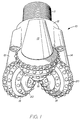
- FIGURE 1 illustrates a drill bit or rock bit, generally indicated by an arrow 10, having a threaded pin section 11 for securing to the bottom end of a drill string.
- the rock bit further includes a main body 12 having a plurality of legs 13, 14 and 15 extending downwardly therefrom. Each leg includes a bearing pin (not shown in FIGURE 1) extending toward the center of the bit.
- Three cone shaped cutters 16 are rotatably mounted on the bearing pins and are adapted to roll along the bottom of a borehole as the bit is rotated.
- the cutters 16 tend to roll along the hole bottom much like a wheel except that because the axes of the bearing pins are offset from the axis of the bit, and because of the geometry of the cones, a true roll of the cones is not possible. Therefore, in addition to the rolling motion, a small sliding motion is imparted thereto which would be analogous to the movement of an automobile tire that is out of alignment.
- Each cutter cone 16 has a plurality of wear resistant inserts 20 interferingly secured by the insert grip 90 in mating holes drilled in the support surface of the cutter cone.
- the inserts 20 are constructed from sintered tungsten carbide.
- the inserts 20 are located in rows that extend circumferentially around the generally conical surface of each cutter. Certain of the rows are arranged to intermesh with other rows of the other cutters so that the entire bottom of the hole is drilled.
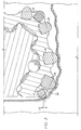
- each cutter is generally conically shaped with a nose area 21 at the apex of the cone and a heel surface 22 at the base of the cone.
- the heel surface 22 is frustoconical and is adapted to pass near the wall of the borehole as the cutters rotate about the borehole bottom.
- the row of inserts 20 closest to the heel surface 22 is called the gage row 23.
- the gage row inserts are further separated into a first row of gage inserts 24 and a second row of heel inserts 25.
- each of the gage inserts 24 is oriented with its axis extending radially outwardly and downwardly to engage the borehole bottom.
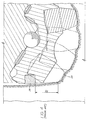
- the cutting profiles of the inserts are illustrated in a cross section as seen in FIGURE 3.
- Each of the heel inserts 25, on the other hand, is with its axis oriented outwardly and downwardly at a greater angle from the centerline of the cone.
- the heel inserts are oriented at an acute angle to the gage inserts in a direction away from the apex of the cutter cone to more closely face the sidewall of the borehole.
- the inserts 20 must be made of an extremely tough grade of tungsten carbide.
- gage row of inserts 24 also contact the hole bottom in a similar matter. However, prior to the present invention, these inserts 24 also performed a scraping action along the borehole sidewall before they make their imprint on the borehole bottom (see FIGURE 4). As mentioned previously, this necessitated making the gage row inserts harder to accommodate the scraping function and minimize wear which can cause the hole to be drilled under the desired gage or diameter. Unfortunately, when one makes a tungsten carbide insert harder, it necessarily becomes less tough.
- the present invention minimizes such a problem by having the heel row inserts 25 interleaved between the the gage inserts with their cutting surface profiles being overlapped.
- the crowns of the gage row inserts and heel row inserts are separated by only a distance D1 in the cutting surface profile as illustrated in FIGURE 3. This enables the heel inserts 25 to engage the borehole sidewall at points much lower in the borehole and much sooner in the cutting cycle than previous heel inserts.
- the distance D1 is preferably within four millimeters in a 20 cm diameter rock bit.
- the crown of the insert is the part of the projected area of the insert that contacts the intact rock formation, as illustrated in FIGURE 3.
- the insert is a gage insert
- the same planetary motion occurs except that the planetary orbit is the largest.
- the same type of movement is involved, i.e. the insert rolls over the spot with a small sliding motion.
- the gage insert would also contact a portion of the sidewall during a portion of its travel. This, of cource, results in almost pure scraping, and the gage insert normally would have to be harder than an inner row insert because of the large abrasive forces acting thereon.
- each alternate gage row insert 24 oriented toward the hole bottom to cut the hole bottom while the other of each alternate heel row insert 25 being oriented to the sidewall to cut the sidewall.
- the first set can be made of a hard material and the second set of a tough material.
- this is accomplished by two means, i.e. the orientation of the two inserts (one toward the hole bottom and the other toward the hole bottom and the other toward the sidewall) and the close proximity of the insert projection profiles.
- the closeness is shown by dimension D1 in Figure 3, which is preferably less than four millimeters.
- the heel row inserts 25 are restricted to mostly scraping, they can be made of a very hard tungsten carbide or they can also be coated with super hard abrasives such as polycrystalline diamond.
- inserts 24 are shown as hemispherical, they can also be constructed of different conventional shapes such as chisels.
- the heel row inserts 25 can have their abrasive surfaces be slightly spherical, flat, or some other configuration and still come within the invention.
Abstract
Description
- The present invention relates generally to earth boring drill bits having rotatable rolling cutters mounted thereon, and more specifically to the positioning of wear resistant inserts located on the gage rows of the cutters.
- Earth boring rock bits for drilling oil and gas wells typically have three rotatable cutters that roll over the bottom of a borehole as the bit rotates. Each cutter is generally conical and has a frustoconical heel surface that passes near the borehole sidewall as the cutter rotates. One type of rock bit, known as a tungsten carbide insert bit or TCI bit, has wear resistant inserts secured in holes formed in the cutters. Such inserts are usually made of tungsten carbide.
- For each cutter, the inserts are arranged in circumferential rows on the conical surface of the rotatable cutter at various distances from the heel surface. The row nearest, but not on the heel surface is known as the gage row. The gage row of inserts cuts rock at the gage of the hole. The heel surface extends upwardly along the wall of the hole drilled by the gage row.
- In some types of bits, such as shown in U.S. Patent No. 3,727,705, certain cutters have gage row structure that includes staggered rows located thereon. The staggered rows comprise two rows of inserts alternately spaced so that the grip portion of the inserts do not interfere. See also U.S. Patent No. 4,343,372.
- In other prior art bits (see FIGURE 4), the inserts on the gage row are oriented in such a manner to cause the cutting elements to cut both the borehole bottom and sidewall. This combined cutting action compromises the insert because the cutting action operating on the borehole bottom is usually a crushing and gouging action while the cutting action operating on the sidewall is a scraping action. Ideally, the crushing action calls for a tough insert while the scraping action calls for a hard insert. As a result, one grade of tungsten carbide cannot ideally perform both functions.
- Other types of bits obviated this problem by having one of the rows of inserts, the one mounted on the heel surface, basically contact the sidewall while the gage row of inserts contacts the borehole bottom. However, it has been found that these rows are separated by such a distance as not to allow optimization of each.
- U.S. Patent Nos. 2,774,570 and 2,774,571 show such arrangements. In each instance, the heel row of inserts is still physically compromised because the lower portion of each insert must still engage the borehole bottom while only the outside portion scrapes the sidewall. In addition, because the heel row is separated from the gage row, there is still a large portion of the sidewall that the gage row must scrape against as it passes through the hole bottom and continues up the sidewall.
- As a result, the inserts of the heel rows of these prior art bits cannot be as hard as that recommended for the sidewall scraping action because they must be tough enough to crush the bottom hole formation. In like manner, the gage row of inserts cannot be as tough as the interior rows of inserts because they must perform a large portion of scraping action on the borehole sidewall.
- The present invention minimizes the above-mentioned shortcomings by providing a rolling cone rock bit with a plurality of cutters each mounted on the body of the bit to rotate about an axis. Each cutter has a generally frusto-conical support surface for rolling contact with the bottom of a borehole, and a heel surface at the base of the cutter adjacent to the sidewall of the borehole. A plurality of wear resistant inserts positioned on the support surface are arranged in circumferential rows, each insert being generally cylindrical with a projected crown area profile and having a central axis. One of the rows of inserts next to the heel surface is a row of gage inserts, with each gage insert being oriented to have its axis extend partiallly radially outward to enable the gage insert to engage the borehole bottom. Each gage insert defines a cutting surface projected crown area profile taken through a section through the centerline of the cone. A plurality of heel inserts located near the gage inserts are at an acute angle with respect to the gage inserts in a direction away from the apex of the cone. Each insert defines a cutting surface projected crown area profile taken through a section through the centerline of the cone. The crown area profile of a heel insert, when rotated around the cone to the same plane as a gage insert crown area profile, overlaps the gage insert crown area profile to enable the heel inserts to slidably engage the borehole sidewall.
- Since the heel row inserts scrape against the wall, they are made of a harder grade of tungsten carbide than the gage row inserts, and the gage row inserts are tougher than the heel row inserts. Preferably, the heel row insert crown area profiles are located up the borehole sidewall within three millimeters of the gage row insert crown area profiles.
- The above noted features and advantages of the present invention will be more fully understood upon a study of the following description in conjunction with the detailed drawings wherein:
- FIGURE 1 is a perspective view of a three cone rock bit utilizing gage row cutters made in accordance with the present invention;
- FIGURE 2 is an enlarged perspective view of one of the cones shown in FIGURE 1;
- FIGURE 3 is a fragmentary sectional view of the cone through the centerline of the cone located in a borehole; and
- FIGURE 4 is a fragmentary sectional view of a prior art cone showing the location of a conventional heel row insert.
- FIGURE 1 illustrates a drill bit or rock bit, generally indicated by an arrow 10, having a threaded
pin section 11 for securing to the bottom end of a drill string. The rock bit further includes amain body 12 having a plurality oflegs cutters 16 are rotatably mounted on the bearing pins and are adapted to roll along the bottom of a borehole as the bit is rotated. - The
cutters 16 tend to roll along the hole bottom much like a wheel except that because the axes of the bearing pins are offset from the axis of the bit, and because of the geometry of the cones, a true roll of the cones is not possible. Therefore, in addition to the rolling motion, a small sliding motion is imparted thereto which would be analogous to the movement of an automobile tire that is out of alignment. - Each
cutter cone 16 has a plurality of wearresistant inserts 20 interferingly secured by theinsert grip 90 in mating holes drilled in the support surface of the cutter cone. Preferably theinserts 20 are constructed from sintered tungsten carbide. - The
inserts 20 are located in rows that extend circumferentially around the generally conical surface of each cutter. Certain of the rows are arranged to intermesh with other rows of the other cutters so that the entire bottom of the hole is drilled. - Referring now to FIGURE 2, as mentioned previously, each cutter is generally conically shaped with a
nose area 21 at the apex of the cone and aheel surface 22 at the base of the cone. Theheel surface 22 is frustoconical and is adapted to pass near the wall of the borehole as the cutters rotate about the borehole bottom. The row ofinserts 20 closest to theheel surface 22 is called thegage row 23. In practice of this invention, the gage row inserts are further separated into a first row ofgage inserts 24 and a second row ofheel inserts 25. - As shown in FIGURE 3, which is a fragmentary cross section through the centerline of a
cutter 16, each of thegage inserts 24 is oriented with its axis extending radially outwardly and downwardly to engage the borehole bottom. The cutting profiles of the inserts are illustrated in a cross section as seen in FIGURE 3. Each of theheel inserts 25, on the other hand, is with its axis oriented outwardly and downwardly at a greater angle from the centerline of the cone. The heel inserts are oriented at an acute angle to the gage inserts in a direction away from the apex of the cutter cone to more closely face the sidewall of the borehole. - During drilling operations, a tremendous amount of weight from the drill string is applied to the bit 10 as it is rotated. As the
inserts 20 of the first three rows, beginning with the nose row, rotated with the cutter, they eventually come in contact with the rock formation on the bottom of the hole. The imprint made on the formation is created by the insert contacting the formation with its trailing side, rolling on the formation about its apex, and then exiting with the last contact being made by its leading side. During this rolling movement, the offset of the cone axis causes eachinsert 20 to slide a small amount which causes the imprint to become somewhat elongated. This combined rolling and sliding motion along with extreme loads involved causes the formation contacted by the insert to be crushed, with little chips being broken off thereby. - Because of the high loads involved with this crushing action, the
inserts 20 must be made of an extremely tough grade of tungsten carbide. - The gage row of
inserts 24 also contact the hole bottom in a similar matter. However, prior to the present invention, theseinserts 24 also performed a scraping action along the borehole sidewall before they make their imprint on the borehole bottom (see FIGURE 4). As mentioned previously, this necessitated making the gage row inserts harder to accommodate the scraping function and minimize wear which can cause the hole to be drilled under the desired gage or diameter. Unfortunately, when one makes a tungsten carbide insert harder, it necessarily becomes less tough. - Because of these compromises, the gage rows of inserts in prior art rock bits suffered from breakage problems. As a result, inserts 26 had to be placed on the heel surfaces of the cones to ensure the heel surface integrity after the gage inserts broke or wore down. Since such inserts were separated a relatively large distance D₂ from the gage inserts (FIGURE 4), they do not come into play and do not contact the sidewall until after the gage inserts break or wear to a certain point, the problems concerning gage insert breakage continued.
- The present invention minimizes such a problem by having the heel row inserts 25 interleaved between the the gage inserts with their cutting surface profiles being overlapped. The crowns of the gage row inserts and heel row inserts are separated by only a distance D₁ in the cutting surface profile as illustrated in FIGURE 3. This enables the heel inserts 25 to engage the borehole sidewall at points much lower in the borehole and much sooner in the cutting cycle than previous heel inserts. The distance D₁ is preferably within four millimeters in a 20 cm diameter rock bit.
- The crown of the insert is the part of the projected area of the insert that contacts the intact rock formation, as illustrated in FIGURE 3. By scraping away the borehole sidewall in those lower areas before the gage inserts have the opportunity to engage the sidewall, the gage inserts 24 are spared from having to do a large amount of scraping. As a result, there would is a much smaller amount of gage insert scraping compared to the prior art, and this amount does not require the gage inserts to make any compromises from a toughness standpoint. Since the vast majority of the cutting action of the gage inserts is the crushing and gouging action occurring on the borehole bottom, the gage row inserts 24 can now be made of the same tough grade of tungsten carbide as the inner rows of inserts.
- If one were to isolate attention on a single cutting insert as the bit rotates within a borehole, its path would be seen to be a modified planetary motion. The cutter cone rotates about the journal which is slightly offset from the axis of the bit. As the bit rotates, the cone rolls on the borehole bottom with a small sliding motion imparted thereto because of the geometry of the cones and the journal offset. During this motion, the insert eventually moves down into engagement with the borehole bottom. As it touches down on a particular location, the insert rotates on that spot but with a small sliding motion. For the most part, the insert acts on the formation spot in a crushing action in addition to a small scraping action. As a result, such inserts have to be tough to resist the comprehensive forces acting on the insert. This greatly overrides the need to be hard to resist the small abrasive forces acting on the insert because of the small sliding.
- If the insert is a gage insert, the same planetary motion occurs except that the planetary orbit is the largest. As the gage insert touches down on the hole bottom, the same type of movement is involved, i.e. the insert rolls over the spot with a small sliding motion. However, because of the journal offset, the gage insert would also contact a portion of the sidewall during a portion of its travel. This, of cource, results in almost pure scraping, and the gage insert normally would have to be harder than an inner row insert because of the large abrasive forces acting thereon.
- As a result, conventional gage inserts had the problem of having to resist the high compressive forces encountered with the hole bottom, and the high abrasive forces encountered with the sidewall of the borehole. Unfortunately, compromises had to be made because tungsten carbide inserts cannot have a maximum toughness and maximum hardness at the same time. Because of this, the gage inserts usually always wore faster than the inner rows of inserts.
- Prior bits sometimes avoid any sliding motion because of the true roll aspects of the cone, i.e. zero journal offset and zero oversize angle. However, this was not always the case, even for hard formation bits. Usually for such bits, only one row of inserts would become the "drive row" and assumed the true roll condition. All other rows would have some sliding associated with them. Therefore, unless the outer gage row would become the drive row, a certain amount of sliding would occur and the sliding forces acting on the sidewall would have to be dealt with.
- In today's drilling, the vast majority of rock bits are soft and medium formation bits that have journal offset and do not have any "true roll" capabilities.
- In this invention, to optimize drilling with a bit having offset and no true rolling, there is a single substantially overlapping row of inserts near the heel of the cutter cone with each alternate gage row insert 24 oriented toward the hole bottom to cut the hole bottom while the other of each alternate heel row insert 25 being oriented to the sidewall to cut the sidewall.
- Since sidewall scraping is going to exist a set of heel row inserts is oriented to do substantially all of the scraping and leave very little scraping for the other set of gage row inserts which are left to attack the hole bottom. As a result, the first set can be made of a hard material and the second set of a tough material.
- Basically, this is accomplished by two means, i.e. the orientation of the two inserts (one toward the hole bottom and the other toward the hole bottom and the other toward the sidewall) and the close proximity of the insert projection profiles. The closeness is shown by dimension D¹ in Figure 3, which is preferably less than four millimeters.
- Moreover, since the heel row inserts 25 are restricted to mostly scraping, they can be made of a very hard tungsten carbide or they can also be coated with super hard abrasives such as polycrystalline diamond.
- Although the
inserts 24 are shown as hemispherical, they can also be constructed of different conventional shapes such as chisels. In addition, the heel row inserts 25 can have their abrasive surfaces be slightly spherical, flat, or some other configuration and still come within the invention. - It will of course be realized that various other modifications can be made in the design and operation of the present invention without departing from the spirit thereof. Thus, while the principal preferred construction and mode of operation of the invention have been illustrated and described in what is now considered to represent its best embodiments, it should be understood that within the scope of the appended claims, the invention may be practiced otherwise than as specifically described and illustrated.
Claims (9)
- A rock bit for drilling a borehole, having a bit body, a plurality of cutters each mounted on the bit body to rotate about an axis, each cutter having a generally frusto-conical support surface for rolling contact with the bottom of a borehole, each cutter further having a heel surface at the base thereof adjacent to the sidewall of the borehole, and a plurality of wear resistant inserts positioned on the support surface and being arranged in circumferential rows, each insert being generally cylindrical with a projected crown area profile and having a central axis, one of the rows of inserts being positioned next to the heel surface defining a row of gage inserts, with each gage insert oriented to have its axis extend partially radially outward to enable the gage insert to engage the borehole bottom, each gage insert further defining a cutting surface projected crown area profile taken through a section through the centerline of the cone, and characterized by:
a plurality of heel inserts located near the gage inserts at an acute angle with respect to the gage inserts in a direction away from the apex of the cone, each heel insert further defining a cutting surface projected crown area profile taken through a section through the centerline of the cone, the crown area profile of the heel insert, when rotated around the cone to the same plane as a gage insert crown area profile, overlapping the gage insert crown area profile to enable the heel inserts to slidably engage the borehole sidewall. - The rock bit of Claim 1 wherein the heel inserts are interleaved between the gage inserts.
- The rock bit of any of the preceding claims wherein the inserts are made of tungsten carbide.
- The rock bit of claim 3 wherein the heel row inserts are made of a harder grade of tungsten carbide than the gage row inserts.
- The rock bit of claim 4 wherein the gage row inserts are made of the same tough grade of tungsten carbide as the other rows of inserts.
- The rock bit of any of the preceding claims wherein the heel row insert crown area profiles are located up the borehole sidewall within four millimeters of the gage row insert crown area profiles.
- The rock bit of any of the preceding claims wherein the heel inserts are coated with an outer layer of polycrystalline diamond.
- The rock bit of any of the preceding claims wherein the rotational axes of the cutters are each offset from the axis of the bit body.
- The rock bit of any of the preceding claims wherein the cutters, when rotating, define a substantially flat surface corresponding to the bottom of a borehole, and a generally cylindrical surface corresponding to the side wall of a borehole.
Applications Claiming Priority (2)
| Application Number | Priority Date | Filing Date | Title |
|---|---|---|---|
| US69390091A | 1991-05-01 | 1991-05-01 | |
| US693900 | 1991-05-01 |
Publications (3)
| Publication Number | Publication Date |
|---|---|
| EP0511547A2 true EP0511547A2 (en) | 1992-11-04 |
| EP0511547A3 EP0511547A3 (en) | 1993-04-14 |
| EP0511547B1 EP0511547B1 (en) | 1996-12-11 |
Family
ID=24786590
Family Applications (1)
| Application Number | Title | Priority Date | Filing Date |
|---|---|---|---|
| EP92106450A Expired - Lifetime EP0511547B1 (en) | 1991-05-01 | 1992-04-14 | Rock bit |
Country Status (5)
| Country | Link |
|---|---|
| EP (1) | EP0511547B1 (en) |
| CA (1) | CA2066296A1 (en) |
| DE (1) | DE69215746D1 (en) |
| MX (1) | MX9201958A (en) |
| NO (1) | NO921667L (en) |
Cited By (16)
| Publication number | Priority date | Publication date | Assignee | Title |
|---|---|---|---|---|
| GB2273726A (en) * | 1992-12-17 | 1994-06-29 | Baker Hughes Inc | Earth boring bit |
| GB2274129A (en) * | 1993-01-08 | 1994-07-13 | Smith International | Rotary cone rock bit with ultra hard heel row inserts |
| EP0633387A2 (en) * | 1993-07-08 | 1995-01-11 | Baker Hughes Incorporated | Earth-boring bit with improved cutting structure |
| EP0723066A2 (en) * | 1995-01-17 | 1996-07-24 | Baker Hughes Incorporated | Earth-boring bit with improved cutting structure |
| US5589443A (en) * | 1995-12-21 | 1996-12-31 | Smith International, Inc. | Rock bit grease composition |
| US5668092A (en) * | 1993-04-07 | 1997-09-16 | Smith International, Inc. | Rock bit grease composition |
| US5819861A (en) * | 1993-07-08 | 1998-10-13 | Baker Hughes Incorporated | Earth-boring bit with improved cutting structure |
| GB2363143A (en) * | 2000-06-08 | 2001-12-12 | Smith International | Cutting structure for roller cone drill bits |
| US6651758B2 (en) * | 2000-05-18 | 2003-11-25 | Smith International, Inc. | Rolling cone bit with elements fanned along the gage curve |
| US6918455B2 (en) | 1997-06-30 | 2005-07-19 | Smith International | Drill bit with large inserts |
| US6986395B2 (en) | 1998-08-31 | 2006-01-17 | Halliburton Energy Services, Inc. | Force-balanced roller-cone bits, systems, drilling methods, and design methods |
| US7729895B2 (en) | 2005-08-08 | 2010-06-01 | Halliburton Energy Services, Inc. | Methods and systems for designing and/or selecting drilling equipment with desired drill bit steerability |
| US7860696B2 (en) | 2005-08-08 | 2010-12-28 | Halliburton Energy Services, Inc. | Methods and systems to predict rotary drill bit walk and to design rotary drill bits and other downhole tools |
| US7860693B2 (en) | 2005-08-08 | 2010-12-28 | Halliburton Energy Services, Inc. | Methods and systems for designing and/or selecting drilling equipment using predictions of rotary drill bit walk |
| RU2473770C1 (en) * | 2011-10-05 | 2013-01-27 | Дмитрий Юрьевич Сериков | Drilling rock bit |
| US9493990B2 (en) | 2004-03-02 | 2016-11-15 | Halliburton Energy Services, Inc. | Roller cone drill bits with optimized bearing structures |
Citations (3)
| Publication number | Priority date | Publication date | Assignee | Title |
|---|---|---|---|---|
| US2990025A (en) * | 1958-06-16 | 1961-06-27 | Dresser Ind | Bit |
| FR2029550A1 (en) * | 1969-01-28 | 1970-10-23 | Dresser Ind | |
| US3727705A (en) * | 1972-01-21 | 1973-04-17 | Hughes Tool Co | Drill bit with improved gage compact arrangement |
-
1992
- 1992-04-14 EP EP92106450A patent/EP0511547B1/en not_active Expired - Lifetime
- 1992-04-14 DE DE69215746T patent/DE69215746D1/en not_active Expired - Lifetime
- 1992-04-16 CA CA002066296A patent/CA2066296A1/en not_active Abandoned
- 1992-04-28 MX MX9201958A patent/MX9201958A/en unknown
- 1992-04-29 NO NO92921667A patent/NO921667L/en unknown
Patent Citations (3)
| Publication number | Priority date | Publication date | Assignee | Title |
|---|---|---|---|---|
| US2990025A (en) * | 1958-06-16 | 1961-06-27 | Dresser Ind | Bit |
| FR2029550A1 (en) * | 1969-01-28 | 1970-10-23 | Dresser Ind | |
| US3727705A (en) * | 1972-01-21 | 1973-04-17 | Hughes Tool Co | Drill bit with improved gage compact arrangement |
Cited By (29)
| Publication number | Priority date | Publication date | Assignee | Title |
|---|---|---|---|---|
| GB2273726A (en) * | 1992-12-17 | 1994-06-29 | Baker Hughes Inc | Earth boring bit |
| GB2273726B (en) * | 1992-12-17 | 1996-04-24 | Baker Hughes Inc | Earth boring kit |
| GB2274129B (en) * | 1993-01-08 | 1996-08-07 | Smith International | Rotary cone rock bit with ultra hard heel row inserts |
| GB2274129A (en) * | 1993-01-08 | 1994-07-13 | Smith International | Rotary cone rock bit with ultra hard heel row inserts |
| US5668092A (en) * | 1993-04-07 | 1997-09-16 | Smith International, Inc. | Rock bit grease composition |
| US5542485A (en) * | 1993-07-08 | 1996-08-06 | Baker Hughes Incorporated | Earth-boring bit with improved cutting structure |
| EP0633387A3 (en) * | 1993-07-08 | 1995-07-26 | Baker Hughes Inc | Earth-boring bit with improved cutting structure. |
| US5819861A (en) * | 1993-07-08 | 1998-10-13 | Baker Hughes Incorporated | Earth-boring bit with improved cutting structure |
| EP0633387A2 (en) * | 1993-07-08 | 1995-01-11 | Baker Hughes Incorporated | Earth-boring bit with improved cutting structure |
| EP0723066A2 (en) * | 1995-01-17 | 1996-07-24 | Baker Hughes Incorporated | Earth-boring bit with improved cutting structure |
| EP0723066A3 (en) * | 1995-01-17 | 1997-08-20 | Baker Hughes Inc | Earth-boring bit with improved cutting structure |
| US5589443A (en) * | 1995-12-21 | 1996-12-31 | Smith International, Inc. | Rock bit grease composition |
| US6918455B2 (en) | 1997-06-30 | 2005-07-19 | Smith International | Drill bit with large inserts |
| US6986395B2 (en) | 1998-08-31 | 2006-01-17 | Halliburton Energy Services, Inc. | Force-balanced roller-cone bits, systems, drilling methods, and design methods |
| US6651758B2 (en) * | 2000-05-18 | 2003-11-25 | Smith International, Inc. | Rolling cone bit with elements fanned along the gage curve |
| GB2363143B (en) * | 2000-06-08 | 2002-08-14 | Smith International | Cutting structure for roller cone drill bits |
| US6374930B1 (en) | 2000-06-08 | 2002-04-23 | Smith International, Inc. | Cutting structure for roller cone drill bits |
| GB2363143A (en) * | 2000-06-08 | 2001-12-12 | Smith International | Cutting structure for roller cone drill bits |
| US9493990B2 (en) | 2004-03-02 | 2016-11-15 | Halliburton Energy Services, Inc. | Roller cone drill bits with optimized bearing structures |
| US7860693B2 (en) | 2005-08-08 | 2010-12-28 | Halliburton Energy Services, Inc. | Methods and systems for designing and/or selecting drilling equipment using predictions of rotary drill bit walk |
| US7827014B2 (en) | 2005-08-08 | 2010-11-02 | Halliburton Energy Services, Inc. | Methods and systems for design and/or selection of drilling equipment based on wellbore drilling simulations |
| US7860696B2 (en) | 2005-08-08 | 2010-12-28 | Halliburton Energy Services, Inc. | Methods and systems to predict rotary drill bit walk and to design rotary drill bits and other downhole tools |
| US7778777B2 (en) | 2005-08-08 | 2010-08-17 | Halliburton Energy Services, Inc. | Methods and systems for designing and/or selecting drilling equipment using predictions of rotary drill bit walk |
| US8145465B2 (en) | 2005-08-08 | 2012-03-27 | Halliburton Energy Services, Inc. | Methods and systems to predict rotary drill bit walk and to design rotary drill bits and other downhole tools |
| US8296115B2 (en) | 2005-08-08 | 2012-10-23 | Halliburton Energy Services, Inc. | Methods and systems for designing and/or selecting drilling equipment using predictions of rotary drill bit walk |
| US8352221B2 (en) | 2005-08-08 | 2013-01-08 | Halliburton Energy Services, Inc. | Methods and systems for design and/or selection of drilling equipment based on wellbore drilling simulations |
| US8606552B2 (en) | 2005-08-08 | 2013-12-10 | Halliburton Energy Services, Inc. | Methods and systems for designing and/or selecting drilling equipment using predictions of rotary drill bit walk |
| US7729895B2 (en) | 2005-08-08 | 2010-06-01 | Halliburton Energy Services, Inc. | Methods and systems for designing and/or selecting drilling equipment with desired drill bit steerability |
| RU2473770C1 (en) * | 2011-10-05 | 2013-01-27 | Дмитрий Юрьевич Сериков | Drilling rock bit |
Also Published As
| Publication number | Publication date |
|---|---|
| EP0511547A3 (en) | 1993-04-14 |
| CA2066296A1 (en) | 1992-11-02 |
| NO921667L (en) | 1992-11-02 |
| DE69215746D1 (en) | 1997-01-23 |
| MX9201958A (en) | 1992-11-01 |
| NO921667D0 (en) | 1992-04-29 |
| EP0511547B1 (en) | 1996-12-11 |
Similar Documents
| Publication | Publication Date | Title |
|---|---|---|
| US5353885A (en) | Rock bit | |
| CA2220679C (en) | Rolling cone bit with gage and off-gage cutter elements positioned to separate sidewall and bottom hole cutting duty | |
| CA2288923C (en) | High offset bits with super-abrasive cutters | |
| EP0511547B1 (en) | Rock bit | |
| US6439326B1 (en) | Centered-leg roller cone drill bit | |
| CA2113054C (en) | Ultra hard insert cutters for heel row rotary cone rock bit applications | |
| US5813485A (en) | Cutter element adapted to withstand tensile stress | |
| US7686106B2 (en) | Rock bit and inserts with wear relief grooves | |
| US6651758B2 (en) | Rolling cone bit with elements fanned along the gage curve | |
| US20080060852A1 (en) | Gage configurations for drill bits | |
| AU2725997A (en) | Rolling cone bit with enhancements in cutter element placement and materials to optimize borehole corner cutting duty | |
| CA2257934C (en) | Cutter element adapted to withstand tensile stress | |
| CA1046497A (en) | Rotary rock bit with multiple row coverage for very hard formations | |
| CA2257885C (en) | Non-symmetrical stress-resistant rotary drill bit cutter element | |
| GB2349405A (en) | Rolling cone bit | |
| GB2378725A (en) | A roller cone drill bit for hard formations having a high offset | |
| GB2373275A (en) | Roller cone drill bit |
Legal Events
| Date | Code | Title | Description |
|---|---|---|---|
| PUAI | Public reference made under article 153(3) epc to a published international application that has entered the european phase |
Free format text: ORIGINAL CODE: 0009012 |
|
| AK | Designated contracting states |
Kind code of ref document: A2 Designated state(s): DE FR GB IT NL |
|
| PUAL | Search report despatched |
Free format text: ORIGINAL CODE: 0009013 |
|
| AK | Designated contracting states |
Kind code of ref document: A3 Designated state(s): DE FR GB IT NL |
|
| 17P | Request for examination filed |
Effective date: 19931008 |
|
| 17Q | First examination report despatched |
Effective date: 19950118 |
|
| GRAG | Despatch of communication of intention to grant |
Free format text: ORIGINAL CODE: EPIDOS AGRA |
|
| GRAH | Despatch of communication of intention to grant a patent |
Free format text: ORIGINAL CODE: EPIDOS IGRA |
|
| GRAH | Despatch of communication of intention to grant a patent |
Free format text: ORIGINAL CODE: EPIDOS IGRA |
|
| GRAA | (expected) grant |
Free format text: ORIGINAL CODE: 0009210 |
|
| AK | Designated contracting states |
Kind code of ref document: B1 Designated state(s): DE FR GB IT NL |
|
| PG25 | Lapsed in a contracting state [announced via postgrant information from national office to epo] |
Ref country code: IT Free format text: LAPSE BECAUSE OF FAILURE TO SUBMIT A TRANSLATION OF THE DESCRIPTION OR TO PAY THE FEE WITHIN THE PRE;WARNING: LAPSES OF ITALIAN PATENTS WITH EFFECTIVE DATE BEFORE 2007 MAY HAVE OCCURRED AT ANY TIME BEFORE 2007. THE CORRECT EFFECTIVE DATE MAY BE DIFFERENT FROM THE ONE RECORDED.SCRIBED TIME-LIMIT Effective date: 19961211 Ref country code: FR Effective date: 19961211 Ref country code: NL Free format text: LAPSE BECAUSE OF FAILURE TO SUBMIT A TRANSLATION OF THE DESCRIPTION OR TO PAY THE FEE WITHIN THE PRESCRIBED TIME-LIMIT Effective date: 19961211 |
|
| REF | Corresponds to: |
Ref document number: 69215746 Country of ref document: DE Date of ref document: 19970123 |
|
| PG25 | Lapsed in a contracting state [announced via postgrant information from national office to epo] |
Ref country code: DE Effective date: 19970312 |
|
| NLV1 | Nl: lapsed or annulled due to failure to fulfill the requirements of art. 29p and 29m of the patents act | ||
| EN | Fr: translation not filed | ||
| PLBE | No opposition filed within time limit |
Free format text: ORIGINAL CODE: 0009261 |
|
| STAA | Information on the status of an ep patent application or granted ep patent |
Free format text: STATUS: NO OPPOSITION FILED WITHIN TIME LIMIT |
|
| 26N | No opposition filed | ||
| PGFP | Annual fee paid to national office [announced via postgrant information from national office to epo] |
Ref country code: GB Payment date: 19990318 Year of fee payment: 8 |
|
| PG25 | Lapsed in a contracting state [announced via postgrant information from national office to epo] |
Ref country code: GB Free format text: LAPSE BECAUSE OF NON-PAYMENT OF DUE FEES Effective date: 20000414 |
|
| GBPC | Gb: european patent ceased through non-payment of renewal fee |
Effective date: 20000414 |