EP0514343A2 - Automatic lateral guidance control system - Google Patents
Automatic lateral guidance control system Download PDFInfo
- Publication number
- EP0514343A2 EP0514343A2 EP92810363A EP92810363A EP0514343A2 EP 0514343 A2 EP0514343 A2 EP 0514343A2 EP 92810363 A EP92810363 A EP 92810363A EP 92810363 A EP92810363 A EP 92810363A EP 0514343 A2 EP0514343 A2 EP 0514343A2
- Authority
- EP
- European Patent Office
- Prior art keywords
- vehicle
- distance
- marker
- path
- markers
- Prior art date
- Legal status (The legal status is an assumption and is not a legal conclusion. Google has not performed a legal analysis and makes no representation as to the accuracy of the status listed.)
- Granted
Links
- 239000003550 marker Substances 0.000 claims description 112
- 238000012552 review Methods 0.000 claims description 34
- 230000006870 function Effects 0.000 claims description 31
- 238000000034 method Methods 0.000 claims description 27
- 230000003287 optical effect Effects 0.000 claims description 7
- 230000004044 response Effects 0.000 claims description 5
- 238000005259 measurement Methods 0.000 description 20
- 238000010586 diagram Methods 0.000 description 8
- 230000001939 inductive effect Effects 0.000 description 8
- 230000035484 reaction time Effects 0.000 description 8
- 230000008569 process Effects 0.000 description 6
- 238000013528 artificial neural network Methods 0.000 description 3
- 230000008901 benefit Effects 0.000 description 3
- 238000004364 calculation method Methods 0.000 description 3
- 230000001965 increasing effect Effects 0.000 description 3
- 239000000463 material Substances 0.000 description 3
- 238000013461 design Methods 0.000 description 2
- 238000012423 maintenance Methods 0.000 description 2
- 230000035945 sensitivity Effects 0.000 description 2
- 230000008859 change Effects 0.000 description 1
- 238000006243 chemical reaction Methods 0.000 description 1
- 238000007796 conventional method Methods 0.000 description 1
- 125000004122 cyclic group Chemical group 0.000 description 1
- 238000001514 detection method Methods 0.000 description 1
- 238000006073 displacement reaction Methods 0.000 description 1
- 238000005516 engineering process Methods 0.000 description 1
- 239000012770 industrial material Substances 0.000 description 1
- 238000009434 installation Methods 0.000 description 1
- 238000012804 iterative process Methods 0.000 description 1
- 238000012886 linear function Methods 0.000 description 1
- 238000005007 materials handling Methods 0.000 description 1
- 230000003340 mental effect Effects 0.000 description 1
- 238000012986 modification Methods 0.000 description 1
- 230000004048 modification Effects 0.000 description 1
- 230000037361 pathway Effects 0.000 description 1
- 238000012545 processing Methods 0.000 description 1
- 239000004065 semiconductor Substances 0.000 description 1
- 230000003068 static effect Effects 0.000 description 1
- 238000012546 transfer Methods 0.000 description 1
Images


Classifications
-
- B—PERFORMING OPERATIONS; TRANSPORTING
- B62—LAND VEHICLES FOR TRAVELLING OTHERWISE THAN ON RAILS
- B62D—MOTOR VEHICLES; TRAILERS
- B62D1/00—Steering controls, i.e. means for initiating a change of direction of the vehicle
- B62D1/24—Steering controls, i.e. means for initiating a change of direction of the vehicle not vehicle-mounted
- B62D1/28—Steering controls, i.e. means for initiating a change of direction of the vehicle not vehicle-mounted non-mechanical, e.g. following a line or other known markers
-
- G—PHYSICS
- G01—MEASURING; TESTING
- G01S—RADIO DIRECTION-FINDING; RADIO NAVIGATION; DETERMINING DISTANCE OR VELOCITY BY USE OF RADIO WAVES; LOCATING OR PRESENCE-DETECTING BY USE OF THE REFLECTION OR RERADIATION OF RADIO WAVES; ANALOGOUS ARRANGEMENTS USING OTHER WAVES
- G01S17/00—Systems using the reflection or reradiation of electromagnetic waves other than radio waves, e.g. lidar systems
- G01S17/88—Lidar systems specially adapted for specific applications
- G01S17/93—Lidar systems specially adapted for specific applications for anti-collision purposes
- G01S17/931—Lidar systems specially adapted for specific applications for anti-collision purposes of land vehicles
-
- G—PHYSICS
- G05—CONTROLLING; REGULATING
- G05D—SYSTEMS FOR CONTROLLING OR REGULATING NON-ELECTRIC VARIABLES
- G05D1/00—Control of position, course or altitude of land, water, air, or space vehicles, e.g. automatic pilot
- G05D1/02—Control of position or course in two dimensions
- G05D1/021—Control of position or course in two dimensions specially adapted to land vehicles
- G05D1/0231—Control of position or course in two dimensions specially adapted to land vehicles using optical position detecting means
- G05D1/0234—Control of position or course in two dimensions specially adapted to land vehicles using optical position detecting means using optical markers or beacons
- G05D1/0236—Control of position or course in two dimensions specially adapted to land vehicles using optical position detecting means using optical markers or beacons in combination with a laser
Definitions
- the present invention generally relates to an automatic lateral guidance control system for controlling the direction of a moving vehicle along a predetermined path, and more particularly, to an improved vehicle controller for use in an automatic lateral guidance control system for controlling the direction of a motor vehicle on a highway.
- So-called "Automated Highways" are presently being contemplated, which will include vehicular-based systems that will automatically control the motor vehicle's speed, steering and braking, in order to substitute for the driver as a prime source of control over the vehicle.
- the expected advantages of such systems will be to improve the overall flow of traffic and increase highway safety.
- the present invention is directed to such a vehicular-based system for automatically controlling vehicle direction, which accurately guides a vehicle along a path while providing a comfortable ride for passengers.
- a variety of conventional guidance systems are used for controlling the movement of vehicles travelling along a predetermined path such as, for example, robotic material handling guidance systems.
- a "robotic vehicle” for moving materials between separate points in a warehouse or storage area without human intervention, is provided with an automated steering control system that utilizes an inductive sensor mounted near the bottom of the vehicle in order to sense a current passing through a thin wire disposed either at or below the surface of a predetermined pathway.
- the inductive sensor senses the magnetic field radiated from the wire and, using conventional phase-detection techniques, produces an output signal which indicates the extent to which the vehicle has drifted laterally from the desired course.
- the output signals from the sensor are provided to a vehicle control circuit that typically converts the sensor's output signal into control error signal which are used to direct the vehicle back on course.
- a series of spaced-apart responders are disposed in a single row parallel to the centerline of the roadway, or in a pair of rows on opposite sides of the centerline, for reflecting radiant energy from the laser transmitter back to the receiver.
- the laser transmitter radiates two overlapping beams which are amplitude-modulated by sine waves that are 180 degrees out of phase.
- the receiver merges the two reflected beams into a single beam that is subject to a cyclic translatory shift in amplitude.
- the amplitude shift is translated into a voltage whose amplitude varies in accordance with the position of the vehicle.
- a comparison of the phase differences between the transmitted and reflected beams provides a determination of the vehicle's location with respect to the reflectors.
- the use of such a system typically requires the use of a high powered laser transmitter, which can have a prohibitively high cost.
- the conventional laser-controlled, automatic guidance systems have limited tracking performance or accuracy with respect to controlling the vehicle's direction, because such systems do not take into account the vehicle's speed.
- the reaction time needed to steer the vehicle in response to sensed changes in the direction of the road increases as the vehicle's speed increases.
- the conventional automatic guidance systems for motor vehicles may be considered "look-ahead" systems, the reaction time for the conventional systems is still limited at the higher vehicle speeds.
- the present invention provides a novel arrangement for a "look-ahead" automatic lateral guidance control system that accounts for the speed of the vehicle and thereby increases the tracking performance and accuracy of the system, while providing a comfortable travelling environment.
- an object of the present invention to provide an improved automatic guidance control system having an arrangement for automatically guiding the direction of a moving vehicle.
- an improved automatic guidance control system for guiding moving vehicles which includes a sensing subsystem for viewing an area in front of a vehicle, a plurality of energy radiating or energy reflective devices disposed adjacent a predetermined length of road, an apparatus for translating the radiated or reflected information from the viewed area into coordinate data representing an approximation of the predetermined path along the road, and a vehicle controller for determining the vehicle's heading with respect to the approximated path and providing an output control signal to correct the vehicles heading with respect to the approximated path.
- the system uses past and present marker and vehicle position data to calculate a predetermined path for the vehicle. GUn factors and human engineering factors are determined to maximize comfort to passengers of the vehicle and to optimize performance of the system.
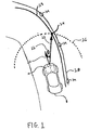
- FIGURE 1 is a schematic diagram of an improved automatic lateral guidance control system in accordance with a preferred embodiment of the present invention.
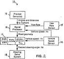
- FIGURE 2 is an overall functional block diagram of the improved automatic lateral guidance control system of FIGURE 1.
- FIGURE 3 illustrates a sequence of steps which may be performed to operate the improved automatic lateral guidance control system of FIGURES 1 and 2.
- FIGURE 4 is a schematic diagram illustrating a set of steps in FIGURE 3 for calculating relative vehicle and marker position measurements.
- FIGURE 5 illustrates a set of steps in FIGURE 3 for calculating past and present relative vehicle and marker position measurements.
- FIGURE 6 illustrates the conversion of the past position measurements as shown in FIGURE 5 from one coordinate system to another.
- FIGURE 7 is a block diagram of an improved automatic lateral guidance control system in accordance with a second embodiment of the present invention.
- FIGURE 8 illustrates the improved automatic lateral guidance control system of FIGURE 7 operating with respect to a predetermined path.
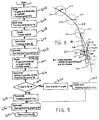
- FIGURE 9 illustrates a sequence of steps which may be performed to operate the improved automatic lateral guidance control system illustrated in FIGURES 7 and 8.
- FIGURE 10 illustrates an improved automatic lateral guidance control system in accordance with a third embodiment of the present invention.
- FIGURE 11 illustrates a sequence of steps which may be performed to operate the improved automatic lateral guidance control system of FIGURE 10.
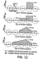
- FIGURE 12 illustrates various gain schedules for use with the automatic lateral guidance control systems of FIGURES 7, 8, 9, 10 and 11.
- FIGURE 13 schematically illustrates a use of a comfort factor in accordance with the present invention.
- FIGURE 14 schematically illustrates a relationship between the comfort factor of FIGURE 13 and the curvature of the road.
- Figure 1 is a schematic diagram of an improved automatic lateral guidance control system in accordance with a preferred embodiment of the present invention.
- Vehicle 8 is equipped with automatic lateral guidance control system 10 which automatically guides the heading or forward direction of vehicle 8 with respect to actual path 28.
- a plurality of reflectors 34 may be disposed adjacent to or along path 28.
- retroflectors which are well known in the art may be utilized for reflectors 34 in a preferred embodiment, the present invention is not intended to be limited thereto, and any suitable optical reflecting medium may be substituted for reflectors 34.
- a series of painted, reflective stripes may be disposed along (i.e., following the length of) path 28.
- Actual path 28 may comprise for example, a roadway, a lane of a highway or any other like predetermined route.
- Vehicle 8 may comprise for example, an automobile, truck, bus, or any other suitable type of mobile vehicle for travelling along a predetermined route such as path 28.
- Automatic lateral guidance control system 10 guides vehicle 8 in a generally forward direction along the forward, centerline axis of vehicle 8, which axis is hereinafter defined as vehicle heading 20.
- Automatic lateral guidance control system 10 adjusts the course of vehicle 8 in order to cause the vehicle to follow path 28.
- automatic lateral guidance control system 10 adjusts the course of vehicle 8 by determining the angular displacement between vehicle heading 20 and a straight line drawn from the front of vehicle 8 to selected target point 24, whereby target point 24 is a point located on ideal road geometry 29.
- ideal road geometry 29 is a calculated approximation of actual path 28.
- Vehicle 8 is then steered with respect to selected target point 24.
- the process of determining the vehicle's heading with respect to a selected target point on ideal road geometry 29, and correcting the vehicle's heading is an iterative process which is per formed by a sequence of steps programmed into a microcomputer. Consequently, the process of determining and correcting the vehicle's heading is continuously repeated as the vehicle travel along the roadway.
- the system illustrated in Figures 1, 2 and 3 is considered to comprise a continuum of target points 24 or "markers" disposed along ideal road geometry 29.
- a continuum of target points 24 or "markers” disposed along ideal road geometry 29.
- Such a system is hereinafter referred to as a “continuous marker system.”
- ideal road geometry 29 is hereinafter defined to be an accurate approximation of the curvature of actual path 28. In essence, road geometry 29 is substantially equivalent to actual path 28.
- a preferred technique for calculating ideal road geometry 29 is discussed in substantive detail below.
- FIG. 2 is an overall functional block diagram of the improved automatic lateral guidance control system of Figure 1.
- Automatic lateral guidance control system 10 comprises vehicle speed sensor 32, preview sensors 16, yaw rate sensor 13, signal processor 14, microcontroller 12, and steering servo system 18.
- Microcontroller 12 comprises a microprocessor, read only memory (ROM), read access memory (RAM), and input/output ports (I/O ports). It should be understood that microcontroller 12 may also comprise any additional circuitry, such as A/D and D/A converters, combinational logic circuitry, latching circuitry, etc., that may be necessary for the operation and interconnection of microcontroller 12 with respect to the components of automatic lateral guidance control system 10. All of the above-described components of microcontroller 12 may be located on an individual semiconductor chip.
- microcontroller 12 may comprise, for example, a Motorola MC68HC705C8 type microcontroller. Alternatively, a Digital Signal Processing Board, such as for example, a Texas Instruments TMS 320C30, may be utilized. Although the structure and operation of a specific type of microcontroller is described herein for illustrative purposes with respect to a preferred embodiment, the type of microcontroller selected is not critical to making and using the present invention, and the present invention is not intended to be limited thereto. Any suitable microcontroller or similarly, constructed apparatus for performing the operations of the present invention may be substituted herein.
- vehicle speed sensor 32 is coupled to microcontroller 12 and to signal processor 14 to provide a measurement of the speed of vehicle 8.
- Vehicle speed sensor 32 may comprise any of a number of conventional speed sensors for use in a motor vehicle such as, for example, a speed sensor connected to a wheel of vehicle 8.
- Preview sensors 16 are coupled to an input of signal processor 14 and provide measurements of the relative position, including distance and angle, of vehicle 8 with respect to at least one of reflectors 34 located along path 28.
- Yaw rate sensor 15 is coupled to an input of the signal processor 14 and provides measurements of the vehicle yaw rate information.
- An output from signal processor 14 is coupled to an input of microcontroller 12.
- signal processor 14 operates to receive position measurements of reflectors 34 relative to the heading of vehicle 8 from preview sensors 16, to receive yaw rate information from yaw rate sensor 15 and to receive speed information from speed sensor 32. Signal processor 14 process this information to calculate ideal road geometry 29 and provide ideal road geometry information to microcontroller 12. Alternatively, microcontroller 12 may calculate road geometry 29 directly from the angle and distance measurements provided by preview sensors 16, speed measurements provided by vehicle speed sensor and yaw rate information provided by yaw rate sensor 15.
- Steering servo system 18 is coupled to microcontroller 12 and may, for example, comprise a conventional steering control system including a steering controller and steering actuator. Steering servo system 18 operates to change the direction of vehicle 8 in response to control signals generated by microcontroller 12, in order to maintain the heading of vehicle 8 with respect to path 28.
- Preview sensors 16, which are electrically coupled to microcontroller 12 and signal processor 14, may be mounted on a right front portion of vehicle 8, for example, for use in a country (such as the United States) where vehicles typically travel on the right hand side of the road. Thus, preview sensors 16 may scan reflectors or other types of road markers disposed at or near the right hand side of the roadway. It is also envisioned that preview sensors 16 may be mounted in the center front portion of vehicle 8, in order to scan both sides of the roadway. Preview sensors 16 may comprise, for example, a laser transmitter/receiver (radar) system or other optical sensing apparatus, such as a video camera.
- radar laser transmitter/receiver
- preview sensors 16 are described herein with respect to an optical sensing apparatus for illustrative purposes only, but the present invention is not intended to be limited thereto.
- Preview sensors 16 also may include other suitable sensing devices for determining angle and distance to each of a series of "markers" disposed adjacent to a roadway such as, for example, a receiver operating at radio-frequencies (RF) that detects and processes radiated signal from a series of RF "beacon” transmitters disposed adjacent to the road, or any other suitable sensing apparatus for sensing the distance and angle with respect to vehicle 8 and each of a series of energy reflecting or energy radiating "markers”.
- RF radio-frequencies
- the term “reflector” refers to any reflective medium for reflecting light energy.
- the term “marker” more broadly may refer either to an energy reflecting device or energy radiating device disposed adjacent to a roadway.
- the term “marker” may also refer to a section of material radiating a static magnetic field.
- each transmitter of preview sensors 16 scans or radiates a beam of light to at least one of reflectors 34.
- the associated laser receiver of preview sensors 16 receives a reflected signal from each of scanned reflectors 34.
- Preview sensors 16 measure the distance and angle between each of scanned reflectors 34 and the heading of vehicle 8. This measurement information is provided to microcontroller 12 in order to determine the location of each of scanned reflectors 34 with respect to vehicle 8. This measurement information may be computed by preview sensors 16 by measuring a phase difference between the transmitted and received laser beams, or by using a pulsed laser beam and measuring propagation time to the reflector and back.
- Figure 3 illustrates a sequence of steps which may be performed to operate the improved automatic lateral guidance control system of Figures 1 and 2.
- this sequence of steps may be performed by programming microcontroller 12 using well-known programming techniques.
- programming techniques would be known to a computer programmer of ordinary skill.
- preview sensors 16 measure the distance and angle between each of said reflectors (or markers) 34 and the heading of vehicle 8.
- Yaw rate sensor 15 measures the yaw rate of the vehicle.
- preview sensors 16 scan an area that includes at least three of reflectors 34, although it is within the scope of the invention to scan an area of less than three reflectors.
- the measurement information determining the relative position for each of the three scanned reflectors 34 with respect to vehicle 8 is read into the memory area of microcontroller 12.
- the vehicle speed information is also read into microcontroller 12 and/or signal processor 14 from vehicle speed sensor 32.
- Figure 4 is a schematic diagram illustrating a set of steps to be performed with respect to block 300 in Figure 3 for calculating angles and distances to markers.
- preview sensors 16 detect the angles and distances to at least three of reflectors M1, M2 and M3.
- preview sensors 16 provide measurements of angles ⁇ 1, ⁇ 2 and ⁇ 3, and distances d1, d2 and d3 with respect to the scanned three of reflectors M1, M2 and M3.
- the positions of the selected reflectors (or markers) M1, M2 and M3 are (x1, y1), (x2, y2) and (x3, y3).
- the method of estimating road geometry utilizes both past and present relative vehicle and marker positional information in order to improve the system's sensitivity and accuracy.
- solid lines indicate the present position of the vehicle.
- Dashed lines indicate a past position of the vehicle.
- the solid-lined vehicle scans at least three markers (M2, M3 and M4) to locate their positions in the O2X2Y2 coordinate system (vehicle-body-fixed coordination).
- the vehicle control system had located the position of marker M1, and had stored its positional information, with respect to the coordinate system O1X1Y1, in RAM (memory) of microcontroller 12.
- this previous marker position M1 is recalled from memory and is converted, in block 304, to a position in the O2X2Y2 coordinate system using the vehicle speed information (V x ) and the yaw rate information ( ⁇ ).
- marker positions on the vehicle-body-fixed coordinate system are stored into memory and are used, in block 308, to estimate road geometry in a calculation detailed below (Equations 3 and 4).
- the road geometry is thus estimated using at least four marker positions (M1, M2, M3, M4).
- the invention may be easily modified so that two or more previous marker positions may be stored in the control system memory and used for road geometry estimation. Thus, error due to missing markers is minimized and consequently, the system becomes more accurate, efficient and is more sensitive to changes in road geometry.
- microcontroller 12 calculates ideal road geometry 29 from the angle and distance measurement information obtained from preview sensor 16 and from both present and past marker positions.
- ideal road geometry 29 may also be determined by signal processor 14.
- Signal processor 14 may also approximate the curvature of a portion of path 28 which has been scanned by preview sensors 16. Utilizing the angle and distance measurements with respect to scanned markers or reflectors 34, signal processor 14 provides x, y coordinate information with respect to the position and heading of vehicle 8 and path 28, which represents an accurate approximation of the curvature of path 28 (i.e., ideal road geometry).
- An advantage of the approximation technique used in signal processor 14 over conventional techniques is that the calculations for determining the ideal road geometry are performed with the assistance of so-called "neural network computer technology.
- a set of functions approximating the curvature of path 28 is constructed on a neural network computer, which is typically a general purpose computer. These functions are "learned" by the computer by experimentally constructing functions that satisfy known input and output data.
- Signal processor 14 is programmed with the learned functions developed by the neural network computer. Signal processor 14 then provides coordinate values to microcontroller 12 that allow microcontroller 12 to determine the position and heading of vehicle 8 with respect to the approximated curvature of path 28 (i.e., ideal road geometry) that has been derived by signal processor 14.
- microcontroller 12 may calculate ideal road geometry independently of any information to be provided from signal processor 14, and the use of signal processor 14 is presently considered only as an alternative or possible option for calculating ideal road geometry 29 which is not critical to making or using the present invention.
- microcontroller 12 next determines preview distance 23.
- the determination of preview distance is necessary in order to increase the reaction time available for guidance control system 10 to correct heading angle 22 in response to variations in the curvature of path 28.
- Preview distance 23 is a distance projected from the front of vehicle 8, and is defined as the radius of half-circle 26.
- the length of preview distance 23 is a function of the speed of vehicle 8.
- the actual values for preview distance 23 are determined by experimentation, because the selection of optimum values for preview distance 23 is a trade-off between ride comfort in the vehicle and control system performance. Consequently, the values determined for preview distance 23 must be compatible with both ride comfort and system performance. However, these values may be readily determined by system designers of ordinary skill.
- preview distance 23 must be sufficient to allow automatic lateral guidance control system 10 sufficient reaction time to determine heading angle 22 and to calculate the desired steering angle to be provided to steering servo system 18.
- microcontroller 12 determines target point 24 based on the length of preview distance 23.
- Target point 24 is determined as the intersection of the radius of half-circle 26 (i.e., the length of preview distance 23) with road geometry 29.
- Automatic lateral guidance control system 10 as depicted in Figures 1, 2 and 3, is defined as a continuous marker system because target point 24 may occur at any location along calculated road geometry 29. Thus, the target point may intersect a point on the approximated path even though no reflector or marker is actually located at that point.
- Target point 24 is the intersection point (x t , y t ) defined by the solutions to equations (4) and (5) above.
- microcontroller 12 calculates heading angle 22.
- Heading angle 22 is the angle between vehicle heading 20 and a straight line from vehicle 8 to target point 24.
- Heading angle 22 may be calculated according to any well known mathematical technique used for calculating angles.
- heading angle 22 may be calculated with respect to Figure 4, by the following equation: where ⁇ is heading angle 22.
- control gain K The actual values for control gain K can be determined by experimentation, because the selection of optimum values for control gain K is a trade-off between vehicle speed and the curvature of the path being followed. Consequently, the values determined for control gain K must be compatible with vehicle speed and path curvature. However, these values may be readily determined by system designers of ordinary skill.
- FIG. 7 is a block diagram of an improved automatic lateral guidance control system in accordance with a second embodiment of the present invention.
- automatic lateral guidance control system 70 comprises microcontroller 12, preview sensors 16, vehicle speed sensor 32, and steering servo system 18.
- Signal processor 14 which is utilized in the embodiment illustrated by Figures 1, 2 and 3, in not utilized in the present embodiment.
- This embodiment provides an alternative structure to automatically guide a vehicle along a predetermined path.
- automatic lateral guidance control system 70 provides a desired steering angle ⁇ d for controlling the heading of vehicle 8, by calculating a heading angle with respect to the position of a discrete reflector.
- the present embodiment is hereinafter called a discrete marker system of control, as opposed to the "continuous marker system" disclosed in the first embodiment.
- Figure 8 illustrates the improved automatic lateral guidance control system of Figure 7 with vehicle 8 travelling along actual path 28.
- reflectors 34a-e are markers that are disposed at predetermined locations along path 28.
- the distance between each of reflectors 34a-e is a variable highway design constraint.
- the distance between each of reflectors 34a-e is approximately 50 feet in the State of California.
- automatic guidance control system 70 guides vehicle 8 in a generally forward direction along the forward, centerline axis of vehicle 8, which has been previously defined as vehicle heading 20.
- heading angle 42 is determined with respect to reflector 34b, and heading angle 43 is determined with respect to reflector 34c.
- Minimum preview review distance 45 is defined as the radius of circle 50.
- Minimum preview review distance 45 is a distance projected from one of reflectors 34 and is defined as the radius of circle 50.
- the length of minimum preview review distance 45 is a function of the speed of vehicle 8.
- the actual values for minimum preview review distance 45 are determined by experimentation, because the selection of optimum values for minimum preview review distance 45 is a trade-off between ride comfort in the vehicle and control system performance. Consequently, the values determined for minimum preview review distance 45 must be compatible with both ride comfort and system performance. However, these values may be readily determined by system designers of ordinary skill.
- minimum preview review distance 45 must be sufficient to allow automatic guidance control system 70 sufficient reaction time to calculate heading angles 42 and 43, and the desired steering angle ⁇ d to be provided to steering servo system 18.
- Figure 9 illustrates a sequence of steps which may be performed by microcontroller 12 to operate the improved automatic lateral guidance control system illustrated in Figures 7 and 8.
- blocks 602-628 disclose a sequence of steps to be performed by microcontroller 12 in order to calculate a desired steering angle from angle and distance measurements to a discrete marker (reflector 34).
- the angle and distance measurements from reflectors 34 are read in to microcontroller 12 from preview sensors 16.
- Preview sensors 16 measure the distance and angle between each of reflectors 34 and vehicle 8.
- the vehicle speed information from vehicle speed sensor 32 is alo read in to microcontroller 12.
- microcontroller 12 determines the length of preview distance 23 as a function of vehicle speed.
- microcontroller 12 selects an initial target marker (reflector 34b in this instance) by selecting a marker having the smallest distance value which is still greater than or equal to the length of preview distance 23.
- microcontroller 12 then calculates heading angle 42. Heading angle 42 is the angle between vehicle heading 20 and a straight line from vehicle 8 to target marker 34b. Heading angle 42 may be calculated using the well-known mathematical techniques as disclosed above with respect to block 314 in Figure 3.
- microcontroller 12 calculates desired steering angle ⁇ d to be provided to steering servo system 18, based on heading angle 42.
- microcontroller 12 must provide a desired steering angle as an output to steering servo system 18 that causes vehicle 8 to steer in the direction of target marker 34b.
- the desired steering angle is equal to the control gain K times heading angle 42.
- the control gain K is a function of vehicle speed and road curvature and will be described in greater detail below.
- microcontroller 12 determines the next reflector by knowledge of the distance and angle measurements. Then, in block 622, microcontroller 12 determines the magnitude of heading angle 43 (the heading angle with respect to selected target marker 34c). The magnitude of heading angle 43 is then provided for the calculation of desired steering angle in block 626. As shown in Figure 9, the process of selecting the next target marker and calculating a desired steering angle is then repeated by returning to block 614.
- Figure 10 illustrates an improved automatic lateral guidance control system in accordance with a third embodiment of the present invention.
- the automatic lateral guidance control system disclosed with respect to the third embodiment comprises the structure of system 70 as shown in Figure 7.
- Figure 10 illustrates the improved automatic lateral guidance control system of Figure 7 with vehicle 8 travelling along actual path 28.
- Reflectors 34a-e are disposed at predetermined locations adjacent to path 28. The distance between each of reflectors 34a-e is a variable highway design constraint.
- automatic guidance control system 70 guides vehicle 8 in a generally forward direction along the forward, centerline axis of vehicle 8, which has been previously defined as vehicle heading 20.
- Minimum preview review distance 45 is defined as the radius of circle 50. Minimum preview review distance 45 is a distance projected from one of reflectors 34. The length of minimum preview review distance 45 is a function of the speed of vehicle 8 and is determined experimentally as described with respect to the above-discussed embodiments. The length of minimum preview review distance 45 must be sufficient to allow automatic guidance control system 70 sufficient reaction time to determine heading angles 42, 43 and 44 as they are being provided by preview sensor 16, and then to determine the desired steering angle to be provided to steering servo system 18.
- Figure 11 illustrates a sequence of steps which may be performed by microcontroller 12 to operate improved automatic lateral guidance control system 70 of Figures 7 and 10.
- microcontroller 12 is attempting to determine heading angles with respect to two target markers or reflectors at a time.
- automatic lateral guidance control system 70 may still select at least one target marker and calculate a desired steering angle with respect to that marker even if one of the two reflectors or markers is missing from path 28, and angle and distance measurements to only one reflector is available at that point in time. Consequently, the system disclosed in the third embodiment is hereinafter referred to as a "fail-safe discrete marker system.”
- microcontroller 12 compares distance 44 to minimum preview distance 45. If distance 44 (the distance from vehicle 8 to the current target marker or reflector 34b) is greater than or equal to minimum preview review distance 45, then the heading angle is defined as the sum of the weighted values of heading angles 42 and 43 as disclosed in block 828.
- the actual values for gains K c1 and K c2 are determined by experimentation, so that the resultant heading angle (the sum of heading angles 42 and 43 in this instance) is a weighted average of heading angles 42 and 43.
- the resultant heading angle has an angular value which is between the angular values of heading angles 42 and 43.
- This resultant heading angle is selected for optimum control system performance, and the values of K c1 and K c2 to provide the optimum heading angle are described in detail below.
- microcontroller 12 determines the magnitude of the heading angle defined as the sum of the weighted values of heading angles 42 and 43.
- microcontroller 12 then calculates the desired steering angle to be provided to steering servo system 18, wherein the desired steering angle ⁇ d is equal to the control gain K times the value of the heading angle determined in block 828.
- the heading angle is defined as the sum of the weighted values of heading angles 43 and 47.
- microcontroller 12 determines the magnitude of the sum of the weighted values of heading angles 43 and 47.
- the heading angle determined by block 822 is then provided for the step of calculating the desired steering angle in block 826, wherein the desired steering angle ⁇ d is equal to the control gain K times the value of the heading angle determined in block 822. As shown in Figure 11, the process is then repeated by returning to block 814.
- a constant single gain, K c1 may be used for the 1-marker system described above with respect to the second embodiment of the present invention.
- control gain K c1 is multiplied by heading angle 42 ( Figure 8).
- constant gains K c1 and K c2 may be used, as shown in Figure 12(b).
- Figures 12(c) and 12(d) show a variable gain schedule for the 2- and 3- marker systems, respectively, where gain is defined as a linear function of r p , or the distance from the vehicle to a specific marker.
- gain is defined as a linear function of r p , or the distance from the vehicle to a specific marker.
- K c2 its gain
- the angle ⁇ 1 corresponds to the marker nearest to the vehicle, while ⁇ 3 corresponds to the marker farthes from the vehicle.
- the nearest marker marker
- Figures 13 and 14 schematically illustrate the provision of a human engineering factor which compensates for human psychological and physiological comfort in the vehicle guidance system of the present invention.
- the system shifts the target point an offsetting amount toward the inside curve of the road.
- This offset will, of course, depend upon such factors as the speed of the vehicle, the degree of curvature of the road, the width of the road and the individual preference of the passengers. For example, an offset of 0.5 to 1.0 meter may be appropriate for a 4 meter wide road.
- Figure 14 illustrates how the offset may vary depending upon the curvature of the road.
- the system causes the vehicle to be centered on the target line.
- microcontroller 12 shifts the target point, a greater margin of distance will be provided between the target line and the road center for a curved roadway than for a straight roadway.
- this human comfort control factor may be incorporated into any or all of the embodiments contemplated by the present invention.
Abstract
Description
- The present invention generally relates to an automatic lateral guidance control system for controlling the direction of a moving vehicle along a predetermined path, and more particularly, to an improved vehicle controller for use in an automatic lateral guidance control system for controlling the direction of a motor vehicle on a highway. So-called "Automated Highways" are presently being contemplated, which will include vehicular-based systems that will automatically control the motor vehicle's speed, steering and braking, in order to substitute for the driver as a prime source of control over the vehicle. The expected advantages of such systems will be to improve the overall flow of traffic and increase highway safety. The present invention is directed to such a vehicular-based system for automatically controlling vehicle direction, which accurately guides a vehicle along a path while providing a comfortable ride for passengers.
- A variety of conventional guidance systems are used for controlling the movement of vehicles travelling along a predetermined path such as, for example, robotic material handling guidance systems. In some applications, a "robotic vehicle" for moving materials between separate points in a warehouse or storage area without human intervention, is provided with an automated steering control system that utilizes an inductive sensor mounted near the bottom of the vehicle in order to sense a current passing through a thin wire disposed either at or below the surface of a predetermined pathway. The inductive sensor senses the magnetic field radiated from the wire and, using conventional phase-detection techniques, produces an output signal which indicates the extent to which the vehicle has drifted laterally from the desired course. The output signals from the sensor are provided to a vehicle control circuit that typically converts the sensor's output signal into control error signal which are used to direct the vehicle back on course.
- These inductive types of lateral guidance control systems have experienced some success in relatively slow-moving, industrial materials handling applications. However, these systems are considered to have serious drawbacks when they are contemplated for controlling motor vehicles moving at appreciable speeds on a highway. For example, the magnetic field radiated by a current-conducting wire disposed in the surface of the road may be distorted by metallic structures along the roadway or by stray magnetic fields from nearby power lines. Such inductive sensors are highly prone to sensing spurious signals radiated by other electromagnetic sources. In addition, such a system requires the installation and maintenance of power cables, transformers and power supplies along the road, which add an appreciable cost to such a system. Furthermore, the performance of such a system is severely limited because the inductive sensor cannot "look-ahead" as a human driver does. Inductive sensor systems can only react to the magnetic field received from the roadway immediately beneath the vehicle. Consequently, without a "look-ahead" capability, the reaction times of the inductive sensor control systems are very slow in comparison with those of a driver.
- In order to overcome the above-discussed disadvantages of the inductive sensor type vehicle guidance control systems, a number of automatic guidance systems have been proposed which use optical sensors to detect reflected beams of light energy from a reflector, reflective stripe or other light reflective medium disposed at the side of the road or applied to the road's surface. The vehicle's position and direction is then determined with respect to the reflector. An example of such a "look-ahead" technique is illustrated in U.S. Patent No. 4.049,961 to Marcy. Marcy discloses an automatic guidance system for a motor vehicle which includes an optical laser transmitter/ receiver assembly. A series of spaced-apart responders (i.e., light reflective devices) are disposed in a single row parallel to the centerline of the roadway, or in a pair of rows on opposite sides of the centerline, for reflecting radiant energy from the laser transmitter back to the receiver. As shown in Marcy, the laser transmitter radiates two overlapping beams which are amplitude-modulated by sine waves that are 180 degrees out of phase. The receiver merges the two reflected beams into a single beam that is subject to a cyclic translatory shift in amplitude. The amplitude shift is translated into a voltage whose amplitude varies in accordance with the position of the vehicle. In other words, a comparison of the phase differences between the transmitted and reflected beams provides a determination of the vehicle's location with respect to the reflectors. However, the use of such a system typically requires the use of a high powered laser transmitter, which can have a prohibitively high cost. More significantly, however, the conventional laser-controlled, automatic guidance systems have limited tracking performance or accuracy with respect to controlling the vehicle's direction, because such systems do not take into account the vehicle's speed. For example, the reaction time needed to steer the vehicle in response to sensed changes in the direction of the road increases as the vehicle's speed increases. Thus, although the conventional automatic guidance systems for motor vehicles may be considered "look-ahead" systems, the reaction time for the conventional systems is still limited at the higher vehicle speeds. Nevertheless, the present invention provides a novel arrangement for a "look-ahead" automatic lateral guidance control system that accounts for the speed of the vehicle and thereby increases the tracking performance and accuracy of the system, while providing a comfortable travelling environment.
- Accordingly, it is an object of the present invention to provide an improved automatic guidance control system having an arrangement for automatically guiding the direction of a moving vehicle.
- It is a further object of the present invention to provide an improved automatic guidance control system having an arrangement for increasing the reaction time available to control the direction of a moving vehicle.
- It is yet another object of the present invention to provide an improved automatic guidance control system having an arrangement for automatically guiding the direction of a vehicle at higher vehicle speeds.
- It is yet another object of the present invention to provide an improved automatic guidance control system for controlling the direction of a moving vehicle without the need for human intervention.
- It is yet another object of the present invention to provide an improved automatic guidance control system having an arrangement for increasing the tracking accuracy of the system.
- It is yet another object of the present invention to provide an improved automatic guidance control system having increased intelligence and sensitivity.
- It is yet another object of the present invention to provide an improved automatic guidance control system having an arrangement for determining road geometry using past and present vehicle position information.
- It is yet another object of the present invention to provide an improved automatic guidance control system which creates a more comfortable travelling environment for passengers.
- It is yet another object of the present invention to provide an improved automatic guidance control system for controlling a moving vehicle which is more responsive than the control provided by an operator of the vehicle.
- It is yet another object of the present invention to provide an improved automatic guidance control system that reduces oF :rational maintenance and costs.
- In accordance with the present invention, an improved automatic guidance control system for guiding moving vehicles is provided which includes a sensing subsystem for viewing an area in front of a vehicle, a plurality of energy radiating or energy reflective devices disposed adjacent a predetermined length of road, an apparatus for translating the radiated or reflected information from the viewed area into coordinate data representing an approximation of the predetermined path along the road, and a vehicle controller for determining the vehicle's heading with respect to the approximated path and providing an output control signal to correct the vehicles heading with respect to the approximated path. The system uses past and present marker and vehicle position data to calculate a predetermined path for the vehicle. GUn factors and human engineering factors are determined to maximize comfort to passengers of the vehicle and to optimize performance of the system.
- A more complete appreciation of the present invention and many of the attendant advantages thereof will be readily obtained as the invention becomes better understood by reference to the following detailed description when considered in connection with the accompanying drawings.
- FIGURE 1 is a schematic diagram of an improved automatic lateral guidance control system in accordance with a preferred embodiment of the present invention.
- FIGURE 2 is an overall functional block diagram of the improved automatic lateral guidance control system of FIGURE 1.
- FIGURE 3 illustrates a sequence of steps which may be performed to operate the improved automatic lateral guidance control system of FIGURES 1 and 2.
- FIGURE 4 is a schematic diagram illustrating a set of steps in FIGURE 3 for calculating relative vehicle and marker position measurements.
- FIGURE 5 illustrates a set of steps in FIGURE 3 for calculating past and present relative vehicle and marker position measurements.
- FIGURE 6 illustrates the conversion of the past position measurements as shown in FIGURE 5 from one coordinate system to another.
- FIGURE 7 is a block diagram of an improved automatic lateral guidance control system in accordance with a second embodiment of the present invention.
- FIGURE 8 illustrates the improved automatic lateral guidance control system of FIGURE 7 operating with respect to a predetermined path.
- FIGURE 9 illustrates a sequence of steps which may be performed to operate the improved automatic lateral guidance control system illustrated in FIGURES 7 and 8.
- FIGURE 10 illustrates an improved automatic lateral guidance control system in accordance with a third embodiment of the present invention.
- FIGURE 11 illustrates a sequence of steps which may be performed to operate the improved automatic lateral guidance control system of FIGURE 10.
- FIGURE 12 illustrates various gain schedules for use with the automatic lateral guidance control systems of FIGURES 7, 8, 9, 10 and 11.
- FIGURE 13 schematically illustrates a use of a comfort factor in accordance with the present invention.
- FIGURE 14 schematically illustrates a relationship between the comfort factor of FIGURE 13 and the curvature of the road.
- Referring to the drawings in detail, wherein like numerals indicate like elements, Figure 1 is a schematic diagram of an improved automatic lateral guidance control system in accordance with a preferred embodiment of the present invention.
Vehicle 8 is equipped with automatic lateralguidance control system 10 which automatically guides the heading or forward direction ofvehicle 8 with respect toactual path 28. A plurality ofreflectors 34 may be disposed adjacent to or alongpath 28. Although retroflectors which are well known in the art may be utilized forreflectors 34 in a preferred embodiment, the present invention is not intended to be limited thereto, and any suitable optical reflecting medium may be substituted forreflectors 34. By way of example only, a series of painted, reflective stripes may be disposed along (i.e., following the length of)path 28.Actual path 28 may comprise for example, a roadway, a lane of a highway or any other like predetermined route.Vehicle 8 may comprise for example, an automobile, truck, bus, or any other suitable type of mobile vehicle for travelling along a predetermined route such aspath 28. Automatic lateralguidance control system 10, the structure and operation of which will be discussed in greater detail below, guidesvehicle 8 in a generally forward direction along the forward, centerline axis ofvehicle 8, which axis is hereinafter defined as vehicle heading 20. Automatic lateralguidance control system 10 adjusts the course ofvehicle 8 in order to cause the vehicle to followpath 28. Generally, automatic lateralguidance control system 10 adjusts the course ofvehicle 8 by determining the angular displacement between vehicle heading 20 and a straight line drawn from the front ofvehicle 8 to selectedtarget point 24, wherebytarget point 24 is a point located onideal road geometry 29. As described in substantive detail below,ideal road geometry 29 is a calculated approximation ofactual path 28.Vehicle 8 is then steered with respect to selectedtarget point 24. Generally, the process of determining the vehicle's heading with respect to a selected target point onideal road geometry 29, and correcting the vehicle's heading, is an iterative process which is per formed by a sequence of steps programmed into a microcomputer. Consequently, the process of determining and correcting the vehicle's heading is continuously repeated as the vehicle travel along the roadway. Thus, the system illustrated in Figures 1, 2 and 3 is considered to comprise a continuum of target points 24 or "markers" disposed alongideal road geometry 29. Such a system is hereinafter referred to as a "continuous marker system." Additionally,ideal road geometry 29 is hereinafter defined to be an accurate approximation of the curvature ofactual path 28. In essence,road geometry 29 is substantially equivalent toactual path 28. A preferred technique for calculatingideal road geometry 29 is discussed in substantive detail below. - Figure 2 is an overall functional block diagram of the improved automatic lateral guidance control system of Figure 1. Automatic lateral
guidance control system 10 comprisesvehicle speed sensor 32,preview sensors 16,yaw rate sensor 13,signal processor 14,microcontroller 12, andsteering servo system 18.Microcontroller 12 comprises a microprocessor, read only memory (ROM), read access memory (RAM), and input/output ports (I/O ports). It should be understood thatmicrocontroller 12 may also comprise any additional circuitry, such as A/D and D/A converters, combinational logic circuitry, latching circuitry, etc., that may be necessary for the operation and interconnection ofmicrocontroller 12 with respect to the components of automatic lateralguidance control system 10. All of the above-described components ofmicrocontroller 12 may be located on an individual semiconductor chip. In a preferred embodiment of the present invention,microcontroller 12 may comprise, for example, a Motorola MC68HC705C8 type microcontroller. Alternatively, a Digital Signal Processing Board, such as for example, a Texas Instruments TMS 320C30, may be utilized. Although the structure and operation of a specific type of microcontroller is described herein for illustrative purposes with respect to a preferred embodiment, the type of microcontroller selected is not critical to making and using the present invention, and the present invention is not intended to be limited thereto. Any suitable microcontroller or similarly, constructed apparatus for performing the operations of the present invention may be substituted herein. - Referring to Figures 1 and 2,
vehicle speed sensor 32 is coupled tomicrocontroller 12 and to signalprocessor 14 to provide a measurement of the speed ofvehicle 8.Vehicle speed sensor 32 may comprise any of a number of conventional speed sensors for use in a motor vehicle such as, for example, a speed sensor connected to a wheel ofvehicle 8.Preview sensors 16 are coupled to an input ofsignal processor 14 and provide measurements of the relative position, including distance and angle, ofvehicle 8 with respect to at least one ofreflectors 34 located alongpath 28. Yaw rate sensor 15 is coupled to an input of thesignal processor 14 and provides measurements of the vehicle yaw rate information. An output fromsignal processor 14 is coupled to an input ofmicrocontroller 12. - In a preferred embodiment,
signal processor 14 operates to receive position measurements ofreflectors 34 relative to the heading ofvehicle 8 frompreview sensors 16, to receive yaw rate information from yaw rate sensor 15 and to receive speed information fromspeed sensor 32.Signal processor 14 process this information to calculateideal road geometry 29 and provide ideal road geometry information tomicrocontroller 12. Alternatively,microcontroller 12 may calculateroad geometry 29 directly from the angle and distance measurements provided bypreview sensors 16, speed measurements provided by vehicle speed sensor and yaw rate information provided by yaw rate sensor 15. -
Steering servo system 18 is coupled tomicrocontroller 12 and may, for example, comprise a conventional steering control system including a steering controller and steering actuator.Steering servo system 18 operates to change the direction ofvehicle 8 in response to control signals generated bymicrocontroller 12, in order to maintain the heading ofvehicle 8 with respect topath 28. -
Preview sensors 16, which are electrically coupled tomicrocontroller 12 andsignal processor 14, may be mounted on a right front portion ofvehicle 8, for example, for use in a country (such as the United States) where vehicles typically travel on the right hand side of the road. Thus,preview sensors 16 may scan reflectors or other types of road markers disposed at or near the right hand side of the roadway. It is also envisioned thatpreview sensors 16 may be mounted in the center front portion ofvehicle 8, in order to scan both sides of the roadway.Preview sensors 16 may comprise, for example, a laser transmitter/receiver (radar) system or other optical sensing apparatus, such as a video camera. It is to be noted thatpreview sensors 16 are described herein with respect to an optical sensing apparatus for illustrative purposes only, but the present invention is not intended to be limited thereto.Preview sensors 16 also may include other suitable sensing devices for determining angle and distance to each of a series of "markers" disposed adjacent to a roadway such as, for example, a receiver operating at radio-frequencies (RF) that detects and processes radiated signal from a series of RF "beacon" transmitters disposed adjacent to the road, or any other suitable sensing apparatus for sensing the distance and angle with respect tovehicle 8 and each of a series of energy reflecting or energy radiating "markers". The term "reflector" refers to any reflective medium for reflecting light energy. The term "marker" more broadly may refer either to an energy reflecting device or energy radiating device disposed adjacent to a roadway. The term "marker" may also refer to a section of material radiating a static magnetic field. - In a preferred embodiment utilizing a laser radar system, each transmitter of
preview sensors 16 scans or radiates a beam of light to at least one ofreflectors 34. The associated laser receiver ofpreview sensors 16 receives a reflected signal from each of scannedreflectors 34.Preview sensors 16 measure the distance and angle between each of scannedreflectors 34 and the heading ofvehicle 8. This measurement information is provided tomicrocontroller 12 in order to determine the location of each of scannedreflectors 34 with respect tovehicle 8. This measurement information may be computed bypreview sensors 16 by measuring a phase difference between the transmitted and received laser beams, or by using a pulsed laser beam and measuring propagation time to the reflector and back. - Figure 3 illustrates a sequence of steps which may be performed to operate the improved automatic lateral guidance control system of Figures 1 and 2. In a preferred embodiment, this sequence of steps may be performed by programming
microcontroller 12 using well-known programming techniques. Such programming techniques would be known to a computer programmer of ordinary skill. Referring to Figures 1, 2 and 3,preview sensors 16 measure the distance and angle between each of said reflectors (or markers) 34 and the heading ofvehicle 8. Yaw rate sensor 15 measures the yaw rate of the vehicle. These measurements are provided tomicrocontroller 12 and/orsignal processor 14, in order for eithermicrocontroller 12 orsignal processor 14 to determine the relative location of each ofreflectors 34 with respect tovehicle 8. Preferably,preview sensors 16 scan an area that includes at least three ofreflectors 34, although it is within the scope of the invention to scan an area of less than three reflectors. Inblock 300 of Figure 3, the measurement information determining the relative position for each of the three scannedreflectors 34 with respect tovehicle 8 is read into the memory area ofmicrocontroller 12. The vehicle speed information is also read intomicrocontroller 12 and/orsignal processor 14 fromvehicle speed sensor 32. - Figure 4 is a schematic diagram illustrating a set of steps to be performed with respect to block 300 in Figure 3 for calculating angles and distances to markers. Referring to Figure 4 and using well-known mathematical techniques,
preview sensors 16 detect the angles and distances to at least three of reflectors M1, M2 and M3. As illustrated by example in Figure 4,preview sensors 16 provide measurements of angles α1, α2 and α3, and distances d1, d2 and d3 with respect to the scanned three of reflectors M1, M2 and M3. With respect to a Cartesian system of coordinates fixed on vehicle heading 20, the positions of the selected reflectors (or markers) M1, M2 and M3 are (x1, y1), (x2, y2) and (x3, y3). These positions are related to the angle and distance information provided bysensors 16 through the following set of equations:
- The method of estimating road geometry according to the instant invention utilizes both past and present relative vehicle and marker positional information in order to improve the system's sensitivity and accuracy. As illustrated in Figure 5, solid lines indicate the present position of the vehicle. Dashed lines indicate a past position of the vehicle. The solid-lined vehicle scans at least three markers (M2, M3 and M4) to locate their positions in the O₂X₂Y₂ coordinate system (vehicle-body-fixed coordination). At a previous time, i.e., a few seconds before, the vehicle control system had located the position of marker M1, and had stored its positional information, with respect to the coordinate system O₁X₁Y₁, in RAM (memory) of
microcontroller 12. Referring to block 302 of Figure 3, this previous marker position M1 is recalled from memory and is converted, inblock 304, to a position in the O₂X₂Y₂ coordinate system using the vehicle speed information (Vx) and the yaw rate information (Ψ). - The coordinate system transfer of previous marker position M1 is shown in detail in Figure 6. As can be seen in Figure 6, the coordinates of a position in the coordinate system O₁X₁Y₁ will move a distance of Vx·Δt in a direction of Ψ/2-degrees and with a rotation of Ψ degrees, where Ψ is calculated as follows:

- Referring again to Figure 3, block 306, marker positions on the vehicle-body-fixed coordinate system are stored into memory and are used, in
block 308, to estimate road geometry in a calculation detailed below (Equations 3 and 4). According to preferred embodiment of the present invention, the road geometry is thus estimated using at least four marker positions (M1, M2, M3, M4). Additionally, the invention may be easily modified so that two or more previous marker positions may be stored in the control system memory and used for road geometry estimation. Thus, error due to missing markers is minimized and consequently, the system becomes more accurate, efficient and is more sensitive to changes in road geometry. - In
block 308 of Figure 3,microcontroller 12 calculatesideal road geometry 29 from the angle and distance measurement information obtained frompreview sensor 16 and from both present and past marker positions.Ideal road geometry 29 is calculated as an accurate approximation of the curvature ofpath 28 with respect to the portion defined by the selected markers, by using the following equation for a circle:
where (a, b) are the coordinates of the center of the curvature for the circle, and R is the radius of curvature of the circle. The values of a, b and R are then calculated by the following set of simultaneous equations:
- Alternatively, it is presently envisioned that
ideal road geometry 29 may also be determined bysignal processor 14.Signal processor 14 may also approximate the curvature of a portion ofpath 28 which has been scanned bypreview sensors 16. Utilizing the angle and distance measurements with respect to scanned markers orreflectors 34,signal processor 14 provides x, y coordinate information with respect to the position and heading ofvehicle 8 andpath 28, which represents an accurate approximation of the curvature of path 28 (i.e., ideal road geometry). An advantage of the approximation technique used insignal processor 14 over conventional techniques is that the calculations for determining the ideal road geometry are performed with the assistance of so-called "neural network computer technology. For example, a set of functions approximating the curvature ofpath 28 is constructed on a neural network computer, which is typically a general purpose computer. These functions are "learned" by the computer by experimentally constructing functions that satisfy known input and output data.Signal processor 14 is programmed with the learned functions developed by the neural network computer.Signal processor 14 then provides coordinate values tomicrocontroller 12 that allowmicrocontroller 12 to determine the position and heading ofvehicle 8 with respect to the approximated curvature of path 28 (i.e., ideal road geometry) that has been derived bysignal processor 14. However, it is to be noted that for the preferred embodiment of the present invention,microcontroller 12 may calculate ideal road geometry independently of any information to be provided fromsignal processor 14, and the use ofsignal processor 14 is presently considered only as an alternative or possible option for calculatingideal road geometry 29 which is not critical to making or using the present invention. - Referring now to block 310 in Figure 3,
microcontroller 12 next determinespreview distance 23. The determination of preview distance is necessary in order to increase the reaction time available forguidance control system 10 to correct headingangle 22 in response to variations in the curvature ofpath 28.Preview distance 23 is a distance projected from the front ofvehicle 8, and is defined as the radius of half-circle 26. The length ofpreview distance 23 is a function of the speed ofvehicle 8. The actual values forpreview distance 23 are determined by experimentation, because the selection of optimum values forpreview distance 23 is a trade-off between ride comfort in the vehicle and control system performance. Consequently, the values determined forpreview distance 23 must be compatible with both ride comfort and system performance. However, these values may be readily determined by system designers of ordinary skill. Finally,preview distance 23 must be sufficient to allow automatic lateralguidance control system 10 sufficient reaction time to determine headingangle 22 and to calculate the desired steering angle to be provided tosteering servo system 18. - In
block 312,microcontroller 12 determinestarget point 24 based on the length ofpreview distance 23.Target point 24 is determined as the intersection of the radius of half-circle 26 (i.e., the length of preview distance 23) withroad geometry 29. Automatic lateralguidance control system 10 as depicted in Figures 1, 2 and 3, is defined as a continuous marker system becausetarget point 24 may occur at any location along calculatedroad geometry 29. Thus, the target point may intersect a point on the approximated path even though no reflector or marker is actually located at that point. The locus of points defined by half-circle 26 is determined by the following equation:
where Rp ispreview distance 23.Target point 24 is the intersection point (xt, yt) defined by the solutions to equations (4) and (5) above. - In
block 314,microcontroller 12 calculates headingangle 22. Headingangle 22 is the angle between vehicle heading 20 and a straight line fromvehicle 8 to targetpoint 24. Headingangle 22 may be calculated according to any well known mathematical technique used for calculating angles. For example, headingangle 22 may be calculated with respect to Figure 4, by the following equation:
where ϑ is headingangle 22. - In
block 318,microcontroller 12 calculates the desired steering angle to be provided tosteering servo system 18, based on headingangle 22. This step is performed by adjusting headingangle 22 to steervehicle 8 towardstarget point 24. Consequently,microcontroller 12 must provide a desired steering angle as an output to steeringservo system 18 that causesvehicle 8 to steer in the direction oftarget point 24. Desired steering angle δd is calculated from the following equation:
where K is the control gain, or feedback gain, of the system. Control gain K is a function of vehicle speed and the curvature of the path being followed. The actual values for control gain K can be determined by experimentation, because the selection of optimum values for control gain K is a trade-off between vehicle speed and the curvature of the path being followed. Consequently, the values determined for control gain K must be compatible with vehicle speed and path curvature. However, these values may be readily determined by system designers of ordinary skill. - Figure 7 is a block diagram of an improved automatic lateral guidance control system in accordance with a second embodiment of the present invention. Referring to Figure 7, automatic lateral
guidance control system 70 comprisesmicrocontroller 12,preview sensors 16,vehicle speed sensor 32, andsteering servo system 18.Signal processor 14, which is utilized in the embodiment illustrated by Figures 1, 2 and 3, in not utilized in the present embodiment. This embodiment provides an alternative structure to automatically guide a vehicle along a predetermined path. In the present embodiment, automatic lateralguidance control system 70 provides a desired steering angle δd for controlling the heading ofvehicle 8, by calculating a heading angle with respect to the position of a discrete reflector. Hence, the present embodiment is hereinafter called a discrete marker system of control, as opposed to the "continuous marker system" disclosed in the first embodiment. - Figure 8 illustrates the improved automatic lateral guidance control system of Figure 7 with
vehicle 8 travelling alongactual path 28. Referring to Figure 8, reflectors 34a-e are markers that are disposed at predetermined locations alongpath 28. The distance between each of reflectors 34a-e is a variable highway design constraint. For example, the distance between each of reflectors 34a-e is approximately 50 feet in the State of California. Generally, automaticguidance control system 70guides vehicle 8 in a generally forward direction along the forward, centerline axis ofvehicle 8, which has been previously defined as vehicle heading 20. For the position ofvehicle 8 shown in Figure 8, headingangle 42 is determined with respect to reflector 34b, and headingangle 43 is determined with respect to reflector 34c. Minimumpreview review distance 45 is defined as the radius ofcircle 50. Minimumpreview review distance 45 is a distance projected from one ofreflectors 34 and is defined as the radius ofcircle 50. The length of minimumpreview review distance 45 is a function of the speed ofvehicle 8. The actual values for minimumpreview review distance 45 are determined by experimentation, because the selection of optimum values for minimumpreview review distance 45 is a trade-off between ride comfort in the vehicle and control system performance. Consequently, the values determined for minimumpreview review distance 45 must be compatible with both ride comfort and system performance. However, these values may be readily determined by system designers of ordinary skill. Finally, minimumpreview review distance 45 must be sufficient to allow automaticguidance control system 70 sufficient reaction time to calculate headingangles steering servo system 18. - Figure 9 illustrates a sequence of steps which may be performed by
microcontroller 12 to operate the improved automatic lateral guidance control system illustrated in Figures 7 and 8. Referring to Figures 7, 8 and 9, blocks 602-628 disclose a sequence of steps to be performed bymicrocontroller 12 in order to calculate a desired steering angle from angle and distance measurements to a discrete marker (reflector 34). Starting atblock 602, the angle and distance measurements from reflectors 34 (markers) are read in tomicrocontroller 12 frompreview sensors 16.Preview sensors 16 measure the distance and angle between each ofreflectors 34 andvehicle 8. The vehicle speed information fromvehicle speed sensor 32 is alo read in tomicrocontroller 12. Inblock 606,microcontroller 12 determines the length ofpreview distance 23 as a function of vehicle speed. The length ofpreview distance 23 is determined experimentally, as it was described above with respect to block 306 in Figure 3. Inblock 608,microcontroller 12 selects an initial target marker (reflector 34b in this instance) by selecting a marker having the smallest distance value which is still greater than or equal to the length ofpreview distance 23. Inblock 610,microcontroller 12 then calculates headingangle 42. Headingangle 42 is the angle between vehicle heading 20 and a straight line fromvehicle 8 to target marker 34b. Headingangle 42 may be calculated using the well-known mathematical techniques as disclosed above with respect to block 314 in Figure 3. Inblock 612,microcontroller 12 calculates desired steering angle δd to be provided tosteering servo system 18, based on headingangle 42. This step is performed by adjusting headingangle 42 to steervehicle 8 towards target marker 34b. Consequently,microcontroller 12 must provide a desired steering angle as an output to steeringservo system 18 that causesvehicle 8 to steer in the direction of target marker 34b. In other words, the desired steering angle is equal to the control gain Ktimes heading angle 42. The control gain K is a function of vehicle speed and road curvature and will be described in greater detail below. - In
block 614,microcontroller 12 reads inangle 42 and distance 44 with respect to reflector 34b. Reflector 34b is now referred to as the target marker. The vehicle speed is again read in fromvehicle speed sensor 32. In block 616,microcontroller 12 then determines minimumpreview review distance 45 as a function of vehicle speed. Inblock 618,microcontroller 12 compares distance 44 tominimum preview distance 45. If distance 44 (the distance to reflector 34b or the current target marker) is greater than or equal to minimumpreview review distance 45, then the heading angle is then defined as headingangle 42. Inblock 628,microcontroller 12 then determines the magnitude of headingangle 42. Inblock 626,microcontroller 12 then calculates desired steering angle (δd = control gain K times heading angle 42) to be provided tosteering servo system 18. - On the other hand, in
block 618, if distance 44 is less than minimumpreview review distance 45, then the next reflector 34c is selected as the target marker.Microcontroller 12 determines the next reflector by knowledge of the distance and angle measurements. Then, in block 622,microcontroller 12 determines the magnitude of heading angle 43 (the heading angle with respect to selected target marker 34c). The magnitude of headingangle 43 is then provided for the calculation of desired steering angle inblock 626. As shown in Figure 9, the process of selecting the next target marker and calculating a desired steering angle is then repeated by returning to block 614. - Figure 10 illustrates an improved automatic lateral guidance control system in accordance with a third embodiment of the present invention. The automatic lateral guidance control system disclosed with respect to the third embodiment comprises the structure of
system 70 as shown in Figure 7. Referring to Figures 7 and 10, Figure 10 illustrates the improved automatic lateral guidance control system of Figure 7 withvehicle 8 travelling alongactual path 28. Reflectors 34a-e are disposed at predetermined locations adjacent topath 28. The distance between each of reflectors 34a-e is a variable highway design constraint. Generally, automaticguidance control system 70guides vehicle 8 in a generally forward direction along the forward, centerline axis ofvehicle 8, which has been previously defined as vehicle heading 20. For the position ofvehicle 8 shown in Figure 10, headingangle 42 is determined with respect to reflector 34b, headingangle 43 is determined with respect to reflector 34c, and heading angle 47 is determined with respect to reflector 34d. Minimumpreview review distance 45 is defined as the radius ofcircle 50. Minimumpreview review distance 45 is a distance projected from one ofreflectors 34. The length of minimumpreview review distance 45 is a function of the speed ofvehicle 8 and is determined experimentally as described with respect to the above-discussed embodiments. The length of minimumpreview review distance 45 must be sufficient to allow automaticguidance control system 70 sufficient reaction time to determine headingangles preview sensor 16, and then to determine the desired steering angle to be provided tosteering servo system 18. - Figure 11 illustrates a sequence of steps which may be performed by
microcontroller 12 to operate improved automatic lateralguidance control system 70 of Figures 7 and 10. In the embodiment illustrated in Figures 10 and 11,microcontroller 12 is attempting to determine heading angles with respect to two target markers or reflectors at a time. Thus, automatic lateralguidance control system 70 may still select at least one target marker and calculate a desired steering angle with respect to that marker even if one of the two reflectors or markers is missing frompath 28, and angle and distance measurements to only one reflector is available at that point in time. Consequently, the system disclosed in the third embodiment is hereinafter referred to as a "fail-safe discrete marker system." - Referring to Figures 7, 10 and 11, the sequential steps performed by
microcontroller 12 inblocks 802 through 816 are the same sequential steps as performed inblocks 602 through 616 in Figure 9. Referring to block 818,microcontroller 12 compares distance 44 tominimum preview distance 45. If distance 44 (the distance fromvehicle 8 to the current target marker or reflector 34b) is greater than or equal to minimumpreview review distance 45, then the heading angle is defined as the sum of the weighted values of headingangles angles angles angles microcontroller 12 then determines the magnitude of the heading angle defined as the sum of the weighted values of headingangles block 826,microcontroller 12 then calculates the desired steering angle to be provided tosteering servo system 18, wherein the desired steering angle δd is equal to the control gain K times the value of the heading angle determined in block 828. - On the other hand, in
block 818, if distance 44 is less than minimumpreview review distance 45, then the next pair of reflectors (34c and 34d in this instance) are selected as the target markers. Then the heading angle is defined as the sum of the weighted values of headingangles 43 and 47. Then, in block 822,microcontroller 12 determines the magnitude of the sum of the weighted values of headingangles 43 and 47. The heading angle determined by block 822 is then provided for the step of calculating the desired steering angle inblock 826, wherein the desired steering angle δd is equal to the control gain K times the value of the heading angle determined in block 822. As shown in Figure 11, the process is then repeated by returning to block 814. - Referring now to Figure 12, exemplary gain schedules for the discrete marker system are pictured schematically. As seen in Figure 12(a), a constant single gain, Kc1, may be used for the 1-marker system described above with respect to the second embodiment of the present invention. Thus, when determining the desired steering angle of the vehicle as described above, control gain Kc1 is multiplied by heading angle 42 (Figure 8). Similarly, for the 2-marker system, constant gains Kc1 and Kc2 may be used, as shown in Figure 12(b). When a marker is located at a distance rp = 2Δs + Rpmin from the vehicle, it becomes "marker no. 2", with feedback gain Kc2. When a marker is located at less than a distance rp = Δs + Rpmin from the vehicle, it becomes "marker no. 1", with feedback gain Kc1. With reference to Figure 10, if the vehicle system shown were a 2-marker system, when the vehicle just enters Rpmin (50a) of marker n-1, marker n+1 becomes "marker no. 2". When the vehicle is within the distance Rpmin (50a) of marker n-1, marker n becomes "marker no. 1". Thus, the desired steering angle would be calculated as follows:

wherein KT is the control gain, or overall feedback gain of the system. - Figures 12(c) and 12(d) show a variable gain schedule for the 2- and 3- marker systems, respectively, where gain is defined as a linear function of rp, or the distance from the vehicle to a specific marker. For the 2-marker system of Figure 12(c), when marker no. 2 is first sensed, its gain, Kc2, is Kmin. As the vehicle travel in a forward direction, the marker's gain increases to Kmax, thee diminishes back to Kmin. Also, as the vehicle travels forward, the marker which was previously "marker no. 2" becomes "marker no. 1", while the marker that was previously "marker no. 1" has been passed by the vehicle and is no longer tracked. Gains KC1 and KC2 are calculated by the microcontroller as follows:

and,
- Similarly, for the 3-marker system of Figure 12(d), when marker no. 3 is first sensed, its gain, Kc3 is equal to Kmin. As the vehicle travels in a forward direction, this gain increases to Kmax, then diminishes to Kmin. Also, as the vehicle travel forward, previous marker no. 3 becomes marker no. 2, previous marker no. 2 becomes marker no. 1, and previous marker no. 1 is passed and is no longer tracked by the system. A new marker is sensed, and becomes marker no. 3. The gains of the 3 markers Kc1, Kc2 and Kc3 are calculated by the
microcontroller 12 as follows:


Finally, the desired steering angle, δd, is calculated as follows:
where ϑ is the measured angle to the nth marker, and KT is the overall feedback gain. The angle ϑ₁ corresponds to the marker nearest to the vehicle, while ϑ₃ corresponds to the marker farthes from the vehicle. As the vehicle travel forward and Rpmin to the nearest marker (marker no. 1) is reached, that marker is no longer tracked by the system, previous marker no. 2 becomes marker no. 1, previous marker no. 3 becomes marker no. 2 and new marker no. 3 is sensed by the system. - Typically, the path on which a vehicle travels is curved. Consequently, a passenger of the vehicle may feel some mental and/or physical discomfort if there is an insufficient margin of distance between the shoulder or outer margin of the path, and the vehicle. Figures 13 and 14 schematically illustrate the provision of a human engineering factor which compensates for human psychological and physiological comfort in the vehicle guidance system of the present invention.
- Referring to Figure 13, after road geometry is estimated in accordance with the present invention, the system shifts the target point an offsetting amount toward the inside curve of the road. This offset will, of course, depend upon such factors as the speed of the vehicle, the degree of curvature of the road, the width of the road and the individual preference of the passengers. For example, an offset of 0.5 to 1.0 meter may be appropriate for a 4 meter wide road. Figure 14 illustrates how the offset may vary depending upon the curvature of the road. Under the control of
microcontroller 12, the system causes the vehicle to be centered on the target line. Whenmicrocontroller 12 shifts the target point, a greater margin of distance will be provided between the target line and the road center for a curved roadway than for a straight roadway. Thus, a greater margin of distance is provided between the vehicle and the outside shoulder of the curved roadway, and a lesser margin of distance is provided between the vehicle and the shoulder of the straight roadway. Of course, this human comfort control factor may be incorporated into any or all of the embodiments contemplated by the present invention. - This invention has been described in detail in connection with the preferred embodiments but is for illustrative purposes only and the invention is not limited thereto. It will be easily understood by those skilled in the art that variations and modifications can easily be made within the scope of this invention as defined by the appended claims.
Claims (20)
- An apparatus for automatically guiding a moving vehicle with respect to a road, said apparatus comprising:
means for calculating a path approximating the road utilizing past and present vehicle position information;
means for identifying a point along the path; and
means for steering the vehicle towards the point. - An apparatus for automatically guiding a moving vehicle, said apparatus comprising:
means for sensing the position of a plurality of markers positioned along a path;
means for sensing yaw rate of said vehicle;
means for calculating an approximation of said marker path;
means for sensing speed of said vehicle;
means for calculating a preview distance as a function of the speed of said vehicle;
means for identifying a point along said approximation of said marker path which is spaced apart from said vehicle by said preview distance; and
means for steering said vehicle substantially toward said point. - The apparatus according to claim 2 wherein said position sensing means comprises an optical sensing apparatus.
- The apparatus according to claim 3 wherein said optical sensing apparatus comprises a laser radar apparatus.
- An apparatus for use in a system for automatically guiding a moving vehicle, said apparatus comprising:
means for sensing the position of a plurality of markers positioned along a path;
means for sensing the yaw rate of said vehicle;
means for sensing the speed of said vehicle; and programmable means for:(a) calculating an approximation of said marker path utilizing past and present vehicle position information;(b) calculating a preview distance as a function of the speed of said vehicle;(c) identifying a point along said approximation of said marker path which is spaced apart from said vehicle by said preview distance; and(d) generating a control signal for use in steering said vehicle substantially toward said point. - The apparatus according to claim 5 wherein said programmable means comprises a computing apparatus.
- The apparatus according to claim 6 wherein said computing apparatus comprises a microcontroller.
- An apparatus for guiding a moving vehicle responsive to signals representing the speed and yaw rate of the vehicle and representing the position of a plurality of markers positioned along a path, said apparatus comprising:
means responsive to said yaw rate signal for converting the position signal information of at least one of said plurality of markers from a first coordinate system to a second coordinate system;
means responsive to said position signals for calculating an approximation of said marker path;
means responsive to said speed signals for calculating a preview distance as a function of the speed of said vehicle;
means for identifying a point along said approximation of said marker path which is spaced apart from said vehicle by said preview distance; and
means for generating a control signal for use in guiding said vehicle substantially toward said point. - An apparatus for automatically guiding a moving vehicle, said apparatus comprising:
means for selecting a first marker from a plurality of markers positioned along a path;
means for sensing the position of said selected marker; means for sensing the speed of said vehicle;
means for calculating a minimum preview review distance as a function of the speed of said vehicle;
means for comparing the distance between said vehicle and the position of said selected first marker with said minimum preview review distance and selecting a second marker from said plurality of markers if the distance between said vehicle and the position of said selected first marker is equal to or exceeds said minimum preview review distance;
means for determining a gain factor according to road curvature and vehicle speed; and
means for steering said vehicle towards the selected of said first and said second markers. - An apparatus for automatically guiding a moving vehicle, said apparatus comprising:
means for selecting a first marker from a plurality of markers positioned along a path;
means for sensing the position of said selected marker;
means for sensing the speed of said vehicle; and programmable means for;(a) calculating a minimum preview review distance as a function of the speed of said vehicle;(b) comparing the distance between said vehicle and the position of said selected first marker with said minimum preview review distance and selecting a second marker from said plurality of markers it the distance between said vehicle and the position of said selected first marker is equal to or exceeds said minimum preview review distance;(c) determining a gain factor according to road curvature and vehicle speed; and(d) generating a control signal for use in steering said vehicle towards the selected of said first and said second markers. - A method for automatically guiding a moving vehicle, said method comprising the steps of:(a) selecting a first marker from a plurality of markers positioned along a path;(b) sensing the position of said selected marker;(c) sensing the speed of said vehicle;(d) calculating a minimum preview review distance as a function of the speed of said vehicle;(e) comparing the distance between said vehicle and the position of said selected first marker with said minimum preview review distance and selecting a second marker from said plurality of markers if the distance between said vehicle and the position of said selected first marker is equal to or exceeds said minimum preview review distance;(f) determining a gain factor according to road curvature and vehicle speed; and(g) steering said vehicle towards the selected of said first and said second markers.
- An apparatus for automatically guiding a moving vehicle, said apparatus comprising:
means for selecting a set of at least two adjacent markers from a plurality of markers positioned along a path;
means for sensing the position of each of said selected markers;
means for sensing the speed of said vehicle;
means for calculating a minimum preview review distance as a function of the speed of said vehicle;
means for comparing the distance between said vehicle and the position of the nearest marker of said selected markers to said vehicle with said minimum preview review distance and selecting a second set of at least two adjacent markers from said plurality of markers if the distance between said vehicle and the position of said nearest marker is equal to or exceeds said minimum preview review distance;
means for calculating a gain factor as a function of the distance between said vehicle and each of said selected adjacent markers; and
means for steering said vehicle substantially toward a point along said path which is located between said selected adjacent markers. - An apparatus for automatically guiding a moving vehicle, said apparatus comprising:
means for selecting a set of at least two adjacent markers from a plurality of markers positioned along a path;
means for sensing the position of each of said selected markers;
means for sensing the speed of said vehicle; and programmable means for:(a) calculating a minimum preview review distance as a function of the speed of said vehicle;(b) comparing the distance between said vehicle and the position of the nearest marker of said selected markers to said vehicle with said minimum preview review distance and selecting a second set of at least two adjacent markers from said plurality of markers if the distance between said vehicle and the position of said nearest marker is equal to or exceeds said minimum preview review distance;(c) calculating a gain factor as a function of the distance between said vehicle and each of said selected adjacent markers; and(d) generating a control signal for use in steering said vehicle substantially toward a point along said path which is located between said selected adjacent markers. - A method for automatically guiding a moving vehicle, said method comprising the steps of:(a) selecting a set of at least two adjacent markers from a plurality of markers positioned along a path;(b) sensing the position of each of said selected markers;(c) sensing the speed of said vehicle;(d) calculating a minimum preview review distance as a function of the speed of said vehicle;(e) comparing the distance between said vehicle and the position of the nearest marker of said selected markers to said vehicle with said minimum preview review distance and selecting a second set of at least two adjacent markers from said plurality of markers if the distance between said vehicle and the position of said nearest marker is equal to or exceeds said minimum preview review distance;(f) calculating a gain factor as a function of the distance between said vehicle and each of said selected adjacent markers; and(g) steering said vehicle substantially toward a point along said path which is located between said selected adjacent markers.
- An apparatus for automatically guiding a moving vehicle including a computer programmed to perform the various sequential functions of:(a) reading a set of sensed position values with respect to a plurality of markers positioned along a path;(b) reading a sensed speed value of said vehicle;(c) reading a sensed yaw rate of said vehicle;(d) calculating an approximation of said marker path;(e) calculating a preview distance as a function of the sensed sad of said vehicle;(f) identifying a point along said approximation of said marker path which is spaced apart from said vehicle by said preview distance;(g) calculating the angle formed between the heading of said vehicle and the position of said identified point; and(h) generating a control signal for use in steering said vehicle substantially toward said point, which signal is a function of said calculated angle.
- A method for automatically guiding a moving vehicle with respect to a road, said method comprising the steps of:
calculating a path approximating the road utilizing past and present vehicle position information;
identifying a point along the path; and
steering the vehicle towards the point. - A method for automatically guiding a moving vehicle, said method comprising the steps of:
sensing the position of a plurality of markers positioned along a path;
sensing yaw rate of said vehicle;
calculating an approximation of said marker path;
sensing speed of said vehicle;
calculating a preview distance as a function of the speed of said vehicle;
identifying a point along said approximation of said marker path which is spaced apart from said vehicle by said preview distance; and
steering said vehicle substantially toward said point. - A method for guiding a moving vehicle responsive to signals representing the speed and yaw rate of the vehicle and representing the position of a plurality of markers positioned along a path, said method comprising the steps of:
calculating an approximation of said marker path in response to said yaw rate and position signals;
calculating a preview distance as a function of the speed of said vehicle in response to said speed signals;
identifying a point along said approximation of said marker path which is spaced apart from said vehicle by said preview distance; and
generating a control signal for use in guiding said vehicle substantially toward said point. - A method of operating a computer to perform the sequential functions of automatically guiding a moving vehicle, said method comprising the steps of:(a) reading a set of sensed position values with respect to a plurality of markers positioned along a path;(b) reading a sensed speed value of said vehicle;(c) reading a sensed yaw rate of said vehicle;(d) calculating an approximation of said marker path;(e) calculating a preview distance as a function of the sensed speed of said vehicle;(f) identifying a point along said approximation of said marker path which is spaced apart from said vehicle by said preview distance;(g) calculating the angle formed between the heading of said vehicle and the position of said identified point; and(h) generating a control signal for use in steering said vehicle substantially toward said point, which signal is a function of said calculated angle.
- An improved apparatus for automatically guiding a moving vehicle with respect to a road comprising means for identifying a point along a path and means for steering the vehicle towards the point, the improvement comprising:
means for providing an margin of distance between said vehicle and an edge of said road, said margin of distance being determined, at least in part, by the degree of curvature of the road.
Applications Claiming Priority (2)
| Application Number | Priority Date | Filing Date | Title |
|---|---|---|---|
| US70150991A | 1991-05-16 | 1991-05-16 | |
| US701509 | 1991-05-16 |
Publications (3)
| Publication Number | Publication Date |
|---|---|
| EP0514343A2 true EP0514343A2 (en) | 1992-11-19 |
| EP0514343A3 EP0514343A3 (en) | 1993-04-07 |
| EP0514343B1 EP0514343B1 (en) | 1998-03-04 |
Family
ID=24817659
Family Applications (1)
| Application Number | Title | Priority Date | Filing Date |
|---|---|---|---|
| EP92810363A Expired - Lifetime EP0514343B1 (en) | 1991-05-16 | 1992-05-14 | Automatic lateral guidance control system |
Country Status (3)
| Country | Link |
|---|---|
| EP (1) | EP0514343B1 (en) |
| JP (1) | JP3121114B2 (en) |
| DE (1) | DE69224555T2 (en) |
Cited By (15)
| Publication number | Priority date | Publication date | Assignee | Title |
|---|---|---|---|---|
| EP0640903A1 (en) * | 1993-08-28 | 1995-03-01 | Lucas Industries Public Limited Company | A driver assistance system for a vehicle |
| EP0725326A2 (en) * | 1995-01-31 | 1996-08-07 | Isuzu Motors Limited | Off-lane alarm apparatus |
| EP0782008A2 (en) * | 1995-12-27 | 1997-07-02 | Denso Corporation | Apparatus for calculating and correcting deflection of central axis of an obstacle detecting apparatus mounted on a vehicle, and system for controlling distance to a preceding vehicle travelling ahead |
| EP0899543A2 (en) * | 1997-08-25 | 1999-03-03 | Mannesmann VDO Aktiengesellschaft | Method and device for determining the yaw rate of a moving object |
| US6076040A (en) * | 1996-09-27 | 2000-06-13 | Toyota Jidosha Kabushiki Kaisha | Vehicle running position detecting system |
| DE19944542A1 (en) * | 1999-09-17 | 2001-04-12 | Daimler Chrysler Ag | Procedure for a vehicle, fitted with forwards facing radar, based determination of a vehicle trajectory in which the radar identifies road edge markers and uses these to determine the path to be followed |
| EP1418444A1 (en) * | 2002-11-11 | 2004-05-12 | IBEO Automobile Sensor GmbH | Method for determining the yaw rate of a vehicle |
| WO2006061273A1 (en) * | 2004-12-06 | 2006-06-15 | Robert Bosch Gmbh | Lane holding system for motor vehicles with trajectory determination |
| US9609289B2 (en) | 2004-04-15 | 2017-03-28 | Magna Electronics Inc. | Vision system for vehicle |
| US9643605B2 (en) | 2002-05-03 | 2017-05-09 | Magna Electronics Inc. | Vision system for vehicle |
| US10071676B2 (en) | 2006-08-11 | 2018-09-11 | Magna Electronics Inc. | Vision system for vehicle |
| CN111487971A (en) * | 2020-04-23 | 2020-08-04 | 重庆长安汽车股份有限公司 | Automatic driving transverse control method and system for vehicle |
| CN114091521A (en) * | 2021-12-09 | 2022-02-25 | 深圳佑驾创新科技有限公司 | Method, device and equipment for detecting vehicle course angle and storage medium |
| CN114932950A (en) * | 2022-04-29 | 2022-08-23 | 东风汽车有限公司东风日产乘用车公司 | Method for calculating feedforward steering wheel angle and vehicle |
| US11951900B2 (en) | 2023-04-10 | 2024-04-09 | Magna Electronics Inc. | Vehicular forward viewing image capture system |
Families Citing this family (8)
| Publication number | Priority date | Publication date | Assignee | Title |
|---|---|---|---|---|
| US6822563B2 (en) | 1997-09-22 | 2004-11-23 | Donnelly Corporation | Vehicle imaging system with accessory control |
| US5877897A (en) | 1993-02-26 | 1999-03-02 | Donnelly Corporation | Automatic rearview mirror, vehicle lighting control and vehicle interior monitoring system using a photosensor array |
| US6891563B2 (en) | 1996-05-22 | 2005-05-10 | Donnelly Corporation | Vehicular vision system |
| US7655894B2 (en) | 1996-03-25 | 2010-02-02 | Donnelly Corporation | Vehicular image sensing system |
| DE10156067A1 (en) * | 2001-11-16 | 2003-05-28 | Volkswagen Ag | Method for calculating the steering angle of an autonomous motor vehicle, using magnetic field sensor for detection of magnetic markers, to determine future path from the positions of the last 3 or more markers |
| JP4622452B2 (en) * | 2004-10-26 | 2011-02-02 | 日産自動車株式会社 | Vehicle steering device |
| JP2013186724A (en) * | 2012-03-08 | 2013-09-19 | Nissan Motor Co Ltd | Travel control apparatus and travel control method |
| CN109032129B (en) * | 2018-06-21 | 2021-07-27 | 昆山华恒工程技术中心有限公司 | Path deviation rectifying method and device, path guiding method and readable medium |
Citations (6)
| Publication number | Priority date | Publication date | Assignee | Title |
|---|---|---|---|---|
| US4049961A (en) * | 1974-02-01 | 1977-09-20 | Thomson-Csf | Automatic guidance system for moving objects |
| GB2139445A (en) * | 1983-05-06 | 1984-11-07 | Nissan Motor | Vehicle lidar |
| JPS60250410A (en) * | 1984-05-25 | 1985-12-11 | Meidensha Electric Mfg Co Ltd | Steering controller of unmanned truck |
| US4786164A (en) * | 1984-07-13 | 1988-11-22 | Nissan Motor Company, Limited | System and method for detecting intervehicle distance of two vehicles moving in the same traffic lane |
| EP0354561A2 (en) * | 1988-08-10 | 1990-02-14 | Honda Giken Kogyo Kabushiki Kaisha | Automatic travelling apparatus and method |
| EP0479271A2 (en) * | 1990-10-03 | 1992-04-08 | Aisin Seiki Kabushiki Kaisha | Automatic lateral guidance control system |
-
1992
- 1992-05-14 EP EP92810363A patent/EP0514343B1/en not_active Expired - Lifetime
- 1992-05-14 DE DE69224555T patent/DE69224555T2/en not_active Expired - Fee Related
- 1992-05-15 JP JP04123860A patent/JP3121114B2/en not_active Expired - Fee Related
Patent Citations (6)
| Publication number | Priority date | Publication date | Assignee | Title |
|---|---|---|---|---|
| US4049961A (en) * | 1974-02-01 | 1977-09-20 | Thomson-Csf | Automatic guidance system for moving objects |
| GB2139445A (en) * | 1983-05-06 | 1984-11-07 | Nissan Motor | Vehicle lidar |
| JPS60250410A (en) * | 1984-05-25 | 1985-12-11 | Meidensha Electric Mfg Co Ltd | Steering controller of unmanned truck |
| US4786164A (en) * | 1984-07-13 | 1988-11-22 | Nissan Motor Company, Limited | System and method for detecting intervehicle distance of two vehicles moving in the same traffic lane |
| EP0354561A2 (en) * | 1988-08-10 | 1990-02-14 | Honda Giken Kogyo Kabushiki Kaisha | Automatic travelling apparatus and method |
| EP0479271A2 (en) * | 1990-10-03 | 1992-04-08 | Aisin Seiki Kabushiki Kaisha | Automatic lateral guidance control system |
Non-Patent Citations (2)
| Title |
|---|
| PATENT ABSTRACTS OF JAPAN vol. 010, no. 124 (P-454)9 May 1986 & JP-A-60 250 410 ( MEIDENSHA KK ) 11 December 1985 * |
| PROCEEDINGS IECON'84 1984 INTERNATIONAL CONFERENCE ON INDUSTRIAL ELECTRONICS, CONTROL AND INSTRUMENTATION, 22-26 OCTOBER 1984, TOKYO, JP vol. 1, pages 297 - 302 T. TSUMURA ET AL. 'An Experimental System For Automatic Guidance of the Ground Vehicle by Use of Laser and Corner Cubes' * |
Cited By (43)
| Publication number | Priority date | Publication date | Assignee | Title |
|---|---|---|---|---|
| US5765116A (en) * | 1993-08-28 | 1998-06-09 | Lucas Industries Public Limited Company | Driver assistance system for a vehicle |
| EP0640903A1 (en) * | 1993-08-28 | 1995-03-01 | Lucas Industries Public Limited Company | A driver assistance system for a vehicle |
| EP0725326A2 (en) * | 1995-01-31 | 1996-08-07 | Isuzu Motors Limited | Off-lane alarm apparatus |
| EP0725326A3 (en) * | 1995-01-31 | 1996-11-20 | Isuzu Motors Ltd | Off-lane alarm apparatus |
| US6246949B1 (en) | 1995-12-27 | 2001-06-12 | Denso Corporation | Apparatus for calculating deflection of central axis of an obstacle detecting apparatus mounted on a vehicle and apparatus for correcting the deflection of central axis, and system for controlling distance to a preceding vehicle traveling ahead |
| EP0782008A2 (en) * | 1995-12-27 | 1997-07-02 | Denso Corporation | Apparatus for calculating and correcting deflection of central axis of an obstacle detecting apparatus mounted on a vehicle, and system for controlling distance to a preceding vehicle travelling ahead |
| EP0782008A3 (en) * | 1995-12-27 | 1998-12-09 | Denso Corporation | Apparatus for calculating and correcting deflection of central axis of an obstacle detecting apparatus mounted on a vehicle, and system for controlling distance to a preceding vehicle travelling ahead |
| US6076040A (en) * | 1996-09-27 | 2000-06-13 | Toyota Jidosha Kabushiki Kaisha | Vehicle running position detecting system |
| DE19742394C2 (en) * | 1996-09-27 | 2001-02-01 | Toyota Motor Co Ltd | Vehicle driving position detection system |
| EP0899543A3 (en) * | 1997-08-25 | 2002-07-24 | Siemens Aktiengesellschaft | Method and device for determining the yaw rate of a moving object |
| EP0899543A2 (en) * | 1997-08-25 | 1999-03-03 | Mannesmann VDO Aktiengesellschaft | Method and device for determining the yaw rate of a moving object |
| DE19944542A1 (en) * | 1999-09-17 | 2001-04-12 | Daimler Chrysler Ag | Procedure for a vehicle, fitted with forwards facing radar, based determination of a vehicle trajectory in which the radar identifies road edge markers and uses these to determine the path to be followed |
| DE19944542C2 (en) * | 1999-09-17 | 2003-01-23 | Daimler Chrysler Ag | Method for determining the course of the vehicle on the vehicle |
| US11203340B2 (en) | 2002-05-03 | 2021-12-21 | Magna Electronics Inc. | Vehicular vision system using side-viewing camera |
| US10683008B2 (en) | 2002-05-03 | 2020-06-16 | Magna Electronics Inc. | Vehicular driving assist system using forward-viewing camera |
| US9643605B2 (en) | 2002-05-03 | 2017-05-09 | Magna Electronics Inc. | Vision system for vehicle |
| US10351135B2 (en) | 2002-05-03 | 2019-07-16 | Magna Electronics Inc. | Vehicular control system using cameras and radar sensor |
| US9834216B2 (en) | 2002-05-03 | 2017-12-05 | Magna Electronics Inc. | Vehicular control system using cameras and radar sensor |
| US10118618B2 (en) | 2002-05-03 | 2018-11-06 | Magna Electronics Inc. | Vehicular control system using cameras and radar sensor |
| EP1418444A1 (en) * | 2002-11-11 | 2004-05-12 | IBEO Automobile Sensor GmbH | Method for determining the yaw rate of a vehicle |
| US10015452B1 (en) | 2004-04-15 | 2018-07-03 | Magna Electronics Inc. | Vehicular control system |
| US10110860B1 (en) | 2004-04-15 | 2018-10-23 | Magna Electronics Inc. | Vehicular control system |
| US9948904B2 (en) | 2004-04-15 | 2018-04-17 | Magna Electronics Inc. | Vision system for vehicle |
| US10187615B1 (en) | 2004-04-15 | 2019-01-22 | Magna Electronics Inc. | Vehicular control system |
| US10306190B1 (en) | 2004-04-15 | 2019-05-28 | Magna Electronics Inc. | Vehicular control system |
| US9736435B2 (en) | 2004-04-15 | 2017-08-15 | Magna Electronics Inc. | Vision system for vehicle |
| US10462426B2 (en) | 2004-04-15 | 2019-10-29 | Magna Electronics Inc. | Vehicular control system |
| US9609289B2 (en) | 2004-04-15 | 2017-03-28 | Magna Electronics Inc. | Vision system for vehicle |
| US11847836B2 (en) | 2004-04-15 | 2023-12-19 | Magna Electronics Inc. | Vehicular control system with road curvature determination |
| US10735695B2 (en) | 2004-04-15 | 2020-08-04 | Magna Electronics Inc. | Vehicular control system with traffic lane detection |
| US11503253B2 (en) | 2004-04-15 | 2022-11-15 | Magna Electronics Inc. | Vehicular control system with traffic lane detection |
| WO2006061273A1 (en) * | 2004-12-06 | 2006-06-15 | Robert Bosch Gmbh | Lane holding system for motor vehicles with trajectory determination |
| US10787116B2 (en) | 2006-08-11 | 2020-09-29 | Magna Electronics Inc. | Adaptive forward lighting system for vehicle comprising a control that adjusts the headlamp beam in response to processing of image data captured by a camera |
| US11148583B2 (en) | 2006-08-11 | 2021-10-19 | Magna Electronics Inc. | Vehicular forward viewing image capture system |
| US11396257B2 (en) | 2006-08-11 | 2022-07-26 | Magna Electronics Inc. | Vehicular forward viewing image capture system |
| US10071676B2 (en) | 2006-08-11 | 2018-09-11 | Magna Electronics Inc. | Vision system for vehicle |
| US11623559B2 (en) | 2006-08-11 | 2023-04-11 | Magna Electronics Inc. | Vehicular forward viewing image capture system |
| CN111487971B (en) * | 2020-04-23 | 2023-04-28 | 重庆长安汽车股份有限公司 | Automatic driving transverse control method and system for vehicle |
| CN111487971A (en) * | 2020-04-23 | 2020-08-04 | 重庆长安汽车股份有限公司 | Automatic driving transverse control method and system for vehicle |
| CN114091521A (en) * | 2021-12-09 | 2022-02-25 | 深圳佑驾创新科技有限公司 | Method, device and equipment for detecting vehicle course angle and storage medium |
| CN114932950A (en) * | 2022-04-29 | 2022-08-23 | 东风汽车有限公司东风日产乘用车公司 | Method for calculating feedforward steering wheel angle and vehicle |
| CN114932950B (en) * | 2022-04-29 | 2023-09-12 | 东风汽车有限公司东风日产乘用车公司 | Method for calculating feed-forward steering wheel angle and vehicle |
| US11951900B2 (en) | 2023-04-10 | 2024-04-09 | Magna Electronics Inc. | Vehicular forward viewing image capture system |
Also Published As
| Publication number | Publication date |
|---|---|
| JP3121114B2 (en) | 2000-12-25 |
| DE69224555D1 (en) | 1998-04-09 |
| EP0514343A3 (en) | 1993-04-07 |
| DE69224555T2 (en) | 1998-07-30 |
| JPH06135337A (en) | 1994-05-17 |
| EP0514343B1 (en) | 1998-03-04 |
Similar Documents
| Publication | Publication Date | Title |
|---|---|---|
| US5390118A (en) | Automatic lateral guidance control system | |
| US5357432A (en) | Automatic lateral guidance control system | |
| EP0514343B1 (en) | Automatic lateral guidance control system | |
| US4727492A (en) | Vehicle control and guidance system | |
| US5815825A (en) | Vehicle guidance system | |
| CA1230399A (en) | Vehicle control and guidance system | |
| USRE37725E1 (en) | Radar apparatus for detecting a direction of a center of a target | |
| US4817000A (en) | Automatic guided vehicle system | |
| US4716298A (en) | System for automatically detecting presence or absence of a preceding vehicle and method therefor | |
| US4847769A (en) | Automated vehicle drift correction | |
| US6900755B2 (en) | Automotive radar systems | |
| US5600561A (en) | Vehicle distance data processor | |
| US6753804B2 (en) | Target vehicle identification based on the theoretical relationship between the azimuth angle and relative velocity | |
| JPH036472B2 (en) | ||
| US20040012516A1 (en) | Tracking system and method employing multiple overlapping sensors | |
| US6643588B1 (en) | Geometric based path prediction method using moving and stop objects | |
| US6236915B1 (en) | Autonomous traveling vehicle | |
| WO2020039840A1 (en) | Radar processing device | |
| Simon et al. | Vehicle guidance for an autonomous vehicle | |
| Durrant-Whyte et al. | The design of a radar-based navigation system for large outdoor vehicles | |
| US20190243378A1 (en) | Radar-based guidance and wireless control for automated vehicle platooning and lane keeping on an automated highway system | |
| CN210210406U (en) | Tracking robot | |
| Wang et al. | A 3D scanning laser rangefinder and its application to an autonomous guided vehicle | |
| JPH07191744A (en) | Position identification method for automatic guided vehicle | |
| Langer et al. | A reactive system for off-road navigation |
Legal Events
| Date | Code | Title | Description |
|---|---|---|---|
| PUAI | Public reference made under article 153(3) epc to a published international application that has entered the european phase |
Free format text: ORIGINAL CODE: 0009012 |
|
| AK | Designated contracting states |
Kind code of ref document: A2 Designated state(s): DE FR GB |
|
| PUAL | Search report despatched |
Free format text: ORIGINAL CODE: 0009013 |
|
| AK | Designated contracting states |
Kind code of ref document: A3 Designated state(s): DE FR GB |
|
| 17P | Request for examination filed |
Effective date: 19930512 |
|
| 17Q | First examination report despatched |
Effective date: 19930706 |
|
| GRAG | Despatch of communication of intention to grant |
Free format text: ORIGINAL CODE: EPIDOS AGRA |
|
| GRAG | Despatch of communication of intention to grant |
Free format text: ORIGINAL CODE: EPIDOS AGRA |
|
| GRAH | Despatch of communication of intention to grant a patent |
Free format text: ORIGINAL CODE: EPIDOS IGRA |
|
| GRAH | Despatch of communication of intention to grant a patent |
Free format text: ORIGINAL CODE: EPIDOS IGRA |
|
| GRAA | (expected) grant |
Free format text: ORIGINAL CODE: 0009210 |
|
| AK | Designated contracting states |
Kind code of ref document: B1 Designated state(s): DE FR GB |
|
| REF | Corresponds to: |
Ref document number: 69224555 Country of ref document: DE Date of ref document: 19980409 |
|
| ET | Fr: translation filed | ||
| PLBE | No opposition filed within time limit |
Free format text: ORIGINAL CODE: 0009261 |
|
| STAA | Information on the status of an ep patent application or granted ep patent |
Free format text: STATUS: NO OPPOSITION FILED WITHIN TIME LIMIT |
|
| 26N | No opposition filed | ||
| PGFP | Annual fee paid to national office [announced via postgrant information from national office to epo] |
Ref country code: FR Payment date: 19990511 Year of fee payment: 8 |
|
| PGFP | Annual fee paid to national office [announced via postgrant information from national office to epo] |
Ref country code: GB Payment date: 19990512 Year of fee payment: 8 |
|
| PGFP | Annual fee paid to national office [announced via postgrant information from national office to epo] |
Ref country code: DE Payment date: 19990514 Year of fee payment: 8 |
|
| PG25 | Lapsed in a contracting state [announced via postgrant information from national office to epo] |
Ref country code: GB Free format text: LAPSE BECAUSE OF NON-PAYMENT OF DUE FEES Effective date: 20000514 |
|
| GBPC | Gb: european patent ceased through non-payment of renewal fee |
Effective date: 20000514 |
|
| PG25 | Lapsed in a contracting state [announced via postgrant information from national office to epo] |
Ref country code: FR Free format text: LAPSE BECAUSE OF NON-PAYMENT OF DUE FEES Effective date: 20010131 |
|
| PG25 | Lapsed in a contracting state [announced via postgrant information from national office to epo] |
Ref country code: DE Free format text: LAPSE BECAUSE OF NON-PAYMENT OF DUE FEES Effective date: 20010301 |
|
| REG | Reference to a national code |
Ref country code: FR Ref legal event code: ST |