EP0515085A2 - Cable connecting structure of a solid state image sensor - Google Patents
Cable connecting structure of a solid state image sensor Download PDFInfo
- Publication number
- EP0515085A2 EP0515085A2 EP92304317A EP92304317A EP0515085A2 EP 0515085 A2 EP0515085 A2 EP 0515085A2 EP 92304317 A EP92304317 A EP 92304317A EP 92304317 A EP92304317 A EP 92304317A EP 0515085 A2 EP0515085 A2 EP 0515085A2
- Authority
- EP
- European Patent Office
- Prior art keywords
- image sensing
- cable
- connector
- chassis
- sensing device
- Prior art date
- Legal status (The legal status is an assumption and is not a legal conclusion. Google has not performed a legal analysis and makes no representation as to the accuracy of the status listed.)
- Granted
Links
Images
Classifications
-
- A—HUMAN NECESSITIES
- A61—MEDICAL OR VETERINARY SCIENCE; HYGIENE
- A61B—DIAGNOSIS; SURGERY; IDENTIFICATION
- A61B1/00—Instruments for performing medical examinations of the interior of cavities or tubes of the body by visual or photographical inspection, e.g. endoscopes; Illuminating arrangements therefor
- A61B1/04—Instruments for performing medical examinations of the interior of cavities or tubes of the body by visual or photographical inspection, e.g. endoscopes; Illuminating arrangements therefor combined with photographic or television appliances
- A61B1/05—Instruments for performing medical examinations of the interior of cavities or tubes of the body by visual or photographical inspection, e.g. endoscopes; Illuminating arrangements therefor combined with photographic or television appliances characterised by the image sensor, e.g. camera, being in the distal end portion
- A61B1/051—Details of CCD assembly
-
- H—ELECTRICITY
- H01—ELECTRIC ELEMENTS
- H01R—ELECTRICALLY-CONDUCTIVE CONNECTIONS; STRUCTURAL ASSOCIATIONS OF A PLURALITY OF MUTUALLY-INSULATED ELECTRICAL CONNECTING ELEMENTS; COUPLING DEVICES; CURRENT COLLECTORS
- H01R13/00—Details of coupling devices of the kinds covered by groups H01R12/70 or H01R24/00 - H01R33/00
- H01R13/62—Means for facilitating engagement or disengagement of coupling parts or for holding them in engagement
- H01R13/622—Screw-ring or screw-casing
-
- H—ELECTRICITY
- H01—ELECTRIC ELEMENTS
- H01R—ELECTRICALLY-CONDUCTIVE CONNECTIONS; STRUCTURAL ASSOCIATIONS OF A PLURALITY OF MUTUALLY-INSULATED ELECTRICAL CONNECTING ELEMENTS; COUPLING DEVICES; CURRENT COLLECTORS
- H01R13/00—Details of coupling devices of the kinds covered by groups H01R12/70 or H01R24/00 - H01R33/00
- H01R13/66—Structural association with built-in electrical component
- H01R13/665—Structural association with built-in electrical component with built-in electronic circuit
- H01R13/6683—Structural association with built-in electrical component with built-in electronic circuit with built-in sensor
-
- H—ELECTRICITY
- H04—ELECTRIC COMMUNICATION TECHNIQUE
- H04N—PICTORIAL COMMUNICATION, e.g. TELEVISION
- H04N23/00—Cameras or camera modules comprising electronic image sensors; Control thereof
- H04N23/50—Constructional details
- H04N23/54—Mounting of pick-up tubes, electronic image sensors, deviation or focusing coils
Definitions
- the present invention relates generally to a cable connecting structure of a solid state image sensing apparatus and, more particularly, to a camera cable connecting structure in a separate type camera composed of a camera head and a camera control unit.
- a camera cable connecting method of connecting a camera head to a camera control unit (hereinafter abbreviated to CCU), especially a connecting mode of the camera head and a camera cable.
- CCU camera control unit
- a cable direct fitting type is desirable in terms of design as an external appearance of a connecting portion between the camera head and the camera cable.
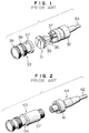
- FIG. 1 illustrates a conventional cable direct fitting type connecting method.
- Designated at 31 in FIG. 1 is an image sensing device module unit having its lead terminals 35 to which terminal members 36 of a camera cable 34 are soldered. Thereafter, the image sensing device module unit is inserted into a body chassis 32 and a sheath chassis 33, and the connecting portion is fastened with a screw 37, whereby they are united. A cable direct fitting type camera head is thus completed.
- a thread 38 is formed in an outer periphery of the sheath chassis 33; and a lens (not illustrated) is thereby mountable thereto.
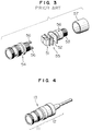
- FIG. 3 is a view fully illustrating a method of assembling the camera head.
- the numeral 51 represents an image sensing device module unit having its lead terminals (not shown) to which a connecting plate 52 made of a flexible material is soldered.
- Indicated at 53 is a connector constituting the other end (opposite to the lens mounting side) of the camera head and having its one end provided with the lead terminals soldered to the connecting plate and the other end provided with a male connector connected to a female connector 41 integrally soldered to the camera cable 42.
- the numeral 54 denotes a sheath chassis into which a unit 55 consisting of the image sensing device, the connecting plate and the male connector is inserted.
- the external appearance of the camera based on the construction of FIG. 1 satisfies the demand of the customer because of the cable direct fitting type. Attaching and detaching the camera cable, however, involve demounting and mounting by hyperfine soldering. This presents such a problem that the operation is not easy, and the customer's demand can not be satisfied. Further, in the construction of FIG. 2, the camera cable is attached and detached by the connector system, which facilitates the operation and meets the customer's demand. In terms of the external appearance of the camera, however, a size of the female connector 41 is substantially equal to that of the camera head 43, which lacks in smartness. A problem is also arises, wherein the demand of the customer can not be satisfied.
- a special female connector unit to which a camera cable is soldered is connected to an image sensing device module having lead terminals and incorporating a pin function of a male connector. Thereafter, a sheath chassis of the image sensing device module is united with a body chassis incorporating a female connector unit by screw-fastening, thus constructing a camera head.
- the female connector unit with the camera cable is connector-fitted to the sheath chassis member incorporating the image sensing device module with pin lead terminals.
- the connector unit is covered with the body chassis, and the body chassis and the sheath chassis are united by screw-fastening. Therefore, the camera head takes the cable direct fitting structure in terms of its external appearance.
- the cable can be demounted and mounted through the connector by loosening the screw fastening portion and removing the screw.
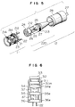
- FIG. 4 is a sketch drawing of a solid state image sensing apparatus in one embodiment of the present invention.
- FIG. 5 illustrates a construction of the solid state image sensing apparatus in the embodiment.
- FIG. 6 depicts a construction of an image sensing module unit in the embodiment.
- the numeral 11 designates an image sensing device module; 12 a connector module; 13 a camera head; and 21 an image sensing device module unit consisting of lead terminals 22 incorporating a pin function of a male connector, an image sensing device chip, a device driving circuit board and a spatial filter.
- the image sensing device module unit 21 is, as illustrated in FIG. 6, composed of an image sensing device chip 311, an optical glass 313, device driving circuit boards 314, 315, 316 each packed with a driving circuit for the image sensing device chip 311, and lead terminals 22. Then, the optical glass 313 is fitted to a light receiving surface of the image sensing device chip 311.
- the device driving circuit boards 314, 315, 316 are held and fixed with connecting pins 317.
- electrodes 314e, 315e, 316e are formed on the side portions of the device driving circuit boards 314, 315, 316. These electrodes are connected to an outer lead 311m connected to a device electrode (unillustrated) of the image sensing device chip 311. Further, metallic lead terminals 22 are attached to the bottom of the device driving circuit board 316.
- the numeral 23 represents a sheath chassis into which the image sensing device module unit 21 is fixedly inserted.
- An image sensing device module 11 is thus completed.
- Designated at 24 is a female connector fixed to a cable clamp 25 with a screw 26.
- a camera cable generally indicated at 27 passes through through-holes of the body chassis 28 and the cable clamp 25 and is thereafter fixed in a predetermined position of the cable clamp 25; and terminals thereof are soldered to cable connecting terminals 29 of the female connector 24.
- a connector unit 220 and a connector module 12 are thus completed.
- lead terminal pins 22 of the image sensing device module are connector-joined to the female connector 24 of the connector module.
- the body chassis and the cable clamp are screw-fastened and united by engaging a thread (unillustrated) formed inwardly of the body chassis 28 with a thread 213 formed in an outer periphery of the cable clamp, thus completing the camera head 13.
- a thread 214 is formed in an outer periphery of the sheath chassis 23, whereby a lens (not shown) is mountable thereto.
- the image sensing device module incorporates the image sensing device module unit in which the image sensing device chip is directly connected to the sheath chassis.
- the image sensing device module is connected to the connector module in which the body chassis incorporates the connector unit, thus completing the camera head.
- the camera head therefore takes a cable direct fitting structure in terms of its external appearance.
- the connector structure in which the cable is attachable and detachable simply by demounting the screw fastening portion of the connecting member.
Abstract
Description
- The present invention relates generally to a cable connecting structure of a solid state image sensing apparatus and, more particularly, to a camera cable connecting structure in a separate type camera composed of a camera head and a camera control unit.
- In recent years, there has been remarkably increasingly a demand for a separate type camera utilizing such a characteristic that a solid state image sensing device is easily reduced both in size and in weight. Under such circumstances, there has arisen a customer's new demand for a camera cable connecting method of connecting a camera head to a camera control unit (hereinafter abbreviated to CCU), especially a connecting mode of the camera head and a camera cable. Namely, a cable direct fitting type is desirable in terms of design as an external appearance of a connecting portion between the camera head and the camera cable. In terms of attaching and detaching the camera cable, however, it is desirable to incorporate a connector function.
- The following is an explanation of a conventional method of connecting the camera head to the camera cable.
- FIG. 1 illustrates a conventional cable direct fitting type connecting method. Designated at 31 in FIG. 1 is an image sensing device module unit having its
lead terminals 35 to whichterminal members 36 of acamera cable 34 are soldered. Thereafter, the image sensing device module unit is inserted into abody chassis 32 and asheath chassis 33, and the connecting portion is fastened with ascrew 37, whereby they are united. A cable direct fitting type camera head is thus completed. Note that athread 38 is formed in an outer periphery of thesheath chassis 33; and a lens (not illustrated) is thereby mountable thereto. - FIG. 2 of another conventional example, showing a connector connecting method. FIG. 3 is a view fully illustrating a method of assembling the camera head. Referring to FIGS. 2 and 3, the
numeral 51 represents an image sensing device module unit having its lead terminals (not shown) to which a connectingplate 52 made of a flexible material is soldered. Indicated at 53 is a connector constituting the other end (opposite to the lens mounting side) of the camera head and having its one end provided with the lead terminals soldered to the connecting plate and the other end provided with a male connector connected to afemale connector 41 integrally soldered to thecamera cable 42. Thenumeral 54 denotes a sheath chassis into which aunit 55 consisting of the image sensing device, the connecting plate and the male connector is inserted. These components are fastened with ascrew 56, and then thebody chassis 57 and thesheath chassis 54 are also fastened with a screw, thus completing thecamera head 43. The customer uses the camera by connecting the male connector of the camera head to thefemale connector 41 of acable assembly 44. - In the conventional example described above, however, the external appearance of the camera based on the construction of FIG. 1 satisfies the demand of the customer because of the cable direct fitting type. Attaching and detaching the camera cable, however, involve demounting and mounting by hyperfine soldering. This presents such a problem that the operation is not easy, and the customer's demand can not be satisfied. Further, in the construction of FIG. 2, the camera cable is attached and detached by the connector system, which facilitates the operation and meets the customer's demand. In terms of the external appearance of the camera, however, a size of the
female connector 41 is substantially equal to that of thecamera head 43, which lacks in smartness. A problem is also arises, wherein the demand of the customer can not be satisfied. - It is an object of the present invention, which obviates the problem given above, to provide a solid state image sensing apparatus wherein a camera head takes a camera cable direct fitting type in its external appearance, and attaching and detaching of the camera cable are facilitated based on a connector structure incorporated into a camera.
- To accomplish the object described above, in the solid state image sensing apparatus of the present invention, a special female connector unit to which a camera cable is soldered is connected to an image sensing device module having lead terminals and incorporating a pin function of a male connector. Thereafter, a sheath chassis of the image sensing device module is united with a body chassis incorporating a female connector unit by screw-fastening, thus constructing a camera head.
- Hence, according to the construction of the present invention, in the camera head, the female connector unit with the camera cable is connector-fitted to the sheath chassis member incorporating the image sensing device module with pin lead terminals. Next, the connector unit is covered with the body chassis, and the body chassis and the sheath chassis are united by screw-fastening. Therefore, the camera head takes the cable direct fitting structure in terms of its external appearance. When attaching and detaching the cable, the cable can be demounted and mounted through the connector by loosening the screw fastening portion and removing the screw.
- Other objects and advantages of the present invention will become apparent during the following discussion taken in conjunction with the reference drawings, in which:
- FIG. 1 is a block diagram illustrating a conventional solid state image sensing apparatus;
- FIG. 2 is a sketch drawing of another conventional solid state image sensing apparatus;
- FIG. 3 is a view fully depicting a construction of the solid state image sensing apparatus of FIG. 2;
- FIG. 4 is a sketch drawing of a solid state image sensing apparatus in one embodiment of the present invention;
- FIG. 5 is a block diagram fully illustrating the solid state image sensing apparatus shown in FIG. 4; and
- FIG. 6 is a block diagram fully illustrating an image sensing device module unit shown in FIG. 5.
- FIG. 4 is a sketch drawing of a solid state image sensing apparatus in one embodiment of the present invention. FIG. 5 illustrates a construction of the solid state image sensing apparatus in the embodiment. FIG. 6 depicts a construction of an image sensing module unit in the embodiment. Referring to FIGS. 4 and 5, the numeral 11 designates an image sensing device module; 12 a connector module; 13 a camera head; and 21 an image sensing device module unit consisting of
lead terminals 22 incorporating a pin function of a male connector, an image sensing device chip, a device driving circuit board and a spatial filter. - Herein, the image sensing
device module unit 21 is, as illustrated in FIG. 6, composed of an imagesensing device chip 311, anoptical glass 313, devicedriving circuit boards sensing device chip 311, andlead terminals 22. Then, theoptical glass 313 is fitted to a light receiving surface of the imagesensing device chip 311. The devicedriving circuit boards pins 317. Besides,electrodes driving circuit boards sensing device chip 311. Further,metallic lead terminals 22 are attached to the bottom of the devicedriving circuit board 316. - Turning next to FIG. 5, the
numeral 23 represents a sheath chassis into which the image sensingdevice module unit 21 is fixedly inserted. An image sensing device module 11 is thus completed. Designated at 24 is a female connector fixed to acable clamp 25 with ascrew 26. A camera cable generally indicated at 27 passes through through-holes of thebody chassis 28 and thecable clamp 25 and is thereafter fixed in a predetermined position of thecable clamp 25; and terminals thereof are soldered tocable connecting terminals 29 of thefemale connector 24. Aconnector unit 220 and aconnector module 12 are thus completed. - Next,
lead terminal pins 22 of the image sensing device module are connector-joined to thefemale connector 24 of the connector module. After they have been made integral by fastening with ascrew 212, the body chassis and the cable clamp are screw-fastened and united by engaging a thread (unillustrated) formed inwardly of thebody chassis 28 with athread 213 formed in an outer periphery of the cable clamp, thus completing thecamera head 13. Note that athread 214 is formed in an outer periphery of thesheath chassis 23, whereby a lens (not shown) is mountable thereto. - As discussed above, in accordance with this embodiment, the image sensing device module incorporates the image sensing device module unit in which the image sensing device chip is directly connected to the sheath chassis. The image sensing device module is connected to the connector module in which the body chassis incorporates the connector unit, thus completing the camera head. The camera head therefore takes a cable direct fitting structure in terms of its external appearance. Provided further is the connector structure in which the cable is attachable and detachable simply by demounting the screw fastening portion of the connecting member. Hence, it is possible to provide the camera head structure which sufficiently satisfies the demand of the customer.
- Although the illustrative embodiment has been described in detail with reference to the accompanying drawings, it is to be understood that the present invention is not limited to this embodiment. Various changes or modification may be effected therein by one skilled in the art without departing from the scope or spirit of the invention.
Claims (2)
- A solid state image sensing apparatus comprising:
a female connector fixed to a cable clamp;
a cable connected to cable connecting terminals of said female connector via through-holes of a body chassis and of said cable clamp;
an image sensing device module in which an electrode of an image sensing device chip is connected through a metallic lead to electrodes disposed on the side surfaces of device driving circuit boards, and lead terminals are disposed on said device driving circuit board; and
a sheath chassis encasing said image sensing device module,
characterized in that a signal of said image sensing device chip is transmitted to said cable by fitting said lead terminals to said female connector. - The solid state image sensing apparatus as set forth in claim 1, wherein said lead terminals are inserted into said female connector, said sheath chassis and said female connector are fastened with a screw, said body chassis and said cable clamp are screw-fastened and united by engaging a thread formed inwardly of said body chassis with a thread formed in an outer periphery of said cable clamp, and said body chassis is united with said sheath chassis.
Applications Claiming Priority (2)
| Application Number | Priority Date | Filing Date | Title |
|---|---|---|---|
| JP3114767A JP2858173B2 (en) | 1991-05-20 | 1991-05-20 | Solid-state imaging device |
| JP114767/91 | 1991-05-20 |
Publications (3)
| Publication Number | Publication Date |
|---|---|
| EP0515085A2 true EP0515085A2 (en) | 1992-11-25 |
| EP0515085A3 EP0515085A3 (en) | 1993-01-13 |
| EP0515085B1 EP0515085B1 (en) | 1996-11-27 |
Family
ID=14646181
Family Applications (1)
| Application Number | Title | Priority Date | Filing Date |
|---|---|---|---|
| EP92304317A Expired - Lifetime EP0515085B1 (en) | 1991-05-20 | 1992-05-13 | Cable connecting structure of a solid state image sensor |
Country Status (4)
| Country | Link |
|---|---|
| US (1) | US5287191A (en) |
| EP (1) | EP0515085B1 (en) |
| JP (1) | JP2858173B2 (en) |
| DE (1) | DE69215433T2 (en) |
Cited By (3)
| Publication number | Priority date | Publication date | Assignee | Title |
|---|---|---|---|---|
| GB2286501A (en) * | 1994-02-10 | 1995-08-16 | Robin Staniforth | Surveillance system and device |
| FR2751197A1 (en) * | 1996-07-18 | 1998-01-23 | Tokendo Sarl | Video endoscope remote probe device for medical and industrial applications |
| EP1265670A2 (en) * | 2000-03-23 | 2002-12-18 | Daniel Eduard Kleiner | A device incorporating a hollow element for being positioned along a body cavity of a patient and method of positioning same |
Families Citing this family (12)
| Publication number | Priority date | Publication date | Assignee | Title |
|---|---|---|---|---|
| TW382180B (en) * | 1996-07-15 | 2000-02-11 | Sony Corp | Camera lens |
| JPH1032739A (en) * | 1996-07-15 | 1998-02-03 | Sony Corp | Flexible printed wiring board system |
| US6246449B1 (en) * | 1996-08-16 | 2001-06-12 | Rosen Products Llc | Display unit |
| US5946055A (en) * | 1996-08-16 | 1999-08-31 | Rosen Product Development, Inc. | Display unit |
| US6095970A (en) * | 1997-02-19 | 2000-08-01 | Asahi Kogaku Kogyo Kabushiki Kaisha | Endoscope |
| US6292236B1 (en) | 1999-03-26 | 2001-09-18 | Rosen Products Llc | Automotive-ceiling-mounted monitor |
| USD446507S1 (en) | 1999-06-18 | 2001-08-14 | Rosen Products Llc | Ceiling-mounted monitor |
| US20060217594A1 (en) * | 2005-03-24 | 2006-09-28 | Ferguson Gary W | Endoscopy device with removable tip |
| US8617059B2 (en) * | 2005-05-27 | 2013-12-31 | Olympus Corporation | Endoscopic apparatus and endoscope adapter |
| US20140188086A1 (en) * | 2012-12-31 | 2014-07-03 | Biosense Webster (Israel), Ltd. | Catheter connector |
| JP7372513B2 (en) * | 2018-12-05 | 2023-11-01 | ミツミ電機株式会社 | Imaging devices, imaging systems, and industrial robots |
| KR102184079B1 (en) * | 2019-02-01 | 2020-11-27 | 주식회사 지아이티 | Industrial camera and diagnostics system |
Citations (5)
| Publication number | Priority date | Publication date | Assignee | Title |
|---|---|---|---|---|
| FR2274181A1 (en) * | 1974-06-10 | 1976-01-02 | Inspectronic | Cylindrical T.V. camera unit - is connected to central sender unit in cylindrical block of same diameter |
| EP0080930A2 (en) * | 1981-11-27 | 1983-06-08 | The Bendix Corporation | Electrical connector assembly |
| US4918521A (en) * | 1987-01-20 | 1990-04-17 | Olympus Optical Co., Ltd. | Solid state imaging apparatus |
| US4974075A (en) * | 1987-08-11 | 1990-11-27 | Olympus Optical Co., Ltd. | Image pickup apparatus having connector capable of separately shielding grouped electrical connections |
| EP0492349A1 (en) * | 1990-12-28 | 1992-07-01 | Matsushita Electric Industrial Co., Ltd. | Camera head for solid-state image pickup device and method of producing same |
Family Cites Families (4)
| Publication number | Priority date | Publication date | Assignee | Title |
|---|---|---|---|---|
| US2890434A (en) * | 1955-10-21 | 1959-06-09 | Anatoly B Ray | Electrical disconnect safety lock |
| US4838805A (en) * | 1984-01-05 | 1989-06-13 | Raytheon Company | Connector engaging nut locking mechanism |
| JPS6159974A (en) * | 1984-08-31 | 1986-03-27 | Canon Inc | Electronic camera and lens barrel |
| JPH0530307Y2 (en) * | 1987-02-12 | 1993-08-03 |
-
1991
- 1991-05-20 JP JP3114767A patent/JP2858173B2/en not_active Expired - Fee Related
-
1992
- 1992-05-08 US US07/879,903 patent/US5287191A/en not_active Expired - Fee Related
- 1992-05-13 DE DE69215433T patent/DE69215433T2/en not_active Expired - Fee Related
- 1992-05-13 EP EP92304317A patent/EP0515085B1/en not_active Expired - Lifetime
Patent Citations (5)
| Publication number | Priority date | Publication date | Assignee | Title |
|---|---|---|---|---|
| FR2274181A1 (en) * | 1974-06-10 | 1976-01-02 | Inspectronic | Cylindrical T.V. camera unit - is connected to central sender unit in cylindrical block of same diameter |
| EP0080930A2 (en) * | 1981-11-27 | 1983-06-08 | The Bendix Corporation | Electrical connector assembly |
| US4918521A (en) * | 1987-01-20 | 1990-04-17 | Olympus Optical Co., Ltd. | Solid state imaging apparatus |
| US4974075A (en) * | 1987-08-11 | 1990-11-27 | Olympus Optical Co., Ltd. | Image pickup apparatus having connector capable of separately shielding grouped electrical connections |
| EP0492349A1 (en) * | 1990-12-28 | 1992-07-01 | Matsushita Electric Industrial Co., Ltd. | Camera head for solid-state image pickup device and method of producing same |
Cited By (5)
| Publication number | Priority date | Publication date | Assignee | Title |
|---|---|---|---|---|
| GB2286501A (en) * | 1994-02-10 | 1995-08-16 | Robin Staniforth | Surveillance system and device |
| GB2286501B (en) * | 1994-02-10 | 1998-04-15 | Robin Staniforth | Surveillance system and device |
| FR2751197A1 (en) * | 1996-07-18 | 1998-01-23 | Tokendo Sarl | Video endoscope remote probe device for medical and industrial applications |
| EP1265670A2 (en) * | 2000-03-23 | 2002-12-18 | Daniel Eduard Kleiner | A device incorporating a hollow element for being positioned along a body cavity of a patient and method of positioning same |
| EP1265670A4 (en) * | 2000-03-23 | 2005-06-01 | Daniel Eduard Kleiner | A device incorporating a hollow element for being positioned along a body cavity of a patient and method of positioning same |
Also Published As
| Publication number | Publication date |
|---|---|
| EP0515085A3 (en) | 1993-01-13 |
| JPH04342383A (en) | 1992-11-27 |
| JP2858173B2 (en) | 1999-02-17 |
| US5287191A (en) | 1994-02-15 |
| EP0515085B1 (en) | 1996-11-27 |
| DE69215433T2 (en) | 1997-03-27 |
| DE69215433D1 (en) | 1997-01-09 |
Similar Documents
| Publication | Publication Date | Title |
|---|---|---|
| EP0515085A2 (en) | Cable connecting structure of a solid state image sensor | |
| US10518724B2 (en) | Method for assembling a vehicular camera | |
| KR100633608B1 (en) | LCD Display | |
| US6977783B2 (en) | Lens module and assembling method thereof | |
| EP0492349B1 (en) | Camera head for solid-state image pickup device and method of producing same | |
| CN110618514A (en) | Optical device for vehicle comprising heating element | |
| US8289720B2 (en) | Electronic apparatus | |
| US20020142633A1 (en) | Shielded cable connector and electronic device | |
| US5521670A (en) | Camera utilizing horizontal and vertical board connectors | |
| JP2606103Y2 (en) | Jack connector device | |
| US20210136356A1 (en) | Vehicular camera testing system using spring-loaded electrical connectors | |
| JPH065765Y2 (en) | Electronic endoscope | |
| JP2902654B2 (en) | Electrical connector | |
| CN219145476U (en) | Lens module and vehicle | |
| JP4250480B2 (en) | Solid-state imaging device | |
| US20220158383A1 (en) | Connector | |
| JPS62163473A (en) | Fitting device for solid-state image pickup element of video camera | |
| JPS6219812A (en) | Active connector incorporating optical transmission module | |
| JP3768573B2 (en) | Imaging device | |
| JPH0418260Y2 (en) | ||
| JP2023106172A (en) | Imaging device | |
| JPH05207341A (en) | Optical block attaching and detaching device for camera | |
| JP2000082514A (en) | Connecting structure for electric wiring board | |
| JPH0682891A (en) | Electric circuit connecting structure for camera | |
| JPH05335603A (en) | Package for optical transmission-reception module |
Legal Events
| Date | Code | Title | Description |
|---|---|---|---|
| PUAI | Public reference made under article 153(3) epc to a published international application that has entered the european phase |
Free format text: ORIGINAL CODE: 0009012 |
|
| PUAL | Search report despatched |
Free format text: ORIGINAL CODE: 0009013 |
|
| AK | Designated contracting states |
Kind code of ref document: A2 Designated state(s): DE FR GB |
|
| AK | Designated contracting states |
Kind code of ref document: A3 Designated state(s): DE FR GB |
|
| 17P | Request for examination filed |
Effective date: 19930219 |
|
| 17Q | First examination report despatched |
Effective date: 19941011 |
|
| GRAG | Despatch of communication of intention to grant |
Free format text: ORIGINAL CODE: EPIDOS AGRA |
|
| GRAH | Despatch of communication of intention to grant a patent |
Free format text: ORIGINAL CODE: EPIDOS IGRA |
|
| GRAH | Despatch of communication of intention to grant a patent |
Free format text: ORIGINAL CODE: EPIDOS IGRA |
|
| GRAA | (expected) grant |
Free format text: ORIGINAL CODE: 0009210 |
|
| AK | Designated contracting states |
Kind code of ref document: B1 Designated state(s): DE FR GB |
|
| REF | Corresponds to: |
Ref document number: 69215433 Country of ref document: DE Date of ref document: 19970109 |
|
| ET | Fr: translation filed | ||
| PLBE | No opposition filed within time limit |
Free format text: ORIGINAL CODE: 0009261 |
|
| STAA | Information on the status of an ep patent application or granted ep patent |
Free format text: STATUS: NO OPPOSITION FILED WITHIN TIME LIMIT |
|
| 26N | No opposition filed | ||
| REG | Reference to a national code |
Ref country code: GB Ref legal event code: IF02 |
|
| PGFP | Annual fee paid to national office [announced via postgrant information from national office to epo] |
Ref country code: DE Payment date: 20050506 Year of fee payment: 14 |
|
| PGFP | Annual fee paid to national office [announced via postgrant information from national office to epo] |
Ref country code: GB Payment date: 20050511 Year of fee payment: 14 Ref country code: FR Payment date: 20050511 Year of fee payment: 14 |
|
| PG25 | Lapsed in a contracting state [announced via postgrant information from national office to epo] |
Ref country code: GB Free format text: LAPSE BECAUSE OF NON-PAYMENT OF DUE FEES Effective date: 20060513 |
|
| PG25 | Lapsed in a contracting state [announced via postgrant information from national office to epo] |
Ref country code: DE Free format text: LAPSE BECAUSE OF NON-PAYMENT OF DUE FEES Effective date: 20061201 |
|
| GBPC | Gb: european patent ceased through non-payment of renewal fee |
Effective date: 20060513 |
|
| REG | Reference to a national code |
Ref country code: FR Ref legal event code: ST Effective date: 20070131 |
|
| PG25 | Lapsed in a contracting state [announced via postgrant information from national office to epo] |
Ref country code: FR Free format text: LAPSE BECAUSE OF NON-PAYMENT OF DUE FEES Effective date: 20060531 |